EP3141641A1 - Dispositif pour réensoupler une nappe de fils et dispositif d'ourdissage - Google Patents
Dispositif pour réensoupler une nappe de fils et dispositif d'ourdissage Download PDFInfo
- Publication number
- EP3141641A1 EP3141641A1 EP15184265.5A EP15184265A EP3141641A1 EP 3141641 A1 EP3141641 A1 EP 3141641A1 EP 15184265 A EP15184265 A EP 15184265A EP 3141641 A1 EP3141641 A1 EP 3141641A1
- Authority
- EP
- European Patent Office
- Prior art keywords
- thread
- umbäumanordnung
- arrangement
- clip
- thread clip
- Prior art date
- Legal status (The legal status is an assumption and is not a legal conclusion. Google has not performed a legal analysis and makes no representation as to the accuracy of the status listed.)
- Withdrawn
Links
Images


Classifications
-
- D—TEXTILES; PAPER
- D02—YARNS; MECHANICAL FINISHING OF YARNS OR ROPES; WARPING OR BEAMING
- D02H—WARPING, BEAMING OR LEASING
- D02H7/00—Combined warping and beaming machines
-
- D—TEXTILES; PAPER
- D02—YARNS; MECHANICAL FINISHING OF YARNS OR ROPES; WARPING OR BEAMING
- D02H—WARPING, BEAMING OR LEASING
- D02H5/00—Beaming machines
-
- D—TEXTILES; PAPER
- D02—YARNS; MECHANICAL FINISHING OF YARNS OR ROPES; WARPING OR BEAMING
- D02H—WARPING, BEAMING OR LEASING
- D02H3/00—Warping machines
Definitions
- the invention relates to a Umbäuman extract a warping device with a Bäuman Aunt, a Schran extract and at least one thread clip.
- the warping device can be designed as a cone warping machine, on whose example the invention will be explained below.
- the cone warping machine is used to produce a weave tree.
- a chain is sharpened on a warping drum of the cone warping machine. This process takes place in the Schwarzranowski the Schwarztechnisch.
- the generated chain must be transferred from the shear arrangement to the tree arrangement.
- the chain (thread group) is set in the thread clip.
- the thread clip can have a high weight.
- the weight of the thread clip depends on the one hand on the material from which these is formed. On the other hand, their weight also depends on the number of threads specified in it.
- the invention is therefore based on the object to enable the Umbäumvorgang at a warping in a simple manner.
- the object of the invention is achieved in that the Umbäuman extract has a transport arrangement by means of which the thread cleat is positionable in different positions between the tree arrangement and the Schaeran nie.
- the transport arrangement is used for automated displacement of the thread clip between the tree arrangement and the Schaeranssen.
- the transport arrangement thus assumes for the operator of the warping device the transport of the thread cleat from the shear arrangement to the tree arrangement.
- the operator of the warping now done only the hanging of the thread clip on the transport assembly and the later unhooking of the thread clip.
- the hanging and unhooking the thread clip can be done at easily accessible locations of the warping device.
- the limited available at the warping device for handling the thread clip by the operator Space is therefore no longer a problem.
- the operator does not have to manually transport the thread cleat from the shearing assembly to the tree arrangement.
- the handling of the sometimes heavy thread clip is made easier for the operator.
- the error rate of the rebuilding process is minimized.
- the Umbäumanowski allows easy rebuilding.
- the thread cleat is positionable in a first position in a direction of gravity above the Schaeran Mr.
- the thread clip is positioned completely outside the action range of the Schaeran Mr.
- the positioning of the thread clip above the hinge arrangement takes place after completion of the warping process.
- the operator can then fix the yarn sheet of the chain to a clamp rod.
- the clamping bar is fixed in the thread clip.
- the thread clip is hung in the transport arrangement. Further handling of the thread clip by the operator is thereafter no longer necessary.
- the thread cleat is positionable in a second position in the direction of gravity above the tree arrangement.
- the suture clip is positioned above the tree arrangement so that it is completely out of the scope of the tree arrangement. In this position, it can not adversely affect the function of the tree arrangement.
- the tree arrangement typically includes a scaffold with a safety curtain over a tree.
- the transport arrangement can be installed on the frame of the tree arrangement.
- the Umbäumvorgang by Umbäumanowski can now proceed as follows. At the beginning of the warping operation in the shearing arrangement, the thread cleat will be positioned in the second position above the tree arrangement. In this second position, the thread cleat can not adversely affect the warping process in the Schaeran Aunt.
- the operator can position the thread clip by means of the transport arrangement in the first position above the hinge arrangement. This process can be completely automated. A manual handling of the thread clip by the operator is not required. The operator can then fix the yarn sheet of the chain on the clamp rod and set in the thread clip. The thread clip is already hooked in this process in the transport arrangement. The hanging of the thread clip in the transport arrangement can be done either in the second position above the Bäumanowski or in the first position above the Schran eleven. After the yarn sheet of the chain has been set in the thread clip, the operator can position the thread clip above the tree arrangement. This positioning can also be completely automated. A handling of the thread clip by the operator between the Schaeranowski and the tree arrangement is not necessary. The operator can remove the yarn sheet of the chain above the tree again from the thread clip. The Umbäumvorgang can thus run in a simple manner almost completely automated.
- the transport arrangement has at least one restoring element, by which the thread cleat is movable in a linear movement from the second position to the first position.
- the return element of the transport arrangement allows the automated movement of the thread cleat from the second position to the first position.
- the thread clip is thereby moved in a linear movement between the second position and the first position.
- the linear movement of the thread cleat between the second position and the first position enables the simplest possible transport of the thread cleat.
- the thread cleat can be moved above and at the same time within the range of the Schwarzran eleven and the tree arrangement. It is not necessary for the suture clip to leave the area of the sash assembly and tree arrangement during the transplanting operation. Furthermore, a bulky pivoting of the thread clip is avoided for example on a circular path.
- the restoring element has at least one spring element, wherein the thread cleat is movable by an interaction of the restoring element with the spring element in the first position.
- the spring element is a structurally simple way to move the thread clip in the first position above the Schaeranssen.
- the spring element can be arranged, for example under a bias on the return element. This bias results in a force on the return element that moves the thread cleat to the first position.
- the thread clip can be fixed in the first position by the cooperation of the restoring element with the spring element.
- the bias of the spring element moves the thread clip in the first position and holds them in this. It is ensured that the thread cleat is reliably positioned in the first position above the Schaeran Mr. A possible clumsy handling of the thread cleat above the Schaeran Mr by the operator thus does not directly result in that the thread cleat is displaced again from the first position above the Schaeranowski. For this would have the Operator first apply the force to the restoring element, with which this is acted upon by the bias of the spring element.
- the transport arrangement has at least one drive element, by means of which the thread cleat is movable in a linear movement from the first position to the second position.
- the implementation of the movement of the thread cleat from the second position to the first position thus differs from the movement of the thread cleat from the first position to the second position.
- the movement of the thread clip from the second position to the first position is done by the return element.
- This movement is made possible by the spring element.
- the spring element acts under a certain force on the return element. Upon movement of the thread clip from the first position to the second position, this force must be overcome.
- the transport arrangement on the drive element. During a movement of the thread clip from the first position to the second position, the drive element thus overcomes the forces that act on the return element. The overcoming of these forces can be automated. A manual intervention of the operator in this process is not necessary.
- the return element is connected to the thread clip and a base on which the drive element is arranged.
- the thread clip can be switched on and off at the transport arrangement. Once the thread clip is hung on the transport assembly, it is connected to the return element. As a result, the movement of the thread clip is made possible from the second position to the first position.
- the base of the transport arrangement is preferably arranged in the direction of gravity above the tree arrangement. The position of the base can then match the second position. The base is fixed in place with respect to the tree arrangement.
- the thread clip can be moved from the base by means of the return element in the first position above the Schaan Mr.
- the base serves to accommodate the drive element. This is located at the base. As a result, a compact design of the Umbäumanowski is possible. This can be arranged to save space in the warping device.
- the drive member is formed as a roller having a band or a rope attached to the thread cleat.
- the role is arranged at the base.
- the tape or rope is unrolled from the roll.
- the tape or rope is stretched.
- the movement of the thread clip from the first position to the second position is then done simply by rolling the tape or rope on the roll.
- the thread cleat is moved against the force exerted by the spring element on the return element force in the second position.
- the return element is designed as an articulated arm and the spring element as a spring, wherein the spring cooperates with a joint of the articulated arm.
- the bias of the spring then moves the articulated arm to its "extended" position. In this extended position, the return element is arranged such that the thread cleat is fixed in the first position.
- an articulated arm allows the linear movement of the thread clip from the second position to the first position.
- the return element may be formed as a telescopic arm.
- the invention relates to a warping device with the Umbäumanowski invention and with a Bäuman extract, a Schran extract and at least one thread clip.
- the invention is based, to allow the Umbäumvorgang at a warping in a simple way the task.
- the operator of the warping device can control the transport arrangement of the Umbäuman Ich invention in a simple manner by means of the control element.
- the operating element is arranged on the tree arrangement or the Schaeran Ich and thus easily accessible to the operator. A work of the operator in the difficult to reach space between the Schaeran Ich and the tree arrangement can be avoided.
- the operator can activate the transport arrangement, for example, by simply pressing a button on the operating element. This allows him to initiate the Umbäumvorgang. An automated operation of the Umbäumanowski is possible. The manual operation by the operator can be largely avoided.
- the tree arrangement has at least one tree, wherein the base is arranged on a side facing away from the Scharan eleven the tree. On a side facing away from the Scharanowski the tree is typically a scaffold with a security process attached. The base can also be fixed to the scaffolding. The takeover order is then completely outside the scope of the tree arrangement appropriate. An adverse effect of the Umbäumanowski on the Bäumvorgang can be avoided. It is also possible to position the thread clip in any position above the tree.
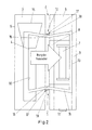
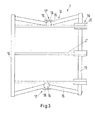
- the Fig. 1 to 4 show a Umbäuman extract 1 a warping device. 2
- the warping device 2 has therein a Schran Ich 3.
- the Schranowskiowski Mr 3 comprises a warping drum 4 and a warping cone 5.
- the warping device 2 includes a Bäuman whatsoever 6.
- the Bäuman onion 6 has a tree 7, a roller system 8 and a framework 9 with a safety curtain (not shown).
- the Umbäuman instrument 1 has therein a thread group 10, an operating element 11 (see Fig. 1 and 2 ) and a transport arrangement 12.
- the transport arrangement 12 in turn comprises a base 13 and a return element 14.
- the return element 14 is exemplified as an articulated arm 15 with a hinge 16.
- the restoring element has a spring element 17, which in the present case is designed as a spring 18.
- the drive element 19 is exemplified as a roller 20 to which a belt 21 is attached.
- Fig. 1 shows the Umbäumanowski 11 of the warping device 2 in a starting position.
- the base 13 of the Umbäumanowski 11 is installed on the frame 9 of the tree arrangement 6.
- the base 13 is arranged on a side facing away from the Schwarzran whatsoever 3 of the tree 7.
- the thread clip 10 connected to the return element 14 is in this initial position in a second position.
- the second position is located in a direction of gravity above the beam arrangement 6.
- the Umbäumanowskiowski 1 does not overlap with the Schnran whatsoever 3.
- the Umbäumanowski 11 is disposed completely outside the scope of the Schranowskiowski 3.
- the warping process can be done trouble-free.
- an operator of the warping device 2 will control the transport arrangement 12, for example by pressing a button on the operating element 11.
- the thread clip 10 is moved from the second position above the beam arrangement 6 into a first position above the hinge arrangement 3.
- the movement of the thread loop 10 from the second position to the first position is linear.
- the movement of the thread loop 10 is made possible in the embodiment shown by the return element 14 and the spring element 17.
- the spring element 17 In the starting position of the Umbäuman note 1, the spring element 17 has a certain bias. This bias acts on the return element 14 with a force. This force causes the thread clip 10 to be moved to the first position.
- the band 21 is tensioned while being unrolled from the roller 20.
- the band 21 is fastened to the thread clip 10.
- the roller 20 is connected to the base 13. Due to the interaction of the return element 14 and the spring element 17, the thread clip 10 is fixed in the first position.
- the thread clip 10 In the end position now reached, the thread clip 10 is located in the direction of gravity above the hinge arrangement 3. It is now possible for the operator to fix the thread share of the chain on a clamping rod (not shown) and fix it in the thread clip 10. Once this process is completed, the operator goes back to the control element 11 and presses it again. By re-operation, the thread clip 10 is now moved from the first position to the second position. This movement of the thread loop 10 from the first position to the second position is linear.
- the movement of the thread loop 10 from the first position to the second position is implemented by the following technical features.
- the belt 21 is wound by a rotational movement of the roller 20 on this.
- the band 21 is connected to the thread clip 10.
- the force exerted by the spring element 17 on the return element 14 must be overcome.
- the thread clip 10 is returned to the starting position.
- the operator can the yarn sheet of the chain over the tree 7 again remove the thread clip 10.
- the yarn sheet of the chain can now be easily brought into engagement with the tree 7.
Landscapes
- Engineering & Computer Science (AREA)
- Textile Engineering (AREA)
- Warping, Beaming, Or Leasing (AREA)
Priority Applications (2)
| Application Number | Priority Date | Filing Date | Title |
|---|---|---|---|
| EP15184265.5A EP3141641A1 (fr) | 2015-09-08 | 2015-09-08 | Dispositif pour réensoupler une nappe de fils et dispositif d'ourdissage |
| CN201610000722.6A CN106498590B (zh) | 2015-09-08 | 2016-01-04 | 整经设备的倒轴装置和整经设备 |
Applications Claiming Priority (1)
| Application Number | Priority Date | Filing Date | Title |
|---|---|---|---|
| EP15184265.5A EP3141641A1 (fr) | 2015-09-08 | 2015-09-08 | Dispositif pour réensoupler une nappe de fils et dispositif d'ourdissage |
Publications (1)
| Publication Number | Publication Date |
|---|---|
| EP3141641A1 true EP3141641A1 (fr) | 2017-03-15 |
Family
ID=54105650
Family Applications (1)
| Application Number | Title | Priority Date | Filing Date |
|---|---|---|---|
| EP15184265.5A Withdrawn EP3141641A1 (fr) | 2015-09-08 | 2015-09-08 | Dispositif pour réensoupler une nappe de fils et dispositif d'ourdissage |
Country Status (2)
| Country | Link |
|---|---|
| EP (1) | EP3141641A1 (fr) |
| CN (1) | CN106498590B (fr) |
Cited By (1)
| Publication number | Priority date | Publication date | Assignee | Title |
|---|---|---|---|---|
| CN109402820A (zh) * | 2018-12-17 | 2019-03-01 | 广东溢达纺织有限公司 | 整经辅助设备及整经系统 |
Citations (4)
| Publication number | Priority date | Publication date | Assignee | Title |
|---|---|---|---|---|
| DE3340049A1 (de) * | 1983-11-05 | 1985-05-23 | W. Schlafhorst & Co, 4050 Mönchengladbach | Schaer- und baeummaschine |
| DD267274A1 (de) * | 1987-12-24 | 1989-04-26 | Textima Veb K | Einrichtung zur uebergabe von fadenscharen an schaermaschinen |
| EP0391129A2 (fr) * | 1989-04-01 | 1990-10-10 | Hacoba Textilmaschinen GmbH & Co KG | Dispositif pour réensoupler des chaînes ourdies |
| EP0965668A2 (fr) * | 1998-06-17 | 1999-12-22 | Benninger AG | Procédé et dispositif pour transférer une nappe enroulée de fils sur une ensouple |
Family Cites Families (2)
| Publication number | Priority date | Publication date | Assignee | Title |
|---|---|---|---|---|
| CN100582336C (zh) * | 2007-04-30 | 2010-01-20 | 施迎尔 | 高速分条整经机倒轴门幅自动调节系统 |
| CN201377020Y (zh) * | 2009-01-23 | 2010-01-06 | 江阴市通源纺机有限公司 | 小样整经机 |
-
2015
- 2015-09-08 EP EP15184265.5A patent/EP3141641A1/fr not_active Withdrawn
-
2016
- 2016-01-04 CN CN201610000722.6A patent/CN106498590B/zh active Active
Patent Citations (4)
| Publication number | Priority date | Publication date | Assignee | Title |
|---|---|---|---|---|
| DE3340049A1 (de) * | 1983-11-05 | 1985-05-23 | W. Schlafhorst & Co, 4050 Mönchengladbach | Schaer- und baeummaschine |
| DD267274A1 (de) * | 1987-12-24 | 1989-04-26 | Textima Veb K | Einrichtung zur uebergabe von fadenscharen an schaermaschinen |
| EP0391129A2 (fr) * | 1989-04-01 | 1990-10-10 | Hacoba Textilmaschinen GmbH & Co KG | Dispositif pour réensoupler des chaînes ourdies |
| EP0965668A2 (fr) * | 1998-06-17 | 1999-12-22 | Benninger AG | Procédé et dispositif pour transférer une nappe enroulée de fils sur une ensouple |
Cited By (2)
| Publication number | Priority date | Publication date | Assignee | Title |
|---|---|---|---|---|
| CN109402820A (zh) * | 2018-12-17 | 2019-03-01 | 广东溢达纺织有限公司 | 整经辅助设备及整经系统 |
| CN109402820B (zh) * | 2018-12-17 | 2023-10-13 | 广东溢达纺织有限公司 | 整经辅助设备及整经系统 |
Also Published As
| Publication number | Publication date |
|---|---|
| CN106498590A (zh) | 2017-03-15 |
| CN106498590B (zh) | 2019-04-02 |
Similar Documents
| Publication | Publication Date | Title |
|---|---|---|
| DE3028538A1 (de) | Scherenanlage zum schopfen der enden und/oder zum abtrennen von probenstuecken an auf bunde gewickeltem walzband o.dgl. | |
| DE1578655B2 (de) | Einrichtung zum Bespannen von Tennisschlägern | |
| EP3141641A1 (fr) | Dispositif pour réensoupler une nappe de fils et dispositif d'ourdissage | |
| DE2628788C2 (de) | Verfahren und Maschine zum lagerichtigen Einspannen eines mit Seitenscheiben versehenen Wickeltragbaumes | |
| DE2327160A1 (de) | Strangtraeger fuer die kopfabwicklung eines fadenstrangs | |
| DE202015009381U1 (de) | Umbäumanordnung einer Schärvorrichtung und Schärvorrichtung | |
| DE2757679C2 (de) | Fadenkreuzvorrichtung für Schärmaschinen | |
| EP2253753A2 (fr) | Procédé pour coudre un produit de couture | |
| DE3005667C2 (fr) | ||
| DE202019102454U1 (de) | Werkstückbegrenzungsvorrichtung für Elektrowerkzeuge | |
| EP2942217B1 (fr) | Store de fenêtre | |
| EP3511460B1 (fr) | Métier à tricoter à chaîne et procédé d'assistance à l'utilisateur pour métier à tricoter à chaîne | |
| DE967746C (de) | Garnspeichergeraet fuer Schaermaschinen, insbesondere fuer die Kettenwirkerei | |
| DE102019132438A1 (de) | Vorrichtung zum automatischen Nachwellen von Stoffbahnen auf einer Großstickmaschine | |
| CH683193A5 (de) | Vorrichtung zur Ueberwachung des Fadenlaufs an einem Spulengatter. | |
| DE102020133137B4 (de) | Wickelmaschine zum Abwickeln von band- oder streifenförmigem Material sowie zugehöriger Tänzerarm | |
| DE102005005650B4 (de) | Klemmhalterung für den Anfang einer Materialbahn an Ballenumwickelvorrichtungen | |
| EP1813766B1 (fr) | Dispositif de montage d'installations d'ombrage | |
| EP3101162B1 (fr) | Ourdissoir | |
| CH405854A (de) | Vorrichtung zum Spannen eines der Drehmomentübertragung dienenden Riemens | |
| DE9110404U1 (de) | Tellerbremse für Textilfäden | |
| DE254896C (fr) | ||
| DE1560411C3 (de) | Spulvorrichtung für Automatenwebmaschinen | |
| DE2621571C3 (de) | Bewegungsvorrichtung für den Schlitzverschluß einer fotografischen Kamera | |
| DE1209272B (de) | Vorrichtung am Blockwagen einer ortsfesten Saege zum UEbernehmen und zum Ausrichten eines einzuschneidenden Stammes |
Legal Events
| Date | Code | Title | Description |
|---|---|---|---|
| PUAI | Public reference made under article 153(3) epc to a published international application that has entered the european phase |
Free format text: ORIGINAL CODE: 0009012 |
|
| AK | Designated contracting states |
Kind code of ref document: A1 Designated state(s): AL AT BE BG CH CY CZ DE DK EE ES FI FR GB GR HR HU IE IS IT LI LT LU LV MC MK MT NL NO PL PT RO RS SE SI SK SM TR |
|
| AX | Request for extension of the european patent |
Extension state: BA ME |
|
| STAA | Information on the status of an ep patent application or granted ep patent |
Free format text: STATUS: THE APPLICATION IS DEEMED TO BE WITHDRAWN |
|
| 18D | Application deemed to be withdrawn |
Effective date: 20170916 |