EP3141666B1 - Robinetterie, en particulier pour caravane, camping-car ou bateau - Google Patents
Robinetterie, en particulier pour caravane, camping-car ou bateau Download PDFInfo
- Publication number
- EP3141666B1 EP3141666B1 EP16183963.4A EP16183963A EP3141666B1 EP 3141666 B1 EP3141666 B1 EP 3141666B1 EP 16183963 A EP16183963 A EP 16183963A EP 3141666 B1 EP3141666 B1 EP 3141666B1
- Authority
- EP
- European Patent Office
- Prior art keywords
- water
- fitting
- fitting body
- outlet pipe
- water outlet
- Prior art date
- Legal status (The legal status is an assumption and is not a legal conclusion. Google has not performed a legal analysis and makes no representation as to the accuracy of the status listed.)
- Active
Links
Images

Classifications
-
- E—FIXED CONSTRUCTIONS
- E03—WATER SUPPLY; SEWERAGE
- E03C—DOMESTIC PLUMBING INSTALLATIONS FOR FRESH WATER OR WASTE WATER; SINKS
- E03C1/00—Domestic plumbing installations for fresh water or waste water; Sinks
- E03C1/02—Plumbing installations for fresh water
- E03C1/04—Water-basin installations specially adapted to wash-basins or baths
- E03C1/0404—Constructional or functional features of the spout
-
- E—FIXED CONSTRUCTIONS
- E03—WATER SUPPLY; SEWERAGE
- E03C—DOMESTIC PLUMBING INSTALLATIONS FOR FRESH WATER OR WASTE WATER; SINKS
- E03C1/00—Domestic plumbing installations for fresh water or waste water; Sinks
- E03C1/02—Plumbing installations for fresh water
- E03C1/04—Water-basin installations specially adapted to wash-basins or baths
- E03C2001/0414—Water-basin installations specially adapted to wash-basins or baths allowing different orientations of the spout or the outlet nozzle
-
- E—FIXED CONSTRUCTIONS
- E03—WATER SUPPLY; SEWERAGE
- E03C—DOMESTIC PLUMBING INSTALLATIONS FOR FRESH WATER OR WASTE WATER; SINKS
- E03C1/00—Domestic plumbing installations for fresh water or waste water; Sinks
- E03C1/02—Plumbing installations for fresh water
- E03C1/04—Water-basin installations specially adapted to wash-basins or baths
- E03C2001/0417—Water-basin installations specially adapted to wash-basins or baths having space-saving features, e.g. retractable, demountable
Definitions
- the invention relates to a water fitting, in particular for a caravan, caravan, Motorcaravan or a boat, according to the preamble of claim 1.
- Such water fittings especially for caravans, caravans, motor caravans or boats are already well known from the general state of the art.
- a water fitting comprises a fitting body and at least one water outlet pipe, which is held at least indirectly on the fitting body and is pivotable about at least one pivot axis relative to the fitting body.
- the fittings body is for example traversed by water, the water is supplied to the water outlet pipe. Accordingly, the water outlet pipe is also traversed by the water and serves to guide the water to a water outlet, through which the water flows out of the water fitting.
- the space in a caravan, caravan, motor caravan or a boat are very cramped, so that the available space should be used effectively and efficiently.
- an advantageous functionality of the water valve should be maintained.
- the US D464 711 S discloses a water faucet.
- Object of the present invention is therefore to develop a water faucet of the type mentioned in such a way that the space requirement of the water faucet can be kept particularly low while achieving an advantageous function of the water faucet.
- the invention relates to a water fitting, in particular for a caravan, caravan, Motorcaravan or a boat.
- the water fitting has a fitting body and at least one water outlet pipe, which is held at least indirectly on the fitting body and is pivotable about at least one pivot axis relative to the fitting body. This means that the water outlet pipe is pivotally supported on the fitting body, so that the water outlet pipe can be pivoted about the pivot axis relative to the fitting body, while the water outlet pipe is held on the fitting body and connected to the fitting body.
- the water outlet pipe has at least a length range through which a receiving area of the water outlet pipe is limited. Furthermore, the water outlet pipe is pivotable relative to the fitting body between at least one stowed position and at least one use position. In the stowed position, at least one subregion of the fitting body is arranged in the receiving region, wherein the subregion is arranged outside the receiving region in the position of use. With others Words is the portion of the fitting body in the use position of the water outlet pipe is no longer arranged in the receiving area.
- the water fitting according to the invention has - when the water outlet pipe is in the stowed position - a particularly compact design, so that the space requirement of the water fitting can be kept particularly low.
- a sufficiently large height of the water fitting can be realized due to the length range limiting the receiving area, so that, for example, a water spout over which water can flow out of the water fitting is located in a particularly advantageous, high altitude.
- even large objects such as large pots under the located in the use position water outlet pipe and thus placed under the water outlet and filled with water, which flows out of the water outlet pipe.
- the water outlet pipe in the longitudinal region has a recess, which is set back relative to at least one further length region of the water outlet pipe adjoining the length region, wherein at least the partial region of the fitting body is arranged in the stowed position in the recess.
- the length region is curved or bent, so that the length region in the stowage position wraps around at least the portion of the fitting body in its circumferential direction.
- the length region in the stowage position so to speak, surrounds the partial area of the fitting body and wraps around this partial area on the outer circumference, so that the space requirement of the water fitting in the stowage position can be kept particularly low while realizing a particularly high height of the water outlet pipe or the water outlet in the position of use.
- the pivot axis about which the water outlet pipe relative to the valve body between the stowed position and the use position pivoted is completely outside the fitting body runs.
- the pivot axis does not intersect the fitting body or that no points of intersection of the pivot axis with the fitting body exist.
- a further embodiment is characterized in that a held on the fitting body and of the fitting body, in particular laterally projecting arm is provided, on which the water outlet pipe is held and pivotable about the pivot axis relative to the boom and relative to the fitting body.
- the boom is pivotable about a second pivot axis relative to the fitting body.
- the water outlet pipe in the use position and the boom is pivoted about the second pivot axis relative to the fitting body, the water outlet pipe is mitverschwenkt with the boom relative to the fitting body.
- the height of the water outlet can be adjusted as needed.
- the fitting body through-flowing water via the boom to the water outlet pipe can be fed.
- the water outlet pipe for example via the boom fluidly with the Fitted body, so that the space requirement of the water faucet can be kept very low.
- the water fitting a mounting surface over which the water fitting to a corresponding component of the caravan, caravan, motor caravan or Boots, is supportable, and at least one arranged on a first side of the mounting surface fastening means for at least indirectly attaching the water fitting to the device.
- the fitting body has on a first side opposite the second side of the mounting surface in the stowed position extending in the longitudinal direction of the fitting body height of a maximum of 50 millimeters, in particular a maximum of 40 millimeters.
- Fig. 1 shows in a schematic plan view of a generally designated 10 water fitting, in particular for a caravan, caravan, Motorcaravan or a boat.
- the water fitting 10 comprises a fitting body designated as a whole by 12, which has at least one, in particular two channels through which water can flow and which are not recognizable in the figures.
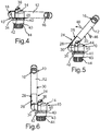
- the water fitting 10 further comprises at least one water outlet pipe 12, which - as particularly good 4 to 6 is recognizable - has a water outlet 16 of the water fitting 10.
- the water outlet pipe 12 is held on the fitting body 14 and thereby pivotable about a first pivot axis 18 relative to the fitting body 14.
- the water outlet pipe 12 has at least one not visible in the figures and can be traversed by water channel, which is fluidly connected to the at least one channel of the fitting body 14 or connectable.
- the channel of the water outlet pipe 12 the water from the at least one channel of the fitting body 14 can be supplied, wherein the channel of the water outlet pipe 12 flowing through the water flow through the water outlet 16 and thus can flow out of the water fitting 10 via the water outlet 16.
- Fig. 1 is a section of a designated 20 component of the caravan, caravan, motor caravan or boat recognizable.
- This component 20 is, for example, a worktop or a sink with a basin 22, into which the water flowing out of the water fitting 10 via the water outlet 16 can flow in and be collected.
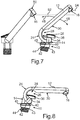
- Fig. 1 to 3 In order to keep the space requirement of the water fitting 10 is particularly low and to realize an advantageous function or functionality of the water faucet, has - as particularly good Fig. 1 to 3 it can be seen - the water outlet pipe 2 at least a length range 24, through which a receiving area 26 is limited. Furthermore, the water outlet pipe 12 between an in Fig. 1 and 4 shown stowage and at least one in Fig. 3 . 6 . 7 and 8 shown use position about the pivot axis 18 relative to the fitting body 14 pivotally. In the stowage position, at least a portion of the fitting body 14 is arranged in the receiving area 26. In the position of use, however, the portion of the fitting body 14 outside of the receiving area 26 is thus not arranged in the receiving area 26.
- the length region is curved or arc-shaped, so that the length region in the stowed position wraps around at least the subregion of the fitting body 14.
- the length region 24 in the stowed position lies around the partial area of the fitting body 14 on the outer circumference, so that the space requirement, in particular the height of the water fitting 10 extending in the longitudinal direction of the fitting body 14, can be kept particularly low.
- the water outlet pipe 12 has a recess 28 in the longitudinal region 24, which is set back relative to at least one further length region 30 of the water outlet pipe 12 adjoining the longitudinal region 24.
- at least the subregion of the fitting body 14 is received in the stowage position in the recess 28, so that the space requirement of the water fitting 10 can be kept very low.
- first pivot axis 18 extends completely outside the fitting body 14. This means that the pivot axis 18 does not intersect the fitting body 14.
- second pivot axis 32 is provided to which that at least indirectly held on the fitting body 14 water outlet pipe 12 is pivotable relative to the fitting body 14. This means that the water outlet pipe 12 can be pivoted about the pivot axes 18 and 32 relative to the fitting body 14, while the water outlet pipe 12 is held on the fitting body 14 and connected thereto.
- the water outlet pipe 12 can first be pivoted around the pivot axis 18 into the use position or into one of a plurality of use positions. Subsequently, the water outlet pipe 12 can be pivoted about the perpendicular to the first pivot axis 18, second pivot axis 32 relative to the fitting body 14 so that, for example, the position or the height of the water outlet 16 can be adjusted as needed by a person.
- a held on the fitting body 14 and laterally of the fitting body along the pivot axis 32 projecting arm 34 is provided, on which the water outlet pipe 12 is pivotally supported about the pivot axis 18.
- the water outlet pipe 12 is held on the fitting body 14, wherein the arm 34 is pivotable about the second pivot axis 32 relative to the fitting body 14.
- the water outlet pipe 12 is mitverschwenkbar with the boom 34.
- the boom 34 is pivoted about the second pivot axis 32 relative to the fitting body 14, while the water outlet pipe 12 is mitverschwenkt.
- the water outlet pipe 12 is pivotable about the first pivot axis 18 relative to the boom 34.
- the water flowing through the fitting body 14 via the arm 34 to the water outlet pipe 12 can be fed.
- the boom 34th at least one channel through which water can flow, which is fluidically connected on the one hand to the at least one channel of the fitting body 14 and on the other hand to the channel of the water outlet pipe 12.
- a sufficient distance or an advantageous position of the water outlet pipe 12 with respect to the fitting body 14 can be realized, so that the length region 24 can wrap around the fitting body 14 particularly well in the stowage position.
- the water fitting 10 further comprises an operating element in the form of an operating lever 36, which is held movably on the fitting body 14.
- the operating lever 36 is pivotable relative to the fitting body 14, which is in Fig. 3 is illustrated by a double arrow 38.
- an amount flowing through the water outlet 16 is adjustable.
- the fitting body 14 has a first channel through which hot water can flow and a second channel through which the cold water can flow and which is at least partially fluidly separated from the first channel.
- the hot water is warm water, which has a higher temperature compared to the cold water, which is cold water, since the hot water is heated by means of a heating element.
- a mixture of the hot water and the cold water is adjustable. In other words, it is possible, for example, that by means of the control lever 36, a ratio of cold water to hot water is adjustable.
- the water fitting 10 has a mounting surface 42, via which the water fitting 10 can be supported on the corresponding component 20.
- the water fitting 10 on a first side of the mounting surface 42 a fastening means in the form of a Thread 44, which is presently designed as an external thread.
- the water fitting 10 can be fastened at least indirectly to the component 20.
- a nut which has an internal thread corresponding to the external thread, screwed onto the external thread, so that the component 20 is clamped between the nut and the mounting surface 42.
- the water fitting 10 is attached to the component 20.
- the fitting body 14 or the water fitting 10 has a total on a first side opposite the second side of the mounting surface 42 in the stowed position extending in the longitudinal direction of the fitting body 14 height of 40 millimeters maximum.
- the mounting surface 42 is arranged in a plane which extends obliquely to the longitudinal direction of the fitting body 14.
- the longitudinal extension direction of the fitting body coincides, for example, with a longitudinal axis, in particular the longitudinal center axis, around which the external thread winds.
- a certain inclination of the water fitting 10 with respect to the component 20 can be realized, whereby the water fitting 10 is positioned particularly advantageous.
- an adapter 40 is provided which is held displaceably on the fitting body 14, for example.
- the adapter 40 has a mounting surface 42 facing away from the first support surface 43 which extends in a plane which extends perpendicular to the longitudinal direction of the fitting body 14 and thus obliquely to the longitudinal central axis of the external thread and obliquely to the mounting surface 42.
- the adapter 40 has a second support surface 45 facing away from the first support surface and facing the mounting surface 42, which extends in a plane which runs parallel to the mounting surface 42 or its plane.
- the nut which is screwed onto the external thread, can thus be screwed into support system with the first support surface 43. This will be the second support surface against the component 20 and this tensioned against the mounting surface 42, so that the device 20 between the mounting surface 42 and the support surface 45 is clamped. As a result, the water fitting 10 is stably fixed to the component 20.
- the pivotability of the water outlet pipe 12 relative to the boom 34 and relative to the fitting body 14 about the pivot axis 18 is in Fig. 5 illustrated by arrows 46. Further, the pivotability of the boom 34 and thus of the water outlet pipe 12 about the pivot axis 32 relative to the fitting body 14 in Fig. 7 illustrated by arrows 48. Further shows Fig. 7 the water fitting 10 compared to a conventional, designated 50 water fitting.
- a particularly large height of the water outlet pipe 12 and in particular the water outlet 16 in comparison to the conventional water fitting 10 can be created.
- a dashed line 52 illustrates the height of the center of the water outlet of the water fitting 50, wherein a dashed line 54 illustrates the height of the center of the water outlet 16 of the water fitting 10.
- Out Fig. 7 is particularly clear that the water outlet 16 of the water fitting 10 in the position of use is much higher than the water outlet of the water fitting 50 so that, for example, particularly large items such as large pots arranged under the water outlet 16 of the water fitting 10 and out of the water outlet 16 water can be filled.
Landscapes
- Health & Medical Sciences (AREA)
- Life Sciences & Earth Sciences (AREA)
- Engineering & Computer Science (AREA)
- Hydrology & Water Resources (AREA)
- Public Health (AREA)
- Water Supply & Treatment (AREA)
- Domestic Plumbing Installations (AREA)
Claims (9)
- Robinetterie à eau (10), en particulier pour un véhicule habitable, une caravane, un camping-car ou un bateau, avec un corps de robinetterie (14) et avec au moins un tuyau de vidange d'eau (12), lequel est maintenu au moins indirectement sur le corps de robinetterie (14) et pouvant pivoter autour au moins d'un axe de pivotement (18) par rapport au corps de robinetterie (14), le tuyau de vidange d'eau (12) présentant au moins une zone longitudinale (24), délimitant une zone de logement (26) et pouvant pivoter par rapport au corps de robinetterie (14), entre au moins une position de rangement, dans laquelle au moins une zone partielle du corps de robinetterie (14) est agencée dans la zone de logement (26) et au moins une position d'utilisation, dans laquelle la zone partielle est agencée à l'extérieur de la zone de logement (26),
caractérisée en ce que
le tuyau de vidange d'eau (12) présente, dans la zone longitudinale (24), un évidement (28), lequel est décalé vis-à-vis au moins d'une autre zone longitudinale (30), se raccordant à la zone longitudinale (24), du tuyau de vidange d'eau (12), au moins la zone partielle du corps de robinetterie (14) étant agencée en position de rangement dans l'évidement (28). - Robinetterie à eau (10) selon la revendication 1,
caractérisée en ce que
la zone longitudinale (24) est constituée incurvée ou pliée et enroule, en position de rangement, au moins la zone partielle du corps de robinetterie (14) dans sa direction périphérique. - Robinetterie à eau (10) selon l'une des revendications précédentes,
caractérisée en ce que
l'axe de pivotement (18) évolue intégralement à l'extérieur du corps de robinetterie (14). - Robinetterie à eau (10) selon l'une des revendications précédentes,
caractérisée en ce
qu'un second axe de pivotement (32), évoluant obliquement ou verticalement par rapport à l'axe de pivotement (18), est prévu, autour duquel le tuyau de vidange d'eau (12), maintenu au moins indirectement sur le corps de robinetterie (14), peut pivoter par rapport au corps de robinetterie (14). - Robinetterie à eau (10) selon l'une des revendications précédentes,
caractérisée en ce
qu'une console (34), maintenue sur le corps de robinetterie (14) et s'éloignant du corps de robinetterie (14), en particulier latéralement, est prévue sur laquelle est maintenu le tuyau de vidange d'eau (12) et peut pivoter autour de l'axe de pivotement (18) par rapport à la console (34) et par rapport au corps de robinetterie (14). - Robinetterie à eau (10) selon les revendications 4 et 5,
caractérisée en ce que
la console (34) peut pivoter autour du second axe de pivotement (32) par rapport au corps de robinetterie (14). - Robinetterie à eau (10) selon la revendication 5 ou 6,
caractérisée en ce que
l'eau, qui traverse le corps de robinetterie (14), peut être amenée au tuyau de vidange d'eau (12) par l'intermédiaire de la console (34). - Robinetterie à eau (10) selon l'une des revendications précédentes,
caractérisée en ce
qu'en position de rangement, le corps de robinetterie (14) dépasse, le long de sa direction d'extension longitudinale, le tuyau de vidange d'eau (12) ou est agencé à la même hauteur que le tuyau de vidange d'eau (12). - Robinetterie à eau (10) selon l'une des revendications précédentes,
caractérisée en ce que
la robinetterie à eau (10) présente une surface de montage (42), au-dessus de laquelle la robinetterie à eau (10) peut s'appuyer sur un composant (20) correspondant et au moins un moyen de fixation (44), agencé sur une première face de la surface de montage (42), pour la fixation au moins indirecte de la robinetterie à eau (10) sur le composant (20), le corps de robinetterie (14) présentant, sur une seconde face, opposée à la première face, de la surface de montage (42), en position de rangement, une hauteur, évoluant dans la direction d'extension longitudinale du corps de robinetterie (14), d'au maximum 50 millimètres, en particulier d'au maximum 40 millimètres.
Applications Claiming Priority (1)
| Application Number | Priority Date | Filing Date | Title |
|---|---|---|---|
| DE102015114327.5A DE102015114327B3 (de) | 2015-08-28 | 2015-08-28 | Wasserarmatur, insbesondere für einen Wohnwagen, Caravan, Motorcaravan oder ein Boot |
Publications (2)
| Publication Number | Publication Date |
|---|---|
| EP3141666A1 EP3141666A1 (fr) | 2017-03-15 |
| EP3141666B1 true EP3141666B1 (fr) | 2019-11-13 |
Family
ID=56684514
Family Applications (1)
| Application Number | Title | Priority Date | Filing Date |
|---|---|---|---|
| EP16183963.4A Active EP3141666B1 (fr) | 2015-08-28 | 2016-08-12 | Robinetterie, en particulier pour caravane, camping-car ou bateau |
Country Status (2)
| Country | Link |
|---|---|
| EP (1) | EP3141666B1 (fr) |
| DE (1) | DE102015114327B3 (fr) |
Families Citing this family (4)
| Publication number | Priority date | Publication date | Assignee | Title |
|---|---|---|---|---|
| DE202017105095U1 (de) * | 2017-08-24 | 2018-08-30 | Reich Gmbh Regel- Und Sicherheitstechnik | Wasserarmatur, insbesondere für einen Wohnwagen, Caravan, Motorcaravan oder ein Boot, sowie Anhänger und Fahrzeug |
| CN110552401B (zh) | 2018-06-04 | 2021-09-03 | 科勒公司 | 铰接水龙头 |
| EP3647502B1 (fr) * | 2018-10-30 | 2023-04-19 | Naber Holding GmbH & Co. KG | Ensemble évier doté d'un évier et d'une robinetterie |
| IT201900024310A1 (it) * | 2019-12-17 | 2021-06-17 | Vizio Gmbh | Dispositivo di erogazione |
Family Cites Families (7)
| Publication number | Priority date | Publication date | Assignee | Title |
|---|---|---|---|---|
| DE3317730A1 (de) * | 1983-05-16 | 1984-11-22 | Reich KG, Regel- und Sicherheitstechnik, 6340 Dillenburg | Wasserhahn aus kunststoff fuer klein-wasserversorgungsanlagen |
| DE3400290C2 (de) * | 1984-01-05 | 1996-07-11 | Reich Kg Regel & Sicherheits | Schlauchverschraubung an einem Zu- oder Auslaufteil von Komponenten druckloser Wasserversorgungssysteme |
| DE9309130U1 (de) * | 1993-06-18 | 1993-08-19 | Heinrich Schulte & Sohn GmbH & Co KG, 58636 Iserlohn | Sanitärarmatur, insbesondere Küchenmischbatterie |
| USD464711S1 (en) * | 2001-09-13 | 2002-10-22 | I.W. Industries, Inc. | Pot filler faucet set |
| ITMI20031170A1 (it) * | 2003-06-10 | 2004-12-11 | Gallazzini S P A | Rubinetto miscelatore monocomando sottofinestra con canna abbattibile. |
| DE202004005561U1 (de) * | 2004-04-07 | 2004-07-01 | Reich Kg, Regel- Und Sicherheitstechnik | Wasserauslaufarmatur |
| DE102014001602A1 (de) * | 2014-02-10 | 2015-08-13 | Grohe Ag | Sanitärarmatur |
-
2015
- 2015-08-28 DE DE102015114327.5A patent/DE102015114327B3/de not_active Expired - Fee Related
-
2016
- 2016-08-12 EP EP16183963.4A patent/EP3141666B1/fr active Active
Non-Patent Citations (1)
| Title |
|---|
| None * |
Also Published As
| Publication number | Publication date |
|---|---|
| EP3141666A1 (fr) | 2017-03-15 |
| DE102015114327B3 (de) | 2017-02-09 |
Similar Documents
| Publication | Publication Date | Title |
|---|---|---|
| EP2957681B1 (fr) | Robinetterie sanitaire a systeme de tuyau interne | |
| DE102009023835B4 (de) | Befestigungs-Vorrichtung | |
| EP0261320A2 (fr) | Pistolet de soupape pour appareil de nettoyage à haute pression | |
| EP3981925B1 (fr) | Robinetterie de distribution de fluides et système de distribution de fluide | |
| DE102015114327B3 (de) | Wasserarmatur, insbesondere für einen Wohnwagen, Caravan, Motorcaravan oder ein Boot | |
| DE102013002857A1 (de) | Sanitärarmatur | |
| DE102015215865A1 (de) | Armatur mit Schnellbefestigungsvorrichtung | |
| DE102004009927B4 (de) | Haltevorrichtung für eine Sattelstütze | |
| EP3450639B1 (fr) | Robinet rétractable | |
| WO2016134850A1 (fr) | Robinetterie sanitaire comportant une butée pour une conduite fluidique | |
| EP0012890A1 (fr) | Soupape stationnaire pour l'écoulement des eaux, en particulier pour installations sanitaires | |
| DE102017203740B4 (de) | Luftausströmeranordnung | |
| EP3647502B1 (fr) | Ensemble évier doté d'un évier et d'une robinetterie | |
| EP1435480B1 (fr) | Robinetterie sanitaire | |
| EP0804970A2 (fr) | Pistolet de pulvérisation à main pour appareil de nettoyage haute pression | |
| EP3447199B1 (fr) | Robinetterie escamotable, en particulier pour caravane ou bateau | |
| EP2569096B1 (fr) | Lance à jet réglable à longeur comprenant une poignée axialement réglable | |
| EP3045593A1 (fr) | Robinet de cuisine a bec pivotant | |
| DE8125330U1 (de) | Sonnenblende fuer kraftfahrzeuge od.dgl. | |
| DE29620660U1 (de) | Wasserauslaufarmatur mit lösbarem Armaturenkörper | |
| DE102004041796B4 (de) | Sanitärarmatur | |
| DE202004013395U1 (de) | Wasserauslaufarmatur | |
| DE102006018734B3 (de) | Sanitäre Wasserleitungsarmatur mit Strahlregler | |
| DE3144893A1 (de) | Haltevorrichtung fuer eine handbrause | |
| DE102004028307B4 (de) | Halteranordnung, insbesondere zur Halterung von Zusatzaggregaten, wie Heizgerät, an einem Fahrzeug |
Legal Events
| Date | Code | Title | Description |
|---|---|---|---|
| PUAI | Public reference made under article 153(3) epc to a published international application that has entered the european phase |
Free format text: ORIGINAL CODE: 0009012 |
|
| STAA | Information on the status of an ep patent application or granted ep patent |
Free format text: STATUS: THE APPLICATION HAS BEEN PUBLISHED |
|
| AK | Designated contracting states |
Kind code of ref document: A1 Designated state(s): AL AT BE BG CH CY CZ DE DK EE ES FI FR GB GR HR HU IE IS IT LI LT LU LV MC MK MT NL NO PL PT RO RS SE SI SK SM TR |
|
| AX | Request for extension of the european patent |
Extension state: BA ME |
|
| STAA | Information on the status of an ep patent application or granted ep patent |
Free format text: STATUS: REQUEST FOR EXAMINATION WAS MADE |
|
| 17P | Request for examination filed |
Effective date: 20170913 |
|
| RBV | Designated contracting states (corrected) |
Designated state(s): AL AT BE BG CH CY CZ DE DK EE ES FI FR GB GR HR HU IE IS IT LI LT LU LV MC MK MT NL NO PL PT RO RS SE SI SK SM TR |
|
| GRAP | Despatch of communication of intention to grant a patent |
Free format text: ORIGINAL CODE: EPIDOSNIGR1 |
|
| STAA | Information on the status of an ep patent application or granted ep patent |
Free format text: STATUS: GRANT OF PATENT IS INTENDED |
|
| RIC1 | Information provided on ipc code assigned before grant |
Ipc: E03C 1/04 20060101AFI20190503BHEP |
|
| INTG | Intention to grant announced |
Effective date: 20190603 |
|
| GRAS | Grant fee paid |
Free format text: ORIGINAL CODE: EPIDOSNIGR3 |
|
| GRAA | (expected) grant |
Free format text: ORIGINAL CODE: 0009210 |
|
| STAA | Information on the status of an ep patent application or granted ep patent |
Free format text: STATUS: THE PATENT HAS BEEN GRANTED |
|
| AK | Designated contracting states |
Kind code of ref document: B1 Designated state(s): AL AT BE BG CH CY CZ DE DK EE ES FI FR GB GR HR HU IE IS IT LI LT LU LV MC MK MT NL NO PL PT RO RS SE SI SK SM TR |
|
| REG | Reference to a national code |
Ref country code: CH Ref legal event code: EP Ref country code: AT Ref legal event code: REF Ref document number: 1201777 Country of ref document: AT Kind code of ref document: T Effective date: 20191115 |
|
| REG | Reference to a national code |
Ref country code: DE Ref legal event code: R096 Ref document number: 502016007539 Country of ref document: DE |
|
| REG | Reference to a national code |
Ref country code: IE Ref legal event code: FG4D Free format text: LANGUAGE OF EP DOCUMENT: GERMAN |
|
| REG | Reference to a national code |
Ref country code: NL Ref legal event code: MP Effective date: 20191113 |
|
| REG | Reference to a national code |
Ref country code: LT Ref legal event code: MG4D |
|
| PG25 | Lapsed in a contracting state [announced via postgrant information from national office to epo] |
Ref country code: FI Free format text: LAPSE BECAUSE OF FAILURE TO SUBMIT A TRANSLATION OF THE DESCRIPTION OR TO PAY THE FEE WITHIN THE PRESCRIBED TIME-LIMIT Effective date: 20191113 Ref country code: NO Free format text: LAPSE BECAUSE OF FAILURE TO SUBMIT A TRANSLATION OF THE DESCRIPTION OR TO PAY THE FEE WITHIN THE PRESCRIBED TIME-LIMIT Effective date: 20200213 Ref country code: GR Free format text: LAPSE BECAUSE OF FAILURE TO SUBMIT A TRANSLATION OF THE DESCRIPTION OR TO PAY THE FEE WITHIN THE PRESCRIBED TIME-LIMIT Effective date: 20200214 Ref country code: PL Free format text: LAPSE BECAUSE OF FAILURE TO SUBMIT A TRANSLATION OF THE DESCRIPTION OR TO PAY THE FEE WITHIN THE PRESCRIBED TIME-LIMIT Effective date: 20191113 Ref country code: NL Free format text: LAPSE BECAUSE OF FAILURE TO SUBMIT A TRANSLATION OF THE DESCRIPTION OR TO PAY THE FEE WITHIN THE PRESCRIBED TIME-LIMIT Effective date: 20191113 Ref country code: LT Free format text: LAPSE BECAUSE OF FAILURE TO SUBMIT A TRANSLATION OF THE DESCRIPTION OR TO PAY THE FEE WITHIN THE PRESCRIBED TIME-LIMIT Effective date: 20191113 Ref country code: LV Free format text: LAPSE BECAUSE OF FAILURE TO SUBMIT A TRANSLATION OF THE DESCRIPTION OR TO PAY THE FEE WITHIN THE PRESCRIBED TIME-LIMIT Effective date: 20191113 Ref country code: PT Free format text: LAPSE BECAUSE OF FAILURE TO SUBMIT A TRANSLATION OF THE DESCRIPTION OR TO PAY THE FEE WITHIN THE PRESCRIBED TIME-LIMIT Effective date: 20200313 Ref country code: SE Free format text: LAPSE BECAUSE OF FAILURE TO SUBMIT A TRANSLATION OF THE DESCRIPTION OR TO PAY THE FEE WITHIN THE PRESCRIBED TIME-LIMIT Effective date: 20191113 Ref country code: BG Free format text: LAPSE BECAUSE OF FAILURE TO SUBMIT A TRANSLATION OF THE DESCRIPTION OR TO PAY THE FEE WITHIN THE PRESCRIBED TIME-LIMIT Effective date: 20200213 |
|
| PG25 | Lapsed in a contracting state [announced via postgrant information from national office to epo] |
Ref country code: IS Free format text: LAPSE BECAUSE OF FAILURE TO SUBMIT A TRANSLATION OF THE DESCRIPTION OR TO PAY THE FEE WITHIN THE PRESCRIBED TIME-LIMIT Effective date: 20200313 Ref country code: RS Free format text: LAPSE BECAUSE OF FAILURE TO SUBMIT A TRANSLATION OF THE DESCRIPTION OR TO PAY THE FEE WITHIN THE PRESCRIBED TIME-LIMIT Effective date: 20191113 Ref country code: HR Free format text: LAPSE BECAUSE OF FAILURE TO SUBMIT A TRANSLATION OF THE DESCRIPTION OR TO PAY THE FEE WITHIN THE PRESCRIBED TIME-LIMIT Effective date: 20191113 |
|
| PG25 | Lapsed in a contracting state [announced via postgrant information from national office to epo] |
Ref country code: AL Free format text: LAPSE BECAUSE OF FAILURE TO SUBMIT A TRANSLATION OF THE DESCRIPTION OR TO PAY THE FEE WITHIN THE PRESCRIBED TIME-LIMIT Effective date: 20191113 |
|
| PG25 | Lapsed in a contracting state [announced via postgrant information from national office to epo] |
Ref country code: ES Free format text: LAPSE BECAUSE OF FAILURE TO SUBMIT A TRANSLATION OF THE DESCRIPTION OR TO PAY THE FEE WITHIN THE PRESCRIBED TIME-LIMIT Effective date: 20191113 Ref country code: DK Free format text: LAPSE BECAUSE OF FAILURE TO SUBMIT A TRANSLATION OF THE DESCRIPTION OR TO PAY THE FEE WITHIN THE PRESCRIBED TIME-LIMIT Effective date: 20191113 Ref country code: EE Free format text: LAPSE BECAUSE OF FAILURE TO SUBMIT A TRANSLATION OF THE DESCRIPTION OR TO PAY THE FEE WITHIN THE PRESCRIBED TIME-LIMIT Effective date: 20191113 Ref country code: CZ Free format text: LAPSE BECAUSE OF FAILURE TO SUBMIT A TRANSLATION OF THE DESCRIPTION OR TO PAY THE FEE WITHIN THE PRESCRIBED TIME-LIMIT Effective date: 20191113 Ref country code: RO Free format text: LAPSE BECAUSE OF FAILURE TO SUBMIT A TRANSLATION OF THE DESCRIPTION OR TO PAY THE FEE WITHIN THE PRESCRIBED TIME-LIMIT Effective date: 20191113 |
|
| REG | Reference to a national code |
Ref country code: DE Ref legal event code: R097 Ref document number: 502016007539 Country of ref document: DE |
|
| PG25 | Lapsed in a contracting state [announced via postgrant information from national office to epo] |
Ref country code: SK Free format text: LAPSE BECAUSE OF FAILURE TO SUBMIT A TRANSLATION OF THE DESCRIPTION OR TO PAY THE FEE WITHIN THE PRESCRIBED TIME-LIMIT Effective date: 20191113 Ref country code: SM Free format text: LAPSE BECAUSE OF FAILURE TO SUBMIT A TRANSLATION OF THE DESCRIPTION OR TO PAY THE FEE WITHIN THE PRESCRIBED TIME-LIMIT Effective date: 20191113 |
|
| PLBE | No opposition filed within time limit |
Free format text: ORIGINAL CODE: 0009261 |
|
| STAA | Information on the status of an ep patent application or granted ep patent |
Free format text: STATUS: NO OPPOSITION FILED WITHIN TIME LIMIT |
|
| 26N | No opposition filed |
Effective date: 20200814 |
|
| PG25 | Lapsed in a contracting state [announced via postgrant information from national office to epo] |
Ref country code: SI Free format text: LAPSE BECAUSE OF FAILURE TO SUBMIT A TRANSLATION OF THE DESCRIPTION OR TO PAY THE FEE WITHIN THE PRESCRIBED TIME-LIMIT Effective date: 20191113 |
|
| PG25 | Lapsed in a contracting state [announced via postgrant information from national office to epo] |
Ref country code: IT Free format text: LAPSE BECAUSE OF FAILURE TO SUBMIT A TRANSLATION OF THE DESCRIPTION OR TO PAY THE FEE WITHIN THE PRESCRIBED TIME-LIMIT Effective date: 20191113 |
|
| PG25 | Lapsed in a contracting state [announced via postgrant information from national office to epo] |
Ref country code: MC Free format text: LAPSE BECAUSE OF FAILURE TO SUBMIT A TRANSLATION OF THE DESCRIPTION OR TO PAY THE FEE WITHIN THE PRESCRIBED TIME-LIMIT Effective date: 20191113 |
|
| REG | Reference to a national code |
Ref country code: CH Ref legal event code: PL |
|
| GBPC | Gb: european patent ceased through non-payment of renewal fee |
Effective date: 20200812 |
|
| PG25 | Lapsed in a contracting state [announced via postgrant information from national office to epo] |
Ref country code: CH Free format text: LAPSE BECAUSE OF NON-PAYMENT OF DUE FEES Effective date: 20200831 Ref country code: LI Free format text: LAPSE BECAUSE OF NON-PAYMENT OF DUE FEES Effective date: 20200831 Ref country code: LU Free format text: LAPSE BECAUSE OF NON-PAYMENT OF DUE FEES Effective date: 20200812 |
|
| REG | Reference to a national code |
Ref country code: BE Ref legal event code: MM Effective date: 20200831 |
|
| PG25 | Lapsed in a contracting state [announced via postgrant information from national office to epo] |
Ref country code: FR Free format text: LAPSE BECAUSE OF NON-PAYMENT OF DUE FEES Effective date: 20200831 |
|
| PG25 | Lapsed in a contracting state [announced via postgrant information from national office to epo] |
Ref country code: BE Free format text: LAPSE BECAUSE OF NON-PAYMENT OF DUE FEES Effective date: 20200831 Ref country code: IE Free format text: LAPSE BECAUSE OF NON-PAYMENT OF DUE FEES Effective date: 20200812 Ref country code: GB Free format text: LAPSE BECAUSE OF NON-PAYMENT OF DUE FEES Effective date: 20200812 |
|
| PG25 | Lapsed in a contracting state [announced via postgrant information from national office to epo] |
Ref country code: TR Free format text: LAPSE BECAUSE OF FAILURE TO SUBMIT A TRANSLATION OF THE DESCRIPTION OR TO PAY THE FEE WITHIN THE PRESCRIBED TIME-LIMIT Effective date: 20191113 Ref country code: MT Free format text: LAPSE BECAUSE OF FAILURE TO SUBMIT A TRANSLATION OF THE DESCRIPTION OR TO PAY THE FEE WITHIN THE PRESCRIBED TIME-LIMIT Effective date: 20191113 Ref country code: CY Free format text: LAPSE BECAUSE OF FAILURE TO SUBMIT A TRANSLATION OF THE DESCRIPTION OR TO PAY THE FEE WITHIN THE PRESCRIBED TIME-LIMIT Effective date: 20191113 |
|
| PG25 | Lapsed in a contracting state [announced via postgrant information from national office to epo] |
Ref country code: MK Free format text: LAPSE BECAUSE OF FAILURE TO SUBMIT A TRANSLATION OF THE DESCRIPTION OR TO PAY THE FEE WITHIN THE PRESCRIBED TIME-LIMIT Effective date: 20191113 |
|
| REG | Reference to a national code |
Ref country code: AT Ref legal event code: MM01 Ref document number: 1201777 Country of ref document: AT Kind code of ref document: T Effective date: 20210812 |
|
| PG25 | Lapsed in a contracting state [announced via postgrant information from national office to epo] |
Ref country code: AT Free format text: LAPSE BECAUSE OF NON-PAYMENT OF DUE FEES Effective date: 20210812 |
|
| P01 | Opt-out of the competence of the unified patent court (upc) registered |
Effective date: 20230601 |
|
| PGFP | Annual fee paid to national office [announced via postgrant information from national office to epo] |
Ref country code: DE Payment date: 20250825 Year of fee payment: 10 |