EP3141686A1 - Systeme d'entraînement pour une porte sectionnelle - Google Patents
Systeme d'entraînement pour une porte sectionnelle Download PDFInfo
- Publication number
- EP3141686A1 EP3141686A1 EP16188139.6A EP16188139A EP3141686A1 EP 3141686 A1 EP3141686 A1 EP 3141686A1 EP 16188139 A EP16188139 A EP 16188139A EP 3141686 A1 EP3141686 A1 EP 3141686A1
- Authority
- EP
- European Patent Office
- Prior art keywords
- horizontal shaft
- box
- guide
- gear motor
- horizontal
- Prior art date
- Legal status (The legal status is an assumption and is not a legal conclusion. Google has not performed a legal analysis and makes no representation as to the accuracy of the status listed.)
- Granted
Links
Images





Classifications
-
- E—FIXED CONSTRUCTIONS
- E05—LOCKS; KEYS; WINDOW OR DOOR FITTINGS; SAFES
- E05F—DEVICES FOR MOVING WINGS INTO OPEN OR CLOSED POSITION; CHECKS FOR WINGS; WING FITTINGS NOT OTHERWISE PROVIDED FOR, CONCERNED WITH THE FUNCTIONING OF THE WING
- E05F15/00—Power-operated mechanisms for wings
- E05F15/60—Power-operated mechanisms for wings using electrical actuators
- E05F15/603—Power-operated mechanisms for wings using electrical actuators using rotary electromotors
- E05F15/665—Power-operated mechanisms for wings using electrical actuators using rotary electromotors for vertically-sliding wings
- E05F15/668—Power-operated mechanisms for wings using electrical actuators using rotary electromotors for vertically-sliding wings for overhead wings
-
- E—FIXED CONSTRUCTIONS
- E05—LOCKS; KEYS; WINDOW OR DOOR FITTINGS; SAFES
- E05D—HINGES OR SUSPENSION DEVICES FOR DOORS, WINDOWS OR WINGS
- E05D13/00—Accessories for sliding or lifting wings, e.g. pulleys, safety catches
- E05D13/10—Counterbalance devices
- E05D13/12—Counterbalance devices with springs
- E05D13/1253—Counterbalance devices with springs with canted-coil torsion springs
- E05D13/1261—Counterbalance devices with springs with canted-coil torsion springs specially adapted for overhead wings
-
- E—FIXED CONSTRUCTIONS
- E05—LOCKS; KEYS; WINDOW OR DOOR FITTINGS; SAFES
- E05F—DEVICES FOR MOVING WINGS INTO OPEN OR CLOSED POSITION; CHECKS FOR WINGS; WING FITTINGS NOT OTHERWISE PROVIDED FOR, CONCERNED WITH THE FUNCTIONING OF THE WING
- E05F15/00—Power-operated mechanisms for wings
- E05F15/60—Power-operated mechanisms for wings using electrical actuators
- E05F15/603—Power-operated mechanisms for wings using electrical actuators using rotary electromotors
- E05F15/665—Power-operated mechanisms for wings using electrical actuators using rotary electromotors for vertically-sliding wings
- E05F15/668—Power-operated mechanisms for wings using electrical actuators using rotary electromotors for vertically-sliding wings for overhead wings
- E05F15/67—Power-operated mechanisms for wings using electrical actuators using rotary electromotors for vertically-sliding wings for overhead wings operated by flexible or rigid rack-and-pinion arrangements
-
- E—FIXED CONSTRUCTIONS
- E05—LOCKS; KEYS; WINDOW OR DOOR FITTINGS; SAFES
- E05F—DEVICES FOR MOVING WINGS INTO OPEN OR CLOSED POSITION; CHECKS FOR WINGS; WING FITTINGS NOT OTHERWISE PROVIDED FOR, CONCERNED WITH THE FUNCTIONING OF THE WING
- E05F15/00—Power-operated mechanisms for wings
- E05F15/60—Power-operated mechanisms for wings using electrical actuators
- E05F15/603—Power-operated mechanisms for wings using electrical actuators using rotary electromotors
- E05F15/665—Power-operated mechanisms for wings using electrical actuators using rotary electromotors for vertically-sliding wings
- E05F15/668—Power-operated mechanisms for wings using electrical actuators using rotary electromotors for vertically-sliding wings for overhead wings
- E05F15/681—Power-operated mechanisms for wings using electrical actuators using rotary electromotors for vertically-sliding wings for overhead wings operated by flexible elongated pulling elements, e.g. belts
-
- E—FIXED CONSTRUCTIONS
- E05—LOCKS; KEYS; WINDOW OR DOOR FITTINGS; SAFES
- E05Y—INDEXING SCHEME ASSOCIATED WITH SUBCLASSES E05D AND E05F, RELATING TO CONSTRUCTION ELEMENTS, ELECTRIC CONTROL, POWER SUPPLY, POWER SIGNAL OR TRANSMISSION, USER INTERFACES, MOUNTING OR COUPLING, DETAILS, ACCESSORIES, AUXILIARY OPERATIONS NOT OTHERWISE PROVIDED FOR, APPLICATION THEREOF
- E05Y2201/00—Constructional elements; Accessories therefor
- E05Y2201/10—Covers; Housings
-
- E—FIXED CONSTRUCTIONS
- E05—LOCKS; KEYS; WINDOW OR DOOR FITTINGS; SAFES
- E05Y—INDEXING SCHEME ASSOCIATED WITH SUBCLASSES E05D AND E05F, RELATING TO CONSTRUCTION ELEMENTS, ELECTRIC CONTROL, POWER SUPPLY, POWER SIGNAL OR TRANSMISSION, USER INTERFACES, MOUNTING OR COUPLING, DETAILS, ACCESSORIES, AUXILIARY OPERATIONS NOT OTHERWISE PROVIDED FOR, APPLICATION THEREOF
- E05Y2600/00—Mounting or coupling arrangements for elements provided for in this subclass
- E05Y2600/40—Mounting location; Visibility of the elements
- E05Y2600/45—Mounting location; Visibility of the elements in or on the fixed frame
-
- E—FIXED CONSTRUCTIONS
- E05—LOCKS; KEYS; WINDOW OR DOOR FITTINGS; SAFES
- E05Y—INDEXING SCHEME ASSOCIATED WITH SUBCLASSES E05D AND E05F, RELATING TO CONSTRUCTION ELEMENTS, ELECTRIC CONTROL, POWER SUPPLY, POWER SIGNAL OR TRANSMISSION, USER INTERFACES, MOUNTING OR COUPLING, DETAILS, ACCESSORIES, AUXILIARY OPERATIONS NOT OTHERWISE PROVIDED FOR, APPLICATION THEREOF
- E05Y2600/00—Mounting or coupling arrangements for elements provided for in this subclass
- E05Y2600/40—Mounting location; Visibility of the elements
- E05Y2600/452—Mounting location; Visibility of the elements in or on the floor or wall
-
- E—FIXED CONSTRUCTIONS
- E05—LOCKS; KEYS; WINDOW OR DOOR FITTINGS; SAFES
- E05Y—INDEXING SCHEME ASSOCIATED WITH SUBCLASSES E05D AND E05F, RELATING TO CONSTRUCTION ELEMENTS, ELECTRIC CONTROL, POWER SUPPLY, POWER SIGNAL OR TRANSMISSION, USER INTERFACES, MOUNTING OR COUPLING, DETAILS, ACCESSORIES, AUXILIARY OPERATIONS NOT OTHERWISE PROVIDED FOR, APPLICATION THEREOF
- E05Y2900/00—Application of doors, windows, wings or fittings thereof
- E05Y2900/10—Application of doors, windows, wings or fittings thereof for buildings or parts thereof
- E05Y2900/106—Application of doors, windows, wings or fittings thereof for buildings or parts thereof for garages
Definitions
- the present invention generally refers to sectional doors comprising horizontal panels mutually articulated and slidable along lateral guides between a position for closing and a position for opening the door wherein the panels are arranged substantially horizontally above the area delimited by the doorway.
- the invention regards an operating system for the sectional door, conventionally comprising a horizontal shaft arranged above the doorway and bearing a pair of end drums for the winding of respective ropes for hoisting the door panels. Torsion helical springs are wound on the horizontal shaft to balance the weight of the door.
- the system further includes a substantially horizontal transversal metal guide which extends above behind the doorway and on which there is inserted a drive carrier connected at the centre-line of the upper panel of the door.
- the displacement of the drive carrier along the horizontal guide is carried out by a gear motor typically comprising a horizontal axis electric motor and a worm gear motor and a helical wheel carrying a vertical axis output shaft.
- the gear motor may be incorporated in the carrier.
- the sectional door generally indicated with 1
- the sectional door is represented in a partly opening (or partly closing) condition wherein the panels thereof 2 are arranged partly vertically in the doorway 3 and partly substantially horizontally behind the doorway 3, above the area it delimits.
- the initial panel 2 is connected, at the centre-line thereof, to the drive carrier 4 mobile along a central horizontal guide 5 and whose displacement corresponding to the opening of the sectional door 1 is controlled by the gear motor 6 through a flexible tension element (not represented).
- the horizontal shaft arranged transversely behind and above the doorway 3, bearing the end drums (not illustrated) for the winding of the hoisting ropes, as well as the torsion helical springs (not illustrated) for balancing the weight of the sectional door 1, is indicated with 7.
- Reference 8 is used to indicate one of the two curved lateral guides of the panels 2.
- the object of the present invention is to overcome the aforementioned drawbacks, and obtain an operating system for a sectional door of the type defined above capable of simplifying the installation thereof facilitating the mounting of the various components, including the horizontal shaft with the torsion springs.
- this object is attained through an operating system as outlined in the pre-characterising part of claim 1, in which the box of the gear motor is suitable to be installed in proximity of the end of the guide adjacent to said horizontal shaft, characterised in that the box of the gear motor has a flattened configuration and it is suitable to be positioned substantially at the same level as the horizontal shaft.
- the assembly of the operating system of the sectional door is considerably simplified, even as regards the electrical connections which avoid possible passage of cables above or beside the horizontal guide, required to connect the electrical power or the connection of accessories installed outside the door, such as photocells or warning lights to the gear motor.
- This simplification is further accentuated in cases, provided for according to an embodiment of the invention, where the box of the gear motor is designed to be directly mounted on the horizontal shaft carrying the torsion springs.
- the box of the gear motor may be formed with projections traversing the horizontal shaft, and it can serve as a support for fixing such horizontal shaft with the ensuing stiffening of the structure of the spring-holder shaft, which should otherwise provide for further brackets so as to prevent the central bending thereof.
- the box of the gear motor may be fixed autonomously, i.e. independently from the horizontal shaft.
- the box of the gear motor may be installed according to the conventional configuration represented in figure 1 due to the fact that, according to another distinctive characteristic of the invention, the carrier has a symmetrical configuration so as to enable connection thereof to the flexible transmission selectively at one or the other end thereof.
- the same result can be attained by making the horizontal guide along which the carrier is moved symmetrical.
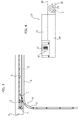
- FIG. 3 shows an embodiment of the invention and in particular the distinctive arrangement of the gear motor whose components are generally indicated with 6 in figure 6 .
- the configuration is such that the gear motor may be advantageously installed in proximity of the guide 5 adjacent to the horizontal shaft 7 carrying the torsion springs.
- the electric motor indicated with 9 and positioned horizontally, actuates - by means of a worm screw 10 - a vertical axis helical wheel 11 on which there is fitted a grooved output shaft 12 which controls the movement of the drive carrier 4 along the guide 5, through a flexible transmission (not represented in that conventional).
- the output shaft 12 projects slightly below the radial overall dimension of the electric motor 9.
- the gear motor 6 is housed in a box 13 having a flattened configuration and a small vertical overall dimension, for example a maximum thickness of the order of about 70-90 mm., so as to allow the installation thereof in line with the horizontal shaft 7, i.e. at a level or height substantially corresponding to that of the horizontal shaft 7, near the latter as represented in figure 3 and in larger detail in figure 10 .
- the box of the gear motor 6 may be traversed or not traversed by the horizontal shaft 7.
- this configuration enables the installation of the gear motor 6 close to the horizontal shaft 7 even in cases where there is little vertical space C available between the ceiling of the area where the sectional door is applied, indicated with S, and the upper panel/s 2 of the sectional door 1 when the latter is arranged in closing position.
- the box 13 is made up of a lower half-shell 14 and an upper half-shell 15, part of which was omitted in the illustration to show the electric motor 9 with the relative transformer 16.
- the output shaft 12 projects into a recess 17 of the upper half-shell 15, which also serves as a seat for the guide 5.
- the box 13 has a pair of appendages 18 carrying respective horizontal bushings 19 that can be opened by removing respective lower blocks 20.
- the bushings 19 have the function of enabling assembling the box 13, and thus the gear motor 6, directly on the horizontal shaft 7: it is sufficient to remove and then apply the lower boxes 20 to assemble.
- the box 13 may initially rotate on the horizontal shaft 7, so as to simplify the subsequent assembly of the guide 5.
- the box 13 may be fixed to the structure of the area delimited by the doorway 3, and this fixing may be such that the box 13 serves as a support for the horizontal shaft 7, which thus does not require further means for retention by means of brackets or the like, which may thus be eliminated.
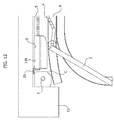
- the box of the gear motor may be installed in a space C autonomously, i.e. independently with respect to the horizontal shaft 7, but still at a level substantially corresponding to that of such horizontal shaft, for example as represented in figure 11 or in figure 12 .
- the box, indicated with 13A does not have the appendages 18 with the bushings 19 and it simply projects frontwards to the horizontal shaft 7, at the level thereof as mentioned, but without being traversed by it.
- the application of the box 13A is obtained in the case of figure 11 by means of at least one bracket 24 fixed to the architrave that delimits the doorway 3, and in the case of figure 12 through at least one attachment 25 fixed to the ceiling S.
- the carrier 4 may be configured so as to enable the attachment of the flexible transmission, actuated by the gear motor 6 and connected to the upper panel 2 of the door 1, selectively on one side or on the opposite side.
- Figure 7 schematically shows this configuration, in which the carrier 4 (not visible in that contained in the guide 5) is provided - at the opposite ends thereof - with two appendages 21, 22 symmetrically arranged on opposite sides with respect to the centre-line of the carrier indicated with P.
- one or the other appendage 21, 22 may be connected to an arm 23 in turn connected to the flexible transmission.
- the carrier 4 may be provided with a single appendage 21 removably fixed at one end thereof, as indicated with a solid line in figure 8 , or at the opposite end as indicated with a dashed line in the same figure, for attachment to the arm 23 respectively on one side or the other of the carrier 4.
- Another alternative consists in making the carrier 4 disassemblable from the guide 5, so as to rotate it by 180° for engaging the arm 23 to the appendage 21 on one side or on the opposite side.
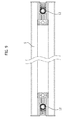
- Figure 9 shows a further alternative solution according to which the guide 5 is obtained in a symmetrical fashion, so as to enable the assembly of the gear motor 6 indistinctly in the innovative position of fig. 3 (as represented on the right side of fig. 8 ) or also as in fig. 1 just like in the prior art solutions (as represented on the right side of fig. 8 ).
Landscapes
- Power-Operated Mechanisms For Wings (AREA)
Applications Claiming Priority (1)
| Application Number | Priority Date | Filing Date | Title |
|---|---|---|---|
| ITUB2015A003562A ITUB20153562A1 (it) | 2015-09-11 | 2015-09-11 | Sistema di azionamento di una porta sezionale |
Publications (2)
| Publication Number | Publication Date |
|---|---|
| EP3141686A1 true EP3141686A1 (fr) | 2017-03-15 |
| EP3141686B1 EP3141686B1 (fr) | 2023-06-28 |
Family
ID=54843994
Family Applications (1)
| Application Number | Title | Priority Date | Filing Date |
|---|---|---|---|
| EP16188139.6A Active EP3141686B1 (fr) | 2015-09-11 | 2016-09-09 | Systeme d'entraînement pour une porte sectionnelle |
Country Status (2)
| Country | Link |
|---|---|
| EP (1) | EP3141686B1 (fr) |
| IT (1) | ITUB20153562A1 (fr) |
Citations (5)
| Publication number | Priority date | Publication date | Assignee | Title |
|---|---|---|---|---|
| US3478469A (en) * | 1968-07-02 | 1969-11-18 | Cyrus L Estes | Door moving mechanism |
| EP0939189A2 (fr) * | 1998-02-26 | 1999-09-01 | P & D Group Services Ltd. | Mécanisme de commande à distance pour porte |
| WO2004038162A1 (fr) * | 2002-10-25 | 2004-05-06 | Anzon Autodoor Limited | Groupe d'entrainement de portes automatiques |
| US20140027391A1 (en) | 2012-07-24 | 2014-01-30 | Curtis P. Menning | Barrier operator and chassis |
| US20150013229A1 (en) * | 2013-07-14 | 2015-01-15 | Eddy Shalom | Safety enhanced design of rail type garage door opener with over the door drive assembly |
-
2015
- 2015-09-11 IT ITUB2015A003562A patent/ITUB20153562A1/it unknown
-
2016
- 2016-09-09 EP EP16188139.6A patent/EP3141686B1/fr active Active
Patent Citations (5)
| Publication number | Priority date | Publication date | Assignee | Title |
|---|---|---|---|---|
| US3478469A (en) * | 1968-07-02 | 1969-11-18 | Cyrus L Estes | Door moving mechanism |
| EP0939189A2 (fr) * | 1998-02-26 | 1999-09-01 | P & D Group Services Ltd. | Mécanisme de commande à distance pour porte |
| WO2004038162A1 (fr) * | 2002-10-25 | 2004-05-06 | Anzon Autodoor Limited | Groupe d'entrainement de portes automatiques |
| US20140027391A1 (en) | 2012-07-24 | 2014-01-30 | Curtis P. Menning | Barrier operator and chassis |
| US20150013229A1 (en) * | 2013-07-14 | 2015-01-15 | Eddy Shalom | Safety enhanced design of rail type garage door opener with over the door drive assembly |
Also Published As
| Publication number | Publication date |
|---|---|
| EP3141686B1 (fr) | 2023-06-28 |
| ITUB20153562A1 (it) | 2017-03-11 |
Similar Documents
| Publication | Publication Date | Title |
|---|---|---|
| US7246465B2 (en) | Vehicle door module with support panel having integral stand-offs | |
| US9163448B2 (en) | Window regulator | |
| JP6384292B2 (ja) | 車両ドアモジュール | |
| CN115898194B (zh) | 车窗调节器 | |
| US20180328096A1 (en) | Window regulator | |
| GB2299824A (en) | Assembling motor vehicle doors | |
| JP2025170085A (ja) | ウインドレギュレータ及びガイドレールの取付け方法 | |
| JP6247227B2 (ja) | 開閉体開閉装置 | |
| JP2017137014A (ja) | 可動ホーム柵 | |
| EP3141686B1 (fr) | Systeme d'entraînement pour une porte sectionnelle | |
| JP6811142B2 (ja) | ウインドレギュレータ | |
| JP6739476B2 (ja) | ケーブル配索構造およびこれを用いた窓ガラス昇降装置 | |
| CN102009582B (zh) | 具有电动拉门的车辆的操作缆线的布缆构造 | |
| JP2019190229A (ja) | 対象物移動装置及び窓ガラス昇降装置 | |
| JP6393065B2 (ja) | ウィンドレギュレータ装置 | |
| JP6489256B2 (ja) | 可動ホーム柵 | |
| JP6435823B2 (ja) | スライドドアモジュール | |
| JP7233352B2 (ja) | 移動装置および窓ガラス昇降装置 | |
| WO2015115638A1 (fr) | Lève-vitre | |
| JP4234741B2 (ja) | スライドドア用給電装置 | |
| JP6348323B2 (ja) | ウィンドレギュレータ装置 | |
| JP2008030716A (ja) | スライドドア用給電装置 | |
| KR970006821Y1 (ko) | 차량도어의 글래스홀더 | |
| JP2025018714A (ja) | 扉スライド装置、および電動スライド扉 | |
| CN119195607A (zh) | 车窗调节器 |
Legal Events
| Date | Code | Title | Description |
|---|---|---|---|
| PUAI | Public reference made under article 153(3) epc to a published international application that has entered the european phase |
Free format text: ORIGINAL CODE: 0009012 |
|
| STAA | Information on the status of an ep patent application or granted ep patent |
Free format text: STATUS: THE APPLICATION HAS BEEN PUBLISHED |
|
| AK | Designated contracting states |
Kind code of ref document: A1 Designated state(s): AL AT BE BG CH CY CZ DE DK EE ES FI FR GB GR HR HU IE IS IT LI LT LU LV MC MK MT NL NO PL PT RO RS SE SI SK SM TR |
|
| AX | Request for extension of the european patent |
Extension state: BA ME |
|
| STAA | Information on the status of an ep patent application or granted ep patent |
Free format text: STATUS: REQUEST FOR EXAMINATION WAS MADE |
|
| 17P | Request for examination filed |
Effective date: 20170901 |
|
| RBV | Designated contracting states (corrected) |
Designated state(s): AL AT BE BG CH CY CZ DE DK EE ES FI FR GB GR HR HU IE IS IT LI LT LU LV MC MK MT NL NO PL PT RO RS SE SI SK SM TR |
|
| STAA | Information on the status of an ep patent application or granted ep patent |
Free format text: STATUS: EXAMINATION IS IN PROGRESS |
|
| 17Q | First examination report despatched |
Effective date: 20181017 |
|
| RAP1 | Party data changed (applicant data changed or rights of an application transferred) |
Owner name: KEY AUTOMATION S.R.L. |
|
| GRAP | Despatch of communication of intention to grant a patent |
Free format text: ORIGINAL CODE: EPIDOSNIGR1 |
|
| STAA | Information on the status of an ep patent application or granted ep patent |
Free format text: STATUS: GRANT OF PATENT IS INTENDED |
|
| INTG | Intention to grant announced |
Effective date: 20230110 |
|
| GRAS | Grant fee paid |
Free format text: ORIGINAL CODE: EPIDOSNIGR3 |
|
| GRAA | (expected) grant |
Free format text: ORIGINAL CODE: 0009210 |
|
| STAA | Information on the status of an ep patent application or granted ep patent |
Free format text: STATUS: THE PATENT HAS BEEN GRANTED |
|
| P01 | Opt-out of the competence of the unified patent court (upc) registered |
Effective date: 20230420 |
|
| AK | Designated contracting states |
Kind code of ref document: B1 Designated state(s): AL AT BE BG CH CY CZ DE DK EE ES FI FR GB GR HR HU IE IS IT LI LT LU LV MC MK MT NL NO PL PT RO RS SE SI SK SM TR |
|
| REG | Reference to a national code |
Ref country code: CH Ref legal event code: EP |
|
| REG | Reference to a national code |
Ref country code: AT Ref legal event code: REF Ref document number: 1582817 Country of ref document: AT Kind code of ref document: T Effective date: 20230715 |
|
| REG | Reference to a national code |
Ref country code: IE Ref legal event code: FG4D |
|
| REG | Reference to a national code |
Ref country code: DE Ref legal event code: R096 Ref document number: 602016080589 Country of ref document: DE |
|
| REG | Reference to a national code |
Ref country code: LT Ref legal event code: MG9D |
|
| PG25 | Lapsed in a contracting state [announced via postgrant information from national office to epo] |
Ref country code: SE Free format text: LAPSE BECAUSE OF FAILURE TO SUBMIT A TRANSLATION OF THE DESCRIPTION OR TO PAY THE FEE WITHIN THE PRESCRIBED TIME-LIMIT Effective date: 20230628 Ref country code: NO Free format text: LAPSE BECAUSE OF FAILURE TO SUBMIT A TRANSLATION OF THE DESCRIPTION OR TO PAY THE FEE WITHIN THE PRESCRIBED TIME-LIMIT Effective date: 20230928 |
|
| REG | Reference to a national code |
Ref country code: NL Ref legal event code: MP Effective date: 20230628 |
|
| REG | Reference to a national code |
Ref country code: AT Ref legal event code: MK05 Ref document number: 1582817 Country of ref document: AT Kind code of ref document: T Effective date: 20230628 |
|
| PG25 | Lapsed in a contracting state [announced via postgrant information from national office to epo] |
Ref country code: RS Free format text: LAPSE BECAUSE OF FAILURE TO SUBMIT A TRANSLATION OF THE DESCRIPTION OR TO PAY THE FEE WITHIN THE PRESCRIBED TIME-LIMIT Effective date: 20230628 Ref country code: NL Free format text: LAPSE BECAUSE OF FAILURE TO SUBMIT A TRANSLATION OF THE DESCRIPTION OR TO PAY THE FEE WITHIN THE PRESCRIBED TIME-LIMIT Effective date: 20230628 Ref country code: LV Free format text: LAPSE BECAUSE OF FAILURE TO SUBMIT A TRANSLATION OF THE DESCRIPTION OR TO PAY THE FEE WITHIN THE PRESCRIBED TIME-LIMIT Effective date: 20230628 Ref country code: LT Free format text: LAPSE BECAUSE OF FAILURE TO SUBMIT A TRANSLATION OF THE DESCRIPTION OR TO PAY THE FEE WITHIN THE PRESCRIBED TIME-LIMIT Effective date: 20230628 Ref country code: HR Free format text: LAPSE BECAUSE OF FAILURE TO SUBMIT A TRANSLATION OF THE DESCRIPTION OR TO PAY THE FEE WITHIN THE PRESCRIBED TIME-LIMIT Effective date: 20230628 Ref country code: GR Free format text: LAPSE BECAUSE OF FAILURE TO SUBMIT A TRANSLATION OF THE DESCRIPTION OR TO PAY THE FEE WITHIN THE PRESCRIBED TIME-LIMIT Effective date: 20230929 |
|
| PG25 | Lapsed in a contracting state [announced via postgrant information from national office to epo] |
Ref country code: FI Free format text: LAPSE BECAUSE OF FAILURE TO SUBMIT A TRANSLATION OF THE DESCRIPTION OR TO PAY THE FEE WITHIN THE PRESCRIBED TIME-LIMIT Effective date: 20230628 |
|
| PG25 | Lapsed in a contracting state [announced via postgrant information from national office to epo] |
Ref country code: SK Free format text: LAPSE BECAUSE OF FAILURE TO SUBMIT A TRANSLATION OF THE DESCRIPTION OR TO PAY THE FEE WITHIN THE PRESCRIBED TIME-LIMIT Effective date: 20230628 |
|
| PG25 | Lapsed in a contracting state [announced via postgrant information from national office to epo] |
Ref country code: ES Free format text: LAPSE BECAUSE OF FAILURE TO SUBMIT A TRANSLATION OF THE DESCRIPTION OR TO PAY THE FEE WITHIN THE PRESCRIBED TIME-LIMIT Effective date: 20230628 |
|
| PG25 | Lapsed in a contracting state [announced via postgrant information from national office to epo] |
Ref country code: IS Free format text: LAPSE BECAUSE OF FAILURE TO SUBMIT A TRANSLATION OF THE DESCRIPTION OR TO PAY THE FEE WITHIN THE PRESCRIBED TIME-LIMIT Effective date: 20231028 |
|
| PG25 | Lapsed in a contracting state [announced via postgrant information from national office to epo] |
Ref country code: SM Free format text: LAPSE BECAUSE OF FAILURE TO SUBMIT A TRANSLATION OF THE DESCRIPTION OR TO PAY THE FEE WITHIN THE PRESCRIBED TIME-LIMIT Effective date: 20230628 Ref country code: SK Free format text: LAPSE BECAUSE OF FAILURE TO SUBMIT A TRANSLATION OF THE DESCRIPTION OR TO PAY THE FEE WITHIN THE PRESCRIBED TIME-LIMIT Effective date: 20230628 Ref country code: RO Free format text: LAPSE BECAUSE OF FAILURE TO SUBMIT A TRANSLATION OF THE DESCRIPTION OR TO PAY THE FEE WITHIN THE PRESCRIBED TIME-LIMIT Effective date: 20230628 Ref country code: PT Free format text: LAPSE BECAUSE OF FAILURE TO SUBMIT A TRANSLATION OF THE DESCRIPTION OR TO PAY THE FEE WITHIN THE PRESCRIBED TIME-LIMIT Effective date: 20231030 Ref country code: IS Free format text: LAPSE BECAUSE OF FAILURE TO SUBMIT A TRANSLATION OF THE DESCRIPTION OR TO PAY THE FEE WITHIN THE PRESCRIBED TIME-LIMIT Effective date: 20231028 Ref country code: ES Free format text: LAPSE BECAUSE OF FAILURE TO SUBMIT A TRANSLATION OF THE DESCRIPTION OR TO PAY THE FEE WITHIN THE PRESCRIBED TIME-LIMIT Effective date: 20230628 Ref country code: EE Free format text: LAPSE BECAUSE OF FAILURE TO SUBMIT A TRANSLATION OF THE DESCRIPTION OR TO PAY THE FEE WITHIN THE PRESCRIBED TIME-LIMIT Effective date: 20230628 Ref country code: CZ Free format text: LAPSE BECAUSE OF FAILURE TO SUBMIT A TRANSLATION OF THE DESCRIPTION OR TO PAY THE FEE WITHIN THE PRESCRIBED TIME-LIMIT Effective date: 20230628 Ref country code: AT Free format text: LAPSE BECAUSE OF FAILURE TO SUBMIT A TRANSLATION OF THE DESCRIPTION OR TO PAY THE FEE WITHIN THE PRESCRIBED TIME-LIMIT Effective date: 20230628 |
|
| PG25 | Lapsed in a contracting state [announced via postgrant information from national office to epo] |
Ref country code: PL Free format text: LAPSE BECAUSE OF FAILURE TO SUBMIT A TRANSLATION OF THE DESCRIPTION OR TO PAY THE FEE WITHIN THE PRESCRIBED TIME-LIMIT Effective date: 20230628 |
|
| REG | Reference to a national code |
Ref country code: DE Ref legal event code: R097 Ref document number: 602016080589 Country of ref document: DE |
|
| PG25 | Lapsed in a contracting state [announced via postgrant information from national office to epo] |
Ref country code: DK Free format text: LAPSE BECAUSE OF FAILURE TO SUBMIT A TRANSLATION OF THE DESCRIPTION OR TO PAY THE FEE WITHIN THE PRESCRIBED TIME-LIMIT Effective date: 20230628 |
|
| REG | Reference to a national code |
Ref country code: CH Ref legal event code: PL |
|
| PLBE | No opposition filed within time limit |
Free format text: ORIGINAL CODE: 0009261 |
|
| STAA | Information on the status of an ep patent application or granted ep patent |
Free format text: STATUS: NO OPPOSITION FILED WITHIN TIME LIMIT |
|
| PG25 | Lapsed in a contracting state [announced via postgrant information from national office to epo] |
Ref country code: LU Free format text: LAPSE BECAUSE OF NON-PAYMENT OF DUE FEES Effective date: 20230909 |
|
| REG | Reference to a national code |
Ref country code: BE Ref legal event code: MM Effective date: 20230930 |
|
| GBPC | Gb: european patent ceased through non-payment of renewal fee |
Effective date: 20230928 |
|
| PG25 | Lapsed in a contracting state [announced via postgrant information from national office to epo] |
Ref country code: LU Free format text: LAPSE BECAUSE OF NON-PAYMENT OF DUE FEES Effective date: 20230909 Ref country code: IT Free format text: LAPSE BECAUSE OF FAILURE TO SUBMIT A TRANSLATION OF THE DESCRIPTION OR TO PAY THE FEE WITHIN THE PRESCRIBED TIME-LIMIT Effective date: 20230628 Ref country code: MC Free format text: LAPSE BECAUSE OF FAILURE TO SUBMIT A TRANSLATION OF THE DESCRIPTION OR TO PAY THE FEE WITHIN THE PRESCRIBED TIME-LIMIT Effective date: 20230628 |
|
| 26N | No opposition filed |
Effective date: 20240402 |
|
| REG | Reference to a national code |
Ref country code: IE Ref legal event code: MM4A |
|
| PG25 | Lapsed in a contracting state [announced via postgrant information from national office to epo] |
Ref country code: IE Free format text: LAPSE BECAUSE OF NON-PAYMENT OF DUE FEES Effective date: 20230909 |
|
| PG25 | Lapsed in a contracting state [announced via postgrant information from national office to epo] |
Ref country code: GB Free format text: LAPSE BECAUSE OF NON-PAYMENT OF DUE FEES Effective date: 20230928 |
|
| PG25 | Lapsed in a contracting state [announced via postgrant information from national office to epo] |
Ref country code: CH Free format text: LAPSE BECAUSE OF NON-PAYMENT OF DUE FEES Effective date: 20230930 |
|
| PG25 | Lapsed in a contracting state [announced via postgrant information from national office to epo] |
Ref country code: IE Free format text: LAPSE BECAUSE OF NON-PAYMENT OF DUE FEES Effective date: 20230909 Ref country code: GB Free format text: LAPSE BECAUSE OF NON-PAYMENT OF DUE FEES Effective date: 20230928 Ref country code: CH Free format text: LAPSE BECAUSE OF NON-PAYMENT OF DUE FEES Effective date: 20230930 Ref country code: SI Free format text: LAPSE BECAUSE OF FAILURE TO SUBMIT A TRANSLATION OF THE DESCRIPTION OR TO PAY THE FEE WITHIN THE PRESCRIBED TIME-LIMIT Effective date: 20230628 |
|
| PG25 | Lapsed in a contracting state [announced via postgrant information from national office to epo] |
Ref country code: BE Free format text: LAPSE BECAUSE OF NON-PAYMENT OF DUE FEES Effective date: 20230930 |
|
| PG25 | Lapsed in a contracting state [announced via postgrant information from national office to epo] |
Ref country code: BG Free format text: LAPSE BECAUSE OF FAILURE TO SUBMIT A TRANSLATION OF THE DESCRIPTION OR TO PAY THE FEE WITHIN THE PRESCRIBED TIME-LIMIT Effective date: 20230628 |
|
| PG25 | Lapsed in a contracting state [announced via postgrant information from national office to epo] |
Ref country code: BG Free format text: LAPSE BECAUSE OF FAILURE TO SUBMIT A TRANSLATION OF THE DESCRIPTION OR TO PAY THE FEE WITHIN THE PRESCRIBED TIME-LIMIT Effective date: 20230628 |
|
| PG25 | Lapsed in a contracting state [announced via postgrant information from national office to epo] |
Ref country code: CY Free format text: LAPSE BECAUSE OF FAILURE TO SUBMIT A TRANSLATION OF THE DESCRIPTION OR TO PAY THE FEE WITHIN THE PRESCRIBED TIME-LIMIT; INVALID AB INITIO Effective date: 20160909 |
|
| PG25 | Lapsed in a contracting state [announced via postgrant information from national office to epo] |
Ref country code: HU Free format text: LAPSE BECAUSE OF FAILURE TO SUBMIT A TRANSLATION OF THE DESCRIPTION OR TO PAY THE FEE WITHIN THE PRESCRIBED TIME-LIMIT; INVALID AB INITIO Effective date: 20160909 |
|
| PGFP | Annual fee paid to national office [announced via postgrant information from national office to epo] |
Ref country code: DE Payment date: 20250924 Year of fee payment: 10 |
|
| PGFP | Annual fee paid to national office [announced via postgrant information from national office to epo] |
Ref country code: FR Payment date: 20250911 Year of fee payment: 10 |
|
| PG25 | Lapsed in a contracting state [announced via postgrant information from national office to epo] |
Ref country code: TR Free format text: LAPSE BECAUSE OF FAILURE TO SUBMIT A TRANSLATION OF THE DESCRIPTION OR TO PAY THE FEE WITHIN THE PRESCRIBED TIME-LIMIT Effective date: 20230628 |