EP3141697A2 - Pompe excentrique, en particulier pompe d'alimentation pour solutions aqueuses d'uree et dispositif d'alimentation comprenant une pompe excentrique - Google Patents
Pompe excentrique, en particulier pompe d'alimentation pour solutions aqueuses d'uree et dispositif d'alimentation comprenant une pompe excentrique Download PDFInfo
- Publication number
- EP3141697A2 EP3141697A2 EP16001790.1A EP16001790A EP3141697A2 EP 3141697 A2 EP3141697 A2 EP 3141697A2 EP 16001790 A EP16001790 A EP 16001790A EP 3141697 A2 EP3141697 A2 EP 3141697A2
- Authority
- EP
- European Patent Office
- Prior art keywords
- eccentric
- pump
- disc
- sealing
- conveyor disc
- Prior art date
- Legal status (The legal status is an assumption and is not a legal conclusion. Google has not performed a legal analysis and makes no representation as to the accuracy of the status listed.)
- Withdrawn
Links
Images




Classifications
-
- F—MECHANICAL ENGINEERING; LIGHTING; HEATING; WEAPONS; BLASTING
- F04—POSITIVE - DISPLACEMENT MACHINES FOR LIQUIDS; PUMPS FOR LIQUIDS OR ELASTIC FLUIDS
- F04C—ROTARY-PISTON, OR OSCILLATING-PISTON, POSITIVE-DISPLACEMENT MACHINES FOR LIQUIDS; ROTARY-PISTON, OR OSCILLATING-PISTON, POSITIVE-DISPLACEMENT PUMPS
- F04C2/00—Rotary-piston machines or pumps
- F04C2/30—Rotary-piston machines or pumps having the characteristics covered by two or more groups F04C2/02, F04C2/08, F04C2/22, F04C2/24 or having the characteristics covered by one of these groups together with some other type of movement between co-operating members
- F04C2/34—Rotary-piston machines or pumps having the characteristics covered by two or more groups F04C2/02, F04C2/08, F04C2/22, F04C2/24 or having the characteristics covered by one of these groups together with some other type of movement between co-operating members having the movement defined in groups F04C2/08 or F04C2/22 and relative reciprocation between the co-operating members
- F04C2/356—Rotary-piston machines or pumps having the characteristics covered by two or more groups F04C2/02, F04C2/08, F04C2/22, F04C2/24 or having the characteristics covered by one of these groups together with some other type of movement between co-operating members having the movement defined in groups F04C2/08 or F04C2/22 and relative reciprocation between the co-operating members with vanes reciprocating with respect to the outer member
-
- F—MECHANICAL ENGINEERING; LIGHTING; HEATING; WEAPONS; BLASTING
- F01—MACHINES OR ENGINES IN GENERAL; ENGINE PLANTS IN GENERAL; STEAM ENGINES
- F01C—ROTARY-PISTON OR OSCILLATING-PISTON MACHINES OR ENGINES
- F01C21/00—Component parts, details or accessories not provided for in groups F01C1/00 - F01C20/00
- F01C21/10—Outer members for co-operation with rotary pistons; Casings
- F01C21/104—Stators; Members defining the outer boundaries of the working chamber
- F01C21/108—Stators; Members defining the outer boundaries of the working chamber with an axial surface, e.g. side plates
-
- F—MECHANICAL ENGINEERING; LIGHTING; HEATING; WEAPONS; BLASTING
- F04—POSITIVE - DISPLACEMENT MACHINES FOR LIQUIDS; PUMPS FOR LIQUIDS OR ELASTIC FLUIDS
- F04C—ROTARY-PISTON, OR OSCILLATING-PISTON, POSITIVE-DISPLACEMENT MACHINES FOR LIQUIDS; ROTARY-PISTON, OR OSCILLATING-PISTON, POSITIVE-DISPLACEMENT PUMPS
- F04C14/00—Control of, monitoring of, or safety arrangements for, machines, pumps or pumping installations
- F04C14/28—Safety arrangements; Monitoring
-
- F—MECHANICAL ENGINEERING; LIGHTING; HEATING; WEAPONS; BLASTING
- F04—POSITIVE - DISPLACEMENT MACHINES FOR LIQUIDS; PUMPS FOR LIQUIDS OR ELASTIC FLUIDS
- F04C—ROTARY-PISTON, OR OSCILLATING-PISTON, POSITIVE-DISPLACEMENT MACHINES FOR LIQUIDS; ROTARY-PISTON, OR OSCILLATING-PISTON, POSITIVE-DISPLACEMENT PUMPS
- F04C15/00—Component parts, details or accessories of machines, pumps or pumping installations, not provided for in groups F04C2/00 - F04C14/00
- F04C15/0003—Sealing arrangements in rotary-piston machines or pumps
- F04C15/0023—Axial sealings for working fluid
- F04C15/0026—Elements specially adapted for sealing of the lateral faces of intermeshing-engagement type machines or pumps, e.g. gear machines or pumps
-
- F—MECHANICAL ENGINEERING; LIGHTING; HEATING; WEAPONS; BLASTING
- F04—POSITIVE - DISPLACEMENT MACHINES FOR LIQUIDS; PUMPS FOR LIQUIDS OR ELASTIC FLUIDS
- F04C—ROTARY-PISTON, OR OSCILLATING-PISTON, POSITIVE-DISPLACEMENT MACHINES FOR LIQUIDS; ROTARY-PISTON, OR OSCILLATING-PISTON, POSITIVE-DISPLACEMENT PUMPS
- F04C5/00—Rotary-piston machines or pumps with the working-chamber walls at least partly resiliently deformable
-
- F—MECHANICAL ENGINEERING; LIGHTING; HEATING; WEAPONS; BLASTING
- F04—POSITIVE - DISPLACEMENT MACHINES FOR LIQUIDS; PUMPS FOR LIQUIDS OR ELASTIC FLUIDS
- F04C—ROTARY-PISTON, OR OSCILLATING-PISTON, POSITIVE-DISPLACEMENT MACHINES FOR LIQUIDS; ROTARY-PISTON, OR OSCILLATING-PISTON, POSITIVE-DISPLACEMENT PUMPS
- F04C2210/00—Fluid
- F04C2210/10—Fluid working
- F04C2210/1083—Urea
Definitions
- the invention relates to an eccentric pump, in particular a feed pump for aqueous urea solutions, according to the preamble of claim 1 and a conveying device with such an eccentric pump according to the preamble of claim 12.
- a high-pressure pump which has an eccentric disc arranged in a pump housing. Their rotational movement is converted into a linear movement of a piston with which a reaching into the piston chamber diesel fuel can be strongly compressed. The thus compressed fuel is then pumped, for example, into a fuel reservoir of a diesel injection system.
- the pump is exposed to high mechanical and thermal loads as well as weather conditions.
- the invention is based on the object, with simple measures to provide an eccentric pump and a conveyor, which are suitable for use in a wide temperature range.
- the eccentric pump according to the invention is particularly suitable for conveying small and very small amounts of fluid. It is preferably as a feed pump used for aqueous urea solutions, which are injected into the exhaust gas line for the exhaust aftertreatment of diesel engines for the reduction of nitrogen oxides.
- the eccentric pump has a rotatably mounted and driven eccentric shaft in a pump housing, which drives the conveyor disc in the eccentric space in the pump housing.
- the conveyor disc which has a smaller diameter than the eccentric space, includes between its outer side and the outer ring surrounding it a sickle-shaped delivery chamber for receiving the fluid to be delivered.
- the crescent-shaped delivery chamber in this case runs in the circumferential direction and moves from the inlet connection, via which the fluid enters the delivery chamber, to the outlet connection, via which the fluid is discharged from the delivery chamber.
- the fluid to be delivered is in particular a liquid, preferably an aqueous urea solution.
- a liquid preferably an aqueous urea solution.
- gaseous fluids for example air
- the delivery chamber is bounded laterally by the elastic sealing disc, which is located in a compensation chamber in the pump housing.
- the sealing disc is subjected to a pressing force in a sealing or starting position in which the delivery chamber is closed in a flow-tight manner. Due to its elasticity, the sealing disk can elastically deform at a correspondingly high pressure of the fluid in the delivery chamber, in particular in such a way that the delivery chamber is enlarged by the expansion, but the fluid remains trapped. As soon as the pressure in the delivery chamber decreases, the sealing disc returns to its original position.
- the elasticity of the sealing disc makes it possible to compensate for an increase in volume of the fluid in the delivery chamber. For example, it takes up the volume of fluid in the transition from the liquid to the solid state Due to a freezing process, the sealing disc deforms in an elastic manner in the expansion chamber in the pump housing, in which the sealing disc is arranged. The increase in volume due to freezing of the fluid can thus be readily compensated for and does not lead to component damage. If the temperature rises above the freezing point, the fluid in the delivery chamber liquefies again, so that the sealing disc can return to the starting position due to the associated volume reduction under the effect of elasticity.
- the sealing force can be influenced, with which the sealing disc limits the delivery chamber laterally.
- the elasticity of the sealing disc is determined on the one hand by its inherent elasticity and on the other hand by the spring force of the spring element acting on it. But it may also be sufficient to arrange a sealing disc without or with only low intrinsic elasticity and to let the elastic behavior exclusively or largely determined by the spring element. In the event that no spring element is arranged in the compensation chamber, the elasticity derives exclusively from the inherent elasticity of the sealing disc.
- a spring element is for example a helical compression spring into consideration.
- a plurality of helical compression springs distributed over the circumference are arranged in the compensation chamber, which load the sealing disk in the direction of its sealing position.
- the spring element is designed as a plate spring, which has the advantage that over the circumference a uniform axial contact force acts on the sealing disc.
- the or the spring elements are based on the side facing away from the sealing disc on a housing inner wall of the compensation chamber. As a result, the spring action of the sealing disk given by the elasticity of the sealing disk itself interacts with the conveying force of the spring elements.
- At least one vent hole connected to the atmosphere opens into the compensation chamber. This ensures that with an expansion of the fluid and a deformation of the gasket in the expansion chamber into the gas located in the expansion chamber can escape. If the sealing washer returns to its initial position, gas can flow back into the expansion chamber via the venting bore.
- the vent hole can be closed in an advantageous development with a filter element or a vapor membrane to prevent contamination.
- the compensation chamber has no vent hole.
- the volume of gas trapped in the expansion chamber serves as a gas spring which acts on the sealing disk and forces it into the sealing or starting position.
- the sealing disc has an axially extending sealing collar, which is supported on a wall of the expansion chamber.
- the sealing collar is preferably formed integrally with the sealing disc and allows radial support on a housing-side component over a larger support surface.
- the sealing disc is clamped at its outer and / or inner peripheral edge between parts of the eccentric pump. This makes possible a simple installation of the sealing washer without additional fasteners.
- the sealing collar advantageously covers a sealing ring, which is inserted into a groove in the wall of the expansion chamber. As a result, leaking to the outside is prevented when lifting the sealing disc. Rather, the medium is removed via the vent hole, which forms a leakage hole in this case.
- Another sealing ring can be inserted into the outer ring and covered by the disc-shaped part of the sealing disc.
- the sealing rings additionally increase the sealing effect and prevent leakage currents along the side surface of the conveyor disc or outer ring and along the inner wall of the compensation chamber.
- the housing-side outer ring which surrounds the conveyor disc and the delivery chamber bounded radially outwardly, on its radially inner inner side an elastomer layer.
- the conveyor disc In the eccentric movement, the conveyor disc always has contact with the elastomer layer which deforms at least slightly radially and at the same time allows the movement of the conveyor disc in the circumferential direction with low friction.
- a circumferential, concave depression which is covered by the elastomer layer, is introduced on the inside of the outer ring.
- the evasive movement serves for tolerance compensation of the components. Diameter tolerances can be compensated. Since the volumetric efficiency depends strongly on the leakage between the outer ring and the conveyor disc, the elastomer layer also serves to seal. In a purely metallic seal between the outer ring and the conveyor disc, the contact surfaces and the squareness must be very accurate be made. The elastomeric layer reliably compensates for the irregularities and tolerances in a simple manner.
- the conveyor disc is provided in the peripheral side with a radial recess.
- at least one barrier wing is used, which is subjected to a force radially outward.
- the blocking wing abuts against the inside of the outer ring or the elastomer layer on the outer ring between the inlet and outlet connection and separates the inlet connection from the outlet connection in a flow-tight manner.
- the barrier wing thus prevents unwanted direct overflow of the fluid between the inlet and outlet ports. In this way, it is ensured that the fluid guided into the delivery chamber via the inlet connection is conveyed in the circumferential direction within the delivery chamber to the outlet connection during a delivery movement of the delivery disc.
- the blocking wing can move in the recess in the radial direction and is advantageously pressed by at least one spring element against the inside of the outer ring or the elastomer layer. At the same time this ensures that during the movement of the conveyor disc, the blocking vanes perform a wobbling motion and with its outer end side can perform at least a small sliding movement in the segment between the inlet and outlet ports.
- the eccentric shaft has an eccentric, which is the carrier of the bearing on which the conveyor disc is arranged.
- the conveyor disc in the eccentric performs the eccentric relative to the longitudinal axis of the eccentric shaft movement. Due to the bearing, the eccentric shaft and the conveyor disc can perform a relative rotational movement to each other, so that the conveyor disc performs no rotation about its own axis, but only a small wobbling motion and rolls on the inside of the outer ring or the elastomer layer.
- the conveyor disc is preferably fixed on the housing via at least one positioning pin, which prevents rotation of the conveyor disc, but allows the tumbling motion.
- the positioning pin is received with sufficient clearance in a recess of the conveyor disc to allow the eccentric radial or wobble movement of the conveyor disc in the eccentric.
- the positioning pin protrudes through the recess and is held with projecting end portions on both sides of the conveyor disc in housing components.
- the recess in the conveyor disc advantageously has a width which is greater than the diameter of the positioning pin to allow the desired radial relative movement between the positioning pin and the conveyor disc.
- the spring element may be designed as an elastic element, for example an elastic ring, and ensure tolerance compensation as well as prestressing in the direction of the outer ring.
- the spring element may, in a further embodiment, also be formed as an annular spring spiral element. The spring element can also protect the eccentric pump and thus the system from hydraulic pressure spikes and overload because the spring force must be greater than the operating pressure. Ideally, the spring force should be about 20% to 30% higher than the operating pressure.
- the conveyor disc assumes a defined initial or zero position when it is not driven.
- the conveyor disc assumes a defined initial or zero position when it is not driven.
- Eccentric provided at least one latching device that holds the conveyor disc in the initial or zero position.
- the eccentric shaft is provided in the eccentric with a rotatably connected thereto component which occupies a certain angular position with respect to the eccentric shaft.
- This component is part of the locking device and cooperates with a housing-fixed locking element.
- the zero position for example for metering pumps, the eccentric pump can be defined.
- a locking disk is arranged on the eccentric shaft, which is associated with a housing-side locking element.
- the locking disk which is preferably formed integrally with the eccentric shaft, may have on its peripheral side a detent recess or a Rastabflachung.
- On the housing side protrudes a locking element in the locking position in the locking recess on the locking disc.
- the latching element is, for example, a ball, which is subjected to a force of a spring element in the latching position.
- the interaction of locking cam or latching recess and locking element takes place here in the radial direction.
- a Rastabflachung this forms a Rastplateau on the locking disc on which an associated locking element which is held on the housing, e.g. a role or a shoe, rests in the locked position.
- the latching elements may also be designed to act magnetically in the latching position, for example as a permanent magnet and a magnetically soft component cooperating with the permanent magnet.
- the permanent magnet is e.g. arranged on a locking cam on the eccentric shaft and exerts a magnetic force on the housing-side locking part, which is made of the soft magnetic material.
- the eccentric shaft of the permanent magnet runs past the associated locking member on the housing component, wherein the magnetic force acting between these components defines the desired locking position.
- a ring seal supported on the housing is arranged on at least one side surface of the conveyor disk.
- a ring seal supported on the housing is preferably arranged on both side surfaces of the conveyor disk.
- the ring seal or ring seals provide a fluid-tight seal against any fluid escaping from the delivery chamber and prevent the fluid from flowing radially inwardly toward the eccentric shaft.
- the ring seal is formed, for example, as a mechanical seal, which bears against the side surface of the conveyor disc.
- the ring seal is formed as a diaphragm seal, which engages in a circumferential groove on the side surface of the conveyor disc and is radially elastically compressed during the eccentric movement of the conveyor disc. The diaphragm allows the eccentric stroke of the conveyor disc without the diaphragm seal having to slide on the contact surfaces. This eliminates a sliding friction and hysteresis, which would be detrimental to the metering pump according to the invention.
- a penetrating, extending between the side surfaces connecting bore is introduced into the conveyor disc, which is assigned in at least one adjacent housing component, a leakage bore. Fluid, possibly exiting the delivery chamber and flowing radially inward along the side surface of the conveyor disc, can via the leakage bore in the housing component be derived.
- the connection bore through the conveyor disc in this case promotes leakage fluid from the opposite side surface of the conveyor disc to the introduced into the housing component leakage bore.
- a check valve is integrated in the outlet connection, which closes in the outlet direction and is mechanically opened by the conveyor disc.
- the check valve serves to secure the accumulator pressure on the pressure side of the eccentric pump, since the leakage of the eccentric pump could possibly be too long over time.
- the check valve is mechanically, for example by means of a pin, opened in order to be able to empty the pressure side when pumping back. If a check valve is not used, the eccentric pump can be operated in both directions. The pressure and suction side are swapped accordingly depending on the direction of rotation of the eccentric shaft.
- Another aspect of the invention relates to a conveying device, which is designed as a combination of an eccentric pump and an air pump.
- This combination makes it possible, for example, in addition to the promotion of aqueous urea solution also introduce an amount of air in the exhaust system for nitrogen oxide reduction.
- the eccentric pump of the conveyor is advantageously carried out as the eccentric pump according to the invention.
- the eccentric pump and the air pump are drivable according to a preferred embodiment of a common drive motor.
- the eccentric shaft of the eccentric pump and a drive shaft of the air pump can be arranged coaxially and can be coupled via a coupling element.
- Eccentric shaft and drive shaft are arranged axially one behind the other, so that the drive, for example, the eccentric shaft is also transmitted to the drive shaft or vice versa.
- the drive is preferably via an electric motor, such as a stepper motor.
- the air pump is identical or largely identical as the eccentric constructed. This makes it possible to arrange two eccentric pumps axially one behind the other and to couple the eccentric shafts in order to drive them via a common drive motor.
- Each pump is in this case provided with a pump housing, wherein the two pump housings can preferably be joined together.
- the air pump as an eccentric pump
- other embodiments are also possible, for example a design of the air pump as a spiral pump, whose conveying member is a spiral.
- the eccentric pump and the spiral pump are driven by a common drive motor.
- an eccentric pump 1 is shown in axial section, which is used for example as a feed pump for an aqueous urea solution, which is injected to reduce nitrogen oxides in the exhaust line of a diesel internal combustion engine.
- the eccentric pump 1 is designed as a very small quantity pump, which pumps flow rates in the range of about 5 ⁇ to about 100 ⁇ l (microliters).
- the eccentric pump 1 can of course be designed for larger flow rates.
- the eccentric pump 1 is assigned to drive an electric drive motor 2, which is arranged coaxially to the longitudinal axis of the eccentric pump 1 and flanged to a pump housing 8 of the eccentric pump.
- the drive motor 2 drives a rotatably mounted in the pump housing 8 in bearings 9, 10 eccentric shaft 3, which has an eccentric 4 about halfway.
- any suitable motor may be provided, such as a pneumatic or a hydraulic motor.
- the drive motor 2 is advantageously a stepper motor.
- the conveyor disc 6 is located between two disc-shaped rings 11, 12, against which the conveyor disc 6 rests with their side surfaces.
- the rings 11, 12 are axially secured by housing walls 13, 14, at the mutually facing inner sides of the rings 11,12 abut with their outer sides facing away from each other.
- the housing walls 13, 14 and the rings 11, 12 are connected to one another via a plurality of screws 15 and the like, which are distributed over the circumference. They are at a radial distance to the conveyor disc 6, which projects beyond the rings 11, 12 radially inwardly.
- the housing walls 13, 14 are provided on their inner side with a respective paragraph 51, 52, on which rest the rings 11, 12 with its inner cylindrical lateral surface 53, 54.
- the rings 11, 12 and the cylindrical housing walls 13, 14 advantageously have the same outer diameter, so that the pump housing 8 has a continuous approximately smooth outer side 55.
- the bearings 9, 10, which are preferably rolling bearings are housed in recesses 56, 57 in the inner sides of the housing walls 13, 14.
- the recesses 56, 57 are penetrated by the eccentric shaft 3, whose in Fig. 1 right end in the outside of the pump housing 8 and the housing wall 14 is located.
- the inner lateral surfaces 53, 54 of the rings 11, 12 bound the eccentric 7 radially outwardly, which is axially bounded by the radially inwardly beyond the rings 11, 12 projecting portions of the housing walls 13, 14.
- the conveyor disc 6 is surrounded at a distance by a cylindrical outer ring 17 which is covered on the inside by an elastomer layer 18. Between the conveyor disc 6 and the outer ring 17 and the elastomer layer 18, a sickle-shaped conveying chamber 16 is formed.
- the outer ring 17 has the same outer diameter as the rings 11, 12 and the housing walls 13, 14 and the same axial width as the conveyor disc 6. Der Outer ring 17 abuts the two rings 11, 12 and is axially penetrated by the screws 15.
- the elastomer layer 18 is formed elastically deformable and is compressed radially in sections during the rotation of the conveyor disc.
- the concave recess 19 on the inside of the outer ring 17 thus serves to partially receive the elastomer layer 18 in the case of a radially outwardly directed deformation.
- annular compensation chamber 20 In the ring 12 on the conveyor disc 6 side facing the conveyor disc 6 open annular compensation chamber 20 is inserted, which is coaxial with the eccentric shaft 3 and in which there is a sealing washer 21 which is pressed by at least one spring element 22 against the side surface of the conveyor disc 6 becomes.
- the sealing disc 21 covers the delivery chamber 16 axially, so that the fluid in the delivery chamber 16 is fluid-tightly received in this.
- the sealing disk 21 can elastically deform in the axial direction-in relation to the longitudinal axis 23 of the pump or the eccentric shaft-into the receiving space 20 when the fluid in the delivery chamber 16 experiences an increase in volume, in particular during freezing.
- the deformation of the sealing disk 21 into the compensation chamber 20 ensures that the components delimiting the delivery chamber 16 do not suffer any damage during freezing of the fluid and the concomitant increase in volume. As the frozen fluid liquefies, the volume increase decreases; Then the sealing disc 21 is pressed by the spring element 22 back into its initial or sealing position, in which the sealing disc 21 bears sealingly against the side surface of the conveyor disc 6.
- the compensation chamber 20 is provided so that it extends radially outwards to the level of the outer ring 17.
- the eccentric pump 1 has a built-in pressure relief valve, which improves the reliability of the eccentric pump 1 in an advantageous manner.
- the degradable overpressure may be from about 20% to about 30% above the operating pressure, i. the spring force is adjusted from about 20% to about 30% above the operating pressure (hydraulic pressure).
- the sealing disc 21 is thus not opened unintentionally.
- Typical operating pressures for SCR pumps are 8 to 10 bar.
- the sealing disc 21 extends radially outwardly to the outer side 55 of the pump housing 8 and is thereby clamped with its radially outer region axially between the ring 12 and the outer ring 17. Integral with the sealing disc 21, an axial cylindrical sealing collar 24 is formed, which bears against the radially inner cylindrical lateral surface 58 of the compensation chamber 20.
- the radially outer part of the sealing disc 21 covers a sealing ring 25, which lies in an annular groove 59 in a side surface 60 of the outer ring 17.
- the sealing collar 24 covers a further sealing ring 26, which is housed in an annular groove 61 in the compensation space 20 radially inwardly bounding lateral surface 58 in the ring 12.
- the two sealing rings 25, 26 prevent leakage of the fluid received in the delivery chamber 16 from reaching the outside.
- the compensation chamber 20 in the disc-shaped housing member 12 is connected via at least one, preferably distributed over a plurality of circumferentially spaced vent holes 27 to the atmosphere.
- the vent holes 27 extend from the expansion chamber 20 in the axial direction and penetrate both the ring 12 and the adjoining housing wall 14. About the vent holes 27 is for the case that when freezing the fluid in the delivery chamber 16, the sealing disc 21 in the expansion chamber 20 in elastically deformed, a venting of the expansion chamber 20 possible. Conversely, via the vent hole 27 gas or air flow back into the expansion chamber 20 as soon as the sealing disc 21 assumes its initial or sealing position again.
- vent holes 27 can be closed with a filter element or a vapor membrane to prevent contamination.
- the membrane is advantageously made of the material Goretex.
- the conveyor disc 6 is sealed against the two rings 11, 12 by a respective sealing ring 28, 28 ', which extends coaxially to the eccentric shaft 3.
- the conveyor disc 6 When rotating the eccentric shaft 3, the conveyor disc 6 performs a tumbling motion with radial deflection within the eccentric 7 with the eccentric 4 specified by the eccentric.
- the ring seals 28 used fixedly in the rings 11 and 12 are elastically deformed in the radial direction, wherein the sealing lips 67 ensure the tightness.
- At least one leakage bore 29 is introduced, which extends axially to the side surface 65 of the conveyor disc 6. It has distributed over the circumference a plurality of connecting holes 30 which penetrate the conveyor disc 6 axially.
- the leakage bore 29 opens into an annular channel 68, which is arranged coaxially to the eccentric shaft 3 and provided in the side surface 63 of the ring 11.
- the connecting bores 30 open into the annular channel 68.
- Another annular channel 68 ' is also provided in the side surface 63' of the ring 12.
- the connection holes 30 connect the two ring channels 68, 68 'together.
- Leakage fluid from the delivery chamber 16, which flows radially inward along one or both side surfaces between the conveyor disc 6 and the delimiting rings 11, 12, can be discharged via the connection bore 30 or possibly directly via the leakage bore 29 and to the (not shown) tank or returned to the suction port 31.
- the annular channels 68, 68 ' have a width such that the connecting bores 30 are always in line connection with the annular channels 68, 68' during the tumbling motion of the conveyor disc 6.
- leakage medium in each position of the conveyor disc 6 via the annular channels 68, 68 'and the leakage bore 29 are returned to the tank.
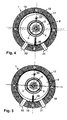
- the eccentric pump 1 is shown in radial section in different phases during one revolution of the eccentric shaft 3.
- the area between the conveyor disc 6 and the outer ring 17 is connected to an inlet or suction port 31 and to an outlet or pressure port 32.
- the inlet connection 31 the medium to be delivered is introduced from a tank into the eccentric chamber in the region of the crescent-shaped delivery chamber 16.
- the outlet port 32 which is arranged angularly offset from the inlet port 31, the discharge of the pressurized fluid takes place.
- the conveyor disc 6 has a smaller diameter than the eccentric 7. In one revolution of the eccentric shaft 3, the conveyor disc 6, which sits on the cam-shaped eccentric 4 of the eccentric shaft 3, driven annularly circumferentially within the eccentric 7 in the manner of a tumbling motion.
- the conveyor disc 6 is in each phase with a part of its lateral surface 69 sealingly against the elastomer layer 18 at. Between the lateral surface 69 of the conveyor disc 6 and the elastomer layer 18 is the crescent-shaped delivery chamber 16, which moves in the circumferential direction during the movement of the conveyor disc 6.
- the conveyor disc 6 is connected via the rolling bearing 5 with the eccentric shaft 3 and prevented by a positioning pin 33 from rotating.
- the longitudinal axis of the recess 34 is located in an axial plane of the conveyor disc 6.
- the width of the recess 34 is slightly larger than the diameter of the positioning pin 33.
- the conveyor disc 6 upon rotation of the Eccentric shaft 3 exercise the radial or tumbling motion reliable.
- the crescent-shaped delivery chamber 16 moves over the circumference of the eccentric pump, as from the Fig. 2 to 5 evident.
- the two ends of the positioning pin 33 are held in the rings 11, 12 ( FIGS. 7 and 8 ).
- the ring 11 has a blind bore 70 and the ring 12 has a blind bore 71 aligned with the blind bore 71. This allows the positioning pin 33 to be mounted easily.
- the positioning pin 33 can also be firmly inserted into one of the two rings 11, 12 and be freely movable in the conveyor disc 6 over a few millimeters.
- the conveyor disc 6 is provided on the circumference with a radial recess 35 into which a blocking wing 36 protrudes. It is loaded radially outward, preferably by at least one spring element 37, which is supported on the bottom 72 of the recess 35 and, for example, is a helical compression spring.
- the spring element 37 ensures that the locking wing 36 always bears sealingly against the elastomer layer 18 with its end face.
- the blocking wing 36 lies between the inlet connection 31 and the outlet connection 32 and ensures a flow-tight separation between the inlet and outlet connection in all phases of the circulation of the delivery chamber 16.
- the blocking wing 36 extends over the entire axial width of the delivery disc 6 (FIG. Fig. 6 ) and lies with its side edges sealingly on the side surfaces 63, 63 'of the rings 11, 12 at.
- the barrier wing 36 may also be hydraulically powered.
- at least one bore opens into the depression 35, via which the hydraulic pressure on the radially inner end face of the pressure side is discharged Sperrhoffls 36 acts. He is thus pressed depending on the prevailing pressure in its sealing position.
- a passage opening 73 which connects the recess 35 with the one connecting bore 30 of the conveyor disc 6 and serves as a pressure equalization.
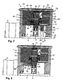
- the eccentric pump 1 is shown in a variant embodiment.
- the spring element is designed as a helical compression spring.
- the bottom 74 of the compensation chamber 20 is located over the circumference of the compensation chamber 20 extending recess 75, in which the plate spring 22 is supported with its edge.
- two mutually mutually arranged disc springs are provided, which load the sealing disc 21 evenly over its circumference axially.
- a recess 75 is provided for each helical compression spring 22 into which protrudes the one end of the helical compression spring, which is thereby properly secured in position.
- Another difference in the embodiment according to Fig. 7 lies in the arrangement of the two sealing rings 28. They are housed only in the annular grooves 62, 62 'of the rings 11, 12. Two of the four sealing lips 67 of the sealing rings 28, 28 'are sealingly against the side surfaces 65, 65' of the conveyor disc 6, while the other two sealing lips 67, the sealing rings 28, 28 'in the annular grooves 62, 62' are supported. The sealing lips 67 allow a reliable movement of the conveyor disc 6 during its movement.
- Fig. 7 is dispensed with the elastomer layer on the inside of the outer ring 17 so that the inside of the outer ring 17 directly limits the crescent-shaped delivery chamber 16.
- the conveyor disc 6 is supported via one or more spring elements 38 in the radial direction of the ball bearing 5, on the eccentric 4 of the eccentric shaft 3. The spring elements 38 load the conveyor disc 6 radially outward.
- the eccentric pump 1 is provided with a latching device 76 which provides a latching position in an initial or zero position of the conveyor disc 6.
- the latching device 76 has a housing-side locking element 40, 41 and a circumferential with the eccentric shaft 3 locking element, which in the embodiment according to Fig. 7 is designed as a locking plate 39, which is advantageously formed integrally with the eccentric shaft 3.
- a latching projection 40 which is arranged on the radially inner lateral surface 54 of the ring 12 and carrier of a detent ball 41 which is pressed radially by the force of a spring projection 40 supported in the locking element in a detent recess 77 n of the outside of the detent disk 39 ,
- the locking disk 39 has at its periphery only at one position the locking recess 77, in which the detent ball 41st is pressed.
- the locking device 76 is located in the eccentric 7 in the area between the conveyor disc 6 and the housing wall 14. During rotation of the eccentric shaft 3, the detent ball 41 is located under spring force on the circumference of the locking disc 39.
- the latching device 76 acts in the axial instead of the radial direction.
- the housing-side locking projection 40 is located in the transition between the housing wall 13 of the pump housing and the ring 11.
- the detent ball 41 is pressed axially against the side surface 65 of the conveyor disc 6 via the spring element.
- the detent recess 77 In the side surface 65 is the detent recess 77, in which the detent ball 41 engages in the initial or zero position of the conveyor disc 6.
- the latching device 76 may also be provided in the respective opposite part of the eccentric 7.
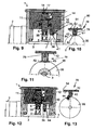
- FIGS. 9 and 10 a further embodiment of a latch 76 is shown, analogous to Fig. 7 is effective in the radial direction.
- the eccentric shaft 3 is provided with the detent disk 39, which has a flattening 42 on the circumference, which defines the detent position.
- a detent roller 41 ' Under spring force on the circumference of the locking disk 39 at.
- the detent roller 41 ' is provided at the radially inner end of a sliding body 78, which is displaceable in a radial guide 79. It is, for example, a sleeve which protrudes radially from the inner lateral surface 54 of the ring 12 and projects into the eccentric space 7 in the region between the conveyor disc 6 and the housing wall 14.
- the slide body 78 is provided on its side surface facing the lateral surface 54 with a centrally disposed recess 80, in which a compression spring 81 projects, which is supported on the lateral surface 54.
- the detent roller 41 ' extends axially and has a length which corresponds approximately to the axial thickness of the detent disk 39.
- Fig. 10 shows the detent roller 41 'is surrounded over part of its circumference by a half bearing shell 82 which is fixed to the inner end face of the sliding body 78. If the guide 79 is correspondingly long, it overlaps the detent roller 41 'axially so that it can not escape and remains in its desired position.
- the guide 79 is provided with a radially extending guide slot 83 through which a pin 84 mounted in the sliding body 78 projects. It ensures together with the guide slot 83 that the sliding body 78 is not rotated during its displacement movement, so that the detent roller 41 'is always aligned axially.
- the guide 79 and the sliding body 78 have square cross-section or outline, the guide slot 83 and the pin 84 are not necessary.
- the eccentric pump 1 is the same design as in the embodiment according to the Fig. 7 or 8 ,
- a sliding shoe 43 is held in the radial displacement guide 79, which rests on the outer circumference of the detent disk 39.
- the flattening 42 on the circumference of the locking disc 39 also defines in this embodiment, the locking position for the conveyor disc 6 in the locking or zero position.
- the locking disk 39 is provided on the eccentric shaft 3, that it defines the zero position of the eccentric pump 1 in the lower eccentric position. Otherwise, the eccentric shaft 3 would have to overcome the bottom dead center in order to continue to rotate out of the zero position.
- the locking disk 39 is mounted on the eccentric shaft 3 via a roller bearing 98. As a result, the locking disk 39 when rotating the eccentric shaft 3 only deflected accordingly. About the Exzenterlage and Exzenterhub the latching device 76 will press the eccentric shaft 3 in the zero position. The rolling bearing 98 keeps the friction small.
- the locking disk 39 has the locking device 76, the locking disk 39 on the eccentric shaft 3.
- a permanent magnet 44 is fixed, which preferably projects slightly beyond the circumference of the locking disk 39.
- the housing-side locking projection 40 is fixed to the inner circumferential surface 54 of the ring 12 and protrudes radially inwardly into the eccentric 7.
- the locking projection 40 is made of a soft magnetic material and cooperates with the permanent magnet 44. If the permanent magnet 44 reaches a detent projection 40 when the detent disk 39 is rotated into an adjacent position, the magnetic force caused by an ellipse in FIG Fig. 13 is indicated, between the permanent magnet 44 and locking projection 40, the detent position.
- the eccentric pump 1 is the same design as in the embodiment according to the Fig. 7 or 8 ,
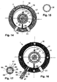
- the spring element 38 which is arranged between the rolling bearing 5 and the inside of the conveyor disc 6, designed as a spring coil element.
- the spring coil element 38 presses the conveyor disc 6 radially outwardly against the elastomer layer 18 on the outer ring 17, whereby tolerances of the shaft alignment and in the diameter of the conveyor disc and the outer ring can be compensated.
- the spring coil element 38 is preferably designed as a spring steel element. In an alternative embodiment come for the spring element 38 and rubber-elastic spring elements elastic plastic elements into consideration.
- valve member 46 In the embodiment according to the FIGS. 16 and 17 It has a pin-shaped valve member 46 and a valve ball 47, which is acted upon by the force of a spring element 85 in a closed position of the check valve 45.
- the im Check valve 45 slidably disposed valve member 46 protrudes into the delivery chamber 16 and is pressed by the conveyor disc 6 in the illustrated position of the conveyor disc at bottom dead center against the force of the spring member 85 radially outward.
- the valve ball 47 is lifted from the valve seat 86 and thus the check valve 45 is opened. In this open position, a small amount of fluid can flow back into the tank. This return flow takes place by reversing the direction of rotation of the eccentric shaft 3. In this case, the pressure side is specifically emptied.
- the purpose of the check valve 45 is to safely store the injected pressure on the pressure side without leakage via the pump. To protect the pressure side after switching off the vehicle or the eccentric pump 1 from the freezing of the medium, it is pumped out. To ensure this "backward pumping", the check valve 45 must be mechanically opened in the manner described. To ensure the tightness of the eccentric shaft 3 is stopped with the locking devices described in the zero position, so that the check valve 45 is closed.
- the check valve 45 is opened by the pressure of the fluid in the crescent-shaped delivery chamber 16 and the valve member 46, so that the fluid in the delivery chamber 16 via the open check valve 45 can flow out of the outlet port 32.
- the valve member 46 has a square base cross section with rounded corners, while a receptacle 87 in the check valve 45 has a circular cross-section.
- 45 flow channels 88 are formed in the check valve, through which the fluid flows in the direction of the valve ball 47.
- the spring element is designed so that the pressurized fluid lifts the valve ball 47 from the valve seat 86.
- a conveyor device with a combination of an eccentric pump 1 and an air pump 48 is shown, which is identical to the eccentric pump 1 is constructed.
- the eccentric pump 1 has a training in the embodiment Fig. 1 , She can also do an education accordingly have the further embodiments.
- the air pump 48 serves to additionally supply air during an injection process, for example, an aqueous urea solution in the exhaust line of a diesel internal combustion engine.
- the eccentric pump 1 and the air pump 48 are arranged axially directly one behind the other.
- Your pump housing 8 are adjacent to each other and are releasably connected by screws or the like.
- the eccentric shafts 3 are aligned with each other and are rotatably connected to each other by a coupling 49. It lies in passage openings 89, 90 in the adjacent housing walls 14 and 13 of the two pump housing eighth
- the conveyor forms a tandem pump with which the urea solution and air are simultaneously pumped.
- the air is sucked in via the suction connection of the air pump 48 and conveyed by means of the delivery chamber to the pressure connection.
- additional pumps can be mounted in the same way.
- FIGS. 19 and 20 a conveyor with eccentric pump 1 and air pump 48 is shown, which are arranged axially one behind the other as in the previous embodiment.
- the eccentric shafts 3 of the pumps 1 and 48 are rotatably connected to each other via the clutch 49.
- the air pump 48 is in this embodiment, however, not designed as an eccentric pump, but as a spiral pump and has a conveyor member on one side cantilevered spiral element 50. It is formed in two parts with an inner and an outer spiral member 91, 92, one of which is in a fixed position and the other of the eccentric shaft
- the radius decreasing inwards and concomitantly the reduction of the volume chamber 93 causes a compression of the air, which is sucked in via a suction opening 94.
- the disk 95 extends axially through a disk 95 and the housing wall 14 of the spiral pump 48.
- the disk 95 is positively connected to the housing wall 14 in the radial direction.
- the spiral 50 is located between the disc 95 and another disc 96, which is the same as the disc 95 is formed and arranged mirror-symmetrically to her.
- the eccentric shaft 3 of the air pump 48 passes through the disc 96 and extends to the spiral element 50. Coaxially to the eccentric shaft 3 is a bore 97 which forms a pressure connection and the disc 95 and the housing wall 14 passes through. The air sucked in via the intake opening 94 is conveyed by the spiral element 50 to the pressure port 97.
- the spiral 50 is surrounded by the outer ring 17, which is of the same design as the outer ring 17 of the eccentric pump 1. Since the spiral members 91, 92 roll on each other, no appreciable wear, so that the spiral pump works without lubrication.
- the spiral pump generates a sufficiently high air pressure of for example 1 bar to 2 bar, which is sufficient in combination with the urea injection via the eccentric pump 1.
- a propeller with a radial or axial fan can also be used as the air pump. If higher pressures are required, a positive displacement or piston machine may also be used.
Landscapes
- Engineering & Computer Science (AREA)
- Mechanical Engineering (AREA)
- General Engineering & Computer Science (AREA)
- Rotary Pumps (AREA)
- Details Of Reciprocating Pumps (AREA)
- Details And Applications Of Rotary Liquid Pumps (AREA)
Applications Claiming Priority (1)
| Application Number | Priority Date | Filing Date | Title |
|---|---|---|---|
| DE102015010997.9A DE102015010997B4 (de) | 2015-08-21 | 2015-08-21 | Exzenterpumpe, insbesondere Förderpumpe für wässrige Harnstofflösungen, und Fördervorrichtung mit einer Exzenterpumpe |
Publications (2)
| Publication Number | Publication Date |
|---|---|
| EP3141697A2 true EP3141697A2 (fr) | 2017-03-15 |
| EP3141697A3 EP3141697A3 (fr) | 2017-05-31 |
Family
ID=56787191
Family Applications (1)
| Application Number | Title | Priority Date | Filing Date |
|---|---|---|---|
| EP16001790.1A Withdrawn EP3141697A3 (fr) | 2015-08-21 | 2016-08-13 | Pompe excentrique, en particulier pompe d'alimentation pour solutions aqueuses d'uree et dispositif d'alimentation comprenant une pompe excentrique |
Country Status (2)
| Country | Link |
|---|---|
| EP (1) | EP3141697A3 (fr) |
| DE (1) | DE102015010997B4 (fr) |
Cited By (1)
| Publication number | Priority date | Publication date | Assignee | Title |
|---|---|---|---|---|
| DE102023115053A1 (de) * | 2023-06-07 | 2024-12-12 | B.Braun Avitum Ag | Schlauchrollenpumpe |
Families Citing this family (1)
| Publication number | Priority date | Publication date | Assignee | Title |
|---|---|---|---|---|
| DE102024104127A1 (de) * | 2024-02-14 | 2025-08-14 | Tesona Gmbh & Co. Kg | Förder- und Dosierpumpe zum Fördern einer einfrierfähigen Flüssigkeit |
Citations (1)
| Publication number | Priority date | Publication date | Assignee | Title |
|---|---|---|---|---|
| DE102011076976A1 (de) | 2011-06-06 | 2012-12-06 | Continental Automotive Gmbh | Hochdruckpumpe |
Family Cites Families (8)
| Publication number | Priority date | Publication date | Assignee | Title |
|---|---|---|---|---|
| DE2054033A1 (en) * | 1970-11-03 | 1972-05-04 | Brey, Helmut, Dipl.-Ing., 8940 Memmingen | Multicell compressor - with ptfe check plate |
| JPS5514783Y2 (fr) * | 1975-05-01 | 1980-04-04 | ||
| DE2751384A1 (de) * | 1977-11-17 | 1979-05-23 | Popp Hans Peter Dipl Ing | Exzenterpumpe |
| DE10024884A1 (de) * | 2000-05-19 | 2001-11-22 | Bosch Gmbh Robert | Zahnradförderpumpe |
| DE10040692C1 (de) * | 2000-08-19 | 2001-09-20 | Bosch Gmbh Robert | Innenzahnradpumpe |
| DE102009045574A1 (de) * | 2009-10-12 | 2011-04-14 | Robert Bosch Gmbh | Doppel-Innenzahnradpumpe |
| DE102011075415A1 (de) * | 2011-05-06 | 2012-11-08 | Robert Bosch Gmbh | Zahnpumpe |
| DE102011077949A1 (de) * | 2011-06-22 | 2012-12-27 | Robert Bosch Gmbh | Zahnradpumpe |
-
2015
- 2015-08-21 DE DE102015010997.9A patent/DE102015010997B4/de active Active
-
2016
- 2016-08-13 EP EP16001790.1A patent/EP3141697A3/fr not_active Withdrawn
Patent Citations (1)
| Publication number | Priority date | Publication date | Assignee | Title |
|---|---|---|---|---|
| DE102011076976A1 (de) | 2011-06-06 | 2012-12-06 | Continental Automotive Gmbh | Hochdruckpumpe |
Cited By (1)
| Publication number | Priority date | Publication date | Assignee | Title |
|---|---|---|---|---|
| DE102023115053A1 (de) * | 2023-06-07 | 2024-12-12 | B.Braun Avitum Ag | Schlauchrollenpumpe |
Also Published As
| Publication number | Publication date |
|---|---|
| DE102015010997A1 (de) | 2017-03-09 |
| EP3141697A3 (fr) | 2017-05-31 |
| DE102015010997B4 (de) | 2025-07-03 |
Similar Documents
| Publication | Publication Date | Title |
|---|---|---|
| EP1553291B1 (fr) | Machine a piston elevateur | |
| DE10229123A1 (de) | Spiralkompressor | |
| EP3081810B1 (fr) | Pompe pour un systeme scr de vehicules automobiles | |
| DE102012204264A1 (de) | Hochdruckpumpe | |
| WO1998058172A1 (fr) | Pompe a pistons radiaux | |
| EP3108137B1 (fr) | Pompe à carburant à piston pour moteur à combustion interne | |
| DE102015106610A1 (de) | Pumpenvorrichtung | |
| EP2612030B1 (fr) | Pompe à piston pour refouler des fluides et système de freinage pour véhicule associé | |
| EP3532728B1 (fr) | Pompe à piston rotatif munie d'une garniture d'étanchéité à chambre de barrage | |
| EP2143935B1 (fr) | Unité de pompe destinée à l'écoulement d'un fluide | |
| DE102008010286A1 (de) | Kolbenpumpe | |
| EP2909478B1 (fr) | Ensemble de soupape pour dispositif de transport | |
| DE102015010997B4 (de) | Exzenterpumpe, insbesondere Förderpumpe für wässrige Harnstofflösungen, und Fördervorrichtung mit einer Exzenterpumpe | |
| DE202015103751U1 (de) | Pumpenvorrichtung | |
| DE3631408A1 (de) | Axialkolbenpumpe | |
| DE3605452C2 (fr) | ||
| DE19725564C2 (de) | Radialkolbenpumpe | |
| WO2016173801A1 (fr) | Dispositif pompe | |
| EP2875239A1 (fr) | Ensemble poussoir | |
| DE102013205263A1 (de) | Hydrostatische Axialkolbenmaschine in Schrägscheibenbauart | |
| EP0985093B1 (fr) | Pompe a pistons radiaux | |
| DE102012212153A1 (de) | Hochdruckpumpe | |
| DE102019210653A1 (de) | Ventilvorrichtung für ein Kraftstoffversorgungssystem einer Brennkraftmaschine | |
| DE102012201308A1 (de) | Hochdruckpumpe | |
| WO2012136398A2 (fr) | Pompe à engrenages à denture intérieure |
Legal Events
| Date | Code | Title | Description |
|---|---|---|---|
| PUAI | Public reference made under article 153(3) epc to a published international application that has entered the european phase |
Free format text: ORIGINAL CODE: 0009012 |
|
| STAA | Information on the status of an ep patent application or granted ep patent |
Free format text: STATUS: THE APPLICATION HAS BEEN PUBLISHED |
|
| AK | Designated contracting states |
Kind code of ref document: A2 Designated state(s): AL AT BE BG CH CY CZ DE DK EE ES FI FR GB GR HR HU IE IS IT LI LT LU LV MC MK MT NL NO PL PT RO RS SE SI SK SM TR |
|
| AX | Request for extension of the european patent |
Extension state: BA ME |
|
| PUAL | Search report despatched |
Free format text: ORIGINAL CODE: 0009013 |
|
| AK | Designated contracting states |
Kind code of ref document: A3 Designated state(s): AL AT BE BG CH CY CZ DE DK EE ES FI FR GB GR HR HU IE IS IT LI LT LU LV MC MK MT NL NO PL PT RO RS SE SI SK SM TR |
|
| AX | Request for extension of the european patent |
Extension state: BA ME |
|
| RIC1 | Information provided on ipc code assigned before grant |
Ipc: F04C 14/28 20060101ALI20170427BHEP Ipc: F04C 5/00 20060101ALI20170427BHEP Ipc: F04C 15/00 20060101ALI20170427BHEP Ipc: F01C 21/10 20060101AFI20170427BHEP Ipc: F04C 2/356 20060101ALI20170427BHEP |
|
| STAA | Information on the status of an ep patent application or granted ep patent |
Free format text: STATUS: REQUEST FOR EXAMINATION WAS MADE |
|
| 17P | Request for examination filed |
Effective date: 20171130 |
|
| RBV | Designated contracting states (corrected) |
Designated state(s): AL AT BE BG CH CY CZ DE DK EE ES FI FR GB GR HR HU IE IS IT LI LT LU LV MC MK MT NL NO PL PT RO RS SE SI SK SM TR |
|
| STAA | Information on the status of an ep patent application or granted ep patent |
Free format text: STATUS: EXAMINATION IS IN PROGRESS |
|
| 17Q | First examination report despatched |
Effective date: 20210430 |
|
| STAA | Information on the status of an ep patent application or granted ep patent |
Free format text: STATUS: THE APPLICATION IS DEEMED TO BE WITHDRAWN |
|
| 18D | Application deemed to be withdrawn |
Effective date: 20210911 |