EP3141732A1 - Bläsertriebwerkmontiertes vorkühlersystem - Google Patents
Bläsertriebwerkmontiertes vorkühlersystem Download PDFInfo
- Publication number
- EP3141732A1 EP3141732A1 EP16187115.7A EP16187115A EP3141732A1 EP 3141732 A1 EP3141732 A1 EP 3141732A1 EP 16187115 A EP16187115 A EP 16187115A EP 3141732 A1 EP3141732 A1 EP 3141732A1
- Authority
- EP
- European Patent Office
- Prior art keywords
- air
- bypass
- precooler
- flow passage
- engine
- Prior art date
- Legal status (The legal status is an assumption and is not a legal conclusion. Google has not performed a legal analysis and makes no representation as to the accuracy of the status listed.)
- Withdrawn
Links
- 239000003570 air Substances 0.000 claims description 151
- 238000004891 communication Methods 0.000 claims description 14
- 230000000903 blocking effect Effects 0.000 claims description 13
- 239000012080 ambient air Substances 0.000 claims description 12
- 230000001105 regulatory effect Effects 0.000 claims description 7
- 238000007789 sealing Methods 0.000 claims description 2
- 238000001816 cooling Methods 0.000 description 4
- 238000002485 combustion reaction Methods 0.000 description 3
- 230000005465 channeling Effects 0.000 description 2
- 230000007613 environmental effect Effects 0.000 description 2
- 239000012530 fluid Substances 0.000 description 2
- 230000006870 function Effects 0.000 description 2
- 238000009434 installation Methods 0.000 description 2
- 238000004378 air conditioning Methods 0.000 description 1
- 239000000446 fuel Substances 0.000 description 1
- 239000000463 material Substances 0.000 description 1
- 238000000034 method Methods 0.000 description 1
- 239000000203 mixture Substances 0.000 description 1
- 230000002123 temporal effect Effects 0.000 description 1
- 230000000007 visual effect Effects 0.000 description 1
Images



Classifications
-
- F—MECHANICAL ENGINEERING; LIGHTING; HEATING; WEAPONS; BLASTING
- F02—COMBUSTION ENGINES; HOT-GAS OR COMBUSTION-PRODUCT ENGINE PLANTS
- F02K—JET-PROPULSION PLANTS
- F02K3/00—Plants including a gas turbine driving a compressor or a ducted fan
- F02K3/08—Plants including a gas turbine driving a compressor or a ducted fan with supplementary heating of the working fluid; Control thereof
- F02K3/105—Heating the by-pass flow
- F02K3/115—Heating the by-pass flow by means of indirect heat exchange
-
- F—MECHANICAL ENGINEERING; LIGHTING; HEATING; WEAPONS; BLASTING
- F02—COMBUSTION ENGINES; HOT-GAS OR COMBUSTION-PRODUCT ENGINE PLANTS
- F02C—GAS-TURBINE PLANTS; AIR INTAKES FOR JET-PROPULSION PLANTS; CONTROLLING FUEL SUPPLY IN AIR-BREATHING JET-PROPULSION PLANTS
- F02C7/00—Features, components parts, details or accessories, not provided for in, or of interest apart form groups F02C1/00 - F02C6/00; Air intakes for jet-propulsion plants
- F02C7/12—Cooling of plants
- F02C7/16—Cooling of plants characterised by cooling medium
- F02C7/18—Cooling of plants characterised by cooling medium the medium being gaseous, e.g. air
- F02C7/185—Cooling means for reducing the temperature of the cooling air or gas
-
- F—MECHANICAL ENGINEERING; LIGHTING; HEATING; WEAPONS; BLASTING
- F02—COMBUSTION ENGINES; HOT-GAS OR COMBUSTION-PRODUCT ENGINE PLANTS
- F02C—GAS-TURBINE PLANTS; AIR INTAKES FOR JET-PROPULSION PLANTS; CONTROLLING FUEL SUPPLY IN AIR-BREATHING JET-PROPULSION PLANTS
- F02C6/00—Plural gas-turbine plants; Combinations of gas-turbine plants with other apparatus; Adaptations of gas-turbine plants for special use
- F02C6/04—Gas-turbine plants providing heated or pressurised working fluid for other apparatus, e.g. without mechanical power output
- F02C6/06—Gas-turbine plants providing heated or pressurised working fluid for other apparatus, e.g. without mechanical power output providing compressed gas
- F02C6/08—Gas-turbine plants providing heated or pressurised working fluid for other apparatus, e.g. without mechanical power output providing compressed gas the gas being bled from the gas-turbine compressor
-
- F—MECHANICAL ENGINEERING; LIGHTING; HEATING; WEAPONS; BLASTING
- F02—COMBUSTION ENGINES; HOT-GAS OR COMBUSTION-PRODUCT ENGINE PLANTS
- F02C—GAS-TURBINE PLANTS; AIR INTAKES FOR JET-PROPULSION PLANTS; CONTROLLING FUEL SUPPLY IN AIR-BREATHING JET-PROPULSION PLANTS
- F02C7/00—Features, components parts, details or accessories, not provided for in, or of interest apart form groups F02C1/00 - F02C6/00; Air intakes for jet-propulsion plants
- F02C7/12—Cooling of plants
- F02C7/16—Cooling of plants characterised by cooling medium
- F02C7/18—Cooling of plants characterised by cooling medium the medium being gaseous, e.g. air
-
- Y—GENERAL TAGGING OF NEW TECHNOLOGICAL DEVELOPMENTS; GENERAL TAGGING OF CROSS-SECTIONAL TECHNOLOGIES SPANNING OVER SEVERAL SECTIONS OF THE IPC; TECHNICAL SUBJECTS COVERED BY FORMER USPC CROSS-REFERENCE ART COLLECTIONS [XRACs] AND DIGESTS
- Y02—TECHNOLOGIES OR APPLICATIONS FOR MITIGATION OR ADAPTATION AGAINST CLIMATE CHANGE
- Y02T—CLIMATE CHANGE MITIGATION TECHNOLOGIES RELATED TO TRANSPORTATION
- Y02T50/00—Aeronautics or air transport
- Y02T50/60—Efficient propulsion technologies, e.g. for aircraft
Definitions
- the present invention relates to a precooler system for use with a turbofan engine, and more particularly to a turbofan engine mounted precooler system.
- Turbofan engines are often configured to divert a portion of high-energy compressed air (generally from a compressor section of the turbofan engine) for use in other aircraft systems.
- the diverted compressed engine air may be supplied to aircraft systems, such as an aircraft environmental control system (ECS), an aircraft anti-ice system, and the like.
- ECS aircraft environmental control system
- the high temperature compressor bleed air is cooled by lower temperature fan bleed air.
- the diverted air is typically cooled by a precooler or heat exchanger (referred to herein as a precooler) prior to its introduction to the fuselage in aircraft with fuselage mounted engines.
- a precooler precooler or heat exchanger
- Locating a precooler proximate a turbofan engine is desirable but traditionally untenable.
- Turbofan engines are generally surrounded by a nacelle that provides a smooth outer cover, and creates a bounded space within which the turbofan engine operates.
- the space between the turbofan engine and the nacelle is limited and generally consumed by other turbofan engine systems. Consequently, in all but the largest of turbofan engines, space and weight considerations often drive the disposition of the precooler to locations remote from the turbofan engine, such as within the pylon. Additional ducting and components may then then be required for routing the engine air to and from the precooler.
- the additional ducting and components may add weight and cost to the aircraft, a generally undesirable result as the demand for more economical aircraft continues to increase.
- disposing of the precooler in the pylon requires the precooler system to have separate right hand and left hand permutations, and prohibits that pylon space to be used for other aircraft systems and devices.
- the separate left hand and right hand precooler system increases part count, and part cost.
- a non-handed precooler system having a symmetric precooler core that is optimized to be integrally mounted to the turbofan engine, regardless of the turbofan engine size.
- the desired precooler system optimizes available space between a turbofan engine and the nacelle, and does not substantially increase weight and cost.
- the present invention provides these features.
- a precooler system comprising:
- the precooler system comprising:
- a symmetrical precooler core comprising:
- the traditional turbofan engine comprises multiple sections, in stages.
- a simplified description of a traditional turbofan engine with a cooling system is provided as follows.
- a traditional turbofan engine is generally enclosed within a nacelle and comprises a fan section, a compressor section, a combustion section, a turbine section, and an exhaust section.
- the compressor section raises the pressure and increases the temperature of the air directed into it from the fan section.
- the compressor section may direct the compressed air into the combustion section.
- the combustion section the high pressure air is mixed with fuel and combusted.
- the combusted air is then directed into the turbine section, wherein it expands through turbines, causing them to rotate, and is then exhausted through a mixer nozzle and combines with air from a bypass duct.
- At least some compressed air is generally reserved for the aircraft. This is known as customer bleed air. It is generally high pressure and high temperature air that comes from the engine and is sent via ducting to the airframe.
- a cooling system typically includes a precooler. Prior to being sent to the precooler, the high pressure compressor discharge air is generally pressure regulated via several valves and associated ducting. Two of these valves include the high pressure shut off valve (HPSOV) and the pressure regulating shut off valve (PRSOV).
- HPSOV high pressure shut off valve
- PRSOV pressure regulating shut off valve
- the HPSOV selects the compressor stage from which the high pressure air source is retrieved.
- the PRSOV is generally used to control or modulate the quantity of engine air pressure flow in the ducting being supplied to other aircraft systems.
- FIG. 1 is a simplified illustration of a traditional precooler system for a turbofan engine and FIGs. 2-11 present a novel precooler core for a turbofan engine mounted precooler system.
- the precooler receives low pressure, low temperature fan discharge air from the engine. This air is used to cool the high pressure, high temperature compressor discharge air to be delivered to other aircraft subsystems located in the fuselage of the aircraft. After passing through the precooler, the low pressure air is discharged overboard. However, the fan discharge airflow is regulated by a fan air valve (FAV).
- the fan air valve is a modulating flow control system used to minimize the amount of fan air discharged overboard.
- Figure 1 shows the location of the fan air valve in a traditional precooler system.
- FIG. 1 is a simplified, cross-sectional view of a nacelle 100 having an airflow inlet at the forward side 104 and an exhaust nozzle at the aft side 102.
- Turbofan engine centerline 105 is shown.
- Nacelle 100 has a portion 108 removed to reveal an enclosed turbofan engine 107.
- Ducting 110 couples the turbofan engine to a precooler 112.
- the precooler 112 typically does not fit within available space between the nacelle 100 and the turbofan engine 107, and is therefore generally placed within a pylon 106, outside of the nacelle 100.
- the fan air valve 148 is generally placed within the pylon, outside of the nacelle.
- FIG. 2 is a simplified plan view of a turbofan engine showing a precooler system, in accordance with an exemplary embodiment.
- the provided precooler system 206 optimizes space between the turbofan engine 107 and the nacelle 100.
- "Stage" 155 represents a volumetric space wherein the turbofan engine 107 has the smallest diameter. Accordingly, at stage 155, the volumetric space between the turbofan engine 107 and the nacelle 100 is the largest.
- HPSOV 150 and PRSOV 152 are located substantially within turbofan engine stage 155, thereby optimizing available space.
- Ducting 154 provides engine air to precooler system 206, and ducting 156 channels discharge air released from precooler system 206 to a target aircraft system (not shown).
- precooler system 206 depicted in FIG. 2 may be referred to as a left handed implementation.
- the novel precooler core proposed herein is non-handed, in that it may be implemented in either direction (for comparison, refer to FIGs. 10-11 ).
- the precooler system 206 provides a first flow passage 158 being in flow communication with pressure regulated engine air at an engine air inlet 302 and discharge air at an engine air outlet 304.
- the precooler system 206 also provides one or more second flow passages 312 having a bypass flow path inlet ( FIG. 3 , 260) and one or more bypass flow path outlets 314.
- the second flow passage 312 being in flow communication with bypass air ( FIG. 3 202) at the bypass flow path inlet and ambient air at the bypass flow path outlet.
- an engine air supply duct 154 supplies compressed, high temperature engine air to the precooler system 206.
- the engine air supply duct 154 and duct 156 may alternatively be any structure suitable for delivering air to the precooler system 206.
- the precooler core ( FIG. 4 305) of the precooler system 206 is configured to transfer heat between a first fluid flowing through the first flow passage 158 and a second fluid flowing through the second flow passage 312.
- Cool or cold bypass air ( FIG. 3 202) from the bypass duct ( FIG. 3 214) enters the precooler core ( FIG. 4 305) at the bypass flow path inlet ( FIG. 3 260) and hot engine air enters the precooler core ( FIG. 4 305) at the engine air inlet 302.
- the cold and hot air are separately maintained in their respective flow paths by features within the precooler system 206.
- the precooler system 206 employs features such as cross tubes and deflector slats to promote exchange of heat from the hot turbofan engine air with the relatively cold bypass air ( FIG. 3 202) (cross tubes and deflector slats are described in connection with FIGs. 5-7 ).
- the cooled turbofan engine air is released as discharge air at the engine air outlet 304 and may then be delivered to a target aircraft system, such as an air conditioning system, ECS (Environmental Control System) package, or an aircraft cabin.
- ECS Endvironmental Control System
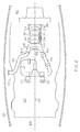
- FIG. 3 is a partial cross sectional view, above a turbofan engine centerline 105, of a turbofan engine 107 within nacelle 100, showing key features of a precooler system 206 in accordance with the exemplary embodiment.
- Bypass air 202 is shown flowing within bypass duct 214.
- Bypass duct 214 is bounded on one side by an inner surface 210 of nacelle 100 (defining an outer wall of the bypass duct 214) and on another side by an outer surface 212 of the turbofan engine 107, and extends axially through the nacelle 100.
- the inner surface 210 of the nacelle 100 is typically machined or manufactured to be smooth, free of blisters, pits, seams, or edges, machined to be a substantially continuous circumferential surface to minimize air obstruction within.
- precooler system 206 is disposed outside of the bypass duct 214 and mounted in an opening 216 in the nacelle 100.
- Ambient air 204 moves from the forward side 104 toward the aft side 102.
- Air in the bypass duct 302 is at a higher pressure that the ambient air 204. This makes it possible for cooling flow to pass through the precooler releasing heated air from the second flow passage 312 into ambient air 204.
- air may flow directly between the bypass duct 214 and the precooler system 206, without requiring any additional ducting.
- the provided precooler system 206 design may coordinate with a HPSOV 150 and PRSOV 152 that are each located within the space between the turbofan engine 107 and the nacelle 100 (stage 155), further optimizing turbofan engine 107 space and weight.
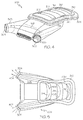
- FIG. 4 is three dimensional image showing key features of a precooler system 206, in accordance with the exemplary embodiment.
- the precooler system 206 comprises a precooler core 305, having a first flow passage 158 between an engine air inlet 302 and an engine air outlet 304, the first flow passage 158 configured to be in flow communication with engine air at the engine air inlet 302 and discharge air at the engine air outlet 304.
- the precooler core 305 has one or more second flow passages 312 having bypass flow path inlet (not shown) and a bypass flow path outlet 314, and configured to be in flow communication with bypass air 202 at the bypass flow path inlet and ambient air at the bypass flow path outlet 314.
- Bypass flow path outlets 314 allow bypass air ( FIG.
- the precooler system 206 is configured to transfer heat between the air flowing in the first flow passage 158 and the air flowing in the second flow passage 312 (openings 306 are described in connection with FIG. 6 ).
- the first flow passage is described in connection with FIG. 5 .
- the integrally mounted precooler system 206 When mounted to the nacelle 100, the integrally mounted precooler system 206 provides a smooth outer surface 316 that is substantially continuous with the outer surface of nacelle 100.
- precooler system 206 may comprise a plate 308, surrounded by a seal 310, the combination of which is configured to be integrally mounted into an appropriately sized opening 216 in nacelle 100, and forming a portion of the outer surface of the nacelle 100.
- the precooler core 305 has a surface sufficient to be integrally mounted into an appropriately sized opening 216 in the nacelle 100 and provide a smooth outer surface 316 that is substantially continuous with the outer surface of nacelle 100.
- FIG. 5 is an illustration of the precooler of FIG. 4 showing cross tubes 406 within the precooler core 305 of the precooler system 206.
- FIG. 5 is not to scale, but provides an intuitive visual depicting the cross tubes 406 extending through the first flow passage 158 and receiving hot engine air at the engine air inlet 302, channeling air through the precooler core, and releasing cooler discharge air at the engine air outlet 304.
- cooler bypass air 202 Concurrent with channeling hot engine air through the precooler core 305, cooler bypass air 202 is passing through one or more second flow passages 312, across one or more cross tubes 406 (by which it is being heated) in the second flow passages 312, and getting released into ambient air 204 outside of the nacelle 100.
- Bypass flow path outlets 314 provide a second flow passage 312 for the cooler bypass air 202 to cross the cross tubes 406 and cool the cross tubes 406 in doing so.
- cross tubes 406 their dimensions, and their composition are selected to maximize heat exchanging surface area as the movement of air in the second flow passages 312 travels across them, cooling the cross tubes 406 as it does so.
- the cross tubes 406 are stabilized within the precooler core 305 via a support structure. An exemplary support structure is described in connection with FIG. 6 .
- each additional cross tube 406 provides increased surface area for heat transfer.
- the cross tubes 406 have a diameter from about 1/8 of an inch to about 1 ⁇ 4 of an inch, and there are about ten cross tubes 406.
- FIG. 6 is a three dimensional image of a support structure 500, in accordance with an exemplary embodiment.
- Support structure 500 is configured to fit within the precooler core 305 and is coupled therein.
- the support structure 500 may be used to define positions and locations of features implemented to assist in heat exchange.
- support structure 500 may be used to define an arrangement of cross tubes such that each cross tube 406 in the arrangement of cross tubes extends from the engine air inlet 302 to the engine air outlet 304.
- support structure 500 comprises a first wall 505 and a second wall 507, each wall having a plurality of holes therethrough.
- the plurality of holes is arranged such that, when populated by cross tubes 406, the arrangement forms one or more air deflection paths to assist in heat exchange in the second flow passage 312.
- the plurality of holes is arranged in groups 504 of holes, each of the groups 504 forming a slight arc in the same direction.
- each group 504 of holes includes four holes; however, the number of holes in the plurality of holes and the number of holes in each group 504 is design specific.
- the support structure 500 may further comprise one or more deflector slats 502 coupled within the support structure 500 and oriented to deflect bypass air 202 and to assist in heat exchange through the second flow passage 312. Accordingly, in some embodiments, the support structure 500 may rely on an arrangement of the cross tubes 406 to deflect air, and in other embodiments, the support structure 500 may additionally rely on deflector slats 502 for deflecting air. Although the support structure 500 is shown as comprising a first wall 505 and a second wall 507, each wall having a plurality of holes therethrough, a variety of other configurations may be implemented to accomplish the same objective without straying from the scope of the invention.
- FIG. 7 is a partial cross sectional view of a precooler system 206 showing the support structure 500 of FIG. 6 coupled within, in accordance with the exemplary embodiment.
- FIG. 7 provides additional detail of the second flow passages 312, the bypass air 202 and the ambient air 204.
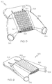
- FIG. 8 and FIG. 9 are three dimensional images showing a precooler with a blocking assembly on the bypass flow path inlet, in accordance with an exemplary embodiment.
- the blocking assembly is coupled to the bypass flow path inlet 260 and configured to (i) permit bypass air 202 to flow through the second flow passage 312 when the blocking assembly is in a first position, and (ii) prevent bypass air 202 from flowing through the second flow passage 312, thereby forming a substantially continuous outer wall of the bypass duct 214 when the blocking assembly is a second position.
- the louvers may be self-sealing and act as the fan air valve FAV, thus simplifying the system level design.
- louvers 802 are each attached to the precooler core 305 with moveable fasteners 804.
- the size, material and dimension of the louvers 802 and moveable fasteners 804 are application specific.
- the louvers 802 are shown in a first position (open), permitting bypass air 202 to flow through the second flow passage 312, and in FIG. 9 , louvers 802 are shown in a second position (closed), wherein the may self-seal and prevent bypass air 202 from flowing through the second flow passage 312, and form a substantially continuous outer wall of the bypass duct 214.
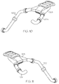
- FIG. 10 and FIG. 11 are three dimensional images showing the precooler core 305 utilized in a right handed and in a left handed precooler system 206 applications, respectively, in accordance with an exemplary embodiment.
- the precooler system 206 is "non-handed," in that it works in right handed and in left handed applications.
- the location of the HPSOV 150, PRSOV 152, and flow of engine air was depicted and described as occurring in first direction in first flow passage 158 in connection with FIGs. 2 , 4, and 5 , the direction of flow of engine air can be reversed through the precooler core 305 without redesign of the precooler core 305.
- implementing a left handed precooler core FIG.
- both implementations of the precooler system 206 work in coordination with the placement of the HPSOV 150 and PRSOV 152 at turbofan engine stage 155.
- a precooler system having a precooler core that is optimized to be integrally mounted to the turbofan engine, regardless of the turbofan engine size.
- the provided precooler system optimizes available space between a turbofan engine and the nacelle, and does not substantially increase weight and cost.
- the provided precooler system may be flexibly implemented as either a right handed precooler system or a left handed precooler system.
Landscapes
- Engineering & Computer Science (AREA)
- Chemical & Material Sciences (AREA)
- Combustion & Propulsion (AREA)
- Mechanical Engineering (AREA)
- General Engineering & Computer Science (AREA)
- Structures Of Non-Positive Displacement Pumps (AREA)
Applications Claiming Priority (1)
| Application Number | Priority Date | Filing Date | Title |
|---|---|---|---|
| US14/850,300 US20170074167A1 (en) | 2015-09-10 | 2015-09-10 | Turbofan engine mounted precooler system |
Publications (1)
| Publication Number | Publication Date |
|---|---|
| EP3141732A1 true EP3141732A1 (de) | 2017-03-15 |
Family
ID=56855350
Family Applications (1)
| Application Number | Title | Priority Date | Filing Date |
|---|---|---|---|
| EP16187115.7A Withdrawn EP3141732A1 (de) | 2015-09-10 | 2016-09-02 | Bläsertriebwerkmontiertes vorkühlersystem |
Country Status (2)
| Country | Link |
|---|---|
| US (1) | US20170074167A1 (de) |
| EP (1) | EP3141732A1 (de) |
Families Citing this family (2)
| Publication number | Priority date | Publication date | Assignee | Title |
|---|---|---|---|---|
| FR3007738B1 (fr) * | 2013-06-28 | 2015-07-31 | Aircelle Sa | Dispositif de degivrage et de conditionnement pour aeronef |
| CN110121463B (zh) * | 2016-06-30 | 2022-12-20 | 庞巴迪公司 | 用于在飞机上调节发动机加热的空气的组件和方法 |
Citations (5)
| Publication number | Priority date | Publication date | Assignee | Title |
|---|---|---|---|---|
| EP2492199A2 (de) * | 2011-02-28 | 2012-08-29 | General Electric Company | Vorkühlerversorgungsdurchführungsleitung für Umgebungskontrollsystem |
| US8266888B2 (en) * | 2010-06-24 | 2012-09-18 | Pratt & Whitney Canada Corp. | Cooler in nacelle with radial coolant |
| EP2711297A2 (de) * | 2012-09-21 | 2014-03-26 | The Boeing Company | Wärmetauschersysteme und Verfahren zur Steuerung einer Luftstromkühlung |
| FR2998050A1 (fr) * | 2012-11-09 | 2014-05-16 | Snecma | Procede et systeme de determination de debit d'air preleve sur un moteur |
| WO2015092251A1 (fr) * | 2013-12-19 | 2015-06-25 | Snecma | Turbomachine d'aéronef comportant un échangeur de chaleur du type pré-refroidisseur |
Family Cites Families (7)
| Publication number | Priority date | Publication date | Assignee | Title |
|---|---|---|---|---|
| US5161364A (en) * | 1991-04-01 | 1992-11-10 | United Technologies Corporation | Control of aircraft bleed air stage mixing |
| US7856824B2 (en) * | 2007-06-25 | 2010-12-28 | Honeywell International Inc. | Cooling systems for use on aircraft |
| US8910465B2 (en) * | 2009-12-31 | 2014-12-16 | Rolls-Royce North American Technologies, Inc. | Gas turbine engine and heat exchange system |
| US9109514B2 (en) * | 2012-01-10 | 2015-08-18 | Hamilton Sundstrand Corporation | Air recovery system for precooler heat-exchanger |
| US9243563B2 (en) * | 2012-01-25 | 2016-01-26 | Honeywell International Inc. | Gas turbine engine in-board cooled cooling air system |
| EP2904231B1 (de) * | 2012-10-01 | 2019-09-18 | United Technologies Corporation | Gasturbinenmotor mit zapfluftsystem mit zapfluftentnahmestellen vor und nach dem verdichter sowie entsprechendes verfahren |
| FR3019855B1 (fr) * | 2014-04-14 | 2016-04-01 | Airbus Operations Sas | Ensemble propulsif d'aeronef comprenant une vanne d'air a debit variable |
-
2015
- 2015-09-10 US US14/850,300 patent/US20170074167A1/en not_active Abandoned
-
2016
- 2016-09-02 EP EP16187115.7A patent/EP3141732A1/de not_active Withdrawn
Patent Citations (5)
| Publication number | Priority date | Publication date | Assignee | Title |
|---|---|---|---|---|
| US8266888B2 (en) * | 2010-06-24 | 2012-09-18 | Pratt & Whitney Canada Corp. | Cooler in nacelle with radial coolant |
| EP2492199A2 (de) * | 2011-02-28 | 2012-08-29 | General Electric Company | Vorkühlerversorgungsdurchführungsleitung für Umgebungskontrollsystem |
| EP2711297A2 (de) * | 2012-09-21 | 2014-03-26 | The Boeing Company | Wärmetauschersysteme und Verfahren zur Steuerung einer Luftstromkühlung |
| FR2998050A1 (fr) * | 2012-11-09 | 2014-05-16 | Snecma | Procede et systeme de determination de debit d'air preleve sur un moteur |
| WO2015092251A1 (fr) * | 2013-12-19 | 2015-06-25 | Snecma | Turbomachine d'aéronef comportant un échangeur de chaleur du type pré-refroidisseur |
Also Published As
| Publication number | Publication date |
|---|---|
| US20170074167A1 (en) | 2017-03-16 |
Similar Documents
| Publication | Publication Date | Title |
|---|---|---|
| EP2944767B1 (de) | Fluidsystem | |
| US10907546B2 (en) | Cross-stream heat exchanger | |
| EP2620618B1 (de) | Kühlluftsystem zum An-Bord-Kühlen eines Gasturbinenmotors | |
| US9267390B2 (en) | Bi-metallic actuator for selectively controlling air flow between plena in a gas turbine engine | |
| US9234707B2 (en) | Heat exchanger systems and methods for controlling airflow cooling | |
| CA2743279C (en) | Cooler in nacelle with radial coolant | |
| CN106988887B (zh) | 燃气涡轮发动机流体冷却系统及其组装方法 | |
| CA2626926C (en) | Cooling systems for use on aircraft | |
| US8516791B2 (en) | Methods and apparatus for mixing fluid in turbine engines | |
| GB2132279A (en) | Cooled exhaust nozzle flaps | |
| CA2491935A1 (en) | Cooling system for hot parts of an aircraft engine, and aircraft engine equipped with such a cooling system | |
| CN106882390B (zh) | 飞机引气预冷回热系统 | |
| EP2497908A2 (de) | Leitung für Luftabzweigung in einem Gasturbinenmotor | |
| US11408337B2 (en) | Aircraft pylon comprising a coaxial heat exchanger | |
| US10801406B2 (en) | Inlet bleed heat system for use in a turbine engine | |
| US7296397B2 (en) | Ventilation system for a convergent divergent exhaust nozzle | |
| EP3141732A1 (de) | Bläsertriebwerkmontiertes vorkühlersystem | |
| EP3048282A1 (de) | Gasturbinenmotor und blockiertüranordnung | |
| US20220290614A1 (en) | Aircraft having an engine and a cooling system | |
| US11046441B2 (en) | Adaptive plate-fin heat exchanger | |
| CA2626940A1 (en) | System and method for controlling processor usage according to user input | |
| RU2801984C1 (ru) | Система дефлекторов струй выброса воздуха теплообменника | |
| GB2555379A (en) | Gas turbine engine heat exchanger |
Legal Events
| Date | Code | Title | Description |
|---|---|---|---|
| PUAI | Public reference made under article 153(3) epc to a published international application that has entered the european phase |
Free format text: ORIGINAL CODE: 0009012 |
|
| STAA | Information on the status of an ep patent application or granted ep patent |
Free format text: STATUS: REQUEST FOR EXAMINATION WAS MADE |
|
| 17P | Request for examination filed |
Effective date: 20160902 |
|
| AK | Designated contracting states |
Kind code of ref document: A1 Designated state(s): AL AT BE BG CH CY CZ DE DK EE ES FI FR GB GR HR HU IE IS IT LI LT LU LV MC MK MT NL NO PL PT RO RS SE SI SK SM TR |
|
| AX | Request for extension of the european patent |
Extension state: BA ME |
|
| GRAP | Despatch of communication of intention to grant a patent |
Free format text: ORIGINAL CODE: EPIDOSNIGR1 |
|
| STAA | Information on the status of an ep patent application or granted ep patent |
Free format text: STATUS: GRANT OF PATENT IS INTENDED |
|
| INTG | Intention to grant announced |
Effective date: 20190305 |
|
| RIN1 | Information on inventor provided before grant (corrected) |
Inventor name: HOOVER, ROBERT Inventor name: ROMANO, ROBERT Inventor name: ANDERSON, MORRIS Inventor name: ALSTAD, SHAWN |
|
| STAA | Information on the status of an ep patent application or granted ep patent |
Free format text: STATUS: THE APPLICATION IS DEEMED TO BE WITHDRAWN |
|
| 18D | Application deemed to be withdrawn |
Effective date: 20190716 |
|
| P01 | Opt-out of the competence of the unified patent court (upc) registered |
Effective date: 20230525 |