EP3141739A1 - Installation hydraulique et son procédé de fonctionnement - Google Patents
Installation hydraulique et son procédé de fonctionnement Download PDFInfo
- Publication number
- EP3141739A1 EP3141739A1 EP15290230.0A EP15290230A EP3141739A1 EP 3141739 A1 EP3141739 A1 EP 3141739A1 EP 15290230 A EP15290230 A EP 15290230A EP 3141739 A1 EP3141739 A1 EP 3141739A1
- Authority
- EP
- European Patent Office
- Prior art keywords
- connecting element
- runner
- hydraulic
- hydraulic installation
- installation
- Prior art date
- Legal status (The legal status is an assumption and is not a legal conclusion. Google has not performed a legal analysis and makes no representation as to the accuracy of the status listed.)
- Granted
Links
Images



Classifications
-
- F—MECHANICAL ENGINEERING; LIGHTING; HEATING; WEAPONS; BLASTING
- F03—MACHINES OR ENGINES FOR LIQUIDS; WIND, SPRING, OR WEIGHT MOTORS; PRODUCING MECHANICAL POWER OR A REACTIVE PROPULSIVE THRUST, NOT OTHERWISE PROVIDED FOR
- F03B—MACHINES OR ENGINES FOR LIQUIDS
- F03B3/00—Machines or engines of reaction type; Parts or details peculiar thereto
- F03B3/10—Machines or engines of reaction type; Parts or details peculiar thereto characterised by having means for functioning alternatively as pumps or turbines
- F03B3/106—Machines or engines of reaction type; Parts or details peculiar thereto characterised by having means for functioning alternatively as pumps or turbines the turbine wheel and the pumps wheel being mounted in adjacent positions on the same shaft in a single casing
-
- F—MECHANICAL ENGINEERING; LIGHTING; HEATING; WEAPONS; BLASTING
- F03—MACHINES OR ENGINES FOR LIQUIDS; WIND, SPRING, OR WEIGHT MOTORS; PRODUCING MECHANICAL POWER OR A REACTIVE PROPULSIVE THRUST, NOT OTHERWISE PROVIDED FOR
- F03B—MACHINES OR ENGINES FOR LIQUIDS
- F03B11/00—Parts or details not provided for in, or of interest apart from, the preceding groups, e.g. wear-protection couplings, between turbine and generator
- F03B11/002—Injecting air or other fluid
-
- F—MECHANICAL ENGINEERING; LIGHTING; HEATING; WEAPONS; BLASTING
- F03—MACHINES OR ENGINES FOR LIQUIDS; WIND, SPRING, OR WEIGHT MOTORS; PRODUCING MECHANICAL POWER OR A REACTIVE PROPULSIVE THRUST, NOT OTHERWISE PROVIDED FOR
- F03B—MACHINES OR ENGINES FOR LIQUIDS
- F03B11/00—Parts or details not provided for in, or of interest apart from, the preceding groups, e.g. wear-protection couplings, between turbine and generator
- F03B11/02—Casings
-
- F—MECHANICAL ENGINEERING; LIGHTING; HEATING; WEAPONS; BLASTING
- F03—MACHINES OR ENGINES FOR LIQUIDS; WIND, SPRING, OR WEIGHT MOTORS; PRODUCING MECHANICAL POWER OR A REACTIVE PROPULSIVE THRUST, NOT OTHERWISE PROVIDED FOR
- F03B—MACHINES OR ENGINES FOR LIQUIDS
- F03B3/00—Machines or engines of reaction type; Parts or details peculiar thereto
- F03B3/02—Machines or engines of reaction type; Parts or details peculiar thereto with radial flow at high-pressure side and axial flow at low-pressure side of rotors, e.g. Francis turbines
-
- F—MECHANICAL ENGINEERING; LIGHTING; HEATING; WEAPONS; BLASTING
- F03—MACHINES OR ENGINES FOR LIQUIDS; WIND, SPRING, OR WEIGHT MOTORS; PRODUCING MECHANICAL POWER OR A REACTIVE PROPULSIVE THRUST, NOT OTHERWISE PROVIDED FOR
- F03B—MACHINES OR ENGINES FOR LIQUIDS
- F03B3/00—Machines or engines of reaction type; Parts or details peculiar thereto
- F03B3/16—Stators
- F03B3/18—Stator blades; Guide conduits or vanes, e.g. adjustable
- F03B3/183—Adjustable vanes, e.g. wicket gates
-
- F—MECHANICAL ENGINEERING; LIGHTING; HEATING; WEAPONS; BLASTING
- F05—INDEXING SCHEMES RELATING TO ENGINES OR PUMPS IN VARIOUS SUBCLASSES OF CLASSES F01-F04
- F05B—INDEXING SCHEME RELATING TO WIND, SPRING, WEIGHT, INERTIA OR LIKE MOTORS, TO MACHINES OR ENGINES FOR LIQUIDS COVERED BY SUBCLASSES F03B, F03D AND F03G
- F05B2270/00—Control
- F05B2270/30—Control parameters, e.g. input parameters
- F05B2270/301—Pressure
-
- Y—GENERAL TAGGING OF NEW TECHNOLOGICAL DEVELOPMENTS; GENERAL TAGGING OF CROSS-SECTIONAL TECHNOLOGIES SPANNING OVER SEVERAL SECTIONS OF THE IPC; TECHNICAL SUBJECTS COVERED BY FORMER USPC CROSS-REFERENCE ART COLLECTIONS [XRACs] AND DIGESTS
- Y02—TECHNOLOGIES OR APPLICATIONS FOR MITIGATION OR ADAPTATION AGAINST CLIMATE CHANGE
- Y02E—REDUCTION OF GREENHOUSE GAS [GHG] EMISSIONS, RELATED TO ENERGY GENERATION, TRANSMISSION OR DISTRIBUTION
- Y02E10/00—Energy generation through renewable energy sources
- Y02E10/20—Hydro energy
Definitions
- the present invention generally relates to hydraulic installations, such as hydraulic turbines. More specifically, the invention is directed to optimising power consumption when the turbine is used in condenser mode.
- a hydraulic installation comprising a hydraulic circuit which comprising a spiral casing which defines an annular passage including a plurality of wicket gates distributed there along; a runner chamber in fluid communication with the spiral casing and located downstream of the wicked gates; a runner rotatable in runner chamber; a draft tube arranged below the runner; a source of pressurised air in fluid communication with the draft tube; wherein the hydraulic installation further comprises a first connecting element fluidly connected to the spiral case and has an end discharging in atmosphere or, as an alternative to the first connecting element, it comprises a second connecting element fluidly connected to hydraulic circuit having an end discharging in the draft tube, wherein the second connecting element comprises a pump.
- the first connecting element intercepts the hydraulic circuit in correspondence of the spiral casing.
- the first connecting element intercepts the hydraulic circuit in correspondence of a gap of the runner chamber, the gap being located between the wicket gates and the runner.
- the second connecting element intercepts the hydraulic circuit in correspondence of the spiral casing.
- the second connecting element intercepts the hydraulic circuit in correspondence of a gap of the runner chamber, the gap being located between the wicket gates and the runner.
- the hydraulic installation comprises one or more pressure sensors arranged within the spiral case.
- the hydraulic installation comprises a first control unit configured to receive an input signal correspondent to a pressure value from the pressure sensors and elaborate an output control signal directed to the pump.
- the first connecting element comprises an opening/closure valve.
- the hydraulic installation comprises a second control unit configured to receive an input signal correspondent to a pressure value from the pressure sensors and elaborate an output control signal directed to the opening/closure valve.
- the wicket gates in the annular passage have an adjustable pitch such to be moved between an open position, allowing water passage to the runner, and a closed position where the water passage is interrupted.
- the hydraulic installation further comprises a third control unit configured to receive an input signal correspondent to a pressure value from the pressure sensors and elaborate an output control signal directed to adjust the pitch of the wicket gates.
- the first connecting element or the second connecting element intercepts the spiral casing at a summit thereof.
- the runner is located radially in the annular passage. It is a further object of the present invention to provide a method for retrofitting an existing hydraulic installation, wherein the hydraulic installation comprises a hydraulic circuit comprising a spiral casing which defines an annular passage including a plurality of wicket gates distributed there along; a runner chamber in fluid communication with the spiral casing and located downstream of the wicket gates; a runner rotatable in the runner chamber; a draft tube arranged below the runner; a source of pressurised air in fluid communication with the draft tube (5); wherein the method includes the step of providing a first connecting element fluidly connected to the hydraulic circuit, the first connecting element having an end discharging in atmosphere or, in alternative, includes the step of providing a second connecting element fluidly connected to the hydraulic circuit, the second connecting element comprising a pump.
- the method for retrofitting an existing hydraulic installation further includes the step of positioning an opening/closure valve along the first connecting element.
- the hydraulic installation comprising a hydraulic circuit which comprises a spiral casing which defines an annular passage including a plurality of wicket gates distributed there along, the wicket gates having an adjustable pitch; a runner chamber in fluid communication with the spiral casing and located downstream the wicket gates; a runner rotatable in the runner chamber; a draft tube arranged below the runner; a source of pressurised air in fluid communication with the draft tube; wherein the hydraulic installation comprises a first connecting element arranged between the spiral casing and having an end discharging in atmosphere, the second duct comprising an opening/closure valve; or, in alternative, a second connecting element arranged between the hydraulic circuit and the draft tube, the second connecting element comprising a pump; wherein the method includes the step of measuring the pressure inside the spiral casing and elaborate a
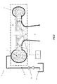
- Francis or reversible Francis turbine 100 comprises a hydraulic circuit, generally indicated in the figure with a dashed box having numeral reference 11, which comprises a spiral casing 2 which defines a spiral passage where the water flows, and a plurality of wicket gates 3 uniformly distributed there along.
- a runner 4 Radially located in the annular passage is a runner 4 which is put in rotation by the flow of water and located into a runner chamber 41.
- the wicket gates provided in the annular passage have an adjustable pitch such to be moved between an open position, allowing passage of water, and a closed position where the flow of water is interrupted.
- Runner 4 is in turn integral to a shaft 40 for the supply of electric power.
- a draft tube 5 is positioned below the runner, serving as a conduit which connects the exit of the runner to a tail race where the water is finally discharged.
- dewatering of runner 4 is achieved by positioning the wicket gates in a closed configuration, such not to allow the passage of water. Additionally, the draft tube 5 is dewatered with the aid of a source of pressurised air 7 in fluid communication with the draft tube.
- the pressure in the spiral case 2 may rise to levels which could cause an unwanted passage of water through the wicket gates.
- a duct 66 is arranged between the spiral case 2 and the draft tube 5, and intercepts the spiral casing 2 at a summit thereof.
- duct 66 water flows along a direction of a negative pressure gradient from the spiral case to the draft tube. This way the pressure in the spiral case 2 is reduced.
- the Francis turbine 1 differs from a known installation in that it comprises a first connecting element 8 fluidly connected to the hydraulic circuit, in particular to the spiral case 2, which has an end 81 discharging in the atmosphere.
- This first connecting element 8 with the exhaust at atmospheric pressure may be placed in addition or in alternative to the duct arranged between the spiral case and the draft tube (not shown) and it facilitates the process of reducing the pressure inside the spiral case 2.
- spiral case 2 may be provided with pressure sensors (not shown) arranged therein to monitor the pressure value during the condenser mode operational state.
- the first connecting element 8 may also be provided with an opening/closure valve 82 to control/adjust the discharge of water in atmosphere.
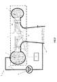
- the hydraulic installation 1 may comprise a second connecting element 6 arranged between the hydraulic circuit, and in particular the spiral case 2, and the draft tube 5.
- the second connecting element 6 comprises a pump 9 located along its path. This way, the flow of water from the spiral case 2 to the draft tube 5 is adjusted/regulated by means of the pump 9.
- the first connecting element 8 intercepts the hydraulic circuit in correspondence of a gap 411 located into the runner chamber 41, particularly between the wicket gates 3 and the runner 4.
- the second connecting element 6 intercepts the hydraulic circuit in correspondence of the gap 411 and has an end 61 discharging into the draft tube.
- the hydraulic installation comprises a first control unit 11, which is configured to receive an input signal correspondent to a pressure value from the pressure sensors 111 and elaborate an output control signal directed to the pump 9.
- the arrangement is such that the action of the pump to dewater the spiral case and thus reduce the pressure is regulated based on the pressure values measured in the spiral case during the condenser mode operation.
- hydraulic installation may comprise a second control unit 12 configured to receive an input signal correspondent to a pressure value from the pressure sensors 111 and elaborate an output control signal directed to the opening/closing valve 82.
- opening/closing valve 82 might have a mechanism such to allow partial closing/opening of the same, to further regulate the exhaust of water for dewatering the spiral case and hence gradually reducing its internal pressure.
- hydraulic installation may comprise a third control unit 13 configured to receive an input signal correspondent to a pressure value from the pressure sensors 111 and elaborate an output control signal directed to adjust the pitch of the wicket gates, which are indicated in the block with numeral reference 3. In this way, pressure inside the spiral case may also be regulated allowing the passage of the water flow into the runner.
- the method includes the step of connecting the first connecting element 8 to the hydraulic circuit, wherein the first connecting element has an end discharging in atmosphere.
- the first connecting element 8 may also be provided with an opening/closure valves 82 to further improve the process of dewatering the spiral case 2.
- the method may include the step of connecting a second connecting element 6 to the runner chamber, and in particular to the gap 411, located between the wicket gates and the runner, and providing a pump 9 along its path.
- the hydraulic installation comprises, with reference to figures 2-5 , a hydraulic circuit including a spiral casing 2 which defines an annular passage and a plurality of wicket gates distributed there along, wherein the wicked gates are provided with an adjustable pitch such to be moved between a totally open position, allowing water passage, and a closed position where the water passage is interrupted.
- the hydraulic installation further comprises a runner chamber in fluid communication with said spiral casing and located downstream of the wicket gates; a runner rotatable in the runner chamber; a draft tube arranged below the runner; a source of pressurised air in fluid communication with the draft tube 5; wherein the hydraulic installation comprises a first connecting element 6 arranged between the spiral casing 2 and having an end 81 discharging in atmosphere, the second duct 8 comprising an opening/closure valve 82; or a second connecting element 8 arranged between the hydraulic circuit 11 and the draft tube 5, the second connecting element 8 comprising a pump 9;
- the method for operating the hydraulic installation includes the step of measuring the pressure inside the spiral casing 2 and elaborating a control output signal, based on the pressure measurement, directed to adjust the pitch of the wicket gates or, in alternative, to control the opening/closure of the valve 82 or, in alternative, to regulate the pump 9.
Landscapes
- Engineering & Computer Science (AREA)
- Chemical & Material Sciences (AREA)
- Combustion & Propulsion (AREA)
- Mechanical Engineering (AREA)
- General Engineering & Computer Science (AREA)
- Hydraulic Turbines (AREA)
- Control Of Water Turbines (AREA)
- Control Of Turbines (AREA)
Priority Applications (6)
| Application Number | Priority Date | Filing Date | Title |
|---|---|---|---|
| EP15290230.0A EP3141739B2 (fr) | 2015-09-14 | 2015-09-14 | Installation hydraulique et son procédé de fonctionnement |
| PCT/EP2016/071315 WO2017046012A1 (fr) | 2015-09-14 | 2016-09-09 | Installation hydraulique et son procédé d'utilisation |
| BR112018004465-2A BR112018004465B1 (pt) | 2015-09-14 | 2016-09-09 | Instalação hidráulica, método para readaptação de uma instalação hidráulica e método para operação de uma instalação hidráulica |
| CN201680053294.1A CN108026891B (zh) | 2015-09-14 | 2016-09-09 | 水力设备和用于运行水力设备的方法 |
| CA2998441A CA2998441C (fr) | 2015-09-14 | 2016-09-09 | Installation hydraulique et son procede d'utilisation |
| US15/759,885 US10907608B2 (en) | 2015-09-14 | 2016-09-09 | Hydraulic installation and method for operating the same |
Applications Claiming Priority (1)
| Application Number | Priority Date | Filing Date | Title |
|---|---|---|---|
| EP15290230.0A EP3141739B2 (fr) | 2015-09-14 | 2015-09-14 | Installation hydraulique et son procédé de fonctionnement |
Publications (3)
| Publication Number | Publication Date |
|---|---|
| EP3141739A1 true EP3141739A1 (fr) | 2017-03-15 |
| EP3141739B1 EP3141739B1 (fr) | 2020-01-22 |
| EP3141739B2 EP3141739B2 (fr) | 2023-03-15 |
Family
ID=54291205
Family Applications (1)
| Application Number | Title | Priority Date | Filing Date |
|---|---|---|---|
| EP15290230.0A Active EP3141739B2 (fr) | 2015-09-14 | 2015-09-14 | Installation hydraulique et son procédé de fonctionnement |
Country Status (6)
| Country | Link |
|---|---|
| US (1) | US10907608B2 (fr) |
| EP (1) | EP3141739B2 (fr) |
| CN (1) | CN108026891B (fr) |
| BR (1) | BR112018004465B1 (fr) |
| CA (1) | CA2998441C (fr) |
| WO (1) | WO2017046012A1 (fr) |
Citations (5)
| Publication number | Priority date | Publication date | Assignee | Title |
|---|---|---|---|---|
| JPS557916A (en) * | 1978-06-30 | 1980-01-21 | Toshiba Corp | Hydraulic machinery |
| JPS57181974A (en) * | 1981-04-30 | 1982-11-09 | Toshiba Corp | Idle running device of water turbine or pump-turbine |
| JPS58106180A (ja) * | 1981-12-18 | 1983-06-24 | Mitsubishi Heavy Ind Ltd | ポンプ水車等の調相運転時の排水方法 |
| JPH11324888A (ja) * | 1998-05-08 | 1999-11-26 | Toshiba Corp | 水力機械及びその運転方法 |
| JP2001165024A (ja) * | 1999-12-14 | 2001-06-19 | Toshiba Corp | フランシス形水力機械 |
Family Cites Families (21)
| Publication number | Priority date | Publication date | Assignee | Title |
|---|---|---|---|---|
| US3174719A (en) * | 1962-06-12 | 1965-03-23 | Dominion Eng Works Ltd | Francis turbines and centrifugal pumps |
| GB1047014A (en) * | 1962-07-03 | 1966-11-02 | English Electric Co Ltd | Improvements in or relating to hydraulic pumps, turbines or reversible pump turbines |
| GB1060395A (en) * | 1962-10-02 | 1967-03-01 | Hitachi Ltd | Methods and apparatus for reducing water hammer in the tailrace or suction line of a water turbine, pump turbine, or pump |
| US3307828A (en) * | 1966-06-29 | 1967-03-07 | Baldwin Lima Hamilton Corp | Torque reducing means |
| US3658436A (en) † | 1969-03-10 | 1972-04-25 | Hitachi Ltd | Water turbine operation method and system |
| JPS4910206B1 (fr) | 1969-09-12 | 1974-03-08 | ||
| JPS5058441A (fr) * | 1973-09-26 | 1975-05-21 | ||
| JPS5146504A (ja) | 1974-10-21 | 1976-04-21 | Komatsu Mfg Co Ltd | Jibankutsusakusochi |
| JPS5346533A (en) * | 1976-10-08 | 1978-04-26 | Hitachi Ltd | Operating method of hydraulic machinery |
| JPS5372942A (en) † | 1976-12-10 | 1978-06-28 | Hitachi Ltd | Hydraulic machine operation |
| JPS5395447A (en) * | 1977-01-31 | 1978-08-21 | Toshiba Corp | Operation of reversible pump-turbine |
| JPS56107972A (en) | 1980-01-30 | 1981-08-27 | Toshiba Corp | Operation control device for hydraulic machinery |
| JPH0830462B2 (ja) | 1987-05-08 | 1996-03-27 | 株式会社東芝 | 可変速のポンプ水車またはポンプの揚水起動方法 |
| CA2549749C (fr) * | 2006-06-09 | 2015-05-19 | General Electric Company | Jet de commande pour turbine hydraulique |
| FR2923553A1 (fr) * | 2007-11-14 | 2009-05-15 | Alstom Power Hydraulique Sa | Installation hydraulique de conversion d'energie et procede de commande d'une telle installation |
| FR2942274B1 (fr) * | 2009-02-18 | 2014-04-18 | Alstom Hydro France | Installation hydraulique de conversion d'energie et procede de commande d'une telle installation |
| NO329647B1 (no) * | 2009-07-14 | 2010-11-22 | Dynavec As | Fremgangsmåte og anordning for å motvirke slitasje omkring en ledeskovl |
| NO20092682A (no) * | 2009-07-15 | 2010-11-22 | Dynavec As | Fremgangsmåte og anordning for å motvirke slitasje fra partikkelholdig drivvann i et løpehjul |
| JP5956885B2 (ja) * | 2012-09-19 | 2016-07-27 | 株式会社東芝 | 水力機械およびその運転方法 |
| WO2014147300A1 (fr) * | 2013-03-19 | 2014-09-25 | Alstom Renewable Technologies | Turbine hydraulique et installation de conversion d'energie comprenant une telle turbine |
| JP2016173075A (ja) * | 2015-03-17 | 2016-09-29 | 株式会社東芝 | 水力機械及びその運転方法 |
-
2015
- 2015-09-14 EP EP15290230.0A patent/EP3141739B2/fr active Active
-
2016
- 2016-09-09 CA CA2998441A patent/CA2998441C/fr active Active
- 2016-09-09 WO PCT/EP2016/071315 patent/WO2017046012A1/fr not_active Ceased
- 2016-09-09 US US15/759,885 patent/US10907608B2/en active Active
- 2016-09-09 BR BR112018004465-2A patent/BR112018004465B1/pt active IP Right Grant
- 2016-09-09 CN CN201680053294.1A patent/CN108026891B/zh active Active
Patent Citations (5)
| Publication number | Priority date | Publication date | Assignee | Title |
|---|---|---|---|---|
| JPS557916A (en) * | 1978-06-30 | 1980-01-21 | Toshiba Corp | Hydraulic machinery |
| JPS57181974A (en) * | 1981-04-30 | 1982-11-09 | Toshiba Corp | Idle running device of water turbine or pump-turbine |
| JPS58106180A (ja) * | 1981-12-18 | 1983-06-24 | Mitsubishi Heavy Ind Ltd | ポンプ水車等の調相運転時の排水方法 |
| JPH11324888A (ja) * | 1998-05-08 | 1999-11-26 | Toshiba Corp | 水力機械及びその運転方法 |
| JP2001165024A (ja) * | 1999-12-14 | 2001-06-19 | Toshiba Corp | フランシス形水力機械 |
Also Published As
| Publication number | Publication date |
|---|---|
| EP3141739B1 (fr) | 2020-01-22 |
| CA2998441C (fr) | 2023-10-17 |
| CN108026891B (zh) | 2020-11-03 |
| WO2017046012A1 (fr) | 2017-03-23 |
| BR112018004465B1 (pt) | 2023-01-10 |
| CA2998441A1 (fr) | 2017-03-23 |
| EP3141739B2 (fr) | 2023-03-15 |
| BR112018004465A2 (pt) | 2018-09-25 |
| CN108026891A (zh) | 2018-05-11 |
| US10907608B2 (en) | 2021-02-02 |
| US20180252198A1 (en) | 2018-09-06 |
Similar Documents
| Publication | Publication Date | Title |
|---|---|---|
| US20100290889A1 (en) | Turbine wheelspace temperature control | |
| CN101910618B (zh) | 能量转换用的液力设备以及这种设备的控制方法 | |
| US3658436A (en) | Water turbine operation method and system | |
| US20200040732A1 (en) | Steam turbine | |
| CN105143606B (zh) | 用于平衡推力的方法、涡轮和涡轮发动机 | |
| KR101666318B1 (ko) | 소수력 발전기능을 구비한 펌프 게이트 시스템 | |
| JP2014518349A (ja) | ポンプタービン設備 | |
| RU2658721C2 (ru) | Силовая машина с текучей средой с двойным сухим газовым уплотнением типа "тандем" | |
| EP3141739B1 (fr) | Installation hydraulique et son procédé de fonctionnement | |
| CN102878002B (zh) | 一种防止水轮机引水系统水击压力升高的方法 | |
| US10494947B2 (en) | Operation method for steam turbine, and steam turbine | |
| JP6884683B2 (ja) | 水力機械のスラスト制御システムおよび水力機械 | |
| CN106065877A (zh) | 一种离心压缩机无叶扩压器扩稳系统 | |
| US20130142618A1 (en) | Steam turbine arrangement of a three casing supercritical steam turbine | |
| CA3048394C (fr) | Centrale electrique ayant une turbine kaplan, un groupe bulbe, une turbine a ecoulement diagonal ou une turbine-helice | |
| JP7843254B2 (ja) | 水力機械およびその制御方法 | |
| JP4758797B2 (ja) | 水力発電用フランシス水車 | |
| JP6433269B2 (ja) | ポンプ逆転水車型発電装置 | |
| CN201705528U (zh) | 水轮发电机组防止抬机的装置 | |
| CN114239381A (zh) | 一种求解机组甩负荷时导叶关闭临界点模型的方法 | |
| JP2007120459A (ja) | 発電用水力機械のガイドベーン閉鎖制御装置およびその制御方法 | |
| CN111720253A (zh) | 用于处理浆料的方法及系统 | |
| JPWO2014199643A1 (ja) | エンジンシステム及び船舶 | |
| CN115681191B (zh) | 密封风机控制方法、装置、存储介质及电子设备 | |
| JP2010150943A (ja) | 水力発電システム |
Legal Events
| Date | Code | Title | Description |
|---|---|---|---|
| PUAI | Public reference made under article 153(3) epc to a published international application that has entered the european phase |
Free format text: ORIGINAL CODE: 0009012 |
|
| STAA | Information on the status of an ep patent application or granted ep patent |
Free format text: STATUS: THE APPLICATION HAS BEEN PUBLISHED |
|
| AK | Designated contracting states |
Kind code of ref document: A1 Designated state(s): AL AT BE BG CH CY CZ DE DK EE ES FI FR GB GR HR HU IE IS IT LI LT LU LV MC MK MT NL NO PL PT RO RS SE SI SK SM TR |
|
| AX | Request for extension of the european patent |
Extension state: BA ME |
|
| RAP1 | Party data changed (applicant data changed or rights of an application transferred) |
Owner name: GE RENEWABLE TECHNOLOGIES |
|
| STAA | Information on the status of an ep patent application or granted ep patent |
Free format text: STATUS: REQUEST FOR EXAMINATION WAS MADE |
|
| 17P | Request for examination filed |
Effective date: 20170915 |
|
| RBV | Designated contracting states (corrected) |
Designated state(s): AL AT BE BG CH CY CZ DE DK EE ES FI FR GB GR HR HU IE IS IT LI LT LU LV MC MK MT NL NO PL PT RO RS SE SI SK SM TR |
|
| STAA | Information on the status of an ep patent application or granted ep patent |
Free format text: STATUS: EXAMINATION IS IN PROGRESS |
|
| 17Q | First examination report despatched |
Effective date: 20180516 |
|
| GRAP | Despatch of communication of intention to grant a patent |
Free format text: ORIGINAL CODE: EPIDOSNIGR1 |
|
| STAA | Information on the status of an ep patent application or granted ep patent |
Free format text: STATUS: GRANT OF PATENT IS INTENDED |
|
| INTG | Intention to grant announced |
Effective date: 20190703 |
|
| GRAS | Grant fee paid |
Free format text: ORIGINAL CODE: EPIDOSNIGR3 |
|
| GRAJ | Information related to disapproval of communication of intention to grant by the applicant or resumption of examination proceedings by the epo deleted |
Free format text: ORIGINAL CODE: EPIDOSDIGR1 |
|
| GRAL | Information related to payment of fee for publishing/printing deleted |
Free format text: ORIGINAL CODE: EPIDOSDIGR3 |
|
| STAA | Information on the status of an ep patent application or granted ep patent |
Free format text: STATUS: EXAMINATION IS IN PROGRESS |
|
| GRAR | Information related to intention to grant a patent recorded |
Free format text: ORIGINAL CODE: EPIDOSNIGR71 |
|
| STAA | Information on the status of an ep patent application or granted ep patent |
Free format text: STATUS: GRANT OF PATENT IS INTENDED |
|
| INTC | Intention to grant announced (deleted) | ||
| GRAA | (expected) grant |
Free format text: ORIGINAL CODE: 0009210 |
|
| STAA | Information on the status of an ep patent application or granted ep patent |
Free format text: STATUS: THE PATENT HAS BEEN GRANTED |
|
| INTG | Intention to grant announced |
Effective date: 20191206 |
|
| AK | Designated contracting states |
Kind code of ref document: B1 Designated state(s): AL AT BE BG CH CY CZ DE DK EE ES FI FR GB GR HR HU IE IS IT LI LT LU LV MC MK MT NL NO PL PT RO RS SE SI SK SM TR |
|
| REG | Reference to a national code |
Ref country code: GB Ref legal event code: FG4D |
|
| REG | Reference to a national code |
Ref country code: CH Ref legal event code: EP |
|
| REG | Reference to a national code |
Ref country code: DE Ref legal event code: R096 Ref document number: 602015045940 Country of ref document: DE |
|
| REG | Reference to a national code |
Ref country code: AT Ref legal event code: REF Ref document number: 1227062 Country of ref document: AT Kind code of ref document: T Effective date: 20200215 |
|
| REG | Reference to a national code |
Ref country code: IE Ref legal event code: FG4D |
|
| REG | Reference to a national code |
Ref country code: NL Ref legal event code: MP Effective date: 20200122 |
|
| REG | Reference to a national code |
Ref country code: LT Ref legal event code: MG4D |
|
| PG25 | Lapsed in a contracting state [announced via postgrant information from national office to epo] |
Ref country code: NO Free format text: LAPSE BECAUSE OF FAILURE TO SUBMIT A TRANSLATION OF THE DESCRIPTION OR TO PAY THE FEE WITHIN THE PRESCRIBED TIME-LIMIT Effective date: 20200422 Ref country code: RS Free format text: LAPSE BECAUSE OF FAILURE TO SUBMIT A TRANSLATION OF THE DESCRIPTION OR TO PAY THE FEE WITHIN THE PRESCRIBED TIME-LIMIT Effective date: 20200122 Ref country code: FI Free format text: LAPSE BECAUSE OF FAILURE TO SUBMIT A TRANSLATION OF THE DESCRIPTION OR TO PAY THE FEE WITHIN THE PRESCRIBED TIME-LIMIT Effective date: 20200122 Ref country code: NL Free format text: LAPSE BECAUSE OF FAILURE TO SUBMIT A TRANSLATION OF THE DESCRIPTION OR TO PAY THE FEE WITHIN THE PRESCRIBED TIME-LIMIT Effective date: 20200122 Ref country code: PT Free format text: LAPSE BECAUSE OF FAILURE TO SUBMIT A TRANSLATION OF THE DESCRIPTION OR TO PAY THE FEE WITHIN THE PRESCRIBED TIME-LIMIT Effective date: 20200614 |
|
| PG25 | Lapsed in a contracting state [announced via postgrant information from national office to epo] |
Ref country code: LV Free format text: LAPSE BECAUSE OF FAILURE TO SUBMIT A TRANSLATION OF THE DESCRIPTION OR TO PAY THE FEE WITHIN THE PRESCRIBED TIME-LIMIT Effective date: 20200122 Ref country code: IS Free format text: LAPSE BECAUSE OF FAILURE TO SUBMIT A TRANSLATION OF THE DESCRIPTION OR TO PAY THE FEE WITHIN THE PRESCRIBED TIME-LIMIT Effective date: 20200522 Ref country code: SE Free format text: LAPSE BECAUSE OF FAILURE TO SUBMIT A TRANSLATION OF THE DESCRIPTION OR TO PAY THE FEE WITHIN THE PRESCRIBED TIME-LIMIT Effective date: 20200122 Ref country code: GR Free format text: LAPSE BECAUSE OF FAILURE TO SUBMIT A TRANSLATION OF THE DESCRIPTION OR TO PAY THE FEE WITHIN THE PRESCRIBED TIME-LIMIT Effective date: 20200423 Ref country code: HR Free format text: LAPSE BECAUSE OF FAILURE TO SUBMIT A TRANSLATION OF THE DESCRIPTION OR TO PAY THE FEE WITHIN THE PRESCRIBED TIME-LIMIT Effective date: 20200122 Ref country code: BG Free format text: LAPSE BECAUSE OF FAILURE TO SUBMIT A TRANSLATION OF THE DESCRIPTION OR TO PAY THE FEE WITHIN THE PRESCRIBED TIME-LIMIT Effective date: 20200422 |
|
| REG | Reference to a national code |
Ref country code: DE Ref legal event code: R026 Ref document number: 602015045940 Country of ref document: DE |
|
| PLBI | Opposition filed |
Free format text: ORIGINAL CODE: 0009260 |
|
| PG25 | Lapsed in a contracting state [announced via postgrant information from national office to epo] |
Ref country code: EE Free format text: LAPSE BECAUSE OF FAILURE TO SUBMIT A TRANSLATION OF THE DESCRIPTION OR TO PAY THE FEE WITHIN THE PRESCRIBED TIME-LIMIT Effective date: 20200122 Ref country code: ES Free format text: LAPSE BECAUSE OF FAILURE TO SUBMIT A TRANSLATION OF THE DESCRIPTION OR TO PAY THE FEE WITHIN THE PRESCRIBED TIME-LIMIT Effective date: 20200122 Ref country code: LT Free format text: LAPSE BECAUSE OF FAILURE TO SUBMIT A TRANSLATION OF THE DESCRIPTION OR TO PAY THE FEE WITHIN THE PRESCRIBED TIME-LIMIT Effective date: 20200122 Ref country code: CZ Free format text: LAPSE BECAUSE OF FAILURE TO SUBMIT A TRANSLATION OF THE DESCRIPTION OR TO PAY THE FEE WITHIN THE PRESCRIBED TIME-LIMIT Effective date: 20200122 Ref country code: RO Free format text: LAPSE BECAUSE OF FAILURE TO SUBMIT A TRANSLATION OF THE DESCRIPTION OR TO PAY THE FEE WITHIN THE PRESCRIBED TIME-LIMIT Effective date: 20200122 Ref country code: SK Free format text: LAPSE BECAUSE OF FAILURE TO SUBMIT A TRANSLATION OF THE DESCRIPTION OR TO PAY THE FEE WITHIN THE PRESCRIBED TIME-LIMIT Effective date: 20200122 Ref country code: SM Free format text: LAPSE BECAUSE OF FAILURE TO SUBMIT A TRANSLATION OF THE DESCRIPTION OR TO PAY THE FEE WITHIN THE PRESCRIBED TIME-LIMIT Effective date: 20200122 Ref country code: DK Free format text: LAPSE BECAUSE OF FAILURE TO SUBMIT A TRANSLATION OF THE DESCRIPTION OR TO PAY THE FEE WITHIN THE PRESCRIBED TIME-LIMIT Effective date: 20200122 |
|
| 26 | Opposition filed |
Opponent name: VOITH PATENT GMBH Effective date: 20201006 |
|
| PLAX | Notice of opposition and request to file observation + time limit sent |
Free format text: ORIGINAL CODE: EPIDOSNOBS2 |
|
| PG25 | Lapsed in a contracting state [announced via postgrant information from national office to epo] |
Ref country code: IT Free format text: LAPSE BECAUSE OF FAILURE TO SUBMIT A TRANSLATION OF THE DESCRIPTION OR TO PAY THE FEE WITHIN THE PRESCRIBED TIME-LIMIT Effective date: 20200122 |
|
| PG25 | Lapsed in a contracting state [announced via postgrant information from national office to epo] |
Ref country code: SI Free format text: LAPSE BECAUSE OF FAILURE TO SUBMIT A TRANSLATION OF THE DESCRIPTION OR TO PAY THE FEE WITHIN THE PRESCRIBED TIME-LIMIT Effective date: 20200122 Ref country code: PL Free format text: LAPSE BECAUSE OF FAILURE TO SUBMIT A TRANSLATION OF THE DESCRIPTION OR TO PAY THE FEE WITHIN THE PRESCRIBED TIME-LIMIT Effective date: 20200122 |
|
| PLBB | Reply of patent proprietor to notice(s) of opposition received |
Free format text: ORIGINAL CODE: EPIDOSNOBS3 |
|
| PG25 | Lapsed in a contracting state [announced via postgrant information from national office to epo] |
Ref country code: MC Free format text: LAPSE BECAUSE OF FAILURE TO SUBMIT A TRANSLATION OF THE DESCRIPTION OR TO PAY THE FEE WITHIN THE PRESCRIBED TIME-LIMIT Effective date: 20200122 |
|
| GBPC | Gb: european patent ceased through non-payment of renewal fee |
Effective date: 20200914 |
|
| REG | Reference to a national code |
Ref country code: BE Ref legal event code: MM Effective date: 20200930 |
|
| PG25 | Lapsed in a contracting state [announced via postgrant information from national office to epo] |
Ref country code: LU Free format text: LAPSE BECAUSE OF NON-PAYMENT OF DUE FEES Effective date: 20200914 |
|
| PG25 | Lapsed in a contracting state [announced via postgrant information from national office to epo] |
Ref country code: BE Free format text: LAPSE BECAUSE OF NON-PAYMENT OF DUE FEES Effective date: 20200930 Ref country code: GB Free format text: LAPSE BECAUSE OF NON-PAYMENT OF DUE FEES Effective date: 20200914 Ref country code: IE Free format text: LAPSE BECAUSE OF NON-PAYMENT OF DUE FEES Effective date: 20200914 |
|
| PG25 | Lapsed in a contracting state [announced via postgrant information from national office to epo] |
Ref country code: TR Free format text: LAPSE BECAUSE OF FAILURE TO SUBMIT A TRANSLATION OF THE DESCRIPTION OR TO PAY THE FEE WITHIN THE PRESCRIBED TIME-LIMIT Effective date: 20200122 Ref country code: MT Free format text: LAPSE BECAUSE OF FAILURE TO SUBMIT A TRANSLATION OF THE DESCRIPTION OR TO PAY THE FEE WITHIN THE PRESCRIBED TIME-LIMIT Effective date: 20200122 Ref country code: CY Free format text: LAPSE BECAUSE OF FAILURE TO SUBMIT A TRANSLATION OF THE DESCRIPTION OR TO PAY THE FEE WITHIN THE PRESCRIBED TIME-LIMIT Effective date: 20200122 |
|
| PG25 | Lapsed in a contracting state [announced via postgrant information from national office to epo] |
Ref country code: MK Free format text: LAPSE BECAUSE OF FAILURE TO SUBMIT A TRANSLATION OF THE DESCRIPTION OR TO PAY THE FEE WITHIN THE PRESCRIBED TIME-LIMIT Effective date: 20200122 Ref country code: AL Free format text: LAPSE BECAUSE OF FAILURE TO SUBMIT A TRANSLATION OF THE DESCRIPTION OR TO PAY THE FEE WITHIN THE PRESCRIBED TIME-LIMIT Effective date: 20200122 |
|
| APAH | Appeal reference modified |
Free format text: ORIGINAL CODE: EPIDOSCREFNO |
|
| APBM | Appeal reference recorded |
Free format text: ORIGINAL CODE: EPIDOSNREFNO |
|
| APBP | Date of receipt of notice of appeal recorded |
Free format text: ORIGINAL CODE: EPIDOSNNOA2O |
|
| APBU | Appeal procedure closed |
Free format text: ORIGINAL CODE: EPIDOSNNOA9O |
|
| REG | Reference to a national code |
Ref country code: AT Ref legal event code: UEP Ref document number: 1227062 Country of ref document: AT Kind code of ref document: T Effective date: 20200122 |
|
| PUAH | Patent maintained in amended form |
Free format text: ORIGINAL CODE: 0009272 |
|
| STAA | Information on the status of an ep patent application or granted ep patent |
Free format text: STATUS: PATENT MAINTAINED AS AMENDED |
|
| 27A | Patent maintained in amended form |
Effective date: 20230315 |
|
| AK | Designated contracting states |
Kind code of ref document: B2 Designated state(s): AL AT BE BG CH CY CZ DE DK EE ES FI FR GB GR HR HU IE IS IT LI LT LU LV MC MK MT NL NO PL PT RO RS SE SI SK SM TR |
|
| REG | Reference to a national code |
Ref country code: DE Ref legal event code: R102 Ref document number: 602015045940 Country of ref document: DE |
|
| P01 | Opt-out of the competence of the unified patent court (upc) registered |
Effective date: 20230522 |
|
| REG | Reference to a national code |
Ref country code: CH Ref legal event code: U11 Free format text: ST27 STATUS EVENT CODE: U-0-0-U10-U11 (AS PROVIDED BY THE NATIONAL OFFICE) Effective date: 20251001 |
|
| PGFP | Annual fee paid to national office [announced via postgrant information from national office to epo] |
Ref country code: DE Payment date: 20250820 Year of fee payment: 11 |
|
| PGFP | Annual fee paid to national office [announced via postgrant information from national office to epo] |
Ref country code: FR Payment date: 20250820 Year of fee payment: 11 Ref country code: AT Payment date: 20250822 Year of fee payment: 11 |
|
| PGFP | Annual fee paid to national office [announced via postgrant information from national office to epo] |
Ref country code: CH Payment date: 20251001 Year of fee payment: 11 |
|
| REG | Reference to a national code |
Ref country code: AT Ref legal event code: UEP Ref document number: 1227062 Country of ref document: AT Kind code of ref document: T Effective date: 20230315 |