EP3141742A1 - Pale éolienne pour turbine éolienne - Google Patents
Pale éolienne pour turbine éolienne Download PDFInfo
- Publication number
- EP3141742A1 EP3141742A1 EP14891188.6A EP14891188A EP3141742A1 EP 3141742 A1 EP3141742 A1 EP 3141742A1 EP 14891188 A EP14891188 A EP 14891188A EP 3141742 A1 EP3141742 A1 EP 3141742A1
- Authority
- EP
- European Patent Office
- Prior art keywords
- wind
- curved panel
- blade
- wind turbine
- turbine according
- Prior art date
- Legal status (The legal status is an assumption and is not a legal conclusion. Google has not performed a legal analysis and makes no representation as to the accuracy of the status listed.)
- Withdrawn
Links
- 239000003822 epoxy resin Substances 0.000 claims description 4
- 239000011152 fibreglass Substances 0.000 claims description 4
- 229920000647 polyepoxide Polymers 0.000 claims description 4
- 238000010248 power generation Methods 0.000 abstract description 3
- 238000011161 development Methods 0.000 description 5
- 230000018109 developmental process Effects 0.000 description 5
- 239000000463 material Substances 0.000 description 4
- 230000007547 defect Effects 0.000 description 3
- 230000003712 anti-aging effect Effects 0.000 description 2
- 230000008901 benefit Effects 0.000 description 2
- 238000005516 engineering process Methods 0.000 description 2
- 238000012423 maintenance Methods 0.000 description 2
- VNWKTOKETHGBQD-UHFFFAOYSA-N methane Chemical compound C VNWKTOKETHGBQD-UHFFFAOYSA-N 0.000 description 2
- 238000000034 method Methods 0.000 description 2
- 244000144730 Amygdalus persica Species 0.000 description 1
- 240000008790 Musa x paradisiaca Species 0.000 description 1
- 235000018290 Musa x paradisiaca Nutrition 0.000 description 1
- 235000006040 Prunus persica var persica Nutrition 0.000 description 1
- 230000009286 beneficial effect Effects 0.000 description 1
- 230000007797 corrosion Effects 0.000 description 1
- 238000005260 corrosion Methods 0.000 description 1
- 238000004134 energy conservation Methods 0.000 description 1
- 230000007613 environmental effect Effects 0.000 description 1
- 239000000446 fuel Substances 0.000 description 1
- 238000002844 melting Methods 0.000 description 1
- 230000008018 melting Effects 0.000 description 1
- 229920005989 resin Polymers 0.000 description 1
- 239000011347 resin Substances 0.000 description 1
Images


Classifications
-
- F—MECHANICAL ENGINEERING; LIGHTING; HEATING; WEAPONS; BLASTING
- F03—MACHINES OR ENGINES FOR LIQUIDS; WIND, SPRING, OR WEIGHT MOTORS; PRODUCING MECHANICAL POWER OR A REACTIVE PROPULSIVE THRUST, NOT OTHERWISE PROVIDED FOR
- F03D—WIND MOTORS
- F03D1/00—Wind motors with rotation axis substantially parallel to the air flow entering the rotor
- F03D1/06—Rotors
- F03D1/065—Rotors characterised by their construction elements
- F03D1/0675—Rotors characterised by their construction elements of the blades
-
- F—MECHANICAL ENGINEERING; LIGHTING; HEATING; WEAPONS; BLASTING
- F03—MACHINES OR ENGINES FOR LIQUIDS; WIND, SPRING, OR WEIGHT MOTORS; PRODUCING MECHANICAL POWER OR A REACTIVE PROPULSIVE THRUST, NOT OTHERWISE PROVIDED FOR
- F03D—WIND MOTORS
- F03D5/00—Other wind motors
- F03D5/005—Wind motors having a single vane which axis generate a conus or like surface
-
- F—MECHANICAL ENGINEERING; LIGHTING; HEATING; WEAPONS; BLASTING
- F03—MACHINES OR ENGINES FOR LIQUIDS; WIND, SPRING, OR WEIGHT MOTORS; PRODUCING MECHANICAL POWER OR A REACTIVE PROPULSIVE THRUST, NOT OTHERWISE PROVIDED FOR
- F03D—WIND MOTORS
- F03D1/00—Wind motors with rotation axis substantially parallel to the air flow entering the rotor
- F03D1/06—Rotors
-
- F—MECHANICAL ENGINEERING; LIGHTING; HEATING; WEAPONS; BLASTING
- F03—MACHINES OR ENGINES FOR LIQUIDS; WIND, SPRING, OR WEIGHT MOTORS; PRODUCING MECHANICAL POWER OR A REACTIVE PROPULSIVE THRUST, NOT OTHERWISE PROVIDED FOR
- F03D—WIND MOTORS
- F03D3/00—Wind motors with rotation axis substantially perpendicular to the air flow entering the rotor
- F03D3/06—Rotors
-
- F—MECHANICAL ENGINEERING; LIGHTING; HEATING; WEAPONS; BLASTING
- F05—INDEXING SCHEMES RELATING TO ENGINES OR PUMPS IN VARIOUS SUBCLASSES OF CLASSES F01-F04
- F05B—INDEXING SCHEME RELATING TO WIND, SPRING, WEIGHT, INERTIA OR LIKE MOTORS, TO MACHINES OR ENGINES FOR LIQUIDS COVERED BY SUBCLASSES F03B, F03D AND F03G
- F05B2240/00—Components
- F05B2240/20—Rotors
- F05B2240/21—Rotors for wind turbines
-
- Y—GENERAL TAGGING OF NEW TECHNOLOGICAL DEVELOPMENTS; GENERAL TAGGING OF CROSS-SECTIONAL TECHNOLOGIES SPANNING OVER SEVERAL SECTIONS OF THE IPC; TECHNICAL SUBJECTS COVERED BY FORMER USPC CROSS-REFERENCE ART COLLECTIONS [XRACs] AND DIGESTS
- Y02—TECHNOLOGIES OR APPLICATIONS FOR MITIGATION OR ADAPTATION AGAINST CLIMATE CHANGE
- Y02E—REDUCTION OF GREENHOUSE GAS [GHG] EMISSIONS, RELATED TO ENERGY GENERATION, TRANSMISSION OR DISTRIBUTION
- Y02E10/00—Energy generation through renewable energy sources
- Y02E10/70—Wind energy
-
- Y—GENERAL TAGGING OF NEW TECHNOLOGICAL DEVELOPMENTS; GENERAL TAGGING OF CROSS-SECTIONAL TECHNOLOGIES SPANNING OVER SEVERAL SECTIONS OF THE IPC; TECHNICAL SUBJECTS COVERED BY FORMER USPC CROSS-REFERENCE ART COLLECTIONS [XRACs] AND DIGESTS
- Y02—TECHNOLOGIES OR APPLICATIONS FOR MITIGATION OR ADAPTATION AGAINST CLIMATE CHANGE
- Y02E—REDUCTION OF GREENHOUSE GAS [GHG] EMISSIONS, RELATED TO ENERGY GENERATION, TRANSMISSION OR DISTRIBUTION
- Y02E10/00—Energy generation through renewable energy sources
- Y02E10/70—Wind energy
- Y02E10/72—Wind turbines with rotation axis in wind direction
-
- Y—GENERAL TAGGING OF NEW TECHNOLOGICAL DEVELOPMENTS; GENERAL TAGGING OF CROSS-SECTIONAL TECHNOLOGIES SPANNING OVER SEVERAL SECTIONS OF THE IPC; TECHNICAL SUBJECTS COVERED BY FORMER USPC CROSS-REFERENCE ART COLLECTIONS [XRACs] AND DIGESTS
- Y02—TECHNOLOGIES OR APPLICATIONS FOR MITIGATION OR ADAPTATION AGAINST CLIMATE CHANGE
- Y02E—REDUCTION OF GREENHOUSE GAS [GHG] EMISSIONS, RELATED TO ENERGY GENERATION, TRANSMISSION OR DISTRIBUTION
- Y02E10/00—Energy generation through renewable energy sources
- Y02E10/70—Wind energy
- Y02E10/74—Wind turbines with rotation axis perpendicular to the wind direction
Definitions
- the present invention relates to wind power technology, and more particularly to a wind blade for a wind turbine.
- the new energy refers to any energy except traditional energy.
- the new energy includes solar power, wind power, marsh gas and fuel cell.
- new energy power generation will become mainstream technology in the field of power generation.
- wind-power development is a preferable solution to solve the energy problems.
- the utilization ratio of the wind power is not high and the range of available wind speeds is too narrow, thus the further developments of the wind power is limited.
- the existing wind turbine generally has following defects:
- an electric power-generating equipment including both of a high-speed blower and a low-speed blower is generally used to solve the problem that the existing wind turbine is not compatible with high and low wind speeds.
- a Chinese Patent the application number of which is 201120489391.X , has disclosed a wind blade for an adjustable blower, which consists of a blade and a blisk.
- the blade consists of a blade body and a blade root.
- the wind outlet surface of the blade body is covered with spherical recesses.
- the blade root is a cylindrical structure and the middle portion of the cylindrical structure is provided with a circular limiting slot.
- the exposed end of the blade root is provided with index marks for showing the angle adjustment of the blade body.
- the cylindrical surface of the blade root is provided with an antiskid slot.
- the blade body and the blade root are connected as a whole.
- the blisk consists of an upper blisk and a lower blisk assembled together.
- the upper blisk has the same structure as the lower blisk.
- the connection between the upper blisk and the lower blisk is provided with multiple connecting holes for mounting the blade root of the wind blade.
- the middle portion of the blisk is provided with a shaft hole.
- the upper blisk is fixed to the lower blisk by means of fixing holes and screws.
- the spherical recesses provided on the wind outlet surface of the blade body has advantages of wind concentrated and low noise due to the spherical recesses provided on the wind outlet surface of the blade body; it has excellent corrosion resistance capability and light weight due to the use of resin materials; it is convenient for accurate adjustment of the angles between the blades due to the index marks provided on the exposed end of the blade root; the antiskid slot provided on the cylindrical surface of the blade root is to enable the blade to be fixed more firmly and stably.
- the recesses provided on the blade can increase the utilization ratio of wind power in low wind speeds, thereby enabling the wind turbine to be started up.
- this type of wind blade cannot be used to wind turbine to achieve effective use of wind power in high wind speeds.
- the technical problem to be solved is to overcome the above defects of the prior art by providing a wind blade for a wind turbine, which can achieve efficient use of wind energy both at low wind speed and at high wind speed, by means of the improvement of the structure of the wind blades and the reasonable use of aerodynamics.
- the wind blade for wind turbine further comprises a central shaft fixed to the cover plate and multiple supporting members, an end of the supporting member being fixed to the central shaft and another end thereof being fixed to the curved panel.
- the curved panel is symmetrical about a longitudinal center line thereof.
- the cover plate and the resistance portion are arranged on a same side of the curved panel.
- the resistance portion is a cambered surface.
- both of the curved panel and the cover plate are a plate-type structure which is formed by fiberglass layers and epoxy resin layers overlaid with each other.
- connection member comprises a connecting rod and a mounting plate.
- the central shaft is a conical rod or tube which is small at a top and big at a bottom.
- connection member is fixed to an end of the central shaft with a bigger radius.
- multiple sets of the jet stream holes are evenly provided on the curved panel along a longitudinal direction and each set consists of two jet stream holes.
- the present invention has following beneficial effects: the wind blade for a wind turbine of the present invention could be adapted for wind power equipment compatible with high and low wind speeds; by means of the wind blade of the present invention, the wind turbine can be started up to generate power quickly when the wind speed is low, and it can realize a balance control when the wind speed is high, thereby avoiding damage to the wind blade. It has simple structure, high strength structure, low cost and has extensive expansion apply foreground.
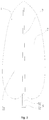
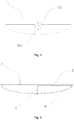
- Curved panel 1 Curved panel 1; curved panel body 11; resistance portion 12; cover plate 2; wind inlet 21; central shaft 3; supporting member 4; connection member 5; connecting rod 51; mounting plate 52; mounting hole 521; jet stream hole 6.
- the wind blade for a wind turbine includes a curved panel 1 which is provided with a concave structure formed on a middle portion thereof, a cover plate 2 which partly covers the concave structure of the curved panel 1 along the edge of the curved panel 1, a central shaft 3 fixed to the cover plate 2, several supporting members 14 which has an end fixed to the central shaft 3 and another end fixed to the curved panel 1, a connection member 5 connecting to an end of the central shaft 3 and a plurality of jet stream holes 6 provided on the curved panel 1 which is covered by the the cover plate 2.
- the curved panel 1 includes a curved panel body 11 and a resistance portion 12.
- the curved panel body 11 has a larger dimension in longitudinal direction than that in transverse direction (it should be noted that the longitudinal direction refers to the direction of the length and the transverse direction refers to the direction of width) and it is symmetrical about its longitudinal center line.
- the resistance portion 12 is a cambered surface and is located on right side of the curved panel 1.
- the jet stream holes 6 are located around or on the resistance portion 12.
- the curved panel 1 is a leaf shaped structure.
- the curved panel body 11 is made of the materials having good performance of anti-solarization, anti-aging and high tenacity.
- the curved panel body 11 is formed by fiberglass layers and epoxy resin layers overlaid with each other in sequence.
- the curved edge of the cover plate 2 has the same shape as that of the edge of the curved panel 1.
- the curved edge of the cover plate 2 is connected to the edge of the curved panel 1 fixedly and hermetically.
- the cover plate 2 includes a straight edge which is parallel to the longitudinal center line of the curved panel 1.
- the cover plate 2 and the curved panel 1 provide a cavity together and the cover plate 2 partly covers the cavity of the curved panel 1.
- the cover plate 2 is made of the materials having good performance of anti-solarization, anti-aging and high tenacity.
- the cover plate 2 is formed by fiberglass layers and epoxy resin layers overlaid with each other.
- the central shaft 3 is a rod or tube made of the materials with high strength and high tenacity.
- the central shaft 3 is a conical structure which has a radius getting large from an upper end to a lower end thereof, that is, it is a conical structure which is small at a top and big at a bottom.
- the central shaft 3 is fixed to the cover plate 2 so as to enhance the structural strength of the wind blade.
- the central shaft 3 is designed to be conical structure so as to reduce the centrifugal force when the wind blade is rotating at high speed and enhance tension intensity of the central shaft 3.
- the supporting member 4 is fixed to the central shaft 3 and the other end thereof is fixed to the curved panel body 11.
- the supporting member 4 could be multiple supporting rods, which are evenly arranged on and fixed to the central shaft 3, and also could be multiple supporting plates 14.
- the supporting member 4 is provided to enhance the structural strength of the wind blade and then enhance the wind-resistant performance thereof, and increase the force bearing area when the wind speed is low, thereby improving the utilization ratio of wind power.
- connection member 5 includes a connecting rod 51 and a mounting plate 52.
- the connecting rod 51 has an end fixedly connecting with the end of the central shaft 3 and another end fixedly connecting with the mounting plate 52.
- the connection member 5 is used to install the curved panel 1 onto a central rotating device of a wind turbine.
- the jet stream holes 16 are elliptic or rounded through-holes formed on the resistance portion 12.
- two or multiple sets of jet stream holes16 are evenly provided on the resistance portion 12 and each set consists of two jet stream holes 16.
- the curved panel 1 could be peach shaped or banana leaf shaped, and it also could be semi-cylinder shaped or semi-cone shaped.
- the curved panel 1 is a leaf shaped panel which has arc-shaped edges and the width of upper part thereof is smaller than that of the lower part thereof.
Landscapes
- Engineering & Computer Science (AREA)
- Life Sciences & Earth Sciences (AREA)
- Sustainable Development (AREA)
- Sustainable Energy (AREA)
- Chemical & Material Sciences (AREA)
- Combustion & Propulsion (AREA)
- Mechanical Engineering (AREA)
- General Engineering & Computer Science (AREA)
- Aviation & Aerospace Engineering (AREA)
- Wind Motors (AREA)
Applications Claiming Priority (2)
| Application Number | Priority Date | Filing Date | Title |
|---|---|---|---|
| CN201410189326.3A CN103939297B (zh) | 2014-05-06 | 2014-05-06 | 用于风电机组的风叶 |
| PCT/CN2014/078964 WO2015168971A1 (fr) | 2014-05-06 | 2014-05-30 | Pale éolienne pour turbine éolienne |
Publications (2)
| Publication Number | Publication Date |
|---|---|
| EP3141742A1 true EP3141742A1 (fr) | 2017-03-15 |
| EP3141742A4 EP3141742A4 (fr) | 2017-05-24 |
Family
ID=51187129
Family Applications (1)
| Application Number | Title | Priority Date | Filing Date |
|---|---|---|---|
| EP14891188.6A Withdrawn EP3141742A4 (fr) | 2014-05-06 | 2014-05-30 | Pale éolienne pour turbine éolienne |
Country Status (4)
| Country | Link |
|---|---|
| US (1) | US20170067440A1 (fr) |
| EP (1) | EP3141742A4 (fr) |
| CN (1) | CN103939297B (fr) |
| WO (1) | WO2015168971A1 (fr) |
Families Citing this family (2)
| Publication number | Priority date | Publication date | Assignee | Title |
|---|---|---|---|---|
| CN104389739A (zh) * | 2014-09-12 | 2015-03-04 | 深圳邦忠风力发电科技股份有限公司 | 新型风叶后置型风电机组 |
| CN117345523A (zh) * | 2023-08-15 | 2024-01-05 | 陕西科乐德农农业科技有限公司 | 一种横轴风力发电机 |
Family Cites Families (15)
| Publication number | Priority date | Publication date | Assignee | Title |
|---|---|---|---|---|
| JP3451085B1 (ja) * | 2002-09-20 | 2003-09-29 | 常夫 野口 | 風力発電用の風車 |
| US9024463B2 (en) * | 2007-03-07 | 2015-05-05 | Daniel N. Boone | Vertical axis wind turbine with multiple flap vanes |
| CN201050443Y (zh) * | 2007-06-25 | 2008-04-23 | 徐道强 | 垂直轴风车或风力发电机叶片 |
| US8282339B2 (en) * | 2007-12-14 | 2012-10-09 | Sankar Terrence C | Vertical axis turbine |
| WO2009078671A2 (fr) * | 2007-12-18 | 2009-06-25 | Jong-Won Park | Appareil de conversion d'énergie comprenant une plaque de pression/charge et appareil de production d'énergie |
| CN201221439Y (zh) * | 2008-07-16 | 2009-04-15 | 肖伟南 | 风力发电机的双层式组合风叶结构 |
| KR100933790B1 (ko) * | 2008-07-31 | 2009-12-24 | 주식회사 시그너스파워 | 수직축형 다리우스 풍차 |
| JP5116040B2 (ja) * | 2009-01-05 | 2013-01-09 | 株式会社辰巳菱機 | 風力発電用風車 |
| KR101073096B1 (ko) * | 2009-10-05 | 2011-10-12 | 윤양일 | 수직축형 다리우스 풍차 |
| US8905704B2 (en) * | 2010-11-15 | 2014-12-09 | Sauer Energy, Inc. | Wind sail turbine |
| CN102189197B (zh) * | 2011-04-02 | 2013-04-10 | 唐山市拓又达科技有限公司 | 垂直轴风力发电机扇叶成型机 |
| CN202194772U (zh) * | 2011-07-25 | 2012-04-18 | 易荣任 | 水平轴渐开线螺旋面叶片 |
| GB2498973A (en) * | 2012-02-01 | 2013-08-07 | Mark Bloomfield | Turbine scoop formed from a plurality of spaced flat plates |
| CN103306892B (zh) * | 2012-04-18 | 2016-04-27 | 王政玉 | 一种动力翼片 |
| CN203906186U (zh) * | 2014-05-06 | 2014-10-29 | 耿志伟 | 用于风电机组的风叶 |
-
2014
- 2014-05-06 CN CN201410189326.3A patent/CN103939297B/zh not_active Expired - Fee Related
- 2014-05-30 EP EP14891188.6A patent/EP3141742A4/fr not_active Withdrawn
- 2014-05-30 US US15/308,839 patent/US20170067440A1/en not_active Abandoned
- 2014-05-30 WO PCT/CN2014/078964 patent/WO2015168971A1/fr not_active Ceased
Also Published As
| Publication number | Publication date |
|---|---|
| EP3141742A4 (fr) | 2017-05-24 |
| US20170067440A1 (en) | 2017-03-09 |
| WO2015168971A1 (fr) | 2015-11-12 |
| CN103939297A (zh) | 2014-07-23 |
| CN103939297B (zh) | 2016-08-17 |
Similar Documents
| Publication | Publication Date | Title |
|---|---|---|
| EP2314867A2 (fr) | Éolienne darius de type à axe vertical | |
| US20160215756A1 (en) | Wind turbine generator compatible with high and low wind speeds | |
| US8162589B2 (en) | Moving fluid energy recovery system | |
| EP3141742A1 (fr) | Pale éolienne pour turbine éolienne | |
| CN104863792B (zh) | 具有扭角的垂直轴风力机弯曲叶片 | |
| EP3147500B1 (fr) | Éolienne à axe vertical et à puissance de sortie régulable | |
| KR20120133331A (ko) | 풍력발전기용 소음저감 블레이드 | |
| KR100986155B1 (ko) | 고효율 수직형 풍력 발전기 | |
| KR20090051669A (ko) | 풍력발전용 집풍형 풍차 | |
| Almukhtar | Effect of drag on the performance for an efficient wind turbine blade design | |
| CN206458561U (zh) | 一种叶尖设有环翼的高性能风力机叶片 | |
| CN215057878U (zh) | 一种低雷诺数叶片翼型及应用其的水平轴风力机 | |
| CN105545583B (zh) | 风力发电叶片及背风面出流切线倾角的确定方法 | |
| KR101418674B1 (ko) | 루버유도형 풍력발전기 | |
| Hsieh et al. | Experimental study on performance of vertical axis wind turbine with NACA 4-digital series of blades | |
| CN101943108B (zh) | 一种垂直轴风力机的自起动装置 | |
| CN204175524U (zh) | 一种双环多叶片风力发电装置 | |
| US8202051B2 (en) | Turbine apparatus | |
| CA2532597A1 (fr) | Cycloturbine | |
| CN203906186U (zh) | 用于风电机组的风叶 | |
| CN101943112B (zh) | 一种垂直轴风力机的风轮装置 | |
| CN118224032B (zh) | 一种海上风力发电叶片的自动调节方法和装置 | |
| CN204175526U (zh) | 风叶和包括该风叶的垂直轴风力发电机 | |
| CN111927707B (zh) | 一种风力发电机叶片 | |
| CN201786553U (zh) | 一种垂直轴风力机的风轮装置 |
Legal Events
| Date | Code | Title | Description |
|---|---|---|---|
| PUAI | Public reference made under article 153(3) epc to a published international application that has entered the european phase |
Free format text: ORIGINAL CODE: 0009012 |
|
| 17P | Request for examination filed |
Effective date: 20161206 |
|
| AK | Designated contracting states |
Kind code of ref document: A1 Designated state(s): AL AT BE BG CH CY CZ DE DK EE ES FI FR GB GR HR HU IE IS IT LI LT LU LV MC MK MT NL NO PL PT RO RS SE SI SK SM TR |
|
| AX | Request for extension of the european patent |
Extension state: BA ME |
|
| A4 | Supplementary search report drawn up and despatched |
Effective date: 20170425 |
|
| RIC1 | Information provided on ipc code assigned before grant |
Ipc: F03D 1/06 20060101AFI20170419BHEP Ipc: F03D 3/06 20060101ALI20170419BHEP Ipc: F03D 5/00 20060101ALI20170419BHEP |
|
| DAX | Request for extension of the european patent (deleted) | ||
| STAA | Information on the status of an ep patent application or granted ep patent |
Free format text: STATUS: THE APPLICATION IS DEEMED TO BE WITHDRAWN |
|
| 18D | Application deemed to be withdrawn |
Effective date: 20171123 |