EP3141745A1 - Windturbinenstromerzeugungsvorrichtung und verfahren zur verbindung davon - Google Patents
Windturbinenstromerzeugungsvorrichtung und verfahren zur verbindung davon Download PDFInfo
- Publication number
- EP3141745A1 EP3141745A1 EP16167105.2A EP16167105A EP3141745A1 EP 3141745 A1 EP3141745 A1 EP 3141745A1 EP 16167105 A EP16167105 A EP 16167105A EP 3141745 A1 EP3141745 A1 EP 3141745A1
- Authority
- EP
- European Patent Office
- Prior art keywords
- connection
- wind turbine
- pitch
- pitch angle
- generator
- Prior art date
- Legal status (The legal status is an assumption and is not a legal conclusion. Google has not performed a legal analysis and makes no representation as to the accuracy of the status listed.)
- Withdrawn
Links
Images



Classifications
-
- F—MECHANICAL ENGINEERING; LIGHTING; HEATING; WEAPONS; BLASTING
- F03—MACHINES OR ENGINES FOR LIQUIDS; WIND, SPRING, OR WEIGHT MOTORS; PRODUCING MECHANICAL POWER OR A REACTIVE PROPULSIVE THRUST, NOT OTHERWISE PROVIDED FOR
- F03D—WIND MOTORS
- F03D7/00—Controlling wind motors
- F03D7/02—Controlling wind motors the wind motors having rotation axis substantially parallel to the air flow entering the rotor
- F03D7/026—Controlling wind motors the wind motors having rotation axis substantially parallel to the air flow entering the rotor for starting-up
-
- F—MECHANICAL ENGINEERING; LIGHTING; HEATING; WEAPONS; BLASTING
- F03—MACHINES OR ENGINES FOR LIQUIDS; WIND, SPRING, OR WEIGHT MOTORS; PRODUCING MECHANICAL POWER OR A REACTIVE PROPULSIVE THRUST, NOT OTHERWISE PROVIDED FOR
- F03D—WIND MOTORS
- F03D7/00—Controlling wind motors
- F03D7/02—Controlling wind motors the wind motors having rotation axis substantially parallel to the air flow entering the rotor
- F03D7/022—Adjusting aerodynamic properties of the blades
- F03D7/0224—Adjusting blade pitch
-
- F—MECHANICAL ENGINEERING; LIGHTING; HEATING; WEAPONS; BLASTING
- F03—MACHINES OR ENGINES FOR LIQUIDS; WIND, SPRING, OR WEIGHT MOTORS; PRODUCING MECHANICAL POWER OR A REACTIVE PROPULSIVE THRUST, NOT OTHERWISE PROVIDED FOR
- F03D—WIND MOTORS
- F03D7/00—Controlling wind motors
- F03D7/02—Controlling wind motors the wind motors having rotation axis substantially parallel to the air flow entering the rotor
- F03D7/0276—Controlling wind motors the wind motors having rotation axis substantially parallel to the air flow entering the rotor controlling rotor speed, e.g. variable speed
-
- F—MECHANICAL ENGINEERING; LIGHTING; HEATING; WEAPONS; BLASTING
- F03—MACHINES OR ENGINES FOR LIQUIDS; WIND, SPRING, OR WEIGHT MOTORS; PRODUCING MECHANICAL POWER OR A REACTIVE PROPULSIVE THRUST, NOT OTHERWISE PROVIDED FOR
- F03D—WIND MOTORS
- F03D7/00—Controlling wind motors
- F03D7/02—Controlling wind motors the wind motors having rotation axis substantially parallel to the air flow entering the rotor
- F03D7/028—Controlling wind motors the wind motors having rotation axis substantially parallel to the air flow entering the rotor controlling wind motor output power
- F03D7/0284—Controlling wind motors the wind motors having rotation axis substantially parallel to the air flow entering the rotor controlling wind motor output power in relation to the state of the electric grid
-
- F—MECHANICAL ENGINEERING; LIGHTING; HEATING; WEAPONS; BLASTING
- F03—MACHINES OR ENGINES FOR LIQUIDS; WIND, SPRING, OR WEIGHT MOTORS; PRODUCING MECHANICAL POWER OR A REACTIVE PROPULSIVE THRUST, NOT OTHERWISE PROVIDED FOR
- F03D—WIND MOTORS
- F03D7/00—Controlling wind motors
- F03D7/02—Controlling wind motors the wind motors having rotation axis substantially parallel to the air flow entering the rotor
- F03D7/04—Automatic control; Regulation
- F03D7/042—Automatic control; Regulation by means of an electrical or electronic controller
-
- F—MECHANICAL ENGINEERING; LIGHTING; HEATING; WEAPONS; BLASTING
- F03—MACHINES OR ENGINES FOR LIQUIDS; WIND, SPRING, OR WEIGHT MOTORS; PRODUCING MECHANICAL POWER OR A REACTIVE PROPULSIVE THRUST, NOT OTHERWISE PROVIDED FOR
- F03D—WIND MOTORS
- F03D9/00—Adaptations of wind motors for special use; Combinations of wind motors with apparatus driven thereby; Wind motors specially adapted for installation in particular locations
- F03D9/20—Wind motors characterised by the driven apparatus
- F03D9/25—Wind motors characterised by the driven apparatus the apparatus being an electrical generator
- F03D9/255—Wind motors characterised by the driven apparatus the apparatus being an electrical generator connected to electrical distribution networks; Arrangements therefor
-
- F—MECHANICAL ENGINEERING; LIGHTING; HEATING; WEAPONS; BLASTING
- F05—INDEXING SCHEMES RELATING TO ENGINES OR PUMPS IN VARIOUS SUBCLASSES OF CLASSES F01-F04
- F05B—INDEXING SCHEME RELATING TO WIND, SPRING, WEIGHT, INERTIA OR LIKE MOTORS, TO MACHINES OR ENGINES FOR LIQUIDS COVERED BY SUBCLASSES F03B, F03D AND F03G
- F05B2220/00—Application
- F05B2220/30—Application in turbines
-
- F—MECHANICAL ENGINEERING; LIGHTING; HEATING; WEAPONS; BLASTING
- F05—INDEXING SCHEMES RELATING TO ENGINES OR PUMPS IN VARIOUS SUBCLASSES OF CLASSES F01-F04
- F05B—INDEXING SCHEME RELATING TO WIND, SPRING, WEIGHT, INERTIA OR LIKE MOTORS, TO MACHINES OR ENGINES FOR LIQUIDS COVERED BY SUBCLASSES F03B, F03D AND F03G
- F05B2260/00—Function
- F05B2260/70—Adjusting of angle of incidence or attack of rotating blades
- F05B2260/74—Adjusting of angle of incidence or attack of rotating blades by turning around an axis perpendicular the rotor centre line
-
- F—MECHANICAL ENGINEERING; LIGHTING; HEATING; WEAPONS; BLASTING
- F05—INDEXING SCHEMES RELATING TO ENGINES OR PUMPS IN VARIOUS SUBCLASSES OF CLASSES F01-F04
- F05B—INDEXING SCHEME RELATING TO WIND, SPRING, WEIGHT, INERTIA OR LIKE MOTORS, TO MACHINES OR ENGINES FOR LIQUIDS COVERED BY SUBCLASSES F03B, F03D AND F03G
- F05B2260/00—Function
- F05B2260/85—Starting
-
- F—MECHANICAL ENGINEERING; LIGHTING; HEATING; WEAPONS; BLASTING
- F05—INDEXING SCHEMES RELATING TO ENGINES OR PUMPS IN VARIOUS SUBCLASSES OF CLASSES F01-F04
- F05B—INDEXING SCHEME RELATING TO WIND, SPRING, WEIGHT, INERTIA OR LIKE MOTORS, TO MACHINES OR ENGINES FOR LIQUIDS COVERED BY SUBCLASSES F03B, F03D AND F03G
- F05B2270/00—Control
- F05B2270/10—Purpose of the control system
- F05B2270/101—Purpose of the control system to control rotational speed (n)
-
- F—MECHANICAL ENGINEERING; LIGHTING; HEATING; WEAPONS; BLASTING
- F05—INDEXING SCHEMES RELATING TO ENGINES OR PUMPS IN VARIOUS SUBCLASSES OF CLASSES F01-F04
- F05B—INDEXING SCHEME RELATING TO WIND, SPRING, WEIGHT, INERTIA OR LIKE MOTORS, TO MACHINES OR ENGINES FOR LIQUIDS COVERED BY SUBCLASSES F03B, F03D AND F03G
- F05B2270/00—Control
- F05B2270/30—Control parameters, e.g. input parameters
- F05B2270/309—Rate of change of parameters
-
- F—MECHANICAL ENGINEERING; LIGHTING; HEATING; WEAPONS; BLASTING
- F05—INDEXING SCHEMES RELATING TO ENGINES OR PUMPS IN VARIOUS SUBCLASSES OF CLASSES F01-F04
- F05B—INDEXING SCHEME RELATING TO WIND, SPRING, WEIGHT, INERTIA OR LIKE MOTORS, TO MACHINES OR ENGINES FOR LIQUIDS COVERED BY SUBCLASSES F03B, F03D AND F03G
- F05B2270/00—Control
- F05B2270/30—Control parameters, e.g. input parameters
- F05B2270/32—Wind speeds
-
- F—MECHANICAL ENGINEERING; LIGHTING; HEATING; WEAPONS; BLASTING
- F05—INDEXING SCHEMES RELATING TO ENGINES OR PUMPS IN VARIOUS SUBCLASSES OF CLASSES F01-F04
- F05B—INDEXING SCHEME RELATING TO WIND, SPRING, WEIGHT, INERTIA OR LIKE MOTORS, TO MACHINES OR ENGINES FOR LIQUIDS COVERED BY SUBCLASSES F03B, F03D AND F03G
- F05B2270/00—Control
- F05B2270/30—Control parameters, e.g. input parameters
- F05B2270/327—Rotor or generator speeds
-
- F—MECHANICAL ENGINEERING; LIGHTING; HEATING; WEAPONS; BLASTING
- F05—INDEXING SCHEMES RELATING TO ENGINES OR PUMPS IN VARIOUS SUBCLASSES OF CLASSES F01-F04
- F05B—INDEXING SCHEME RELATING TO WIND, SPRING, WEIGHT, INERTIA OR LIKE MOTORS, TO MACHINES OR ENGINES FOR LIQUIDS COVERED BY SUBCLASSES F03B, F03D AND F03G
- F05B2270/00—Control
- F05B2270/30—Control parameters, e.g. input parameters
- F05B2270/328—Blade pitch angle
-
- F—MECHANICAL ENGINEERING; LIGHTING; HEATING; WEAPONS; BLASTING
- F05—INDEXING SCHEMES RELATING TO ENGINES OR PUMPS IN VARIOUS SUBCLASSES OF CLASSES F01-F04
- F05B—INDEXING SCHEME RELATING TO WIND, SPRING, WEIGHT, INERTIA OR LIKE MOTORS, TO MACHINES OR ENGINES FOR LIQUIDS COVERED BY SUBCLASSES F03B, F03D AND F03G
- F05B2270/00—Control
- F05B2270/30—Control parameters, e.g. input parameters
- F05B2270/337—Electrical grid status parameters, e.g. voltage, frequency or power demand
-
- Y—GENERAL TAGGING OF NEW TECHNOLOGICAL DEVELOPMENTS; GENERAL TAGGING OF CROSS-SECTIONAL TECHNOLOGIES SPANNING OVER SEVERAL SECTIONS OF THE IPC; TECHNICAL SUBJECTS COVERED BY FORMER USPC CROSS-REFERENCE ART COLLECTIONS [XRACs] AND DIGESTS
- Y02—TECHNOLOGIES OR APPLICATIONS FOR MITIGATION OR ADAPTATION AGAINST CLIMATE CHANGE
- Y02E—REDUCTION OF GREENHOUSE GAS [GHG] EMISSIONS, RELATED TO ENERGY GENERATION, TRANSMISSION OR DISTRIBUTION
- Y02E10/00—Energy generation through renewable energy sources
- Y02E10/70—Wind energy
- Y02E10/72—Wind turbines with rotation axis in wind direction
Definitions
- the present disclosure relates to a wind turbine power generating apparatus and a method of connecting the same.
- an anemometer disposed on an upper part of a wind turbine power generating apparatus firstly measures the wind speed around a wind turbine rotor, and if an average wind speed in a predetermined period exceeds a cut-in wind speed, the pitch angle of blades is changed from a feather side toward a fine side to start rotation of the wind turbine rotor, thereby starting the wind turbine power generating apparatus.
- the rotation speed of the wind turbine rotor or the rotation speed of a generator
- the wind turbine power generating apparatus is connected to the utility grid.
- Patent Document 1 discloses a method of changing the pitch angle of blades from the feather side toward the fine side at a constant rate, and matching a generator rotation speed with a connection rotation speed by adjusting the pitch angle if the generator rotation speed exceeds the connection rotation speed.
- Patent Document 2 discloses a method of increasing the rotation speed of a wind turbine rotor by changing the pitch angle of blades from the feather side toward the fine side in stages before connection to a utility gird.
- a generator when a wind turbine power generating apparatus is to be connected, a generator is connected to the utility grid at a rotation speed of a wind turbine rotor (or a generator rotation speed) being controlled to a rotation speed suitable for connection (connection rotation speed), so as not to negatively affect the utility grid.
- connection rotation speed a rotation speed suitable for connection
- a wind turbine power generating apparatus cannot be smoothly connected even if the rotation speed of the wind turbine rotor is satisfying a connection condition. For instance, if the wind speed is relatively low even though the generator rotation speed has reached the connection rotation speed, the generator rotation speed may decrease to the disconnection rotation speed or below immediately after connection of the generator, and the generator may disconnect shortly. Further, if the generator rotation speed reaches the connection rotation speed again after disconnection of the generator, the generator connected again. If the wind speed is continuously low, connection and disconnection may be repeated. As a result, a circuit breaker for controlling connection of the generator opens and closes frequently, which may shorten the lifetime of the circuit breaker.
- Patent Documents 1 and 2 disclose a method of increasing the rotation speed of the generator to a connection rotation speed suitably, but do not disclose a specific measure to avoid occurrence of disconnection immediately after connection, or repetitive disconnections and connections.
- a wind turbine rotor it is determined whether a wind turbine rotor can or cannot be started on the basis of a wind speed measured by an anemometer. In this case, it is difficult to accurately determine wind energy received by a wind turbine rotor as a whole. If the wind speed is measured by an anemometer at points, the wind speed may greatly vary depending on the position of the anemometer even at the same time under great wind-shear condition (wind-speed variation in a vertical direction), which makes it difficult to start or connect a wind turbine power generating apparatus appropriately.
- an object of at least some embodiments of the present invention is to provide a wind turbine power generating apparatus and a method of connecting the wind turbine power generating apparatus, whereby it is possible to avoid repetition of connections and disconnections upon connection of the wind turbine power generating apparatus, and to connect the wind turbine power generating apparatus to a utility grid smoothly.
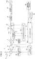
- FIG. 1 is a block diagram of a schematic configuration of the wind turbine power generating apparatus 1 according to an embodiment.
- FIG. 2 is a block diagram of a specific configuration of the wind turbine power generating apparatus 1 according to an embodiment.
- FIG. 3 is a time chart showing a time-series change of each parameter of the wind turbine power generating apparatus 1 according to an embodiment.
- the wind turbine power generating apparatus 1 is configured to generate electric power from wind energy. More specifically, the wind turbine power generating apparatus 1 is provided as a power source of a dispersed power system and configured to be connectable to a grid (utility grid) 100.
- the wind turbine power generating apparatus 1 may be an offshore wind turbine power generating apparatus or an onshore wind turbine power generating apparatus.
- the wind turbine power generating apparatus 1 includes a wind turbine rotor 2, a pitch drive part 20, a generator 7, a circuit breaker 10, and a controller 30.
- the wind turbine power generating apparatus 1 may include a pitch-angle sensor 22 for detecting the pitch angle of a blade 3 of the wind turbine rotor 2, an anemometer 26 for measuring a wind speed in the vicinity of the wind turbine rotor 2, and at least one of a rotation-speed sensor 24 for detecting a rotation speed of the wind turbine rotor 2 (rotor rotation speed), or a rotation-speed sensor 25 for detecting a rotation speed of the generator 7 (generator rotation speed).
- a pitch-angle sensor 22 for detecting the pitch angle of a blade 3 of the wind turbine rotor 2
- an anemometer 26 for measuring a wind speed in the vicinity of the wind turbine rotor 2
- a rotation-speed sensor 24 for detecting a rotation speed of the wind turbine rotor 2 (rotor rotation speed)
- a rotation-speed sensor 25 for detecting a rotation speed of the generator 7 (generator rotation speed).
- the rotor rotation speed and the generator rotation speed correspond to each other at a constant ratio, either one may
- the wind turbine rotor 2 includes at least one blade 3.
- the wind turbine rotor 2 may include a part which rotates integrally with the at least one blade 3 when the at least one blade 3 receives wind.
- the wind turbine rotor 2 includes a plurality of blades 3 radially mounted to a hub 4, and is configured such that the blades 3 and the hub 4 integrally rotate when the blades 3 receive wind.
- the wind turbine rotor 2 may further include a main shaft 5 connected to the hub 4, in addition to the blades 3 and the hub 4.
- the pitch drive part 20 is configured to change the pitch angle of the blades 3.
- the pitch drive part 20 is a pitch actuator for changing the pitch angle of the blades 3 on the basis of a pitch command of the pitch control part 31 described below.
- the pitch drive part 20 may be a mechanical actuator such as a hydraulic cylinder and a pneumatic cylinder, or an electric actuator such as a servo motor.
- the pitch drive part 20 may be disposed inside the hub 4. In a case in which the wind turbine rotor 2 has a plurality of blades 3, the pitch drive part 20 may be disposed on each of the plurality of blades 3.
- the generator 7 is configured to be driven by rotational energy of the rotor 2.
- the generator 7 may be an induction generator or a synchronous generator.
- the generator 7 is a secondary-winding induction generator.
- the secondary-winding induction generator 7 has a stator winding directly connected to a grid 100 and a rotor winding connected to the grid 100 via a power converter (e.g. AC-DC-AC converter) 12.
- the power converter 12 controls electric current of the rotor winding to adjust a generator torque, thereby enabling variable-speed operation, and also converts power received from the rotor winding of the secondary-winding induction generator 7 to AC that matches a frequency of the grid 100.
- a drivetrain 6 may be disposed between the wind turbine rotor 2 and the generator 7.
- the drivetrain 6 may be a gear-type drivetrain, or a hydraulic transmission including a hydraulic pump and a hydraulic motor connected to each other through hydraulic lines.
- the wind turbine rotor 2 and the generator 7 may be coupled directly to each other.
- the circuit breaker 10 is configured to switch a connection state of the generator 7 with respect to the grid 100.
- the circuit breaker 10 is controlled to be opened and closed by a controller 30.
- a stator circuit breaker 10a is disposed in a line 11a connected to the stator winding of the secondary-winding induction generator 7.
- a rotor circuit breaker 10b is disposed in a line 11b connected to the rotor winding of the secondary-winding induction generator 7, at the grid 100 side of the power converter 12.
- the rotor circuit breaker 10b is controlled to open and close by a converter controller 42 described below.
- an electric transformer 14 for transforming AC voltage generated by the generator 7 and converted into AC by the power converter 12, and a power source switching board 16 for switching a load current in normal time are disposed.
- the controller 30 is configured to control the wind turbine power generating apparatus 1.
- the controller 30 includes a pitch control part 31, a connection-condition determination part 34, and a connection-command generation part 35.
- the controller 30 is depicted as a physically integrated object having a plurality of functions such as the pitch control part 31, the connection-condition determination part 34, and the connection-command generation part 35.
- the controller 30 may include a plurality of devices disposed physically distant from one another.
- the controller 30 includes a WTC controller 40, a pitch controller 41, and the converter controller 42.
- the WTC controller 40 and the converter controller 42 may be disposed inside a nacelle, and the pitch controller 41 may be disposed inside the hub 4.
- the pitch control part 31 controls the pitch drive part 20 in the constant rotation-speed control mode 50 (see FIG. 3 ) for maintaining the rotation speed of the wind turbine rotor 2 (rotor rotation speed) at a target rotation speed, before connection of the generator 7. Specifically, in the constant rotation-speed control mode in a no-load state, the pitch angle of the blades 3 is changed in accordance with the wind speed so that the wind turbine rotor maintains the target rotation speed.
- the pitch control part 31 is configured to control the pitch drive part 20 in accordance with a mode selected from a plurality of modes including the above constant rotation-speed control mode and a pitch-schedule control mode.
- a pitch schedule mode is a mode in which the pitch angle is changed from a feather side toward a fine side at one or more pitch rate set in advance, for instance.
- the pitch control part 31 (see FIG. 1 ) may be included in the pitch controller 41.
- the connection-condition determination part 34 is configured to determine whether a connection-determination condition including at least the first condition is satisfied.
- the first condition is a condition that, while the pitch drive part 20 is being controlled in the constant rotation-speed control mode, the pitch angle is at a feather side of a connection determination pitch angle for a period of ⁇ T 1 or longer.
- ⁇ T 1 may be from 10 to 50 seconds. Alternatively, ⁇ T 1 may be from 20 to 40 seconds. Further, ⁇ T 1 may be variable and set suitably in accordance with experience, a wind-speed condition, or the like.
- connection-command generation part 35 provides the circuit breaker 10 with a connection command so as to connect the generator 7 to the grid 100 if the connection-condition determination part 34 determines that the connection-determination condition is satisfied.
- connection-condition determination part 34 and the connection-command generation part 35 may be included in the WTC controller 40.
- the pitch control part 31 controls the pitch drive part 20 in the constant rotation-speed control mode for maintaining the rotation speed of the wind turbine rotor 2 at a target rotation speed, before connection of the generator 7.
- connection at a rotation speed controlled to be constant is relatively easy, which makes it possible to reduce the risk of connection failure.
- connection-condition determination part 34 determines whether the connection determination condition including at least the first condition is satisfied, and if satisfied, the connection-command generation part 35 provides the circuit breaker 10 with a connection command to connect the generator 7 to the grid 100.
- the pitch angle is adjusted so as to maintain the rotation speed of the wind turbine rotor 2 at a target rotation speed.
- a pitch angle at this time has a correlation with the wind speed (the wind speed and the pitch angle have a correlation).
- the wind speed here is not a wind speed at "a point” measured by an anemometer, but a wind speed received by "a plane” of the wind turbine rotor as a whole, which is wind energy received by the entire rotor plane of the wind turbine rotor.
- FIG. 4 is a graph showing a relationship between a wind speed and a pitch angle in a constant rotation-speed control mode. As illustrated in the drawing, in the constant rotation-speed control mode, the pitch angle is changed in accordance with the wind speed so that the rotor rotation speed is at a constant value. Thus, the pitch angle and the wind speed have a proportional relationship.
- the pitch angle in the constant rotation-speed control mode is used as a conceptual anemometer for determining wind energy received by the entire rotor plane of the wind turbine rotor 2. For instance, if the pitch angle is on the feather side of the connection-determination pitch angle for a predetermined period or longer, it can be determined that the wind turbine rotor 2 is receiving sufficient wind energy.
- connection determination condition may include the second condition that, while the pitch drive part 20 is controlled in the constant rotation-speed control mode, a difference between the rotation speed of the wind turbine rotor 2 and the target rotation speed falls within an allowable range for a period of ⁇ T 2 or longer.
- ⁇ T 2 may be from 10 to 50 seconds.
- ⁇ T 2 may be from 20 to 40 seconds.
- ⁇ T 2 may be variable and be set suitably in accordance with experience, a wind-speed condition, or the like.
- the generator 7 can be connected while the rotation speed of the wind turbine rotor 2 is maintained at a target rotation speed or at a rotation speed close to the target rotation speed, which makes it possible to reduce the risk of failure in connection of the generator 7 even more effectively.
- a controller for controlling the circuit breaker 10 for instance, the converter controller 42
- a high increasing rate of the rotation speed due to a high wind speed during connection of a wind turbine power generating apparatus may make it difficult to synchronize the voltage, the frequency, and the amplitude and require a longer time to complete the connection, thus resulting in issuance of a connection-failure alert.
- the rotation speed of the wind turbine rotor 2 is maintained at a target rotation speed or at a rotation speed close to the target rotation speed, which makes it possible for the converter controller 42 to perform the connecting operation easily.
- the controller 30 may include at least one of a smoothing part 32, a pitch-angle selection part 33, a synchronization determination part 36, or a stop-command generation part 37.
- the pitch-angle selection part 33 is configured to select a connection determination pitch angle to be used as a connection determination condition from among a plurality of kinds of connection determination pitch angles.
- connection determination pitch angle is suitably selected in accordance with a state (e.g. the switching frequency) of the circuit breaker 10, which makes it possible to reduce unnecessary switching of the circuit breaker 10.
- connection determination pitch angle selected from among a plurality of kinds of connection determination pitch angles to be used as the connection determination condition is changed suitably in accordance with experience. Accordingly, it is possible to set a more suitable connection-determination condition corresponding to the surrounding environment of the wind turbine power generating apparatus 1.
- the pitch-angle selection part 33 may select a connection determination pitch angle in accordance with the cumulative switching number of the circuit breaker 10.
- connection determination pitch angle closer to the feather side from among the plurality of kinds of connection determination pitch angles makes it possible to reduce the cumulative switching number of the circuit breaker 10 effectively and to extend the lifetime of the circuit breaker 10.
- a connection determination pitch angle closer to the fine side may be selected from among the plurality of kinds of connection determination pitch angles.
- the smoothing part 32 is configured to smooth a pitch angle while the pitch drive part 20 is being controlled in the constant rotation-speed control mode, thereby obtaining a smoothed pitch angle.
- the smoothing part 32 includes a primary-delay lowpass filter and obtains a smoothed pitch angle by performing primary-delay lowpass filtering on pitch-angle data of a predetermined time obtained by the pitch-angle sensor 22.
- connection-condition determination part 34 is configured to compare the smoothed pitch angle with the connection determination pitch angle, so as to determine whether the first condition is satisfied.
- the smoothed pitch angle which is a pitch angle having been smoothed
- the connection determination pitch angle are compared, so as to determine whether the first condition is satisfied. In this way, it is possible to determine a connection condition suitably even if the pitch angle changes while the pitch drive part is controlled in the constant rotation-speed control mode.
- the stop-command generation part 37 is configured to generate a stop command for causing the wind turbine power generating apparatus 1 to shift to a stop mode, if the rotation speed of the generator exceeds a threshold value greater than a connection schedule rotation speed at which the generator 7 is connected.
- a stop mode of the wind turbine power generating apparatus 1 is, for instance, a mode for stopping the wind turbine rotor 2 so that maintenance can be performed on the wind turbine power generating apparatus 1.
- the stop-command generation part 37 may be included in the WTC controller 40.
- the WTC controller 40 may be configured such that data is transmittable between the WTC controller 40 and an input-output part 44 provided separately, such as a touch panel. Further, the WTC controller 40 may be configured such that data is transmittable between the WTC controller 40 and a remote monitoring device 45 installed on a place remote from the wind turbine power generating apparatus 1.
- the wind turbine power generating apparatus 1 is shifted to the stop mode if the rotor rotation speed becomes excessively high.
- the pitch control part 31 includes a pitch rate limiter for limiting a change rate of the pitch angle changing toward the fine side after connection of the generator 7 for the change rate to be lower or equal to an upper limit value.
- the synchronization determination part 36 is configured to determine whether a difference between the voltage, phase, and frequency of the generator 7 and those of the grid 100 have fallen in a synchronization-enabled range, in response to a connection command from the connection-command generation part 35.
- the synchronization determination part 36 (see FIG. 1 ) may be included in the WTC controller 40.
- the circuit breaker 10 is configured to close if the synchronization determination part 36 determines that the difference has fallen in the synchronization-enabled range.
- the generator 7 is connected when the voltage, phase, and frequency of the generator 7 are at appropriate values. Thus, it is possible to prevent negative influence of connection from being imposed on the grid 100 by the generator 7, which enables smooth connection of the wind turbine power generating apparatus 1.
- the pitch control part 31 is configured to control the pitch drive part 20 so that, when the rotation speed of the wind turbine rotor 2 decreases to a disconnection rotation speed or lower so that the generator 7 disconnects, the pitch angle changes to the feather side to be maintained at a standby pitch angle.
- FIG. 5 is a flowchart schematically showing a method of connecting a wind turbine power generating apparatus according to an embodiment.
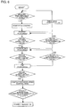
- FIG. 6 is a flowchart specifically showing a method of connecting a wind turbine power generating apparatus according to an embodiment.
- the reference signs illustrated in FIG. 1 will be used where appropriate.
- the wind turbine power generating apparatus 1 includes the wind turbine rotor 2 including the at least one blade 3, the pitch drive part 20 for changing the pitch angle of the at least one blade 3, the generator 7 configured to be driven by rotation energy of the wind turbine rotor 2, and the circuit breaker 10 for switching a connection state of the generator 7 to the grid 100.
- the method of connecting the wind turbine power generating apparatus 1 includes a pitch control step S2, a connection-condition determination step S5, and a connection-command generation step S6.
- the method of connecting the wind turbine power generating apparatus 1 may further includes at least one of a starting step S1, a smoothing step S4, a pitch-angle selection step S3, or a synchronization determination step S7.
- the wind turbine power generating apparatus 1 is started if a mean value of wind speed (mean wind speed) in a predetermined time measured by the anemometer 26 exceeds a startup wind speed set in advance.
- the pitch drive part 20 is controlled in the constant rotation-speed control mode for maintaining the rotation speed of the wind turbine rotor 2 at a target rotation speed, before connection of the generator 7.
- connection-condition determination step S5 it is determined whether a connection determination condition is satisfied (S5-1), the connection determination condition at least including the first condition that, while the pitch drive part 20 is being controlled in the constant rotation-speed control mode, a pitch angle is at a feather side of a connection determination pitch angle continuously for a period of ⁇ T 1 or longer.
- connection-condition determination step S5 it may be determined whether a connection determination condition is satisfied (S5-2), the connection determination condition further including the second condition that a difference between the rotation speed of the wind turbine rotor 2 and the target rotation speed falls within an allowable range continuously for a period of ⁇ T 2 or longer.
- connection-command generation step S6 the circuit breaker 10 is provided with a connection command to connect the generator 7 to the grid 100 if it is determined that the connection-determination condition is satisfied in the connection-condition determination step S5.
- the pitch drive part is controlled in the constant rotation-speed control mode for maintaining the rotation speed of the wind turbine rotor 2 at a target rotation speed, before connection of the generator 7.
- connection at a rotation speed controlled to be constant is relatively easy, which makes it possible to reduce the risk of connection failure.
- connection determination condition including at least the first condition is satisfied in the connection-condition determination step S5
- the circuit breaker 10 is provided with a connection command to connect the generator 7 to the grid 100 in the connection-command generation step S6.
- the above method it is possible to determine, from a pitch angle, whether a sufficient wind speed is achieved for the entire rotor plane of the wind turbine rotor 2 when the generator 7 is to be connected. In this way, it is possible to prevent disconnection of the generator 7 and repetition of disconnections and connections of the generator 7 immediately after connection, which makes it possible to reduce switching frequency of the circuit breaker 10, to prevent a decrease in the lifetime of the circuit breaker 10, and to maintain a stable connection state of the wind turbine power generating apparatus 1 to the grid 100.
- a connection determination pitch angle to be used as a connection determination condition is selected from among a plurality of kinds of connection determination pitch angles.
- connection determination pitch angle is suitably selected in accordance with a state (e.g. the switching frequency) of the circuit breaker 10, which makes it possible to reduce unnecessary switching of the circuit breaker.
- connection determination pitch angle selected from among a plurality of kinds of connection determination pitch angles to be used as the connection determination condition is changed suitably in accordance with experience. Accordingly, it is possible to set a suitable connection-determination condition corresponding to the surrounding environment of the wind turbine power generating apparatus 1.
- a connection determination pitch angle may be selected in accordance with the cumulative switching number of the circuit breaker 10.
- connection determination pitch angle closer to the feather side from among the plurality of kinds of connection determination pitch angles makes it possible to reduce the cumulative switching number of the circuit breaker 10 effectively and to extend the lifetime of the circuit breaker 10.
- a connection determination pitch angle closer to the fine side may be selected from among the plurality of kinds of connection determination pitch angles.
- a pitch angle while the pitch drive part 20 is being controlled in the constant rotation-speed control mode is smoothed to obtain a smoothed pitch angle.
- connection-condition determination step S5 the smoothed pitch angle is compared with the connection determination pitch angle, so as to determine whether the first condition is satisfied.
- a change rate of the pitch angle changing toward the fine side after connection of the generator 7 may be limited to be not greater than an upper limit value.
- FIG. 6 a method of connecting the wind turbine power generating apparatus 1 according to an embodiment will be described specifically.
- FIGs. 1 to 3 will be also referred to where appropriate.
- the wind turbine power generating apparatus 1 is started and pitch control is started, if a mean value (mean wind speed) in the predetermined time of wind speed measured by the anemometer 26 exceeds a startup wind speed set in advance.
- a standby state shifts to a startup state.
- the pitch drive part 20 is controlled in accordance with a pitch schedule control mode (a). Specifically, the pitch angle is changed from the feather side toward the fine side at a constant pitch rate.
- pitch angle reaches a standby pitch angle
- the pitch angle is maintained, and it is determined whether the rotor rotation speed has increased to the first set value (pitch standby rotation speed).
- time from when the pitch angle starts to be maintained constant is recorded, and if the time exceeds a preset predetermined time, it is determined that a startup has failed, and the process returns to a standby state.
- the pitch angle is changed to an intermediate pitch angle at a constant pitch rate (pitch schedule control mode (a)).
- the intermediate pitch angle is greater than the standby pitch angle.
- the second set value is a rotation speed larger than the first set value.
- pitch schedule control mode (a) If the rotor rotation speed is at least the second set value, the pitch angle is changed to a fine pitch angle at a constant pitch rate (pitch schedule control mode (a)).
- the first determination value is a rotation speed smaller than the first set value.
- the third set value is a rotation speed larger than the second set value.
- the pitch angle is adjusted in accordance with the constant rotation-speed control mode (b).
- connection determination condition including the first condition that a pitch angle in the constant rotation-speed control mode (b) is at the feather side of the connection determination pitch angle continuously for a preset period of ⁇ T 1 or longer; if the connection determination condition is satisfied, a connection command is generated and the generator 7 is connected to the grid 100.
Landscapes
- Engineering & Computer Science (AREA)
- Life Sciences & Earth Sciences (AREA)
- Sustainable Development (AREA)
- Sustainable Energy (AREA)
- Chemical & Material Sciences (AREA)
- Combustion & Propulsion (AREA)
- Mechanical Engineering (AREA)
- General Engineering & Computer Science (AREA)
- Physics & Mathematics (AREA)
- Fluid Mechanics (AREA)
- Power Engineering (AREA)
- Wind Motors (AREA)
Applications Claiming Priority (1)
| Application Number | Priority Date | Filing Date | Title |
|---|---|---|---|
| JP2015179017A JP6358993B2 (ja) | 2015-09-11 | 2015-09-11 | 風力発電装置および風力発電装置の併入方法 |
Publications (1)
| Publication Number | Publication Date |
|---|---|
| EP3141745A1 true EP3141745A1 (de) | 2017-03-15 |
Family
ID=55854649
Family Applications (1)
| Application Number | Title | Priority Date | Filing Date |
|---|---|---|---|
| EP16167105.2A Withdrawn EP3141745A1 (de) | 2015-09-11 | 2016-04-26 | Windturbinenstromerzeugungsvorrichtung und verfahren zur verbindung davon |
Country Status (3)
| Country | Link |
|---|---|
| US (1) | US10400750B2 (de) |
| EP (1) | EP3141745A1 (de) |
| JP (1) | JP6358993B2 (de) |
Cited By (1)
| Publication number | Priority date | Publication date | Assignee | Title |
|---|---|---|---|---|
| CN110805521A (zh) * | 2019-11-08 | 2020-02-18 | 燕山大学 | 一种新型的储能式液压型风力发电机组调频控制系统及控制方法 |
Families Citing this family (6)
| Publication number | Priority date | Publication date | Assignee | Title |
|---|---|---|---|---|
| EP3189231B1 (de) * | 2014-09-01 | 2020-01-01 | Vestas Wind Systems A/S | Verbesserungen im zusammenhang mit der bestimmung von rotorunwuchten in einer windturbine |
| US10968890B2 (en) * | 2015-12-10 | 2021-04-06 | Vestas Wind Systems A/S | Controlling wind turbine power production within power ramp rate limit for wind power plant |
| CN108799011B (zh) * | 2017-04-28 | 2020-01-31 | 北京金风科创风电设备有限公司 | 对风电机组的叶片进行监测的设备和方法 |
| EP3926162B1 (de) * | 2020-06-18 | 2024-04-24 | Wobben Properties GmbH | Verfahren zum betrieb einer windenergieanlage, steuerungsvorrichtung zum betrieb einer windenergieanlage und windpark |
| JP7053919B1 (ja) * | 2021-03-26 | 2022-04-12 | 日立建機株式会社 | ダンプトラックのドライブシステム |
| CN113623147B (zh) * | 2021-09-16 | 2022-09-30 | 中国船舶重工集团海装风电股份有限公司 | 一种风电机组变桨系统接近开关触发故障判断方法 |
Citations (6)
| Publication number | Priority date | Publication date | Assignee | Title |
|---|---|---|---|---|
| JPH0579092B2 (de) | 1985-04-24 | 1993-11-01 | Shin Kobe Electric Machinery | |
| US20070194574A1 (en) | 2006-02-21 | 2007-08-23 | Nordex Energy Gmbh | Method for the operation of a wind turbine generator system |
| US20110140423A1 (en) * | 2010-06-29 | 2011-06-16 | Detlef Menke | Wind turbine and method for operating a wind turbine |
| US8232662B2 (en) * | 2010-01-15 | 2012-07-31 | Mitsubishi Heavy Industries, Ltd. | Wind turbine generator and start-up method of the same |
| US20140178197A1 (en) * | 2010-12-21 | 2014-06-26 | Vestas Wind Systems A/S | Control method for a wind turbine |
| WO2014194464A1 (en) * | 2013-06-04 | 2014-12-11 | General Electric Company | Methods for operating wind turbine system having dynamic brake |
Family Cites Families (53)
| Publication number | Priority date | Publication date | Assignee | Title |
|---|---|---|---|---|
| US4193005A (en) | 1978-08-17 | 1980-03-11 | United Technologies Corporation | Multi-mode control system for wind turbines |
| US6571027B2 (en) | 1999-10-07 | 2003-05-27 | Peter W. E. Smith | Method and devices for time domain demultiplexing of serial fiber bragg grating sensor arrays |
| JP4951814B2 (ja) | 2001-03-21 | 2012-06-13 | 新神戸電機株式会社 | 扁平型二次電池及び電池モジュール |
| US7246991B2 (en) | 2002-09-23 | 2007-07-24 | John Vanden Bosche | Wind turbine blade deflection control system |
| JP2005351683A (ja) | 2004-06-09 | 2005-12-22 | Makita Corp | 締付工具とその管理装置とそれらのセット |
| JP4872393B2 (ja) | 2006-03-14 | 2012-02-08 | 株式会社日立製作所 | 風力発電水素製造装置 |
| GB2440953B (en) | 2006-08-18 | 2009-09-30 | Insensys Ltd | Wind turbines |
| GB0620339D0 (en) | 2006-10-12 | 2006-11-22 | Insensys Ltd | Pressure rod |
| GB0620944D0 (en) | 2006-10-20 | 2006-11-29 | Insensys Ltd | Curvature measurement moving relative to pipe |
| US7379169B1 (en) | 2006-12-08 | 2008-05-27 | General Electric Company | System and method for integrated measurement using optical sensors |
| US20080145007A1 (en) | 2006-12-13 | 2008-06-19 | Eric Crumpton | Electronic device and method for manufacturing the same |
| GB0701558D0 (en) | 2007-01-26 | 2007-03-07 | Insensys Oil & Gas Ltd | Fluid composition monitoring |
| US20090246019A1 (en) | 2007-05-04 | 2009-10-01 | Mark Volanthen | Wind turbine monitoring |
| GB2458400B (en) | 2007-05-04 | 2010-02-17 | Insensys Ltd | Wind turbine monitoring |
| EP1993184B2 (de) | 2007-05-14 | 2024-04-24 | Siemens Gamesa Renewable Energy A/S | Verfahren zum Starten mindestens eines Teils einer Windkraftanlage, Windkraftanlage und Verwendung der Windkraftanlage |
| AU2007362448B2 (en) * | 2007-12-14 | 2012-12-20 | Mitsubishi Heavy Industries, Ltd. | Wind power generation system and operation control method therof |
| DK2080904T3 (da) * | 2008-01-17 | 2011-06-27 | Hansen Transmissions Int | Et gear til en vindturbine |
| GB2469427A (en) | 2008-01-28 | 2010-10-13 | Vestas Wind Sys As | Method for sensing strain in a component in a wind turbine, optical strain sensing system and uses thereof |
| US7942629B2 (en) | 2008-04-22 | 2011-05-17 | General Electric Company | Systems and methods involving wind turbine towers for power applications |
| WO2009129617A1 (en) * | 2008-04-24 | 2009-10-29 | Mike Jeffrey | A method and system for determining an imbalance of a wind turbine rotor |
| JP5028329B2 (ja) | 2008-05-14 | 2012-09-19 | キヤノン株式会社 | プロファイル作成方法及びプロファイル作成装置 |
| WO2009155467A2 (en) * | 2008-06-18 | 2009-12-23 | Duffey Christopher K | Variable speed synchronous generator |
| GB2461532A (en) | 2008-07-01 | 2010-01-06 | Vestas Wind Sys As | Sensor system and method for detecting deformation in a wind turbine component |
| GB2461566A (en) | 2008-07-03 | 2010-01-06 | Vestas Wind Sys As | Embedded fibre optic sensor for mounting on wind turbine components and method of producing the same. |
| US8008797B2 (en) * | 2009-02-13 | 2011-08-30 | Bernard Joseph Simon | System for converting wind power to electrcial power with transmission |
| GB0906111D0 (en) * | 2009-04-08 | 2009-05-20 | Current 2 Current Ltd | Generation apparatus |
| CN102439301B (zh) | 2009-04-24 | 2014-06-11 | 三菱重工业株式会社 | 负载测量装置及其方法 |
| US8039980B2 (en) | 2009-06-26 | 2011-10-18 | Mitsubishi Heavy Industries, Ltd. | Wind turbine generator and method of controlling the same |
| US20110049886A1 (en) * | 2009-08-28 | 2011-03-03 | Prueftechnik Dieter Busch Ag | Device and method for detecting the loading of pivoted rotor blades |
| US9388753B2 (en) * | 2009-09-17 | 2016-07-12 | General Electric Company | Generator control having power grid communications |
| WO2011058170A1 (en) | 2009-11-16 | 2011-05-19 | Vestas Wind Systems A/S | Method and device for operation of a wind power plant |
| TW201126064A (en) | 2010-01-20 | 2011-08-01 | Mitsubishi Heavy Ind Ltd | Wind power generator and starting method of the same |
| EP2354538A1 (de) | 2010-02-01 | 2011-08-10 | Lm Glasfiber A/S | Verfahren zur Kalibrierung von Lastsensoren einer Windturbinenschaufel |
| DE102010019444A1 (de) * | 2010-05-05 | 2011-11-10 | Robert Bosch Gmbh | Rotorblattverstelleinrichtung |
| CA2730449C (en) * | 2010-05-26 | 2013-07-16 | Mitsubishi Heavy Industries, Ltd. | Device and method for controlling wind turbine |
| US20120087792A1 (en) * | 2010-10-12 | 2012-04-12 | Clipper Windpower, Inc. | Emergency feather rate limit with proportionality to operating pitch angle and energy storage voltage |
| US9267836B2 (en) | 2010-10-29 | 2016-02-23 | Deere & Company | Method for adjusting a tare weight of an agricultural baler to reflect usage of preservative in treating formed bale |
| DE102010050280A1 (de) | 2010-11-02 | 2012-05-03 | Nordex Energy Gmbh | Verfahren zum automatischen Start einer Windenergieanlage sowie Windenergieanlage zur Durchführung des Verfahrens |
| DE102010052565A1 (de) | 2010-11-25 | 2012-05-31 | Aloys Wobben | Verfahren zum Betreiben einer Windenergieanlage |
| EP2486274B1 (de) * | 2010-11-30 | 2016-01-20 | MITSUBISHI HEAVY INDUSTRIES, Ltd. | Vorrichtung zur stromerzeugung aus erneuerbarer energie und betriebsverfahren dafür |
| US8463085B2 (en) | 2010-12-17 | 2013-06-11 | General Electric Company | Systems and methods for monitoring a condition of a rotor blade for a wind turbine |
| EP2655876B1 (de) * | 2010-12-23 | 2016-08-17 | Vestas Wind Systems A/S | Überwachung der steuerungsinstabilität bei einer windturbine |
| US9593669B2 (en) | 2011-01-30 | 2017-03-14 | Vestas Wind Systems A/S | Hydraulic transmission methods and apparatus for wind turbines |
| WO2013007258A1 (en) * | 2011-07-08 | 2013-01-17 | Vestas Wind Systems A/S | Improving power production of wind turbines |
| CN102420796B (zh) | 2011-12-21 | 2014-07-02 | 展讯通信(上海)有限公司 | 通信终端及其噪声估计方法和装置 |
| EP2607694B1 (de) | 2011-12-22 | 2015-08-12 | Siemens Aktiengesellschaft | Verfahren zum Betreiben einer Windturbine |
| ES2532177T3 (es) | 2012-01-12 | 2015-03-24 | Alstom Renewable Technologies | Calibración de sensores de carga en pala |
| JP5626256B2 (ja) * | 2012-04-12 | 2014-11-19 | 株式会社安川電機 | 発電装置 |
| JP5626257B2 (ja) * | 2012-04-12 | 2014-11-19 | 株式会社安川電機 | 発電装置 |
| CN104736845B (zh) * | 2012-08-14 | 2017-11-14 | 维斯塔斯风力系统有限公司 | 用于风力涡轮机控制的部分负载降额 |
| EP2757253B1 (de) * | 2013-01-17 | 2019-04-10 | GE Renewable Technologies Wind B.V. | Verfahren zum Starten einer Windturbine |
| EP2840257B1 (de) | 2013-08-23 | 2018-04-04 | Alstom Renovables España, S.L. | Verfahren zur Bestimmung einer Einschaltwindgeschwindigkeit |
| JP6140071B2 (ja) | 2013-12-27 | 2017-05-31 | 三菱重工業株式会社 | 油圧トランスミッション及び再生エネルギー型発電装置、並びにそれらの運転方法 |
-
2015
- 2015-09-11 JP JP2015179017A patent/JP6358993B2/ja active Active
-
2016
- 2016-04-26 EP EP16167105.2A patent/EP3141745A1/de not_active Withdrawn
- 2016-04-28 US US15/141,015 patent/US10400750B2/en active Active
Patent Citations (6)
| Publication number | Priority date | Publication date | Assignee | Title |
|---|---|---|---|---|
| JPH0579092B2 (de) | 1985-04-24 | 1993-11-01 | Shin Kobe Electric Machinery | |
| US20070194574A1 (en) | 2006-02-21 | 2007-08-23 | Nordex Energy Gmbh | Method for the operation of a wind turbine generator system |
| US8232662B2 (en) * | 2010-01-15 | 2012-07-31 | Mitsubishi Heavy Industries, Ltd. | Wind turbine generator and start-up method of the same |
| US20110140423A1 (en) * | 2010-06-29 | 2011-06-16 | Detlef Menke | Wind turbine and method for operating a wind turbine |
| US20140178197A1 (en) * | 2010-12-21 | 2014-06-26 | Vestas Wind Systems A/S | Control method for a wind turbine |
| WO2014194464A1 (en) * | 2013-06-04 | 2014-12-11 | General Electric Company | Methods for operating wind turbine system having dynamic brake |
Cited By (1)
| Publication number | Priority date | Publication date | Assignee | Title |
|---|---|---|---|---|
| CN110805521A (zh) * | 2019-11-08 | 2020-02-18 | 燕山大学 | 一种新型的储能式液压型风力发电机组调频控制系统及控制方法 |
Also Published As
| Publication number | Publication date |
|---|---|
| US10400750B2 (en) | 2019-09-03 |
| JP2017053292A (ja) | 2017-03-16 |
| JP6358993B2 (ja) | 2018-07-18 |
| US20170074243A1 (en) | 2017-03-16 |
Similar Documents
| Publication | Publication Date | Title |
|---|---|---|
| US10400750B2 (en) | Wind turbine power generating apparatus and method of connecting the same | |
| EP2872775B1 (de) | Verfahren und anordnung zum steuern einer windturbine | |
| EP2884097B1 (de) | System und Verfahren zur Steuerung einer Windturbinenanlage | |
| KR101192240B1 (ko) | 유체역학적 전동장치를 구비하는 풍력발전설비를 위한제어시스템 | |
| EP2696068B1 (de) | System und Verfahren zur Steuerung von Drehzahl und Drehmoment einer Windkraftanlage über Nennwindgeschwindigkeit Bedingungen | |
| CN100523489C (zh) | 风力发电机系统的运行方法 | |
| US11073133B2 (en) | System and method for controlling the operation of a wind turbine | |
| US20120087792A1 (en) | Emergency feather rate limit with proportionality to operating pitch angle and energy storage voltage | |
| JP5204307B2 (ja) | 風力発電装置の制御装置、風力発電装置、及び風力発電装置の制御方法 | |
| JP2009533011A (ja) | 可変速風力タービンの高圧直流リンク送電システム | |
| CN102625976A (zh) | 一种用于驱动风力涡轮机的方法及相应的风力涡轮机 | |
| EP2966297A1 (de) | Windenergieerzeugungssystem | |
| WO2012102623A1 (en) | A method and system for connecting a wind turbine system to an electric grid | |
| EP3141744B1 (de) | Windturbinenstromerzeugungsvorrichtung und verfahren zum starten davon | |
| EP3764503A1 (de) | Stromwandlersteuerung und -betrieb | |
| KR101363516B1 (ko) | 풍력 발전기용 발전기의 제어 방법 | |
| CN107076120B (zh) | 用于风力发电站的套件和方法 | |
| JP2016191327A (ja) | 風力発電装置またはウィンドファーム | |
| EP3059444A1 (de) | Verfahren und vorrichtung zur steuerung eines windturbinengenerators und windturbinengenerator |
Legal Events
| Date | Code | Title | Description |
|---|---|---|---|
| PUAI | Public reference made under article 153(3) epc to a published international application that has entered the european phase |
Free format text: ORIGINAL CODE: 0009012 |
|
| STAA | Information on the status of an ep patent application or granted ep patent |
Free format text: STATUS: THE APPLICATION HAS BEEN PUBLISHED |
|
| AK | Designated contracting states |
Kind code of ref document: A1 Designated state(s): AL AT BE BG CH CY CZ DE DK EE ES FI FR GB GR HR HU IE IS IT LI LT LU LV MC MK MT NL NO PL PT RO RS SE SI SK SM TR |
|
| AX | Request for extension of the european patent |
Extension state: BA ME |
|
| STAA | Information on the status of an ep patent application or granted ep patent |
Free format text: STATUS: REQUEST FOR EXAMINATION WAS MADE |
|
| 17P | Request for examination filed |
Effective date: 20170914 |
|
| RBV | Designated contracting states (corrected) |
Designated state(s): AL AT BE BG CH CY CZ DE DK EE ES FI FR GB GR HR HU IE IS IT LI LT LU LV MC MK MT NL NO PL PT RO RS SE SI SK SM TR |
|
| STAA | Information on the status of an ep patent application or granted ep patent |
Free format text: STATUS: EXAMINATION IS IN PROGRESS |
|
| 17Q | First examination report despatched |
Effective date: 20190319 |
|
| GRAP | Despatch of communication of intention to grant a patent |
Free format text: ORIGINAL CODE: EPIDOSNIGR1 |
|
| STAA | Information on the status of an ep patent application or granted ep patent |
Free format text: STATUS: GRANT OF PATENT IS INTENDED |
|
| INTG | Intention to grant announced |
Effective date: 20210929 |
|
| STAA | Information on the status of an ep patent application or granted ep patent |
Free format text: STATUS: THE APPLICATION IS DEEMED TO BE WITHDRAWN |
|
| 18D | Application deemed to be withdrawn |
Effective date: 20220210 |