EP3141749A1 - Hermetischer verdichter und kühlvorrichtung - Google Patents
Hermetischer verdichter und kühlvorrichtung Download PDFInfo
- Publication number
- EP3141749A1 EP3141749A1 EP15788770.4A EP15788770A EP3141749A1 EP 3141749 A1 EP3141749 A1 EP 3141749A1 EP 15788770 A EP15788770 A EP 15788770A EP 3141749 A1 EP3141749 A1 EP 3141749A1
- Authority
- EP
- European Patent Office
- Prior art keywords
- bearing
- stator
- main shaft
- sliding portion
- sealed compressor
- Prior art date
- Legal status (The legal status is an assumption and is not a legal conclusion. Google has not performed a legal analysis and makes no representation as to the accuracy of the status listed.)
- Granted
Links
Images


Classifications
-
- F—MECHANICAL ENGINEERING; LIGHTING; HEATING; WEAPONS; BLASTING
- F04—POSITIVE - DISPLACEMENT MACHINES FOR LIQUIDS; PUMPS FOR LIQUIDS OR ELASTIC FLUIDS
- F04B—POSITIVE-DISPLACEMENT MACHINES FOR LIQUIDS; PUMPS
- F04B35/00—Piston pumps specially adapted for elastic fluids and characterised by the driving means to their working members, or by combination with, or adaptation to, specific driving engines or motors, not otherwise provided for
- F04B35/04—Piston pumps specially adapted for elastic fluids and characterised by the driving means to their working members, or by combination with, or adaptation to, specific driving engines or motors, not otherwise provided for the means being electric
-
- F—MECHANICAL ENGINEERING; LIGHTING; HEATING; WEAPONS; BLASTING
- F04—POSITIVE - DISPLACEMENT MACHINES FOR LIQUIDS; PUMPS FOR LIQUIDS OR ELASTIC FLUIDS
- F04B—POSITIVE-DISPLACEMENT MACHINES FOR LIQUIDS; PUMPS
- F04B39/00—Component parts, details, or accessories, of pumps or pumping systems specially adapted for elastic fluids, not otherwise provided for in, or of interest apart from, groups F04B25/00 - F04B37/00
-
- F—MECHANICAL ENGINEERING; LIGHTING; HEATING; WEAPONS; BLASTING
- F04—POSITIVE - DISPLACEMENT MACHINES FOR LIQUIDS; PUMPS FOR LIQUIDS OR ELASTIC FLUIDS
- F04B—POSITIVE-DISPLACEMENT MACHINES FOR LIQUIDS; PUMPS
- F04B39/00—Component parts, details, or accessories, of pumps or pumping systems specially adapted for elastic fluids, not otherwise provided for in, or of interest apart from, groups F04B25/00 - F04B37/00
- F04B39/0005—Component parts, details, or accessories, of pumps or pumping systems specially adapted for elastic fluids, not otherwise provided for in, or of interest apart from, groups F04B25/00 - F04B37/00 adaptations of pistons
-
- F—MECHANICAL ENGINEERING; LIGHTING; HEATING; WEAPONS; BLASTING
- F04—POSITIVE - DISPLACEMENT MACHINES FOR LIQUIDS; PUMPS FOR LIQUIDS OR ELASTIC FLUIDS
- F04B—POSITIVE-DISPLACEMENT MACHINES FOR LIQUIDS; PUMPS
- F04B39/00—Component parts, details, or accessories, of pumps or pumping systems specially adapted for elastic fluids, not otherwise provided for in, or of interest apart from, groups F04B25/00 - F04B37/00
- F04B39/02—Lubrication
- F04B39/0223—Lubrication characterised by the compressor type
- F04B39/023—Hermetic compressors
-
- F—MECHANICAL ENGINEERING; LIGHTING; HEATING; WEAPONS; BLASTING
- F04—POSITIVE - DISPLACEMENT MACHINES FOR LIQUIDS; PUMPS FOR LIQUIDS OR ELASTIC FLUIDS
- F04B—POSITIVE-DISPLACEMENT MACHINES FOR LIQUIDS; PUMPS
- F04B39/00—Component parts, details, or accessories, of pumps or pumping systems specially adapted for elastic fluids, not otherwise provided for in, or of interest apart from, groups F04B25/00 - F04B37/00
- F04B39/12—Casings; Cylinders; Cylinder heads; Fluid connections
- F04B39/122—Cylinder block
-
- F—MECHANICAL ENGINEERING; LIGHTING; HEATING; WEAPONS; BLASTING
- F25—REFRIGERATION OR COOLING; COMBINED HEATING AND REFRIGERATION SYSTEMS; HEAT PUMP SYSTEMS; MANUFACTURE OR STORAGE OF ICE; LIQUEFACTION SOLIDIFICATION OF GASES
- F25B—REFRIGERATION MACHINES, PLANTS OR SYSTEMS; COMBINED HEATING AND REFRIGERATION SYSTEMS; HEAT PUMP SYSTEMS
- F25B31/00—Compressor arrangements
- F25B31/02—Compressor arrangements of motor-compressor units
- F25B31/023—Compressor arrangements of motor-compressor units with compressor of reciprocating-piston type
-
- F—MECHANICAL ENGINEERING; LIGHTING; HEATING; WEAPONS; BLASTING
- F25—REFRIGERATION OR COOLING; COMBINED HEATING AND REFRIGERATION SYSTEMS; HEAT PUMP SYSTEMS; MANUFACTURE OR STORAGE OF ICE; LIQUEFACTION SOLIDIFICATION OF GASES
- F25D—REFRIGERATORS; COLD ROOMS; ICE-BOXES; COOLING OR FREEZING APPARATUS NOT OTHERWISE PROVIDED FOR
- F25D11/00—Self-contained movable devices, e.g. domestic refrigerators
-
- F—MECHANICAL ENGINEERING; LIGHTING; HEATING; WEAPONS; BLASTING
- F25—REFRIGERATION OR COOLING; COMBINED HEATING AND REFRIGERATION SYSTEMS; HEAT PUMP SYSTEMS; MANUFACTURE OR STORAGE OF ICE; LIQUEFACTION SOLIDIFICATION OF GASES
- F25D—REFRIGERATORS; COLD ROOMS; ICE-BOXES; COOLING OR FREEZING APPARATUS NOT OTHERWISE PROVIDED FOR
- F25D23/00—General constructional features
- F25D23/006—General constructional features for mounting refrigerating machinery components
-
- F—MECHANICAL ENGINEERING; LIGHTING; HEATING; WEAPONS; BLASTING
- F25—REFRIGERATION OR COOLING; COMBINED HEATING AND REFRIGERATION SYSTEMS; HEAT PUMP SYSTEMS; MANUFACTURE OR STORAGE OF ICE; LIQUEFACTION SOLIDIFICATION OF GASES
- F25B—REFRIGERATION MACHINES, PLANTS OR SYSTEMS; COMBINED HEATING AND REFRIGERATION SYSTEMS; HEAT PUMP SYSTEMS
- F25B1/00—Compression machines, plants or systems with non-reversible cycle
- F25B1/02—Compression machines, plants or systems with non-reversible cycle with compressor of reciprocating-piston type
-
- F—MECHANICAL ENGINEERING; LIGHTING; HEATING; WEAPONS; BLASTING
- F25—REFRIGERATION OR COOLING; COMBINED HEATING AND REFRIGERATION SYSTEMS; HEAT PUMP SYSTEMS; MANUFACTURE OR STORAGE OF ICE; LIQUEFACTION SOLIDIFICATION OF GASES
- F25D—REFRIGERATORS; COLD ROOMS; ICE-BOXES; COOLING OR FREEZING APPARATUS NOT OTHERWISE PROVIDED FOR
- F25D17/00—Arrangements for circulating cooling fluids; Arrangements for circulating gas, e.g. air, within refrigerated spaces
- F25D17/04—Arrangements for circulating cooling fluids; Arrangements for circulating gas, e.g. air, within refrigerated spaces for circulating air, e.g. by convection
- F25D17/06—Arrangements for circulating cooling fluids; Arrangements for circulating gas, e.g. air, within refrigerated spaces for circulating air, e.g. by convection by forced circulation
- F25D17/062—Arrangements for circulating cooling fluids; Arrangements for circulating gas, e.g. air, within refrigerated spaces for circulating air, e.g. by convection by forced circulation in household refrigerators
-
- F—MECHANICAL ENGINEERING; LIGHTING; HEATING; WEAPONS; BLASTING
- F25—REFRIGERATION OR COOLING; COMBINED HEATING AND REFRIGERATION SYSTEMS; HEAT PUMP SYSTEMS; MANUFACTURE OR STORAGE OF ICE; LIQUEFACTION SOLIDIFICATION OF GASES
- F25D—REFRIGERATORS; COLD ROOMS; ICE-BOXES; COOLING OR FREEZING APPARATUS NOT OTHERWISE PROVIDED FOR
- F25D2317/00—Details or arrangements for circulating cooling fluids; Details or arrangements for circulating gas, e.g. air, within refrigerated spaces, not provided for in other groups of this subclass
- F25D2317/06—Details or arrangements for circulating cooling fluids; Details or arrangements for circulating gas, e.g. air, within refrigerated spaces, not provided for in other groups of this subclass with forced air circulation
- F25D2317/066—Details or arrangements for circulating cooling fluids; Details or arrangements for circulating gas, e.g. air, within refrigerated spaces, not provided for in other groups of this subclass with forced air circulation characterised by the air supply
- F25D2317/0665—Details or arrangements for circulating cooling fluids; Details or arrangements for circulating gas, e.g. air, within refrigerated spaces, not provided for in other groups of this subclass with forced air circulation characterised by the air supply from the top
-
- F—MECHANICAL ENGINEERING; LIGHTING; HEATING; WEAPONS; BLASTING
- F25—REFRIGERATION OR COOLING; COMBINED HEATING AND REFRIGERATION SYSTEMS; HEAT PUMP SYSTEMS; MANUFACTURE OR STORAGE OF ICE; LIQUEFACTION SOLIDIFICATION OF GASES
- F25D—REFRIGERATORS; COLD ROOMS; ICE-BOXES; COOLING OR FREEZING APPARATUS NOT OTHERWISE PROVIDED FOR
- F25D2500/00—Problems to be solved
- F25D2500/02—Geometry problems
Definitions
- the present invention relates to a sealed compressor and a refrigeration device such as a household-use electric freezer refrigerator or a showcase in which the sealed compressor is mounted.
- a sealed compressor which uses an outer-rotor-type DC motor in place of an inner-rotor-type DC motor (see Patent Literature 1, for example).
- the inner-rotor-type DC motor is configured such that a rotor rotates in the inside of a stator which forms an electrically-operated element.
- the outer-rotor-type DC motor where a rotor rotates outside a stator is provided for miniaturization and lowering of a height of the sealed compressor. Accordingly, the outer-rotor-type DC motor is suitable for miniaturization and the reduction of a thickness of the sealed compressor.
- FIG. 5 is a side view showing a bearing mechanism and an electrically-operated element of a conventional sealed compressor.
- bearing mechanism 402 of the conventional sealed compressor includes: shaft 408 which includes main shaft 404 and eccentric shaft 406; and bearing 410 which pivotally supports main shaft 404.
- Sliding portions 412, 414 are formed on an outer periphery of main shaft 404 and an inner periphery of bearing 410, respectively.
- Non-sliding portion 415 where an inner diameter is increased is formed on a portion of sliding portion 414 of bearing 410.
- Electrically-operated element 418 is an outer-rotor-type DC motor formed of: stator 420; and rotor 422 disposed coaxially with stator 420. Rotor 422 is disposed so as to surround a periphery of stator 420.
- Stator 420 is fixed to outer peripheral portion 423 of bearing 410 by press-fitting or the like.
- Sliding portion 414 is disposed on an inner periphery of bearing 410 at a position where stator 420 is fixed.
- Rotor 422 permanent magnet 428 is disposed on outer peripheral end portion 426 of disc-like frame 424.
- Rotor 422 is fixed by shrinkage fitting or the like to an outer periphery of a lower end of shaft 408 at circular cylindrical rotor shaft hole 430 formed at a center of frame 424.
- stator 420 is fixed to outer peripheral portion 423 of bearing 410 by press-fitting or the like. Accordingly, the conventional sealed compressor has a drawback that an inner peripheral surface of bearing 410 at the position where stator 420 is fixed is deformed and hence, solid contact occurs between the inner peripheral surface of bearing 410 and sliding portion 412 of main shaft 404 whereby the inner peripheral surface of bearing 410 is liable to wear.
- the present invention has been made to overcome such conventional drawbacks, and prevents the occurrence of wear by avoiding solid contact generated between a bearing and a main shaft even when an inner peripheral surface of the bearing at a fixed position is deformed at the time of fixing the stator to an outer peripheral portion of the bearing. Accordingly, it is an object of the present invention to provide a sealed compressor having high durability.
- an electrically-operated element and a compressive element driven by the electrically-operated element are housed in a sealed container.
- the compressive element includes: a shaft having a main shaft and an eccentric shaft; a cylinder block including: a bearing which pivotally supports the main shaft of the shaft; and a cylinder; a piston which is movable in the cylinder in a reciprocating manner; and a connecting portion which connects the eccentric shaft and the piston to each other.
- the electrically-operated element is formed of an outer-rotor-type motor which includes: a stator; and a rotor which is disposed coaxially with the stator so as to surround an outer periphery of the stator.
- a non-sliding portion is provided between the main shaft and the bearing, and the stator is fixed to an outer peripheral portion of the bearing which corresponds to the non-sliding portion.
- the sealed compressor of the present invention can enhance durability of the sealed compressor.
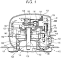
- FIG. 1 is a cross-sectional view of a sealed compressor according to a first exemplary embodiment of the present invention.
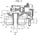
- FIG. 2 is a cross-sectional view showing a main part of the sealed compressor.
- the sealed compressor according to this exemplary embodiment is configured such that compressor body 108 which includes electrically-operated element 104 and compressive element 106 driven by electrically-operated element 104 is disposed in the inside of sealed container 102 formed by drawing a steel plate.
- Compressor body 108 is resiliently supported by suspension springs 120.
- Sealed container 102 is filled with refrigerant gas 122 which is at a pressure substantially equal to a pressure on a low-pressure side of a refrigeration device (not shown in the drawing) and in a relatively low temperature state.
- refrigerant gas 122 is R600a which is a hydrocarbon refrigerant having a low global warming potential.
- a bottom portion in sealed container 102 is filled with lubrication oil 124.
- Compressive element 106 is formed of: shaft 126; cylinder block 128; piston 130; connecting portion 132 and the like.
- Shaft 126 includes: eccentric shaft 134; main shaft 136; and oil supply mechanism 138.
- Oil supply mechanism 138 is formed in a region ranging from a lower end of main shaft 136 which is immersed in oil 124 to an upper end of eccentric shaft 134.
- Cylinder block 128 is an integral body formed of cylinder 142 which forms compression chamber 140 and bearing 144 which rotatably and pivotally supports main shaft 136.
- Main shaft 136 has non-sliding portion 146 on a portion of sliding portion 137 which rotatably slides on an inner peripheral surface of bearing 144, where non-sliding portion 146 is formed by narrowing an outer diameter of main shaft 136.
- Non-sliding portion 146 is formed between an upper end and a lower end of bearing 144. More specifically, considering “a solid contact which occurs between the bearing and the main shaft” and “supply of oil", it is preferable that a size of non-sliding portion 146 in a radial direction formed on the portion of sliding portion 137 of main shaft 136 by narrowing an outer diameter of main shaft 136 be set between 0.2 mm and 1.0 mm (both inclusive).
- non-sliding portion 146 When the size in a radial direction of non-sliding portion 146 is less than 0.2 mm, it is impossible to avoid a solid contact between a deformed portion of the inner peripheral surface of bearing 144 which occurs when stator 150 is fixed to bearing 144 and main shaft 136. When the size in a radial direction of non-sliding portion 146 is larger than 1.0 mm, an oil supply speed at the time of starting the sealed compressor becomes slow so that oil cannot be sufficiently supplied in an upward direction.
- Electrically-operated element 104 is an outer-rotor-type motor formed of: stator 150; and rotor 152 disposed coaxially with stator 150. Rotor 152 is disposed so as to surround a periphery of stator 150.
- rotor 152 permanent magnet 158 is disposed on outer peripheral end portion 156 of disc-like frame 154.
- circular cylindrical rotor shaft hole 160 which is formed on a center of frame 154 is fixedly engaged with an outer periphery of the lower end of main shaft 136 by shrinkage fitting or the like.
- Stator 150 is fixed to outer peripheral portion 162 of bearing 144 at a portion which corresponds to non-sliding portion 146 by press-fitting or the like.
- Length L2 of non-sliding portion 146 formed on main shaft 136 is set longer than length L1 of fixing margin of stator 150.
- the fixing margin of stator 150 is positioned within length L2 of non-sliding portion 146.
- stator 150 When electricity is supplied to electrically-operated element 104, an electric current flows through stator 150 so that a magnetic field is generated, and rotor 152 fixed to main shaft 136 rotates. Due to rotation of rotor 152, shaft 126 rotates. Then, piston 130 moves in a reciprocating manner in cylinder 142 by way of connecting portion 132 rotatably mounted on eccentric shaft 134, and compressive element 106 performs a predetermined compression operation.
- Stator 150 of the outer-rotor-type DC motor is fixed to outer peripheral portion 162 of bearing 144 by press-fitting or the like. Accordingly, the inner peripheral surface of bearing 144 is deformed in an inwardly recessed manner within a range of length L1 of the fixing margin of stator 150.
- non-sliding portion 146 which is formed by narrowing an outer diameter of main shaft 136 is provided to main shaft 136 of the sealed compressor according to this exemplary embodiment.
- stator 150 is fixed to outer peripheral portion 162 of bearing 144 which is a portion which corresponds to non-sliding portion 146. Accordingly, it is possible to avoid solid contact between a deformed portion of the inner peripheral surface of bearing 144 which occurs when stator 150 is fixed to bearing 144 and main shaft 136 and hence, the occurrence of wear can be prevented. Accordingly, the durability of the sealed compressor can be enhanced.
- stator 150 when stator 150 is fixed to outer peripheral portion 162 of bearing 144 by press-fitting or the like, bearing 144 is slightly deformed also outside fixing margin of stator 150.
- length L2 of non-sliding portion 146 is set longer than length L1 of the fixing margin where stator 150 is fixed to outer peripheral portion 162 of bearing 144. Accordingly, also with respect to the deformation which occurs on bearing 144 outside the fixing margin of stator 150, solid contact between main shaft 136 and bearing 144 can be avoided.
- Non-sliding portion 146 is formed by narrowing the outer periphery thereof on a main shaft 136 side and hence, non-sliding portion 146 can be easily formed by lathe machining or the like. Further, deburring or the like after polishing an outer periphery of the main shaft can be also easily performed and hence, the productivity of the sealed compressor can be enhanced.
- Compressive element 106 includes: shaft 126 having main shaft 136 and eccentric shaft 134; and cylinder block 128 having: bearing 144 which pivotally supports main shaft 136 of shaft 126; and cylinder 142.
- Compressive element 106 includes: piston 130 which is movable in cylinder 142 in a reciprocating manner, and connecting portion 132 which connects eccentric shaft 134 and piston 130 to each other.
- Electrically-operated element 104 is formed of an outer-rotor-type motor which includes: stator 150; and rotor 152 which is disposed coaxially with stator 150 so as to surround the outer periphery of stator 150.
- Non-sliding portion 146 is disposed between main shaft 136 and bearing 144, and stator 150 is fixed to outer peripheral portion 162 of bearing 144 which corresponds to non-sliding portion 146.
- stator 150 in fixing stator 150 to outer peripheral portion 162 of bearing 144, even when the inner peripheral surface of bearing 144 at the position where stator 150 is fixed is deformed, non-sliding portion 146 is provided between main shaft 136 and bearing 144 at the deformed portion. Accordingly, a solid contact which occurs between bearing 144 and main shaft 136 is avoided so that the occurrence of wear can be prevented. Accordingly, the durability of the sealed compressor can be enhanced.
- the length of non-sliding portion 146 is longer than the length of the fixing margin where stator 150 is fixed to outer peripheral portion 162 of bearing 144.
- non-sliding portion 146 which is formed by narrowing an outer diameter of main shaft 136 is formed on a portion of sliding portion 137 of main shaft 136 and, further, non-sliding portion 146 is formed between the upper end and the lower end of bearing 144.
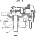
- FIG. 3 is a cross-sectional view showing a main part of a sealed compressor according to a second exemplary embodiment of the present invention.
- parts identical with the parts of the first exemplary embodiment are given the same symbols and the description of those parts is omitted.
- non-sliding portion 246 is formed on a bearing 244 side. That is, non-sliding portion 246 formed by increasing an inner diameter of bearing 244 is formed on a portion of a sliding portion of bearing 244. More specifically, considering “a solid contact which occurs between the bearing and the main shaft” and “supply of oil", it is preferable that a size of non-sliding portion 246 in a radial direction which is formed on the portion of the sliding portion of bearing 244 by increasing an inner diameter of bearing 244 be preferably set between 0.2 mm and 1.0 mm (both inclusive).
- non-sliding portion 246 When the size in a radial direction of non-sliding portion 246 is less than 0.2 mm, it is impossible to avoid a solid contact between a deformed portion of the inner peripheral surface of bearing 244 which occurs when the stator is fixed to bearing 244 and main shaft 236.
- the size in a radial direction of non-sliding portion 246 is larger than 1.0 mm, an oil supply speed at the time of starting the sealed compressor becomes slow so that oil cannot be sufficiently supplied in an upward direction.
- the above-mentioned configuration of this exemplary embodiment even when a sliding area is decreased so that a slide loss is reduced by narrowing an outer shape of main shaft 136, the lowering of rigidity of main shaft 236 can be prevented. Accordingly, the efficiency of the operation of the sealed compressor can be enhanced and, at the same time, the durability of the sealed compressor can be enhanced. Further, the advantageous effects substantially equal to the advantageous effects of the first exemplary embodiment can be acquired.
- stator 150 is fixed to outer peripheral portion 162 of bearing 144 by press-fitting or the like.
- stator 150 is fixed by welding, the inner peripheral surface of bearing 144 is deformed by thermal distortion and hence, substantially the same advantageous effects can be acquired.
- the sealed compressor of this exemplary embodiment includes non-sliding portion 246 which is formed by increasing an inner diameter of bearing 244 on a portion of the sliding portion of bearing 244.
- FIG. 4 is a schematic view showing a refrigeration device according to a third exemplary embodiment of the present invention.
- the sealed compressor described in the first or second exemplary embodiment is mounted in the refrigeration device.
- the refrigeration device is schematically described by taking an article storage device such as a refrigerator as an example.
- the article storage device includes body 302 which is formed of a heat insulating box having an opening on one surface thereof and a door body which opens and closes the opening; partition wall 308; and refrigerant circuit 310.
- Partition wall 308 partitions the inside of body 302 into article storage space 304 and machine compartment 306.
- Refrigerant circuit 310 cools storage space 304.
- Refrigerant circuit 310 is configured such that the sealed compressor described in the first exemplary embodiment which forms compressor 312, heat-radiator 314, pressure reduction device 316, and heat absorbing device 318 are annularly connected to each other by pipes.
- Heat absorbing device 318 is disposed in the inside of storage space 304 equipped with a blower (not shown). Cooling heat of heat absorbing device 318 is stirred by the blower so that cooling heat circulates the inside of storage space 304 as indicated by an arrow. With such an operation, storage space 304 is cooled.
- the sealed compressor described in the first exemplary embodiment is mounted as compressor 312. Accordingly, in compressor 312, stator 150 is fixed to outer peripheral portion 162 of bearing 144 which corresponds to non-sliding portion 146 provided between main shaft 136 and bearing 144 by press-fitting or the like. With such a configuration, even when the inner periphery of bearing 144 is deformed by fixing stator 150, the occurrence of wear which may be caused by a solid contact between the deformed portion of bearing 144 and main shaft 136 can be prevented. Accordingly, the durability of compressor 312 can be enhanced. As a result, the durability of the article storage device can be enhanced.
- the refrigeration device of this exemplary embodiment includes refrigerant circuit 310 which is formed by annularly connecting compressor 312, heat-radiator 314, pressure reduction device 316, and heat absorbing device 318 to each other by pipes, and compressor 312 is the sealed compressor described in the first or second exemplary embodiment. Accordingly, by mounting the sealed compressor whose durability is enhanced in the refrigeration device, the durability of the refrigeration device can be enhanced.
- the sealed compressor and the refrigeration device according to the present invention can enhance the durability of the sealed compressor. Accordingly, the present invention is not limited to household-use electric appliances such as an electric refrigerator or an air conditioner, and is broadly applicable to a refrigeration device for a business-use showcase, a vending machine and the like.
Landscapes
- Engineering & Computer Science (AREA)
- Mechanical Engineering (AREA)
- General Engineering & Computer Science (AREA)
- Physics & Mathematics (AREA)
- Thermal Sciences (AREA)
- Chemical & Material Sciences (AREA)
- Combustion & Propulsion (AREA)
- Compressor (AREA)
Applications Claiming Priority (2)
| Application Number | Priority Date | Filing Date | Title |
|---|---|---|---|
| JP2014095634 | 2014-05-07 | ||
| PCT/JP2015/002183 WO2015170455A1 (ja) | 2014-05-07 | 2015-04-22 | 密閉型圧縮機および冷凍装置 |
Publications (3)
| Publication Number | Publication Date |
|---|---|
| EP3141749A1 true EP3141749A1 (de) | 2017-03-15 |
| EP3141749A4 EP3141749A4 (de) | 2017-05-31 |
| EP3141749B1 EP3141749B1 (de) | 2018-08-01 |
Family
ID=54392315
Family Applications (1)
| Application Number | Title | Priority Date | Filing Date |
|---|---|---|---|
| EP15788770.4A Active EP3141749B1 (de) | 2014-05-07 | 2015-04-22 | Hermetischer verdichter und kühlvorrichtung |
Country Status (5)
| Country | Link |
|---|---|
| US (1) | US10001116B2 (de) |
| EP (1) | EP3141749B1 (de) |
| JP (1) | JP6585588B2 (de) |
| CN (1) | CN106030106A (de) |
| WO (1) | WO2015170455A1 (de) |
Families Citing this family (7)
| Publication number | Priority date | Publication date | Assignee | Title |
|---|---|---|---|---|
| DE112014004018T5 (de) * | 2013-09-03 | 2016-07-14 | Panasonic Intellectual Property Management Co., Ltd. | Abgedichteter Kompressor und damit ausgestattete Gefriervorrichtung oder Kühlschrank |
| CN107339219A (zh) * | 2017-07-28 | 2017-11-10 | 安徽美芝制冷设备有限公司 | 用于往复式压缩机的机架及其加工方法 |
| JP7083101B2 (ja) * | 2017-11-24 | 2022-06-10 | Tianma Japan株式会社 | 表示装置 |
| WO2020045485A1 (ja) * | 2018-08-30 | 2020-03-05 | パナソニック アプライアンシズ リフリジレーション デヴァイシズ シンガポール | 圧縮機およびそれを用いた冷凍・冷蔵装置、並びに、圧縮機の製造方法 |
| KR102150445B1 (ko) | 2018-10-22 | 2020-09-01 | 엘지전자 주식회사 | 외전형 모터에 대응되는 실린더 블록을 포함하는 압축기 |
| KR102319349B1 (ko) * | 2020-01-09 | 2021-10-28 | 엘지전자 주식회사 | 모터 조립체 및 이를 포함하는 왕복동식 압축기 |
| US20240426286A1 (en) * | 2023-06-22 | 2024-12-26 | Samsung Electronics Co., Ltd. | Reciprocating compressor using outer rotor motor |
Family Cites Families (15)
| Publication number | Priority date | Publication date | Assignee | Title |
|---|---|---|---|---|
| DE3422743A1 (de) | 1984-06-19 | 1985-12-19 | Ebm Elektrobau Mulfingen Gmbh & Co, 7119 Mulfingen | Aussenlaeufermotor mit angeschraubtem motorflansch |
| JP3007570U (ja) * | 1994-04-06 | 1995-02-21 | 株式会社シコー技研 | マイクロモ−タ |
| JP2005344600A (ja) * | 2004-06-02 | 2005-12-15 | Toshiba Kyaria Kk | 密閉型圧縮機 |
| JP2006226273A (ja) * | 2005-01-18 | 2006-08-31 | Toshiba Kyaria Kk | 密閉型圧縮機および冷凍サイクル装置 |
| EP1816727A3 (de) | 2006-02-03 | 2011-04-06 | ebm-papst St. Georgen GmbH & Co. KG | Elektromotor |
| CN200990537Y (zh) | 2006-12-18 | 2007-12-12 | 中山大洋电机股份有限公司 | 一种外转子电机轴与定子的减振连接装置 |
| JP4946625B2 (ja) | 2007-05-21 | 2012-06-06 | 日本電産株式会社 | モータ |
| DE102008000124A1 (de) * | 2008-01-22 | 2009-07-30 | Visteon Global Technologies, Inc., Van Buren Township | Kompressor, insbesondere elektromotorisch angetriebener Kompressor |
| CN102272453B (zh) * | 2009-01-07 | 2015-06-17 | Lg电子株式会社 | 往复式压缩机及具有该往复式压缩机的制冷装置 |
| DE102010051300A1 (de) * | 2010-11-12 | 2012-05-16 | Secop Gmbh | Kältemittelkompressor |
| DE102010051262A1 (de) * | 2010-11-12 | 2012-05-31 | Secop Gmbh | Kältemittelverdichter |
| DE102010051266A1 (de) * | 2010-11-12 | 2012-05-16 | Secop Gmbh | Kältemittelverdichter |
| BRPI1100652B1 (pt) * | 2011-01-13 | 2021-08-10 | Embraco Indústria De Compressores E Soluções Em Refrigeração Ltda | Arranjo de mancalização para um compressor alternativo de refrigeração |
| JP5712882B2 (ja) | 2011-09-28 | 2015-05-07 | 株式会社豊田自動織機 | 電動圧縮機用の電動モータ |
| CN102364100B (zh) * | 2011-11-11 | 2015-01-07 | 黄石东贝电器股份有限公司 | 一种制冷压缩机曲轴轴向止推轴承支承结构 |
-
2015
- 2015-04-22 WO PCT/JP2015/002183 patent/WO2015170455A1/ja not_active Ceased
- 2015-04-22 EP EP15788770.4A patent/EP3141749B1/de active Active
- 2015-04-22 JP JP2016517808A patent/JP6585588B2/ja active Active
- 2015-04-22 US US15/117,721 patent/US10001116B2/en active Active
- 2015-04-22 CN CN201580009749.5A patent/CN106030106A/zh active Pending
Also Published As
| Publication number | Publication date |
|---|---|
| CN106030106A (zh) | 2016-10-12 |
| JPWO2015170455A1 (ja) | 2017-04-20 |
| EP3141749A4 (de) | 2017-05-31 |
| EP3141749B1 (de) | 2018-08-01 |
| JP6585588B2 (ja) | 2019-10-02 |
| US20170009755A1 (en) | 2017-01-12 |
| WO2015170455A1 (ja) | 2015-11-12 |
| US10001116B2 (en) | 2018-06-19 |
Similar Documents
| Publication | Publication Date | Title |
|---|---|---|
| EP3141749B1 (de) | Hermetischer verdichter und kühlvorrichtung | |
| EP3168474A1 (de) | Hermetischer verdichter und kühlvorrichtung damit | |
| KR101660581B1 (ko) | 스크롤 타입 압축기의 자전 방지 링의 제조 방법 및 스크롤 타입 압축기의 자전 방지 기구 | |
| KR101110225B1 (ko) | 스크롤압축기 | |
| US10830222B2 (en) | Refrigeration compressor having an outer-rotor type motor with the stator fixed to a member fixed to a cylinder block | |
| JP2016006303A (ja) | 密閉型圧縮機および冷凍装置 | |
| US11236740B2 (en) | Sealed compressor and freezer device or refrigerator equipped with same | |
| JP6001410B2 (ja) | 密閉型電動圧縮機及びこれを用いた冷凍空調装置 | |
| JP6648342B2 (ja) | 密閉型冷媒圧縮機および冷凍装置 | |
| JP2020112032A (ja) | 密閉型圧縮機およびそれを用いた冷凍装置 | |
| EP3495659B1 (de) | Verdichter | |
| JP6270080B1 (ja) | 密閉型ロータリ圧縮機 | |
| JP6480142B2 (ja) | 密閉型圧縮機、前記密閉型圧縮機を備える冷凍装置、及び前記密閉型圧縮機を備える冷蔵庫 | |
| JP2017145787A (ja) | 密閉型圧縮機およびそれを用いた冷凍装置 | |
| CN104114864B (zh) | 密闭型压缩机和具备其的制冷装置 | |
| JP2020167746A (ja) | 電動機及びそれを用いた密閉型電動圧縮機、冷凍装置 | |
| JP6568758B2 (ja) | 密閉型圧縮機及び冷凍サイクル装置 | |
| WO2015078532A1 (en) | Reciprocating compressor with reduced size and improved shape for use in a refrigeration appliance | |
| CN108368849A (zh) | 压缩机以及制冷循环装置 | |
| JP2020094559A (ja) | 密閉型圧縮機及び冷凍装置 | |
| JP2020094558A (ja) | 密閉型圧縮機及び冷凍装置 | |
| WO2020085427A1 (ja) | 密閉型圧縮機及び冷凍装置 | |
| JP2021095858A (ja) | 圧縮機、冷凍冷蔵機器および空気調和装置 |
Legal Events
| Date | Code | Title | Description |
|---|---|---|---|
| STAA | Information on the status of an ep patent application or granted ep patent |
Free format text: STATUS: THE INTERNATIONAL PUBLICATION HAS BEEN MADE |
|
| PUAI | Public reference made under article 153(3) epc to a published international application that has entered the european phase |
Free format text: ORIGINAL CODE: 0009012 |
|
| STAA | Information on the status of an ep patent application or granted ep patent |
Free format text: STATUS: REQUEST FOR EXAMINATION WAS MADE |
|
| 17P | Request for examination filed |
Effective date: 20161207 |
|
| AK | Designated contracting states |
Kind code of ref document: A1 Designated state(s): AL AT BE BG CH CY CZ DE DK EE ES FI FR GB GR HR HU IE IS IT LI LT LU LV MC MK MT NL NO PL PT RO RS SE SI SK SM TR |
|
| AX | Request for extension of the european patent |
Extension state: BA ME |
|
| RAP1 | Party data changed (applicant data changed or rights of an application transferred) |
Owner name: PANASONIC CORPORATION |
|
| A4 | Supplementary search report drawn up and despatched |
Effective date: 20170503 |
|
| RIC1 | Information provided on ipc code assigned before grant |
Ipc: H02K 1/18 20060101ALI20170425BHEP Ipc: F04B 39/00 20060101AFI20170425BHEP |
|
| DAV | Request for validation of the european patent (deleted) | ||
| DAX | Request for extension of the european patent (deleted) | ||
| GRAP | Despatch of communication of intention to grant a patent |
Free format text: ORIGINAL CODE: EPIDOSNIGR1 |
|
| STAA | Information on the status of an ep patent application or granted ep patent |
Free format text: STATUS: GRANT OF PATENT IS INTENDED |
|
| INTG | Intention to grant announced |
Effective date: 20180209 |
|
| GRAS | Grant fee paid |
Free format text: ORIGINAL CODE: EPIDOSNIGR3 |
|
| GRAA | (expected) grant |
Free format text: ORIGINAL CODE: 0009210 |
|
| STAA | Information on the status of an ep patent application or granted ep patent |
Free format text: STATUS: THE PATENT HAS BEEN GRANTED |
|
| AK | Designated contracting states |
Kind code of ref document: B1 Designated state(s): AL AT BE BG CH CY CZ DE DK EE ES FI FR GB GR HR HU IE IS IT LI LT LU LV MC MK MT NL NO PL PT RO RS SE SI SK SM TR |
|
| REG | Reference to a national code |
Ref country code: GB Ref legal event code: FG4D |
|
| REG | Reference to a national code |
Ref country code: CH Ref legal event code: EP Ref country code: AT Ref legal event code: REF Ref document number: 1024624 Country of ref document: AT Kind code of ref document: T Effective date: 20180815 |
|
| REG | Reference to a national code |
Ref country code: IE Ref legal event code: FG4D |
|
| REG | Reference to a national code |
Ref country code: DE Ref legal event code: R096 Ref document number: 602015014428 Country of ref document: DE |
|
| REG | Reference to a national code |
Ref country code: DE Ref legal event code: R081 Ref document number: 602015014428 Country of ref document: DE Owner name: PANASONIC APPLIANCES REFRIGERATION DEVICES SIN, SG Free format text: FORMER OWNER: PANASONIC CORPORATION, KADOMA-SHI, OSAKA, JP |
|
| RAP2 | Party data changed (patent owner data changed or rights of a patent transferred) |
Owner name: PANASONIC APPLIANCES REFRIGERATION DEVICES SINGAPO |
|
| REG | Reference to a national code |
Ref country code: NL Ref legal event code: MP Effective date: 20180801 |
|
| REG | Reference to a national code |
Ref country code: LT Ref legal event code: MG4D |
|
| REG | Reference to a national code |
Ref country code: AT Ref legal event code: MK05 Ref document number: 1024624 Country of ref document: AT Kind code of ref document: T Effective date: 20180801 |
|
| PG25 | Lapsed in a contracting state [announced via postgrant information from national office to epo] |
Ref country code: FI Free format text: LAPSE BECAUSE OF FAILURE TO SUBMIT A TRANSLATION OF THE DESCRIPTION OR TO PAY THE FEE WITHIN THE PRESCRIBED TIME-LIMIT Effective date: 20180801 Ref country code: NL Free format text: LAPSE BECAUSE OF FAILURE TO SUBMIT A TRANSLATION OF THE DESCRIPTION OR TO PAY THE FEE WITHIN THE PRESCRIBED TIME-LIMIT Effective date: 20180801 Ref country code: BG Free format text: LAPSE BECAUSE OF FAILURE TO SUBMIT A TRANSLATION OF THE DESCRIPTION OR TO PAY THE FEE WITHIN THE PRESCRIBED TIME-LIMIT Effective date: 20181101 Ref country code: PL Free format text: LAPSE BECAUSE OF FAILURE TO SUBMIT A TRANSLATION OF THE DESCRIPTION OR TO PAY THE FEE WITHIN THE PRESCRIBED TIME-LIMIT Effective date: 20180801 Ref country code: LT Free format text: LAPSE BECAUSE OF FAILURE TO SUBMIT A TRANSLATION OF THE DESCRIPTION OR TO PAY THE FEE WITHIN THE PRESCRIBED TIME-LIMIT Effective date: 20180801 Ref country code: SE Free format text: LAPSE BECAUSE OF FAILURE TO SUBMIT A TRANSLATION OF THE DESCRIPTION OR TO PAY THE FEE WITHIN THE PRESCRIBED TIME-LIMIT Effective date: 20180801 Ref country code: AT Free format text: LAPSE BECAUSE OF FAILURE TO SUBMIT A TRANSLATION OF THE DESCRIPTION OR TO PAY THE FEE WITHIN THE PRESCRIBED TIME-LIMIT Effective date: 20180801 Ref country code: NO Free format text: LAPSE BECAUSE OF FAILURE TO SUBMIT A TRANSLATION OF THE DESCRIPTION OR TO PAY THE FEE WITHIN THE PRESCRIBED TIME-LIMIT Effective date: 20181101 Ref country code: GR Free format text: LAPSE BECAUSE OF FAILURE TO SUBMIT A TRANSLATION OF THE DESCRIPTION OR TO PAY THE FEE WITHIN THE PRESCRIBED TIME-LIMIT Effective date: 20181102 Ref country code: IS Free format text: LAPSE BECAUSE OF FAILURE TO SUBMIT A TRANSLATION OF THE DESCRIPTION OR TO PAY THE FEE WITHIN THE PRESCRIBED TIME-LIMIT Effective date: 20181201 Ref country code: RS Free format text: LAPSE BECAUSE OF FAILURE TO SUBMIT A TRANSLATION OF THE DESCRIPTION OR TO PAY THE FEE WITHIN THE PRESCRIBED TIME-LIMIT Effective date: 20180801 |
|
| PG25 | Lapsed in a contracting state [announced via postgrant information from national office to epo] |
Ref country code: HR Free format text: LAPSE BECAUSE OF FAILURE TO SUBMIT A TRANSLATION OF THE DESCRIPTION OR TO PAY THE FEE WITHIN THE PRESCRIBED TIME-LIMIT Effective date: 20180801 Ref country code: LV Free format text: LAPSE BECAUSE OF FAILURE TO SUBMIT A TRANSLATION OF THE DESCRIPTION OR TO PAY THE FEE WITHIN THE PRESCRIBED TIME-LIMIT Effective date: 20180801 Ref country code: AL Free format text: LAPSE BECAUSE OF FAILURE TO SUBMIT A TRANSLATION OF THE DESCRIPTION OR TO PAY THE FEE WITHIN THE PRESCRIBED TIME-LIMIT Effective date: 20180801 |
|
| PG25 | Lapsed in a contracting state [announced via postgrant information from national office to epo] |
Ref country code: CZ Free format text: LAPSE BECAUSE OF FAILURE TO SUBMIT A TRANSLATION OF THE DESCRIPTION OR TO PAY THE FEE WITHIN THE PRESCRIBED TIME-LIMIT Effective date: 20180801 Ref country code: RO Free format text: LAPSE BECAUSE OF FAILURE TO SUBMIT A TRANSLATION OF THE DESCRIPTION OR TO PAY THE FEE WITHIN THE PRESCRIBED TIME-LIMIT Effective date: 20180801 Ref country code: IT Free format text: LAPSE BECAUSE OF FAILURE TO SUBMIT A TRANSLATION OF THE DESCRIPTION OR TO PAY THE FEE WITHIN THE PRESCRIBED TIME-LIMIT Effective date: 20180801 Ref country code: EE Free format text: LAPSE BECAUSE OF FAILURE TO SUBMIT A TRANSLATION OF THE DESCRIPTION OR TO PAY THE FEE WITHIN THE PRESCRIBED TIME-LIMIT Effective date: 20180801 Ref country code: ES Free format text: LAPSE BECAUSE OF FAILURE TO SUBMIT A TRANSLATION OF THE DESCRIPTION OR TO PAY THE FEE WITHIN THE PRESCRIBED TIME-LIMIT Effective date: 20180801 |
|
| REG | Reference to a national code |
Ref country code: DE Ref legal event code: R097 Ref document number: 602015014428 Country of ref document: DE |
|
| PG25 | Lapsed in a contracting state [announced via postgrant information from national office to epo] |
Ref country code: SK Free format text: LAPSE BECAUSE OF FAILURE TO SUBMIT A TRANSLATION OF THE DESCRIPTION OR TO PAY THE FEE WITHIN THE PRESCRIBED TIME-LIMIT Effective date: 20180801 Ref country code: SM Free format text: LAPSE BECAUSE OF FAILURE TO SUBMIT A TRANSLATION OF THE DESCRIPTION OR TO PAY THE FEE WITHIN THE PRESCRIBED TIME-LIMIT Effective date: 20180801 Ref country code: DK Free format text: LAPSE BECAUSE OF FAILURE TO SUBMIT A TRANSLATION OF THE DESCRIPTION OR TO PAY THE FEE WITHIN THE PRESCRIBED TIME-LIMIT Effective date: 20180801 |
|
| PLBE | No opposition filed within time limit |
Free format text: ORIGINAL CODE: 0009261 |
|
| STAA | Information on the status of an ep patent application or granted ep patent |
Free format text: STATUS: NO OPPOSITION FILED WITHIN TIME LIMIT |
|
| 26N | No opposition filed |
Effective date: 20190503 |
|
| PG25 | Lapsed in a contracting state [announced via postgrant information from national office to epo] |
Ref country code: SI Free format text: LAPSE BECAUSE OF FAILURE TO SUBMIT A TRANSLATION OF THE DESCRIPTION OR TO PAY THE FEE WITHIN THE PRESCRIBED TIME-LIMIT Effective date: 20180801 |
|
| REG | Reference to a national code |
Ref country code: CH Ref legal event code: PL |
|
| REG | Reference to a national code |
Ref country code: BE Ref legal event code: MM Effective date: 20190430 |
|
| GBPC | Gb: european patent ceased through non-payment of renewal fee |
Effective date: 20190422 |
|
| PG25 | Lapsed in a contracting state [announced via postgrant information from national office to epo] |
Ref country code: MC Free format text: LAPSE BECAUSE OF FAILURE TO SUBMIT A TRANSLATION OF THE DESCRIPTION OR TO PAY THE FEE WITHIN THE PRESCRIBED TIME-LIMIT Effective date: 20180801 Ref country code: LU Free format text: LAPSE BECAUSE OF NON-PAYMENT OF DUE FEES Effective date: 20190422 |
|
| PG25 | Lapsed in a contracting state [announced via postgrant information from national office to epo] |
Ref country code: GB Free format text: LAPSE BECAUSE OF NON-PAYMENT OF DUE FEES Effective date: 20190422 Ref country code: CH Free format text: LAPSE BECAUSE OF NON-PAYMENT OF DUE FEES Effective date: 20190430 Ref country code: LI Free format text: LAPSE BECAUSE OF NON-PAYMENT OF DUE FEES Effective date: 20190430 |
|
| PG25 | Lapsed in a contracting state [announced via postgrant information from national office to epo] |
Ref country code: FR Free format text: LAPSE BECAUSE OF NON-PAYMENT OF DUE FEES Effective date: 20190430 Ref country code: BE Free format text: LAPSE BECAUSE OF NON-PAYMENT OF DUE FEES Effective date: 20190430 |
|
| PG25 | Lapsed in a contracting state [announced via postgrant information from national office to epo] |
Ref country code: TR Free format text: LAPSE BECAUSE OF FAILURE TO SUBMIT A TRANSLATION OF THE DESCRIPTION OR TO PAY THE FEE WITHIN THE PRESCRIBED TIME-LIMIT Effective date: 20180801 |
|
| PG25 | Lapsed in a contracting state [announced via postgrant information from national office to epo] |
Ref country code: IE Free format text: LAPSE BECAUSE OF NON-PAYMENT OF DUE FEES Effective date: 20190422 |
|
| PG25 | Lapsed in a contracting state [announced via postgrant information from national office to epo] |
Ref country code: PT Free format text: LAPSE BECAUSE OF FAILURE TO SUBMIT A TRANSLATION OF THE DESCRIPTION OR TO PAY THE FEE WITHIN THE PRESCRIBED TIME-LIMIT Effective date: 20181201 |
|
| PG25 | Lapsed in a contracting state [announced via postgrant information from national office to epo] |
Ref country code: CY Free format text: LAPSE BECAUSE OF FAILURE TO SUBMIT A TRANSLATION OF THE DESCRIPTION OR TO PAY THE FEE WITHIN THE PRESCRIBED TIME-LIMIT Effective date: 20180801 |
|
| PG25 | Lapsed in a contracting state [announced via postgrant information from national office to epo] |
Ref country code: MT Free format text: LAPSE BECAUSE OF FAILURE TO SUBMIT A TRANSLATION OF THE DESCRIPTION OR TO PAY THE FEE WITHIN THE PRESCRIBED TIME-LIMIT Effective date: 20180801 Ref country code: HU Free format text: LAPSE BECAUSE OF FAILURE TO SUBMIT A TRANSLATION OF THE DESCRIPTION OR TO PAY THE FEE WITHIN THE PRESCRIBED TIME-LIMIT; INVALID AB INITIO Effective date: 20150422 |
|
| PG25 | Lapsed in a contracting state [announced via postgrant information from national office to epo] |
Ref country code: MK Free format text: LAPSE BECAUSE OF FAILURE TO SUBMIT A TRANSLATION OF THE DESCRIPTION OR TO PAY THE FEE WITHIN THE PRESCRIBED TIME-LIMIT Effective date: 20180801 |
|
| REG | Reference to a national code |
Ref country code: DE Ref legal event code: R081 Ref document number: 602015014428 Country of ref document: DE Owner name: PANASONIC CORPORATION, KADOMA-SHI, JP Free format text: FORMER OWNER: PANASONIC APPLIANCES REFRIGERATION DEVICES SINGAPORE, SINGAPORE, SG |
|
| PGFP | Annual fee paid to national office [announced via postgrant information from national office to epo] |
Ref country code: DE Payment date: 20250422 Year of fee payment: 11 |