EP3141765A1 - Einfache verrieglungsvorrichtung - Google Patents
Einfache verrieglungsvorrichtung Download PDFInfo
- Publication number
- EP3141765A1 EP3141765A1 EP14891430.2A EP14891430A EP3141765A1 EP 3141765 A1 EP3141765 A1 EP 3141765A1 EP 14891430 A EP14891430 A EP 14891430A EP 3141765 A1 EP3141765 A1 EP 3141765A1
- Authority
- EP
- European Patent Office
- Prior art keywords
- locking
- connecting component
- piece
- tongue piece
- base
- Prior art date
- Legal status (The legal status is an assumption and is not a legal conclusion. Google has not performed a legal analysis and makes no representation as to the accuracy of the status listed.)
- Granted
Links
Images




Classifications
-
- F—MECHANICAL ENGINEERING; LIGHTING; HEATING; WEAPONS; BLASTING
- F16—ENGINEERING ELEMENTS AND UNITS; GENERAL MEASURES FOR PRODUCING AND MAINTAINING EFFECTIVE FUNCTIONING OF MACHINES OR INSTALLATIONS; THERMAL INSULATION IN GENERAL
- F16B—DEVICES FOR FASTENING OR SECURING CONSTRUCTIONAL ELEMENTS OR MACHINE PARTS TOGETHER, e.g. NAILS, BOLTS, CIRCLIPS, CLAMPS, CLIPS OR WEDGES; JOINTS OR JOINTING
- F16B1/00—Devices for securing together, or preventing relative movement between, constructional elements or machine parts
- F16B1/02—Means for securing elements of mechanisms after operation
- F16B1/04—Means for securing elements of mechanisms after operation disengaged by movement of the actuating member of the element
-
- E—FIXED CONSTRUCTIONS
- E05—LOCKS; KEYS; WINDOW OR DOOR FITTINGS; SAFES
- E05C—BOLTS OR FASTENING DEVICES FOR WINGS, SPECIALLY FOR DOORS OR WINDOWS
- E05C1/00—Fastening devices with bolts moving rectilinearly
- E05C1/002—Fastening devices with bolts moving rectilinearly perpendicular to the surface on which the fastener is mounted
-
- E—FIXED CONSTRUCTIONS
- E05—LOCKS; KEYS; WINDOW OR DOOR FITTINGS; SAFES
- E05C—BOLTS OR FASTENING DEVICES FOR WINGS, SPECIALLY FOR DOORS OR WINDOWS
- E05C1/00—Fastening devices with bolts moving rectilinearly
- E05C1/004—Fastening devices with bolts moving rectilinearly parallel to the surface on which the fastener is mounted
-
- E—FIXED CONSTRUCTIONS
- E05—LOCKS; KEYS; WINDOW OR DOOR FITTINGS; SAFES
- E05C—BOLTS OR FASTENING DEVICES FOR WINGS, SPECIALLY FOR DOORS OR WINDOWS
- E05C9/00—Arrangements of simultaneously actuated bolts or other securing devices at well-separated positions on the same wing
- E05C9/002—Arrangements of simultaneously actuated bolts or other securing devices at well-separated positions on the same wing with arrangements allowing the wing to be slam-shut, e.g. by securing elements with latching action
Definitions
- the present application relates to the field of mechanical apparatus, and particularly to a simple locking device.
- the movable device for locking the movable device, generally, multiple locking components (such as a handle catch, a rotary lock or a movable pin lock), each having a single capability, are adopted to lock the movable device.
- multiple locking components such as a handle catch, a rotary lock or a movable pin lock
- this kind of locking device can only achieve mechanical unlocking and locking by a single action, or achieve one function by multiple mechanisms and/or multiple actions, and cannot perform actions in multiple states by a single mechanism to achieve the locking function in various states, therefore, the operation is troublesome.
- a simple locking device is provided according to the present application, which can perform actions in multiple states by a single mechanism to lock up a movable device, thereby making the operation to be easier and more convenient and facilitating improving the user experience.
- a simple locking device includes a locking bracket, a locking tongue piece, a tension spring, a tension side wall, a base, at least two guide shafts, a connecting component 7a and a connecting component 7b.
- the locking bracket includes a locking piece, at least two guide holes and a retaining piece.
- the tension side wall is fixed to the base.
- the at least two guide shafts respectively pass through the at least two guide holes to mount the locking bracket to the base, and the locking bracket configured to be guided by the guide holes to move.
- the tension spring has one end fixed to the tension side wall, and another end fixedly connected to the locking tongue piece.
- the locking tongue piece is movably connected to the locking piece, the locking tongue piece is provided with a front-end extending portion, and the locking piece is provided with an inclined protruding portion.
- the connecting component 7a is provided with a groove position configured to cooperate with the inclined protruding portion of the locking piece, and an extending portion configured to cooperate with the front-end extending portion of the locking tongue piece.
- the connecting component 7b is provided with a retaining hole configured to cooperate with the retaining piece.
- the locking tongue piece further includes a spring hooking position, and the spring hooking position is arranged at a side surface of the locking tongue piece, and is fixedly connected to the tension spring; and the locking bracket further includes a handle position, and the handle position is arranged at an end of the locking bracket close to the retaining piece, and is configured to provide a force applying point for pulling the locking bracket.
- the connecting component 7a and the connecting component 7b are configured to be mounted to a same movable device; and/or, the connecting component 7a and the connecting component 7b are configured to be arranged on a same movable device.
- the connecting component 7a and the connecting component 7b are respectively configured to be located on the movable device symmetrically.
- the simple locking device further includes a pin shaft, and the pin shaft is configured to allow the locking tongue piece to be movably connected to the locking piece.
- the extending portion of the connecting component 7a presses the front end protrusion of the locking tongue piece downwards and abuts against the front end protrusion of the locking tongue piece, and the retaining piece is retained into the retaining hole of the connecting component 7b.
- the tension spring is in a tensioned state, and the locking bracket is guided by the guide holes to move by a certain distance in a direction away from the tension side wall, and the inclined protruding portion of the locking piece is disengaged from the groove position of the connecting component 7a, and the retaining piece is disengaged from the retaining hole of the connecting component 7b.
- the guide holes have the same guide directions.
- the guide shafts are bolts; or, the guide shafts are protruding shafts arranged on the base.
- the tension side wall is welded to the base; or, the tension side wall is fixed to the base by a bolt.
- the present application has the following advantages.
- a simple locking device includes a locking bracket, a locking tongue piece, a tension spring, a tension side wall, a base, at least two guide shafts, and a connecting component 7a and a connecting component 7b.
- the locking bracket includes a locking piece, at least two guide holes and a retaining piece.
- the tension side wall is fixed to the base.
- the at least two guide shafts respectively pass through the at least two guide holes, to mount the locking bracket to the base, and the movement of the locking bracket is guided by the guide holes.
- the tension spring has one end fixed to the tension side wall, and another end fixedly connect to the locking tongue piece.
- the locking tongue piece is movably connected to the locking piece.
- the locking tongue piece is provided with a front-end extending portion at its front end, the locking piece is provided with an inclined protruding portion, and the connecting component 7a is provided with a groove position configured to cooperate with the inclined protruding portion of the locking piece, and an extending portion configured to cooperate with the front-end extending portion of the locking tongue piece.
- the connecting component 7b is provided with a retaining hole configured to cooperate with the retaining piece.
- the locking bracket, the locking tongue piece, the tension spring, the tension side wall, the base, the at least two guide shafts, the connecting component 7a and the connecting component 7b constitute a locking mechanism, which may perform actions in multiple states by a single mechanism, and no longer just performs the mechanical unlocking and locking by a single action, but can lock the movable device connected to the connecting component 7a and the connecting component7b in different states, thus, the operation becomes easier and more convenient, and the improvement of the user experience is facilitated.
- a simple locking device is provided according to an embodiment of the present application, which is configured to perform actions in multiple states by a single mechanism to lock the movable device, thereby making the operation to be easier and more convenient, and facilitating improving the user experience.
- an embodiment of a simple locking device includes a locking bracket 1, a locking tongue piece 2, a tension spring 3, a tension side wall 4, a base 5, at least two guide shafts 6, a connecting component 7a and a connecting component 7b, as shown in Figure 1 .
- Figure 2a is a top view of the locking bracket 1
- Figure 2b is a front view of the locking bracket 1.
- the locking bracket 1 includes a locking piece 11, at least two guide holes 12, and a retaining piece 13.
- the guide holes 12 have the same guide directions.
- the structure of the locking piece 11 may be referred to Figure 2 .
- the locking piece 11 may be a hard sheet perpendicular to a plane where the guide holes 12 are located, and a front end of the locking piece 11 is provided with an inclined protruding portion 111, and the inclined protruding portion 111 may cooperate with a groove position 71 of the connecting component 7a to achieve the locking function.
- the specific operation process is described hereinafter.
- the locking piece 11 is arranged at a left end of the locking bracket 1
- the retaining piece 13 is arranged at a right end of the locking bracket 1
- the retaining piece 13 can be retained in a retaining hole 73 in the connecting component 7b, to lock the connecting component 7b.
- the locking bracket 1 may further be provided with a handle position 14, and the handle position 14 is arranged at an end, close to the retaining piece 13, of the locking bracket 1, and is configured to provide a force applying point for pulling the locking bracket 1.
- Figure 3 is a schematic view showing the structure of the simple locking device according to the embodiment of the present application, with a movable device being locked to the simple locking device, wherein, Figure 3a is a top view of the simple locking device, Figure 3b is a right view of the simple locking device, Figure 3c is a front view of the simple locking device, and Figure 3d is a left view of the simple locking device.
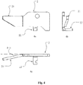
- Figure 4a is a front view of the locking tongue piece 2
- Figure 4b is a side view of the locking tongue piece 2
- Figure 4c is a top view of the locking tongue piece 2.
- the locking tongue piece 2 may be a hard sheet, and the locking tongue piece 2 is provided with a front-end extending portion 21 at its front end.
- the front-end extending portion 21 of the locking tongue piece 2 is arranged at a small angle ⁇ with respect to a main body of the locking tongue piece 2, thus, after the locking tongue piece 2 and the locking piece 11 are movably connected via a pin shaft 8, an angle ⁇ is also formed between the front-end extending portion 21 and the inclined protruding portion 111, and thus the front-end extending portion 21 and the inclined protruding portion 111 will not interfere with each other when the front-end extending portion 21 and the inclined protruding portion 111 respectively engage with the connecting component 7a, and the specific operation process will be described hereinafter.
- the locking tongue piece 2 may further include a spring hooking position 22, and the spring hooking position 22 is arranged at a side surface of the locking tongue piece 2, and is fixedly connected to the tension spring 3.
- Figure 5a is a top view of the base 5
- Figure 5b is a front view of the base 5.
- the base 5 may be a flat plate, and the material of the base 5 and the position for fixing the base 5 may be adjusted according to practical situations, which are not limited specifically.
- the base 5 is provided with at least two mounting holes or at least two protruding shafts 51.
- the guide shafts 6 are embodied as the protruding shafts 51
- at least two protruding shafts 51 are provided on the base 5; and in the case that the guide shafts 6 are embodied as bolts, at least two mounting holes are provided in the base 5.
- the base 5 may be further provided with two mounting holes 52, and in the case that the tension side wall 4 is fixed to the base 5 via screws, the mounting holes 52 are configured to cooperate with the screws to fix the tension side wall 4 to the base 5.
- Figure 5 shows a front view and a top view of the base 5 in the case that the guide shafts 6 are embodied as the protruding shafts 51.
- the connecting component 7a is provided with the groove position 71 and the extending portion 72.
- the groove position 71 is configured to cooperate with the inclined protruding portion 111 of the locking piece 11, and the extending portion 72 is configured to cooperate with the front-end extending portion 21 of the locking tongue piece 2.
- the movement of the connecting component 7a in the vertical direction in Figure 1 may be locked, and the front-end extending portion 21 of the locking tongue piece 2 may be pressed against the bottom of the extending portion 72, as shown in the partially enlarged view in Figure 7 .
- the connecting component 7a and the connecting component 7b may be mounted to the same movable device, and/or, the connecting component 7a and the connecting component 7b may be arranged in the same movable device.
- the connecting component 7a is arranged at a left side of the movable device
- the connecting component 7b is arranged at a right side of the movable device.
- the connecting component 7a and the connecting component 7b may be located on the movable device symmetrically according to the principle of structural mechanics.
- the connection relationship between components of the simple locking device according to this embodiment is described as follows.
- the tension side wall 4 is fixed to the base 5.
- the two guide shafts 6 respectively pass through the two guide holes 12 to mount the locking bracket to the base 5, and the locking bracket 1 is guided by the guide holes 12 to move.
- the tension spring 3 has one end fixed to the tension side wall 4, and another end fixedly connected to the locking bracket 1.
- the locking tongue piece 2 is movably connected to the locking piece 11, and the locking tongue piece 2 is provided with a front-end extending portion 21, and the locking piece 11 is provided with an inclined protruding portion 111.
- the connecting component 7b is provided with a retaining hole 73 configured to cooperate with the retaining piece 13.
- the retaining piece 13 is a wedge-shaped hook.
- the locking bracket 1 may be provided with several retaining pieces 13, and also, the connecting component 7b may be provided with several retaining holes 73 for cooperating with the several retaining pieces 13 respectively.
- the tension side wall 4 is welded to the base 5, or the tension side wall 4 is fixed to the base 5 by a bolt.
- the tension spring 3 is in a tensioned state, and the locking bracket is guided by the guide holes 12 to move by a certain distance in a direction away from the tension side wall 4, the inclined protruding portion 111 of the locking piece 11 is disengaged from the groove position 71 of the connecting component 7a, and the retaining piece 13 is disengaged from the retaining hole 73 of the connecting component 7b.
- the simple locking device has three working states, including an initial state, a locked state, and an unlocked state.
- the tension spring 3 is in an initial state (the tension spring 3 may be in a loose state, and may also be tensioned to a certain extent), and at this time, the locking bracket 1 is at a leftmost end in a movable range under the position-limiting effect of the guide holes 12, and each of the guide shafts 6 is at a rightmost position in the respective guide hole 12.
- the locking bracket 1 is guided by the guide holes 12 to move rightward by a certain distance, at this time, the groove position 71 of the connecting component 7a is just disposed down to the position corresponding to the inclined protruding portion 111, and the retaining hole 73 of the connecting component 7b is just disposed down to a clamping position for engaging with the retaining piece 13.
- the locking bracket 1 moves back leftward by a small distance, to allow the inclined protruding portion 111 to be clamped into the groove position 71, and allow the retaining piece 13 to be clamped into the retaining hole 73 of the connecting component 7b.
- the front-end extending portion 21 of the locking tongue piece 2 continues to be pressed downwards by the extending portion 72 of the connecting component 7a, till the movable device is thoroughly locked into the simple locking device, and at this time, the simple locking device enters into the locked state.
- the locking bracket 1 moves leftward under the action of the restoring force of the tension spring 3, however at this time, the front-end extending portion 21 of the locking tongue piece 2 just abuts against the side surface of the extending portion 72 of the connecting component 7a, and the side surface of the extending portion 72 supports the locking tongue piece 2 and the locking bracket 1, and restricts the locking bracket 1 from moving leftward, and restricts the inclined protruding portion 111 from being clamped into the groove position 71, and restricts the retaining piece 13 from being retained into the retaining hole 73 again, thereby achieving the functions of unlocking and re-position-limiting and re-positioning of the simple locking device.
- the simple locking device enters into the unlocked state.
- a simple locking device includes a locking bracket 1, a locking tongue piece 2, a tension spring 3, a tension side wall 4, a base 5, at least two guide shafts 6, and a connecting component 7a and a connecting component 7b.
- the locking bracket 1 includes a locking piece 11, at least two guide holes 12 and a retaining piece 13.
- the tension side wall 4 is fixed to the base 5.
- the at least two guide shafts 6 respectively pass through the at least two guide holes 12, to mount the locking bracket to the base 5, and the movement of the locking bracket 1 is guided by the guide holes 12.
- the tension spring 3 has one end fixed to the tension side wall 4, and another end fixedly connect to the locking tongue piece 2.
- the locking tongue piece 2 is movably connected to the locking piece 11.
- the locking tongue piece 2 is provided with a front-end extending portion 21 at its front end
- the locking piece 11 is provided with an inclined protruding portion 111
- the connecting component 7a is provided with a groove position 71 configured to cooperate with the inclined protruding portion 111 of the locking piece 11, and an extending portion 72 configured to cooperate with the front-end extending portion 21 of the locking tongue piece 2.
- the connecting component 7b is provided with a retaining hole 73 configured to cooperate with the retaining piece 13.
- the locking bracket 1, the locking tongue piece 2, the tension spring 3, the tension side wall 4, the base 5, the at least two guide shafts 6, the connecting component 7a and the connecting component 7b constitute a locking mechanism, which may perform actions in multiple states by a single mechanism, and no longer just performs the mechanical unlocking and locking by a single action, but can lock the movable device connected to the connecting components 7a and 7b in different states, thus, the operation becomes easier and more convenient, and the improvement of the user experience is facilitated.
- the arrangement of the several retaining pieces 13 may further improve the stability of the movable device after being locked.
- the locking bracket 1 With the handle position 14, the locking bracket 1 may be pulled by a slight action, which facilitates using the locking mechanism.
- the guide shafts 6 are embodied as bolts and the tension side wall 4 is fixed by screws, thus it is easy to disassemble and maintain the simple locking device, and it is also easy to replace the parts.
- the system, the device and the method disclosed herein may be implemented in other manners.
- the embodiments of the device described above are only schematic.
- the division of the units is only a division on logical function, and there may be other division modes in the practical implementation, for instance, multiple units or components may be combined, or may be integrated into another system; and some features may be omitted or unperformed.
- the coupling, direct coupling or communication connection between the components displayed or discussed above may be realized by some interfaces.
- the indirect coupling or communication connection between the devices or units may be electrical, mechanical or other forms.
- the above unit described as a separate component may be or may be not separated physically.
- the component displayed as a unit may be or may be not a physical unit, that is, may be located at one place or may be distributed on multiple network units.
- the object of the solution of the embodiment may be achieved by selecting a part or all of the units according to the practical needs.
- various function units in the embodiments of the present application may be integrated in one processing unit; or, each of the function units may be a single physical presence; or two or more function units are integrated in one unit.
- the above integrated unit may be realized in a form of hardware or in a form of software function unit.
- the integrated unit is implemented in the form of software functional unit and is sold or used as a separate product, it can also be stored in a computer readable storage medium.
- the computer software product is stored in a storage medium, and includes several instructions which enables a computer device (which may be a personal computer, a server, or a network device, and etc.) to execute all or part of the step of the method of each embodiment of the present application.
- the storage medium described above includes various medium capable of storing program codes, such as a USB mass storage device, a movable storage device, a Read-Only Memory (ROM), a Random Access Memory (RAM), a magnetic disc or an optical disc.
Landscapes
- Engineering & Computer Science (AREA)
- General Engineering & Computer Science (AREA)
- Mechanical Engineering (AREA)
- Clamps And Clips (AREA)
- Casings For Electric Apparatus (AREA)
- Snaps, Bayonet Connections, Set Pins, And Snap Rings (AREA)
- Lock And Its Accessories (AREA)
Applications Claiming Priority (2)
| Application Number | Priority Date | Filing Date | Title |
|---|---|---|---|
| CN201410188640.XA CN103939431B (zh) | 2014-05-06 | 2014-05-06 | 一种简易锁扣装置 |
| PCT/CN2014/089558 WO2015169065A1 (zh) | 2014-05-06 | 2014-10-27 | 一种简易锁扣装置 |
Publications (3)
| Publication Number | Publication Date |
|---|---|
| EP3141765A1 true EP3141765A1 (de) | 2017-03-15 |
| EP3141765A4 EP3141765A4 (de) | 2017-03-29 |
| EP3141765B1 EP3141765B1 (de) | 2018-05-02 |
Family
ID=51187256
Family Applications (1)
| Application Number | Title | Priority Date | Filing Date |
|---|---|---|---|
| EP14891430.2A Not-in-force EP3141765B1 (de) | 2014-05-06 | 2014-10-27 | Einfache verrieglungsvorrichtung |
Country Status (6)
| Country | Link |
|---|---|
| US (1) | US9903399B2 (de) |
| EP (1) | EP3141765B1 (de) |
| CN (1) | CN103939431B (de) |
| AU (1) | AU2014393109B2 (de) |
| CL (1) | CL2016001483A1 (de) |
| WO (1) | WO2015169065A1 (de) |
Cited By (2)
| Publication number | Priority date | Publication date | Assignee | Title |
|---|---|---|---|---|
| CN110345358A (zh) * | 2019-08-19 | 2019-10-18 | 深圳市领灿科技有限公司 | 一种led显示屏模组前维护自锁机构 |
| CN113757229A (zh) * | 2020-06-03 | 2021-12-07 | 鸿富锦精密电子(天津)有限公司 | 旋转卡扣及固定装置 |
Families Citing this family (9)
| Publication number | Priority date | Publication date | Assignee | Title |
|---|---|---|---|---|
| CN103939431B (zh) * | 2014-05-06 | 2016-01-20 | 广州广电运通金融电子股份有限公司 | 一种简易锁扣装置 |
| CN108071631A (zh) * | 2018-01-29 | 2018-05-25 | 西门子数控(南京)有限公司 | 锁扣件、互锁组件和对接平台 |
| TWI764164B (zh) * | 2020-06-03 | 2022-05-11 | 新加坡商鴻運科股份有限公司 | 旋轉卡扣及固定裝置 |
| TWI762944B (zh) * | 2020-06-04 | 2022-05-01 | 大陸商光寶電子(廣州)有限公司 | 扣件結構 |
| CN111765151B (zh) * | 2020-06-12 | 2022-03-15 | 中国船舶重工集团公司第七二四研究所 | 带锁紧功能的插装助力装置 |
| TWI816117B (zh) * | 2021-05-08 | 2023-09-21 | 新加坡商鴻運科股份有限公司 | 功能模組扣鎖裝置與功能模組 |
| CN114233981B (zh) * | 2021-12-08 | 2023-02-24 | 珠海格力电器股份有限公司 | 底脚组件、压缩机和空调器 |
| CN115013389B (zh) * | 2022-05-30 | 2023-03-10 | 武汉理工大学 | 一种具有可调节位移补偿功能的锁止机构 |
| CN114918968B (zh) * | 2022-06-28 | 2023-04-25 | 南京信息工程大学 | 一种对接装置 |
Family Cites Families (42)
| Publication number | Priority date | Publication date | Assignee | Title |
|---|---|---|---|---|
| US58548A (en) * | 1866-10-02 | Improved lock for trunks | ||
| US1626A (en) * | 1840-06-10 | Spring-bolt for door and other locks | ||
| US1037662A (en) * | 1911-10-23 | 1912-09-03 | George B Roberts | Window-lock. |
| US1192105A (en) * | 1916-03-22 | 1916-07-25 | Fritz Bohle | Latch. |
| US1349032A (en) | 1919-02-17 | 1920-08-10 | Windsor Cecil Stanley | Self-locking pivoted joint |
| GB300617A (en) | 1927-11-16 | 1930-02-17 | Guy De Bonal | Improved automatic locking or braking apparatus |
| US1987076A (en) * | 1934-01-23 | 1935-01-08 | Oscar B Pulis | Latch for panels |
| US2698762A (en) * | 1950-11-22 | 1955-01-04 | Houdaille Hershey Corp | Latch release mechanism |
| GB1154671A (en) | 1967-01-17 | 1969-06-11 | Jack Maurice Hall | Improvements relating to Strong Boxes. |
| US3773252A (en) * | 1971-07-02 | 1973-11-20 | Seeburg Corp | Self-locking cash box |
| US4174508A (en) * | 1978-05-10 | 1979-11-13 | Westinghouse Air Brake Company | Relay latching apparatus |
| DE2912881A1 (de) * | 1979-03-30 | 1980-10-09 | Scovill Sicherheitseinrichtung | Treibstangenverschluss, insbesondere fuer zweifluegelige feuerschutztueren |
| JPH0431147Y2 (de) * | 1987-01-23 | 1992-07-27 | ||
| DE8815810U1 (de) | 1988-12-21 | 1989-02-23 | Seeger, Edgar, 3501 Niestetal | Geldspielautomat |
| US5113676A (en) * | 1990-12-31 | 1992-05-19 | Misak Panossian | Double acting dead latch mechanism |
| DE19507712C1 (de) * | 1995-03-07 | 1996-04-04 | Schroff Gmbh | Ein- und Ausziehvorrichtung |
| US6688656B1 (en) * | 1999-11-22 | 2004-02-10 | Truth Hardware Corporation | Multi-point lock |
| US6820905B1 (en) * | 2000-07-26 | 2004-11-23 | Detex Corporation | Vertical panic exit device |
| US6556450B1 (en) * | 2002-04-08 | 2003-04-29 | Wms Gaming Inc. | Methods and apparatus of docking a gaming control board to an interface board in a gaming machine |
| JP2004343061A (ja) * | 2003-03-24 | 2004-12-02 | Schroff Gmbh | 組立体支持体に差し込み、組立体支持体から引き抜く差込組立体 |
| US6967847B2 (en) * | 2003-06-11 | 2005-11-22 | Hewlett-Packard Development Company, L.P. | Computer system with movable card guide |
| JP2005069452A (ja) * | 2003-08-28 | 2005-03-17 | Tsutomu Tatsumoto | 係止位置調整機能付き係止機構 |
| US7027309B2 (en) * | 2004-02-20 | 2006-04-11 | Hewlett-Packard Development Company, L.P. | Engaging/disengaging mechanism |
| US7292457B2 (en) * | 2005-03-31 | 2007-11-06 | Intel Corporation | Folding latching mechanism |
| CN101012711B (zh) * | 2006-01-16 | 2010-05-12 | 广州广电运通金融电子股份有限公司 | 一种磁性锁扣及一种使用该磁性锁扣的钱箱 |
| JP4820258B2 (ja) * | 2006-09-29 | 2011-11-24 | 本田技研工業株式会社 | 小型艇の物品収納構造 |
| US8342580B2 (en) * | 2006-11-09 | 2013-01-01 | Apex Brands, Inc. | Lock system for a container |
| US8226131B1 (en) * | 2007-09-04 | 2012-07-24 | Augmentix Corporation | System, method and apparatus for door latching using a spring latch |
| US7712799B2 (en) * | 2007-12-03 | 2010-05-11 | Fu Chang Locks Mfg Corp. | Hidden lock locked to an inner side of a doorplate |
| CN201162743Y (zh) | 2008-02-04 | 2008-12-10 | 正凌精密工业股份有限公司 | 把手锁扣结构 |
| CN201277224Y (zh) * | 2008-06-17 | 2009-07-22 | 长沙申大科技有限公司 | 一种锁扣机构 |
| US8077473B1 (en) * | 2008-08-28 | 2011-12-13 | Force10 Networks, Inc. | Spring-latching circuit module injector/ejector |
| CA2681067C (en) * | 2008-10-03 | 2015-04-14 | Truth Hardware Corporation | Sliding door multipoint mortise lock with shoot bolts |
| CN102287424B (zh) | 2010-06-21 | 2013-04-17 | 北汽福田汽车股份有限公司 | 一种锁止机构 |
| US8353549B2 (en) * | 2011-04-18 | 2013-01-15 | Honda Motor Co., Ltd. | Push button mechanism for opening and closing a storage compartment for a vehicle |
| CN102444649A (zh) * | 2011-09-19 | 2012-05-09 | 满孝臣 | 一种改良式框架结构 |
| CN102536976B (zh) | 2011-12-31 | 2013-11-20 | 深圳市通普科技有限公司 | 锁扣装置 |
| CN103511408A (zh) | 2012-06-21 | 2014-01-15 | 海洋王照明科技股份有限公司 | 一种壳体锁紧结构及灯具 |
| CN103149981B (zh) * | 2013-02-27 | 2016-06-01 | 联宝(合肥)电子科技有限公司 | 一种可单手开合的卡扣结构及其工作方法 |
| US8976536B2 (en) * | 2013-04-10 | 2015-03-10 | Lenovo Enterprise Solutions (Singapore) Pte. Ltd. | Latching cam handle assembly for securing mated circuit boards |
| CN103939431B (zh) | 2014-05-06 | 2016-01-20 | 广州广电运通金融电子股份有限公司 | 一种简易锁扣装置 |
| DE102016113809A1 (de) | 2016-07-27 | 2018-02-01 | DEHN + SÖHNE GmbH + Co. KG. | Befestigungsvorrichtung für ein in einem Gehäuse befindliches elektrisches Bauteil |
-
2014
- 2014-05-06 CN CN201410188640.XA patent/CN103939431B/zh active Active
- 2014-10-27 AU AU2014393109A patent/AU2014393109B2/en not_active Ceased
- 2014-10-27 WO PCT/CN2014/089558 patent/WO2015169065A1/zh not_active Ceased
- 2014-10-27 EP EP14891430.2A patent/EP3141765B1/de not_active Not-in-force
- 2014-10-27 US US15/104,392 patent/US9903399B2/en not_active Expired - Fee Related
-
2016
- 2016-06-13 CL CL2016001483A patent/CL2016001483A1/es unknown
Cited By (4)
| Publication number | Priority date | Publication date | Assignee | Title |
|---|---|---|---|---|
| CN110345358A (zh) * | 2019-08-19 | 2019-10-18 | 深圳市领灿科技有限公司 | 一种led显示屏模组前维护自锁机构 |
| CN110345358B (zh) * | 2019-08-19 | 2021-03-26 | 深圳市领灿科技有限公司 | 一种led显示屏模组前维护自锁机构 |
| CN113757229A (zh) * | 2020-06-03 | 2021-12-07 | 鸿富锦精密电子(天津)有限公司 | 旋转卡扣及固定装置 |
| CN113757229B (zh) * | 2020-06-03 | 2023-02-03 | 富联精密电子(天津)有限公司 | 旋转卡扣及固定装置 |
Also Published As
| Publication number | Publication date |
|---|---|
| EP3141765A4 (de) | 2017-03-29 |
| US9903399B2 (en) | 2018-02-27 |
| CN103939431B (zh) | 2016-01-20 |
| EP3141765B1 (de) | 2018-05-02 |
| AU2014393109A1 (en) | 2016-06-23 |
| CN103939431A (zh) | 2014-07-23 |
| WO2015169065A1 (zh) | 2015-11-12 |
| CL2016001483A1 (es) | 2016-11-25 |
| US20160327075A1 (en) | 2016-11-10 |
| AU2014393109B2 (en) | 2017-01-05 |
Similar Documents
| Publication | Publication Date | Title |
|---|---|---|
| EP3141765A1 (de) | Einfache verrieglungsvorrichtung | |
| US9445521B2 (en) | Electronic card connection device and electronic device | |
| CN102548299B (zh) | 锁固机构及具有该锁固机构的电子装置 | |
| TW200844315A (en) | Electronic device locking system | |
| US20140166826A1 (en) | Latching mechanism and display device using the latching mechanism | |
| US20130037295A1 (en) | Fastening mechanism and electronic device having the same | |
| JP6125605B1 (ja) | 電子機器及び電子機器の拡張装置 | |
| JP2020101232A (ja) | クランプ装置 | |
| US20120293055A1 (en) | Door assembly and casing having the same | |
| CN106659051B (zh) | 服务器机柜滑轨的前端免工具安装支架 | |
| US8848376B2 (en) | Lock structure and control mechanism and method thereof | |
| US20100052484A1 (en) | Face Panel for a Computer Housing | |
| CN204229293U (zh) | 具有接口卡快拆功能的电子装置 | |
| TW201251559A (en) | Electronic device | |
| CN101568238A (zh) | 扣合元件 | |
| CN201490053U (zh) | 用来止挡按键下压行程的按键锁固机构以及电子装置 | |
| CN117130214A (zh) | 锁定结构及锁定解锁方法 | |
| TW201306715A (zh) | 槓桿循環釋放樞紐器及具有該樞紐器的插接裝置 | |
| US9282672B2 (en) | Securing mechanism and electronic device case comprising the same | |
| CN115662305B (zh) | 一种连接结构及便于前后维护的led显示屏 | |
| CN111522404B (zh) | 服务器装置及其卡榫机构 | |
| CN202524675U (zh) | 具快拆结构的屏幕及屏幕组合 | |
| CN113036302B (zh) | 电子装置电池安装结构 | |
| CN214589138U (zh) | 电子装置电池安装结构 | |
| CN211628904U (zh) | 电气柜操作手柄 |
Legal Events
| Date | Code | Title | Description |
|---|---|---|---|
| PUAI | Public reference made under article 153(3) epc to a published international application that has entered the european phase |
Free format text: ORIGINAL CODE: 0009012 |
|
| 17P | Request for examination filed |
Effective date: 20160602 |
|
| AK | Designated contracting states |
Kind code of ref document: A1 Designated state(s): AL AT BE BG CH CY CZ DE DK EE ES FI FR GB GR HR HU IE IS IT LI LT LU LV MC MK MT NL NO PL PT RO RS SE SI SK SM TR |
|
| AX | Request for extension of the european patent |
Extension state: BA ME |
|
| A4 | Supplementary search report drawn up and despatched |
Effective date: 20170223 |
|
| RIC1 | Information provided on ipc code assigned before grant |
Ipc: F16B 1/04 20060101AFI20170218BHEP Ipc: G07F 9/06 20060101ALI20170218BHEP |
|
| DAX | Request for extension of the european patent (deleted) | ||
| GRAP | Despatch of communication of intention to grant a patent |
Free format text: ORIGINAL CODE: EPIDOSNIGR1 |
|
| INTG | Intention to grant announced |
Effective date: 20171120 |
|
| GRAS | Grant fee paid |
Free format text: ORIGINAL CODE: EPIDOSNIGR3 |
|
| GRAA | (expected) grant |
Free format text: ORIGINAL CODE: 0009210 |
|
| AK | Designated contracting states |
Kind code of ref document: B1 Designated state(s): AL AT BE BG CH CY CZ DE DK EE ES FI FR GB GR HR HU IE IS IT LI LT LU LV MC MK MT NL NO PL PT RO RS SE SI SK SM TR |
|
| REG | Reference to a national code |
Ref country code: GB Ref legal event code: FG4D |
|
| REG | Reference to a national code |
Ref country code: CH Ref legal event code: EP Ref country code: AT Ref legal event code: REF Ref document number: 995571 Country of ref document: AT Kind code of ref document: T Effective date: 20180515 |
|
| REG | Reference to a national code |
Ref country code: DE Ref legal event code: R096 Ref document number: 602014025083 Country of ref document: DE Ref country code: IE Ref legal event code: FG4D |
|
| REG | Reference to a national code |
Ref country code: NL Ref legal event code: MP Effective date: 20180502 |
|
| REG | Reference to a national code |
Ref country code: LT Ref legal event code: MG4D |
|
| REG | Reference to a national code |
Ref country code: FR Ref legal event code: PLFP Year of fee payment: 5 |
|
| PG25 | Lapsed in a contracting state [announced via postgrant information from national office to epo] |
Ref country code: ES Free format text: LAPSE BECAUSE OF FAILURE TO SUBMIT A TRANSLATION OF THE DESCRIPTION OR TO PAY THE FEE WITHIN THE PRESCRIBED TIME-LIMIT Effective date: 20180502 Ref country code: SE Free format text: LAPSE BECAUSE OF FAILURE TO SUBMIT A TRANSLATION OF THE DESCRIPTION OR TO PAY THE FEE WITHIN THE PRESCRIBED TIME-LIMIT Effective date: 20180502 Ref country code: FI Free format text: LAPSE BECAUSE OF FAILURE TO SUBMIT A TRANSLATION OF THE DESCRIPTION OR TO PAY THE FEE WITHIN THE PRESCRIBED TIME-LIMIT Effective date: 20180502 Ref country code: NO Free format text: LAPSE BECAUSE OF FAILURE TO SUBMIT A TRANSLATION OF THE DESCRIPTION OR TO PAY THE FEE WITHIN THE PRESCRIBED TIME-LIMIT Effective date: 20180802 Ref country code: BG Free format text: LAPSE BECAUSE OF FAILURE TO SUBMIT A TRANSLATION OF THE DESCRIPTION OR TO PAY THE FEE WITHIN THE PRESCRIBED TIME-LIMIT Effective date: 20180802 Ref country code: LT Free format text: LAPSE BECAUSE OF FAILURE TO SUBMIT A TRANSLATION OF THE DESCRIPTION OR TO PAY THE FEE WITHIN THE PRESCRIBED TIME-LIMIT Effective date: 20180502 |
|
| PG25 | Lapsed in a contracting state [announced via postgrant information from national office to epo] |
Ref country code: GR Free format text: LAPSE BECAUSE OF FAILURE TO SUBMIT A TRANSLATION OF THE DESCRIPTION OR TO PAY THE FEE WITHIN THE PRESCRIBED TIME-LIMIT Effective date: 20180803 Ref country code: NL Free format text: LAPSE BECAUSE OF FAILURE TO SUBMIT A TRANSLATION OF THE DESCRIPTION OR TO PAY THE FEE WITHIN THE PRESCRIBED TIME-LIMIT Effective date: 20180502 Ref country code: LV Free format text: LAPSE BECAUSE OF FAILURE TO SUBMIT A TRANSLATION OF THE DESCRIPTION OR TO PAY THE FEE WITHIN THE PRESCRIBED TIME-LIMIT Effective date: 20180502 Ref country code: HR Free format text: LAPSE BECAUSE OF FAILURE TO SUBMIT A TRANSLATION OF THE DESCRIPTION OR TO PAY THE FEE WITHIN THE PRESCRIBED TIME-LIMIT Effective date: 20180502 Ref country code: RS Free format text: LAPSE BECAUSE OF FAILURE TO SUBMIT A TRANSLATION OF THE DESCRIPTION OR TO PAY THE FEE WITHIN THE PRESCRIBED TIME-LIMIT Effective date: 20180502 |
|
| PG25 | Lapsed in a contracting state [announced via postgrant information from national office to epo] |
Ref country code: RO Free format text: LAPSE BECAUSE OF FAILURE TO SUBMIT A TRANSLATION OF THE DESCRIPTION OR TO PAY THE FEE WITHIN THE PRESCRIBED TIME-LIMIT Effective date: 20180502 Ref country code: CZ Free format text: LAPSE BECAUSE OF FAILURE TO SUBMIT A TRANSLATION OF THE DESCRIPTION OR TO PAY THE FEE WITHIN THE PRESCRIBED TIME-LIMIT Effective date: 20180502 Ref country code: EE Free format text: LAPSE BECAUSE OF FAILURE TO SUBMIT A TRANSLATION OF THE DESCRIPTION OR TO PAY THE FEE WITHIN THE PRESCRIBED TIME-LIMIT Effective date: 20180502 Ref country code: PL Free format text: LAPSE BECAUSE OF FAILURE TO SUBMIT A TRANSLATION OF THE DESCRIPTION OR TO PAY THE FEE WITHIN THE PRESCRIBED TIME-LIMIT Effective date: 20180502 Ref country code: DK Free format text: LAPSE BECAUSE OF FAILURE TO SUBMIT A TRANSLATION OF THE DESCRIPTION OR TO PAY THE FEE WITHIN THE PRESCRIBED TIME-LIMIT Effective date: 20180502 Ref country code: SK Free format text: LAPSE BECAUSE OF FAILURE TO SUBMIT A TRANSLATION OF THE DESCRIPTION OR TO PAY THE FEE WITHIN THE PRESCRIBED TIME-LIMIT Effective date: 20180502 |
|
| REG | Reference to a national code |
Ref country code: DE Ref legal event code: R097 Ref document number: 602014025083 Country of ref document: DE |
|
| PG25 | Lapsed in a contracting state [announced via postgrant information from national office to epo] |
Ref country code: SM Free format text: LAPSE BECAUSE OF FAILURE TO SUBMIT A TRANSLATION OF THE DESCRIPTION OR TO PAY THE FEE WITHIN THE PRESCRIBED TIME-LIMIT Effective date: 20180502 |
|
| PLBE | No opposition filed within time limit |
Free format text: ORIGINAL CODE: 0009261 |
|
| STAA | Information on the status of an ep patent application or granted ep patent |
Free format text: STATUS: NO OPPOSITION FILED WITHIN TIME LIMIT |
|
| 26N | No opposition filed |
Effective date: 20190205 |
|
| REG | Reference to a national code |
Ref country code: DE Ref legal event code: R082 Ref document number: 602014025083 Country of ref document: DE Representative=s name: EPPING HERMANN FISCHER PATENTANWALTSGESELLSCHA, DE |
|
| PG25 | Lapsed in a contracting state [announced via postgrant information from national office to epo] |
Ref country code: SI Free format text: LAPSE BECAUSE OF FAILURE TO SUBMIT A TRANSLATION OF THE DESCRIPTION OR TO PAY THE FEE WITHIN THE PRESCRIBED TIME-LIMIT Effective date: 20180502 |
|
| REG | Reference to a national code |
Ref country code: CH Ref legal event code: PL |
|
| REG | Reference to a national code |
Ref country code: BE Ref legal event code: MM Effective date: 20181031 |
|
| PG25 | Lapsed in a contracting state [announced via postgrant information from national office to epo] |
Ref country code: LU Free format text: LAPSE BECAUSE OF NON-PAYMENT OF DUE FEES Effective date: 20181027 Ref country code: MC Free format text: LAPSE BECAUSE OF FAILURE TO SUBMIT A TRANSLATION OF THE DESCRIPTION OR TO PAY THE FEE WITHIN THE PRESCRIBED TIME-LIMIT Effective date: 20180502 |
|
| REG | Reference to a national code |
Ref country code: IE Ref legal event code: MM4A |
|
| PG25 | Lapsed in a contracting state [announced via postgrant information from national office to epo] |
Ref country code: BE Free format text: LAPSE BECAUSE OF NON-PAYMENT OF DUE FEES Effective date: 20181031 Ref country code: LI Free format text: LAPSE BECAUSE OF NON-PAYMENT OF DUE FEES Effective date: 20181031 Ref country code: CH Free format text: LAPSE BECAUSE OF NON-PAYMENT OF DUE FEES Effective date: 20181031 |
|
| PG25 | Lapsed in a contracting state [announced via postgrant information from national office to epo] |
Ref country code: IE Free format text: LAPSE BECAUSE OF NON-PAYMENT OF DUE FEES Effective date: 20181027 |
|
| PG25 | Lapsed in a contracting state [announced via postgrant information from national office to epo] |
Ref country code: AL Free format text: LAPSE BECAUSE OF FAILURE TO SUBMIT A TRANSLATION OF THE DESCRIPTION OR TO PAY THE FEE WITHIN THE PRESCRIBED TIME-LIMIT Effective date: 20180502 |
|
| PG25 | Lapsed in a contracting state [announced via postgrant information from national office to epo] |
Ref country code: MT Free format text: LAPSE BECAUSE OF NON-PAYMENT OF DUE FEES Effective date: 20181027 |
|
| PGFP | Annual fee paid to national office [announced via postgrant information from national office to epo] |
Ref country code: DE Payment date: 20191009 Year of fee payment: 6 |
|
| PGFP | Annual fee paid to national office [announced via postgrant information from national office to epo] |
Ref country code: FR Payment date: 20191031 Year of fee payment: 6 Ref country code: IT Payment date: 20191007 Year of fee payment: 6 |
|
| PGFP | Annual fee paid to national office [announced via postgrant information from national office to epo] |
Ref country code: TR Payment date: 20191028 Year of fee payment: 6 Ref country code: AT Payment date: 20191031 Year of fee payment: 6 |
|
| PGFP | Annual fee paid to national office [announced via postgrant information from national office to epo] |
Ref country code: GB Payment date: 20191018 Year of fee payment: 6 |
|
| PG25 | Lapsed in a contracting state [announced via postgrant information from national office to epo] |
Ref country code: PT Free format text: LAPSE BECAUSE OF FAILURE TO SUBMIT A TRANSLATION OF THE DESCRIPTION OR TO PAY THE FEE WITHIN THE PRESCRIBED TIME-LIMIT Effective date: 20180502 |
|
| PG25 | Lapsed in a contracting state [announced via postgrant information from national office to epo] |
Ref country code: MK Free format text: LAPSE BECAUSE OF NON-PAYMENT OF DUE FEES Effective date: 20180502 Ref country code: CY Free format text: LAPSE BECAUSE OF FAILURE TO SUBMIT A TRANSLATION OF THE DESCRIPTION OR TO PAY THE FEE WITHIN THE PRESCRIBED TIME-LIMIT Effective date: 20180502 Ref country code: HU Free format text: LAPSE BECAUSE OF FAILURE TO SUBMIT A TRANSLATION OF THE DESCRIPTION OR TO PAY THE FEE WITHIN THE PRESCRIBED TIME-LIMIT; INVALID AB INITIO Effective date: 20141027 |
|
| PG25 | Lapsed in a contracting state [announced via postgrant information from national office to epo] |
Ref country code: IS Free format text: LAPSE BECAUSE OF FAILURE TO SUBMIT A TRANSLATION OF THE DESCRIPTION OR TO PAY THE FEE WITHIN THE PRESCRIBED TIME-LIMIT Effective date: 20180902 |
|
| REG | Reference to a national code |
Ref country code: AT Ref legal event code: UEP Ref document number: 995571 Country of ref document: AT Kind code of ref document: T Effective date: 20180502 |
|
| REG | Reference to a national code |
Ref country code: DE Ref legal event code: R119 Ref document number: 602014025083 Country of ref document: DE |
|
| REG | Reference to a national code |
Ref country code: AT Ref legal event code: MM01 Ref document number: 995571 Country of ref document: AT Kind code of ref document: T Effective date: 20201027 |
|
| GBPC | Gb: european patent ceased through non-payment of renewal fee |
Effective date: 20201027 |
|
| PG25 | Lapsed in a contracting state [announced via postgrant information from national office to epo] |
Ref country code: DE Free format text: LAPSE BECAUSE OF NON-PAYMENT OF DUE FEES Effective date: 20210501 Ref country code: FR Free format text: LAPSE BECAUSE OF NON-PAYMENT OF DUE FEES Effective date: 20201031 |
|
| PG25 | Lapsed in a contracting state [announced via postgrant information from national office to epo] |
Ref country code: AT Free format text: LAPSE BECAUSE OF NON-PAYMENT OF DUE FEES Effective date: 20201027 Ref country code: GB Free format text: LAPSE BECAUSE OF NON-PAYMENT OF DUE FEES Effective date: 20201027 |
|
| PG25 | Lapsed in a contracting state [announced via postgrant information from national office to epo] |
Ref country code: IT Free format text: LAPSE BECAUSE OF NON-PAYMENT OF DUE FEES Effective date: 20201027 |
|
| PG25 | Lapsed in a contracting state [announced via postgrant information from national office to epo] |
Ref country code: TR Free format text: LAPSE BECAUSE OF NON-PAYMENT OF DUE FEES Effective date: 20201027 |