EP3141776A1 - Attache interieure pour chaine a rouleaux - Google Patents
Attache interieure pour chaine a rouleaux Download PDFInfo
- Publication number
- EP3141776A1 EP3141776A1 EP16001934.5A EP16001934A EP3141776A1 EP 3141776 A1 EP3141776 A1 EP 3141776A1 EP 16001934 A EP16001934 A EP 16001934A EP 3141776 A1 EP3141776 A1 EP 3141776A1
- Authority
- EP
- European Patent Office
- Prior art keywords
- chain
- tab
- bolt
- roller
- chamfer
- Prior art date
- Legal status (The legal status is an assumption and is not a legal conclusion. Google has not performed a legal analysis and makes no representation as to the accuracy of the status listed.)
- Granted
Links
Images



Classifications
-
- F—MECHANICAL ENGINEERING; LIGHTING; HEATING; WEAPONS; BLASTING
- F16—ENGINEERING ELEMENTS AND UNITS; GENERAL MEASURES FOR PRODUCING AND MAINTAINING EFFECTIVE FUNCTIONING OF MACHINES OR INSTALLATIONS; THERMAL INSULATION IN GENERAL
- F16G—BELTS, CABLES, OR ROPES, PREDOMINANTLY USED FOR DRIVING PURPOSES; CHAINS; FITTINGS PREDOMINANTLY USED THEREFOR
- F16G13/00—Chains
- F16G13/02—Driving-chains
- F16G13/06—Driving-chains with links connected by parallel driving-pins with or without rollers so-called open links
-
- B—PERFORMING OPERATIONS; TRANSPORTING
- B62—LAND VEHICLES FOR TRAVELLING OTHERWISE THAN ON RAILS
- B62M—RIDER PROPULSION OF WHEELED VEHICLES OR SLEDGES; POWERED PROPULSION OF SLEDGES OR SINGLE-TRACK CYCLES; TRANSMISSIONS SPECIALLY ADAPTED FOR SUCH VEHICLES
- B62M9/00—Transmissions characterised by use of an endless chain, belt, or the like
- B62M2009/005—Details of transmission chains specially adapted for bicycles
Definitions
- the present invention relates to a drive chain for bicycles with improved wear behavior, which cooperates with a multi-pinion gear with a large number of gears on a rear wheel.
- Drive chains for bicycles with derailleur are composed of mutually pivotally arranged chain links, with the help of a closed chain loop is formed for driving force transmission.
- These links are rotatable relative to one another about chain pins relative to each other, the chain pins being received by perforations located centrally in the two round end portions of each link plate.
- the two end regions of each link plate are connected to one another by a connecting region with a generally waisted outer contour.
- the chain links have either a pair of inner straps or a pair of outer straps.
- the inner plates have on their inside collar, wherein a chain roller is rotatably arranged on a pair of mirror image mutually arranged collar. In the spaces between the tab pairs, the teeth of the sprockets can intervene.
- Kettenschaltsystemen for bicycles consisting of front sprocket, roller chain, rear multiple sprocket and associated Umlege devices
- the number of sprockets on multiple sprockets has gradually increased gradually.
- This has been accompanied by changes in the dimensions of pinions, link plates, chain pins and chain rollers, especially the dimensions in the direction parallel to the longitudinal axis of the chain pins.
- the chain is adapted to the rear pinion placed at an ever smaller axial distance from each other at the rear hub. It is clear that in the axial direction on the outside of the chain projecting components of the chain are also a hindrance, because they may come unintentionally and disturbing in contact with components of the adjacent pinion.
- a reduction in the dimensions of the components of the chain leads to an increase in the burden on the chain, for example, the surface pressure on the shorter become chain pin. This is accompanied by an increase in wear, which is counteracted, for example, by the use of harder materials or by the provision of a more wear-resistant surface coating or by hardening of the surface.
- the unilateral increase in the surface hardness of the chain components in the system chain / sprocket alone on the side of the chain leads to faster wear on the side of the sprockets or the pinion.
- the inner side of the connecting region of the inner straps has an outward offset relative to the contact surface between the chain roller and the inner side of the inner strap, which, while retaining the material thickness of the inner strap, also appears on the outer side at the connecting region of the inner straps.
- Starting from the outer contour of the connecting region of the inner plates is a bulge outwards, which forms a funnel-shaped opening for the entry of the teeth of the pinion or sprocket.
- the clear width between the tabs of the inner plate pair is increased in total by said offset. This favorable conditions have been created for the occurrence of a tooth in the inner plate gap.
- This wear increases when the chain going in or out of the pinion takes up a larger helix angle relative to the plane of the sprocket.
- the chamfers and chamfers on the inner straps of the link plates are provided so that the pinion tooth and chain engage well. They form funnel-shaped "passages" on the chain for the entry and exit of the tooth tips.
- the chamfers and chamfers according to the invention go far beyond what is already known as bevel at an angle of 45 degrees for breaking a sharp edge on a solid part or on a sheet metal part such as a chain link.
- bevels are provided on the teeth on the larger pinion, through whose action the chain repeatedly slides on these teeth of the rotating larger pinion and not axially displaced towards the larger pinion can be.
- These bevels are thus an absolutely sure-acting means for Umschaltunterstützung to avoid a certain circumferential positions unwanted displacement of the chain links in a direction parallel to the axis of rotation of the pinion towards the larger pinion.
- inclined bevels are provided on selected teeth on the larger pinion in the circumferential direction, to allow passage of an inner plate member laterally past this tooth, as in the DE 4330989 is shown.
- the height of the chamfer reaching in the radial direction should be small so that the inner side of the inner lug projecting beyond the chain roller is available up to the greatest possible radial height for guidance between the pinion tooth and the inner chain lug. This results in a requirement for a large chamfer angle between the chamfer and the plane formed by the inside tab inside.
- the chamfer should form a small chamfer angle, so that the wear remains low.
- a bevel angle has been selected which results in low wear.
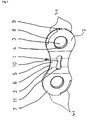
- each ring portion 7 has a perforation 3, which is each equipped with a bolt end-stamping 4.
- Each of the bolt end embossings 4 has an outwardly funnel-shaped widening, in which a not shown, thickened bolt end can be positively received.
- the contour of the outer flap 1 is rounded and is formed by concave edge sections 6 on the connecting region 2 and convex edge sections 41 on the annular regions 7.
- the convex edge portions 41 are in the FIG. 1 right top and bottom left each equipped with a participatedlaschen Abweisefase 8, extending over an angular range of about 90 ° and leak before the tab ends 9.
- an opening 10 with rounded ends 11 which is only optionally available in the chain according to the invention.
- Fig. 2 shows the inside of an outer flap 1 with the perforations 3 and with the optional opening 10.
- the concave edge portions 6 are each provided with an outer flap-catching chamfer 12 which extends in the longitudinal direction over the connecting portion 2.
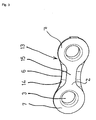
- Fig. 3 the inner plate outer side 15 is shown with two perforations 3 for receiving chain pins 18, not shown.
- the concave edge portions 6 on the connecting portion 2 are equipped with relatively wide optional inner tab Abweisefasen 14.
- the convex edge portions 41 are not chamfered.
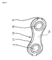
- Fig. 4 shows the inside tab inside 31 of an inner flap 13 with the two perforations 3. These holes 3 are bordered for receiving the chain rollers 20, not shown, each with a tubular collar 16.
- the concave edge portions 6 and convex edge portions 41 have, with the exception of the tab end 9 on a circumferential inner tab catching chamfer 17.
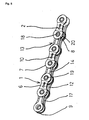
- a chain section with the outer plates 1 and the inner plates 13 is shown.
- the link plates are hingedly connected by means of chain pins 18.
- the bolt ends 19 of the chain pins 18 do not protrude in the axial direction beyond the bolt end impressions 4 of the outer plates 1.
- the outer plates 1 have on the inner sides in the connecting region 2 outer tabs catch 12 and on the outer sides outer tabs Abweisefasen 8.
- Each chain pin 18 is associated with a chain roller 20.
- the inner tab Abweisefasen 14 secure when turning the chain on an adjacent sprocket that both inner plates laterally pass a tooth and not ride on the tooth.
- the inner tabs 17 on the inner sides of the inner tabs serve to form a funnel shape of the largest possible clearance for the engaging teeth.
- the design of these inner tongue catching chamfers 17 is the most important component of the inner tabs 13 according to the invention.
- Fig. 6 shows a portion of the chain 21 and a larger sprocket 22 during the switching from the smaller sprocket, not shown, to the larger sprocket 22, which rotates counterclockwise.
- the chain changing section 30 extends tangentially away from the smaller sprocket toward the larger sprocket 22.
- the chain 21 is shown in the outside view.
- the schematic, shown in phantom, larger sprocket 22 may be a front sprocket on a crank or a rear sprocket on the rear wheel.
- the chain 21 faces the viewer and the larger sprocket 22 lies behind it.
- the larger sprocket 22 faces the viewer, and the chain 21 is behind it.
- the larger sprocket 22 are a Abweis leopard 23 with an indentation 42 and a catch tooth 25 can be seen.
- This view illustrates the function of the outer link Abweisefase 8 in the interaction of the chain 21 and rear multiple sprocket and shows how the outer plate 1 when switching towards the larger sprocket 22, slide along the flank of the laterally recessed Abweisschwes 23 in the direction of a stamping edge 24 can.
- the outer flap Abweisefase 8 at the convex edge portion 41 prevents the outer flap 1 with the left lower edge of the laterally not recessed tooth base gets stuck.
- the non-chamfered, lower right edge of the outer flap 1 is to be supported on the tooth base of the follower tooth 25 and thereby bring the chain 21 to the level of the larger sprocket 22.
- FIG. 7 shows an inner tab 13 according to the invention with the two annular regions 7 and the waisted connection region 2, which has two concave edge portions 6. Centrally in the annular regions 7 holes 3 are shown, which are bordered by collar 16. The peripheral cylindrical outer surfaces of the collar 16 represent the bearing base for the chain rollers 20, not shown. The non-visible outer surface 5 of the inner flap 13 is flat.
- the inner flap is made of a flat raw material.
- the original material thickness is found only radially outward in connection to the collar 16.
- the inside tab inside 31 is somewhat removed from the original material thickness.
- Dividing lines 32 shown represent transitions between adjacent curved surface areas, but no edges.
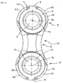
- FIG. 8 also shows the inner tab according to the invention, viewed parallel to the axes of the cylindrical inner surfaces within the collar.
- sectional profile A-A can be seen through the plane of symmetry between the perforations 3 and the section B-B through the central axes 34 of the cylindrical inner surfaces on the collar 16.
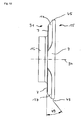
- FIG. 9 shows a sectional view at the section AA through the plane of symmetry between the holes. 3
- the left outer flap outer surface 5 is flat.
- the right boundary of the cut surface which is hatched as usual, is curved, wherein a first curved part surface 44 has a larger radius of curvature or a smaller curvature.
- the adjoining in a tangential transition upwards and downwards edge regions 43 have a larger curvature or a smaller radius of curvature.
- FIG. 10 shows a sectional view at a section BB through the central axes 34 of the cylindrical inner surfaces of the collar 16th
- FIG. 11 shows a section through the central axis of a chain pin of the roller chain according to the invention with a comparison of the shape of the bolt ends 19 before and after the forming operation by a planar tool 35.
- the dashed line corresponds to the state before the forming operation.
- the chain pin 18 is formed as a hollow pin with a through hole 37. Towards the bolt ends 19, the wall thickness 36 of the hollow bolt is reduced by a conical widening of the bore 37, wherein the outer surface of the chain bolt 18 is a cylindrical surface. Thereby, a center line between the cylindrical outer surface of the chain pin 18 on the one hand and the conical widening of the bore 37 on the other hand with respect to the central axis 34 of the perforation towards the bolt end 19 toward radially outwardly inclined, whereby the wall in the sectional view appears obliquely.
- the obliquely appearing wall has the tendency to dodge radially outward, correspondingly plastically deform and a circumferential projection as a stop in terms of movement of the chain pin against the outer flap to form.
- Sufficient space is given to the circumferential projection in that a chamfer is provided on the outer strap outer side 5 at the outlet of the perforation 3 and forms a bolt end embossing 4.
- the forming process can be supplemented by means of a planar tool 35 by one or more additional process steps, in which trained as a truncated cone or cone tools are pressed with corresponding force axially into the bore 37.
- the cone angles can have a different value.
- Fig. 12 combined with Fig. 13 shows the inner tab Fangfase (17) on the inner tab inside (31) in the region of the outer contour (45) of the convex edge portion (41) having a chamfer angle (49) less than 45 degrees between the inner tab Fangfase (17) and the Ring portion (7) on the inside tab inside (31).
- a chamfer angle of 38 degrees has proved to be particularly favorable, wherein the outer contour (45) between the inner tab catch chamfer (17) and inner tab outer side (15) has an extension in the direction parallel to the central axis (34) of 0.3 millimeters
Landscapes
- Engineering & Computer Science (AREA)
- General Engineering & Computer Science (AREA)
- Mechanical Engineering (AREA)
- Gears, Cams (AREA)
Applications Claiming Priority (2)
| Application Number | Priority Date | Filing Date | Title |
|---|---|---|---|
| DE102015011500 | 2015-09-09 | ||
| DE102016009814.7A DE102016009814A1 (de) | 2015-09-09 | 2016-08-12 | Rollenketten-Innenlasche |
Publications (2)
| Publication Number | Publication Date |
|---|---|
| EP3141776A1 true EP3141776A1 (fr) | 2017-03-15 |
| EP3141776B1 EP3141776B1 (fr) | 2023-08-23 |
Family
ID=56893645
Family Applications (1)
| Application Number | Title | Priority Date | Filing Date |
|---|---|---|---|
| EP16001934.5A Active EP3141776B1 (fr) | 2015-09-09 | 2016-09-05 | Attache interieure pour chaine a rouleaux |
Country Status (1)
| Country | Link |
|---|---|
| EP (1) | EP3141776B1 (fr) |
Citations (12)
| Publication number | Priority date | Publication date | Assignee | Title |
|---|---|---|---|---|
| US4642078A (en) | 1984-08-03 | 1987-02-10 | Compagnie Des Transmissions Mecaniques Sedis | Transmission chain |
| DE4330989A1 (de) | 1993-09-13 | 1995-03-16 | Fichtel & Sachs Ag | Kettenschaltung, insbesondere für Fahrräder |
| DE19705018A1 (de) | 1996-03-18 | 1997-09-25 | Campagnolo Srl | Übertragungs-Gliederkette, insbesondere für ein Fahrrad |
| DE69705008T2 (de) * | 1996-09-19 | 2002-03-14 | Sram Corp., Chicago | Treibkette, insbesondere für Fahrrad |
| DE20212596U1 (de) * | 2002-08-16 | 2003-02-06 | KMC Chain Industrial Co., Ltd., Hsin Hua, Tainan | Antriebskette |
| EP1522490A2 (fr) | 2003-10-10 | 2005-04-13 | SRAM Deutschland GmbH | Pignon à bruit réduit |
| US7473198B2 (en) * | 2004-06-01 | 2009-01-06 | Shimano, Inc. | Apparatus for connecting bicycle chain links together |
| EP2141069A2 (fr) | 2008-07-03 | 2010-01-06 | SRAM Deutschland GmbH | Roue dentée à chaîne multiple pour un vélo |
| DE202010008814U1 (de) * | 2009-10-15 | 2010-12-23 | Shimano Inc., Sakai City | Fahrradketteninnenglied |
| EP2535616A2 (fr) | 2011-06-15 | 2012-12-19 | Shimano Inc. | Maillon interne pour chaîne de bicyclette |
| DE102014215928A1 (de) | 2013-09-27 | 2015-04-02 | Shimano Inc. | Fahrradkette |
| DE102014215960A1 (de) | 2013-09-27 | 2015-04-02 | Shimano (Singapore) Pte Ltd. | Fahrradkette |
Family Cites Families (1)
| Publication number | Priority date | Publication date | Assignee | Title |
|---|---|---|---|---|
| CN201155544Y (zh) * | 2007-09-26 | 2008-11-26 | 南京利民机械有限责任公司 | 自行车变速链条的内链板及相应的自行车变速链条 |
-
2016
- 2016-09-05 EP EP16001934.5A patent/EP3141776B1/fr active Active
Patent Citations (12)
| Publication number | Priority date | Publication date | Assignee | Title |
|---|---|---|---|---|
| US4642078A (en) | 1984-08-03 | 1987-02-10 | Compagnie Des Transmissions Mecaniques Sedis | Transmission chain |
| DE4330989A1 (de) | 1993-09-13 | 1995-03-16 | Fichtel & Sachs Ag | Kettenschaltung, insbesondere für Fahrräder |
| DE19705018A1 (de) | 1996-03-18 | 1997-09-25 | Campagnolo Srl | Übertragungs-Gliederkette, insbesondere für ein Fahrrad |
| DE69705008T2 (de) * | 1996-09-19 | 2002-03-14 | Sram Corp., Chicago | Treibkette, insbesondere für Fahrrad |
| DE20212596U1 (de) * | 2002-08-16 | 2003-02-06 | KMC Chain Industrial Co., Ltd., Hsin Hua, Tainan | Antriebskette |
| EP1522490A2 (fr) | 2003-10-10 | 2005-04-13 | SRAM Deutschland GmbH | Pignon à bruit réduit |
| US7473198B2 (en) * | 2004-06-01 | 2009-01-06 | Shimano, Inc. | Apparatus for connecting bicycle chain links together |
| EP2141069A2 (fr) | 2008-07-03 | 2010-01-06 | SRAM Deutschland GmbH | Roue dentée à chaîne multiple pour un vélo |
| DE202010008814U1 (de) * | 2009-10-15 | 2010-12-23 | Shimano Inc., Sakai City | Fahrradketteninnenglied |
| EP2535616A2 (fr) | 2011-06-15 | 2012-12-19 | Shimano Inc. | Maillon interne pour chaîne de bicyclette |
| DE102014215928A1 (de) | 2013-09-27 | 2015-04-02 | Shimano Inc. | Fahrradkette |
| DE102014215960A1 (de) | 2013-09-27 | 2015-04-02 | Shimano (Singapore) Pte Ltd. | Fahrradkette |
Also Published As
| Publication number | Publication date |
|---|---|
| EP3141776B1 (fr) | 2023-08-23 |
Similar Documents
| Publication | Publication Date | Title |
|---|---|---|
| DE102016009814A1 (de) | Rollenketten-Innenlasche | |
| EP3770054B1 (fr) | Agencement de roue dentée multiple pour un moyeu arrière | |
| EP2810864B1 (fr) | Plateau | |
| DE102012025875B3 (de) | Fahrradkettenring für eine Fahrradkurbelanordnung zum Eingreifen in eine Antriebskette | |
| EP2684790B1 (fr) | Galet guide-chaîne pour un dérailleur arrière d'une chaîne de bicyclette et dérailleur arrière doté d'un tel galet guide-chaîne | |
| EP1245862B1 (fr) | Chaîne de transmission pour une bicyclette ou analogue | |
| EP3339158B1 (fr) | Pignon, dispositif à plusieurs pignons et entraînement par roue porteuse doté d'un tel dispositif à plusieurs pignons | |
| DE102017009632A1 (de) | Rollenketten für Fahrräder | |
| EP2319752A2 (fr) | Agencement de pignon multiple pour vélos | |
| EP3318335B1 (fr) | Chaînes à rouleau pour cycle | |
| EP3557094B1 (fr) | Maillon de fermeture à chaînes | |
| EP3567276A1 (fr) | Languette intérieure asymétrique de chaîne de bicyclette, languette extérieure de chaîne de bicyclette et chaîne de bicyclette dotée d'au moins une telle languette | |
| DE102017006618A1 (de) | Ketten-Verschlussglied | |
| DE102014206896A1 (de) | Kette | |
| DE102010009067B4 (de) | Zahnkettentrieb | |
| DE102012106068B4 (de) | Antriebssystem mit einer über einen Zahnkranz geführten Antriebskette | |
| EP2366917B1 (fr) | Chaîne dentaire dotée de chaînes articulées optimisées | |
| EP3141776B1 (fr) | Attache interieure pour chaine a rouleaux | |
| WO2007076777A2 (fr) | Chaine | |
| DE102015214879B4 (de) | Zahnkette und zahnketten-übertragungssystem | |
| DE10159773B4 (de) | Antriebskette für ein Fahrrad oder dergleichen | |
| EP3748191B1 (fr) | Commande optimisé de la longueur de chaîne | |
| EP4571142A1 (fr) | Chaîne de bicyclette commutable à maillons de chaîne uniformément coudés et ensemble pignon coopérant avec celle-ci | |
| WO2022106543A1 (fr) | Rouleau de laminage destiné au laminage, en particulier au galetage de renforcement de vilebrequins, et procédé de laminage avec un rouleau de laminage correspondant |
Legal Events
| Date | Code | Title | Description |
|---|---|---|---|
| PUAI | Public reference made under article 153(3) epc to a published international application that has entered the european phase |
Free format text: ORIGINAL CODE: 0009012 |
|
| STAA | Information on the status of an ep patent application or granted ep patent |
Free format text: STATUS: THE APPLICATION HAS BEEN PUBLISHED |
|
| AK | Designated contracting states |
Kind code of ref document: A1 Designated state(s): AL AT BE BG CH CY CZ DE DK EE ES FI FR GB GR HR HU IE IS IT LI LT LU LV MC MK MT NL NO PL PT RO RS SE SI SK SM TR |
|
| AX | Request for extension of the european patent |
Extension state: BA ME |
|
| STAA | Information on the status of an ep patent application or granted ep patent |
Free format text: STATUS: REQUEST FOR EXAMINATION WAS MADE |
|
| 17P | Request for examination filed |
Effective date: 20170908 |
|
| STAA | Information on the status of an ep patent application or granted ep patent |
Free format text: STATUS: EXAMINATION IS IN PROGRESS |
|
| 17Q | First examination report despatched |
Effective date: 20200103 |
|
| GRAP | Despatch of communication of intention to grant a patent |
Free format text: ORIGINAL CODE: EPIDOSNIGR1 |
|
| STAA | Information on the status of an ep patent application or granted ep patent |
Free format text: STATUS: GRANT OF PATENT IS INTENDED |
|
| INTG | Intention to grant announced |
Effective date: 20230330 |
|
| GRAS | Grant fee paid |
Free format text: ORIGINAL CODE: EPIDOSNIGR3 |
|
| GRAA | (expected) grant |
Free format text: ORIGINAL CODE: 0009210 |
|
| STAA | Information on the status of an ep patent application or granted ep patent |
Free format text: STATUS: THE PATENT HAS BEEN GRANTED |
|
| AK | Designated contracting states |
Kind code of ref document: B1 Designated state(s): AL AT BE BG CH CY CZ DE DK EE ES FI FR GB GR HR HU IE IS IT LI LT LU LV MC MK MT NL NO PL PT RO RS SE SI SK SM TR |
|
| REG | Reference to a national code |
Ref country code: GB Ref legal event code: FG4D Free format text: NOT ENGLISH |
|
| REG | Reference to a national code |
Ref country code: CH Ref legal event code: EP |
|
| P01 | Opt-out of the competence of the unified patent court (upc) registered |
Effective date: 20230801 |
|
| REG | Reference to a national code |
Ref country code: DE Ref legal event code: R096 Ref document number: 502016016028 Country of ref document: DE |
|
| REG | Reference to a national code |
Ref country code: IE Ref legal event code: FG4D Free format text: LANGUAGE OF EP DOCUMENT: GERMAN |
|
| REG | Reference to a national code |
Ref country code: NL Ref legal event code: FP |
|
| REG | Reference to a national code |
Ref country code: LT Ref legal event code: MG9D |
|
| PG25 | Lapsed in a contracting state [announced via postgrant information from national office to epo] |
Ref country code: GR Free format text: LAPSE BECAUSE OF FAILURE TO SUBMIT A TRANSLATION OF THE DESCRIPTION OR TO PAY THE FEE WITHIN THE PRESCRIBED TIME-LIMIT Effective date: 20231124 |
|
| PG25 | Lapsed in a contracting state [announced via postgrant information from national office to epo] |
Ref country code: IS Free format text: LAPSE BECAUSE OF FAILURE TO SUBMIT A TRANSLATION OF THE DESCRIPTION OR TO PAY THE FEE WITHIN THE PRESCRIBED TIME-LIMIT Effective date: 20231223 |
|
| PG25 | Lapsed in a contracting state [announced via postgrant information from national office to epo] |
Ref country code: SE Free format text: LAPSE BECAUSE OF FAILURE TO SUBMIT A TRANSLATION OF THE DESCRIPTION OR TO PAY THE FEE WITHIN THE PRESCRIBED TIME-LIMIT Effective date: 20230823 Ref country code: RS Free format text: LAPSE BECAUSE OF FAILURE TO SUBMIT A TRANSLATION OF THE DESCRIPTION OR TO PAY THE FEE WITHIN THE PRESCRIBED TIME-LIMIT Effective date: 20230823 Ref country code: PT Free format text: LAPSE BECAUSE OF FAILURE TO SUBMIT A TRANSLATION OF THE DESCRIPTION OR TO PAY THE FEE WITHIN THE PRESCRIBED TIME-LIMIT Effective date: 20231226 Ref country code: NO Free format text: LAPSE BECAUSE OF FAILURE TO SUBMIT A TRANSLATION OF THE DESCRIPTION OR TO PAY THE FEE WITHIN THE PRESCRIBED TIME-LIMIT Effective date: 20231123 Ref country code: LV Free format text: LAPSE BECAUSE OF FAILURE TO SUBMIT A TRANSLATION OF THE DESCRIPTION OR TO PAY THE FEE WITHIN THE PRESCRIBED TIME-LIMIT Effective date: 20230823 Ref country code: LT Free format text: LAPSE BECAUSE OF FAILURE TO SUBMIT A TRANSLATION OF THE DESCRIPTION OR TO PAY THE FEE WITHIN THE PRESCRIBED TIME-LIMIT Effective date: 20230823 Ref country code: IS Free format text: LAPSE BECAUSE OF FAILURE TO SUBMIT A TRANSLATION OF THE DESCRIPTION OR TO PAY THE FEE WITHIN THE PRESCRIBED TIME-LIMIT Effective date: 20231223 Ref country code: HR Free format text: LAPSE BECAUSE OF FAILURE TO SUBMIT A TRANSLATION OF THE DESCRIPTION OR TO PAY THE FEE WITHIN THE PRESCRIBED TIME-LIMIT Effective date: 20230823 Ref country code: GR Free format text: LAPSE BECAUSE OF FAILURE TO SUBMIT A TRANSLATION OF THE DESCRIPTION OR TO PAY THE FEE WITHIN THE PRESCRIBED TIME-LIMIT Effective date: 20231124 Ref country code: FI Free format text: LAPSE BECAUSE OF FAILURE TO SUBMIT A TRANSLATION OF THE DESCRIPTION OR TO PAY THE FEE WITHIN THE PRESCRIBED TIME-LIMIT Effective date: 20230823 |
|
| PG25 | Lapsed in a contracting state [announced via postgrant information from national office to epo] |
Ref country code: PL Free format text: LAPSE BECAUSE OF FAILURE TO SUBMIT A TRANSLATION OF THE DESCRIPTION OR TO PAY THE FEE WITHIN THE PRESCRIBED TIME-LIMIT Effective date: 20230823 |
|
| PG25 | Lapsed in a contracting state [announced via postgrant information from national office to epo] |
Ref country code: ES Free format text: LAPSE BECAUSE OF FAILURE TO SUBMIT A TRANSLATION OF THE DESCRIPTION OR TO PAY THE FEE WITHIN THE PRESCRIBED TIME-LIMIT Effective date: 20230823 |
|
| PG25 | Lapsed in a contracting state [announced via postgrant information from national office to epo] |
Ref country code: SM Free format text: LAPSE BECAUSE OF FAILURE TO SUBMIT A TRANSLATION OF THE DESCRIPTION OR TO PAY THE FEE WITHIN THE PRESCRIBED TIME-LIMIT Effective date: 20230823 Ref country code: RO Free format text: LAPSE BECAUSE OF FAILURE TO SUBMIT A TRANSLATION OF THE DESCRIPTION OR TO PAY THE FEE WITHIN THE PRESCRIBED TIME-LIMIT Effective date: 20230823 Ref country code: ES Free format text: LAPSE BECAUSE OF FAILURE TO SUBMIT A TRANSLATION OF THE DESCRIPTION OR TO PAY THE FEE WITHIN THE PRESCRIBED TIME-LIMIT Effective date: 20230823 Ref country code: EE Free format text: LAPSE BECAUSE OF FAILURE TO SUBMIT A TRANSLATION OF THE DESCRIPTION OR TO PAY THE FEE WITHIN THE PRESCRIBED TIME-LIMIT Effective date: 20230823 Ref country code: DK Free format text: LAPSE BECAUSE OF FAILURE TO SUBMIT A TRANSLATION OF THE DESCRIPTION OR TO PAY THE FEE WITHIN THE PRESCRIBED TIME-LIMIT Effective date: 20230823 Ref country code: CZ Free format text: LAPSE BECAUSE OF FAILURE TO SUBMIT A TRANSLATION OF THE DESCRIPTION OR TO PAY THE FEE WITHIN THE PRESCRIBED TIME-LIMIT Effective date: 20230823 Ref country code: SK Free format text: LAPSE BECAUSE OF FAILURE TO SUBMIT A TRANSLATION OF THE DESCRIPTION OR TO PAY THE FEE WITHIN THE PRESCRIBED TIME-LIMIT Effective date: 20230823 |
|
| REG | Reference to a national code |
Ref country code: CH Ref legal event code: PL |
|
| PG25 | Lapsed in a contracting state [announced via postgrant information from national office to epo] |
Ref country code: LU Free format text: LAPSE BECAUSE OF NON-PAYMENT OF DUE FEES Effective date: 20230905 |
|
| REG | Reference to a national code |
Ref country code: DE Ref legal event code: R097 Ref document number: 502016016028 Country of ref document: DE |
|
| REG | Reference to a national code |
Ref country code: BE Ref legal event code: MM Effective date: 20230930 |
|
| PG25 | Lapsed in a contracting state [announced via postgrant information from national office to epo] |
Ref country code: LU Free format text: LAPSE BECAUSE OF NON-PAYMENT OF DUE FEES Effective date: 20230905 Ref country code: IT Free format text: LAPSE BECAUSE OF FAILURE TO SUBMIT A TRANSLATION OF THE DESCRIPTION OR TO PAY THE FEE WITHIN THE PRESCRIBED TIME-LIMIT Effective date: 20230823 Ref country code: MC Free format text: LAPSE BECAUSE OF FAILURE TO SUBMIT A TRANSLATION OF THE DESCRIPTION OR TO PAY THE FEE WITHIN THE PRESCRIBED TIME-LIMIT Effective date: 20230823 |
|
| PLBE | No opposition filed within time limit |
Free format text: ORIGINAL CODE: 0009261 |
|
| STAA | Information on the status of an ep patent application or granted ep patent |
Free format text: STATUS: NO OPPOSITION FILED WITHIN TIME LIMIT |
|
| REG | Reference to a national code |
Ref country code: IE Ref legal event code: MM4A |
|
| PG25 | Lapsed in a contracting state [announced via postgrant information from national office to epo] |
Ref country code: IE Free format text: LAPSE BECAUSE OF NON-PAYMENT OF DUE FEES Effective date: 20230905 |
|
| PG25 | Lapsed in a contracting state [announced via postgrant information from national office to epo] |
Ref country code: CH Free format text: LAPSE BECAUSE OF NON-PAYMENT OF DUE FEES Effective date: 20230930 |
|
| GBPC | Gb: european patent ceased through non-payment of renewal fee |
Effective date: 20231123 |
|
| 26N | No opposition filed |
Effective date: 20240524 |
|
| PG25 | Lapsed in a contracting state [announced via postgrant information from national office to epo] |
Ref country code: CH Free format text: LAPSE BECAUSE OF NON-PAYMENT OF DUE FEES Effective date: 20230930 Ref country code: IE Free format text: LAPSE BECAUSE OF NON-PAYMENT OF DUE FEES Effective date: 20230905 Ref country code: SI Free format text: LAPSE BECAUSE OF FAILURE TO SUBMIT A TRANSLATION OF THE DESCRIPTION OR TO PAY THE FEE WITHIN THE PRESCRIBED TIME-LIMIT Effective date: 20230823 |
|
| PG25 | Lapsed in a contracting state [announced via postgrant information from national office to epo] |
Ref country code: BE Free format text: LAPSE BECAUSE OF NON-PAYMENT OF DUE FEES Effective date: 20230930 |
|
| PG25 | Lapsed in a contracting state [announced via postgrant information from national office to epo] |
Ref country code: GB Free format text: LAPSE BECAUSE OF NON-PAYMENT OF DUE FEES Effective date: 20231123 |
|
| PG25 | Lapsed in a contracting state [announced via postgrant information from national office to epo] |
Ref country code: GB Free format text: LAPSE BECAUSE OF NON-PAYMENT OF DUE FEES Effective date: 20231123 |
|
| PG25 | Lapsed in a contracting state [announced via postgrant information from national office to epo] |
Ref country code: BG Free format text: LAPSE BECAUSE OF FAILURE TO SUBMIT A TRANSLATION OF THE DESCRIPTION OR TO PAY THE FEE WITHIN THE PRESCRIBED TIME-LIMIT Effective date: 20230823 |
|
| REG | Reference to a national code |
Ref country code: AT Ref legal event code: MM01 Ref document number: 1602915 Country of ref document: AT Kind code of ref document: T Effective date: 20230905 |
|
| PG25 | Lapsed in a contracting state [announced via postgrant information from national office to epo] |
Ref country code: BG Free format text: LAPSE BECAUSE OF FAILURE TO SUBMIT A TRANSLATION OF THE DESCRIPTION OR TO PAY THE FEE WITHIN THE PRESCRIBED TIME-LIMIT Effective date: 20230823 |
|
| PG25 | Lapsed in a contracting state [announced via postgrant information from national office to epo] |
Ref country code: AT Free format text: LAPSE BECAUSE OF NON-PAYMENT OF DUE FEES Effective date: 20230905 |
|
| PG25 | Lapsed in a contracting state [announced via postgrant information from national office to epo] |
Ref country code: AT Free format text: LAPSE BECAUSE OF NON-PAYMENT OF DUE FEES Effective date: 20230905 |
|
| PG25 | Lapsed in a contracting state [announced via postgrant information from national office to epo] |
Ref country code: CY Free format text: LAPSE BECAUSE OF FAILURE TO SUBMIT A TRANSLATION OF THE DESCRIPTION OR TO PAY THE FEE WITHIN THE PRESCRIBED TIME-LIMIT; INVALID AB INITIO Effective date: 20160905 |
|
| PG25 | Lapsed in a contracting state [announced via postgrant information from national office to epo] |
Ref country code: HU Free format text: LAPSE BECAUSE OF FAILURE TO SUBMIT A TRANSLATION OF THE DESCRIPTION OR TO PAY THE FEE WITHIN THE PRESCRIBED TIME-LIMIT; INVALID AB INITIO Effective date: 20160905 |
|
| PGFP | Annual fee paid to national office [announced via postgrant information from national office to epo] |
Ref country code: DE Payment date: 20250925 Year of fee payment: 10 |
|
| PGFP | Annual fee paid to national office [announced via postgrant information from national office to epo] |
Ref country code: NL Payment date: 20250918 Year of fee payment: 10 |
|
| PGFP | Annual fee paid to national office [announced via postgrant information from national office to epo] |
Ref country code: FR Payment date: 20250922 Year of fee payment: 10 |
|
| PG25 | Lapsed in a contracting state [announced via postgrant information from national office to epo] |
Ref country code: TR Free format text: LAPSE BECAUSE OF FAILURE TO SUBMIT A TRANSLATION OF THE DESCRIPTION OR TO PAY THE FEE WITHIN THE PRESCRIBED TIME-LIMIT Effective date: 20230823 |