EP3141778B1 - Axiales übertragungssystem - Google Patents
Axiales übertragungssystem Download PDFInfo
- Publication number
- EP3141778B1 EP3141778B1 EP15788808.2A EP15788808A EP3141778B1 EP 3141778 B1 EP3141778 B1 EP 3141778B1 EP 15788808 A EP15788808 A EP 15788808A EP 3141778 B1 EP3141778 B1 EP 3141778B1
- Authority
- EP
- European Patent Office
- Prior art keywords
- disc
- masses
- output shaft
- transmission system
- pulley
- Prior art date
- Legal status (The legal status is an assumption and is not a legal conclusion. Google has not performed a legal analysis and makes no representation as to the accuracy of the status listed.)
- Active
Links
Images

Classifications
-
- F—MECHANICAL ENGINEERING; LIGHTING; HEATING; WEAPONS; BLASTING
- F16—ENGINEERING ELEMENTS AND UNITS; GENERAL MEASURES FOR PRODUCING AND MAINTAINING EFFECTIVE FUNCTIONING OF MACHINES OR INSTALLATIONS; THERMAL INSULATION IN GENERAL
- F16H—GEARING
- F16H55/00—Elements with teeth or friction surfaces for conveying motion; Worms, pulleys or sheaves for gearing mechanisms
- F16H55/32—Friction members
- F16H55/52—Pulleys or friction discs of adjustable construction
- F16H55/56—Pulleys or friction discs of adjustable construction of which the bearing parts are relatively axially adjustable
- F16H55/563—Pulleys or friction discs of adjustable construction of which the bearing parts are relatively axially adjustable actuated by centrifugal masses
-
- F—MECHANICAL ENGINEERING; LIGHTING; HEATING; WEAPONS; BLASTING
- F16—ENGINEERING ELEMENTS AND UNITS; GENERAL MEASURES FOR PRODUCING AND MAINTAINING EFFECTIVE FUNCTIONING OF MACHINES OR INSTALLATIONS; THERMAL INSULATION IN GENERAL
- F16H—GEARING
- F16H57/00—General details of gearing
- F16H57/04—Features relating to lubrication or cooling or heating
- F16H57/048—Type of gearings to be lubricated, cooled or heated
- F16H57/0487—Friction gearings
- F16H57/0489—Friction gearings with endless flexible members, e.g. belt CVTs
-
- F—MECHANICAL ENGINEERING; LIGHTING; HEATING; WEAPONS; BLASTING
- F16—ENGINEERING ELEMENTS AND UNITS; GENERAL MEASURES FOR PRODUCING AND MAINTAINING EFFECTIVE FUNCTIONING OF MACHINES OR INSTALLATIONS; THERMAL INSULATION IN GENERAL
- F16D—COUPLINGS FOR TRANSMITTING ROTATION; CLUTCHES; BRAKES
- F16D43/00—Automatic clutches
- F16D43/02—Automatic clutches actuated entirely mechanically
- F16D43/24—Automatic clutches actuated entirely mechanically controlled by acceleration or deceleration of angular speed
Definitions
- the present invention relates to a device that has been especially designed to form an axial transmission system that considerably improves the performance of current variable speed drives.
- the object of the invention is to provide an inertial axial transmission system in which an exponential speed variation takes place depending on the movement caused by the inertia of the device and having a structure such that it prevents performance loss due to movements of some of its internal parts due to said inertial effect in directions that do not provide the device with any functionality.
- the invention can be applied in the field of automatic transmissions for either two-stroke or four-stroke engines, although it can also be applied in other fields, such as in automatic transmission systems, including electric vehicles and bicycles.
- variable speed drive devices such as variable speed cam drives, variable speed roller drives, or variable speed ball drives, all of them having the common denominator of the enormous difficulty involved in servicing the engine transmission.
- Patent document P200003019 discloses a variable speed cross drive, designed for any automatic engine, which consists of a variable pulley for V-belts, comprising two smooth frustoconical discs, between which there is formed a groove in which a V-belt is directly applied, having a disc-shaped plate, the entire assembly being coaxially mounted and secured to the rotational shaft of a driving shaft, the disc-shaped plate and a first disc being stationary and a second disc being mobile in the axial direction of the shaft due to its own inertia.
- the device defines a variable pulley through means for movement of the mobile disc, suitable for gradually moving the latter closer to the stationary disc as the rotational speed of the assembly increases, the width of the pulley groove decreasing and therefore increasing the pitch diameter of the pulley, and vice versa, so the effective radius on which the transmission torque is applied, and accordingly the speed on the element actuating the other end of said belt, vary.
- the means for axial movement consist of a number of masses or sliders that are arranged with their axes inclined several degrees with respect to the driving shaft and can be moved axially with respect to said driving shaft. They are radially and uniformly distributed, housed in holes machined on the outer face of the mobile disc facing the disc-shaped plate and encased between the mobile disc and the disc-shaped plate, all of which is suitable such that, for zero or low rotational speed of the assembly, the sliders are located entirely inside their holes and the mobile disc is in the position farthest away from the stationary disc, moving from inside their holes towards the disc-shaped plate, according to the rotational speed, and pushing the mobile disc towards the stationary disc, thereby reducing the separation distance between both discs and reduces the width of the pulley groove, increasing the pitch diameter thereof.
- the masses have a cylindrical configuration, enabling them rotate in their housings, carrying out angular or rotational movement, which involves energy that is not utilized. Furthermore, this rotational possibility of the masses that can be moved means that they will gradually be sharpened, forming a tip hindering their movement on the disc-shaped plate.
- the drive wheel is associated with a pulley that has a specific, and accordingly invariable profile, such that the radius of action of the belt on said pulley is always the same, such that the torque that must be overcome to initially move the wheel is significantly greater than when it is in motion, so it would be desirable to have means that allowed regulating the radius of action of the belt on the drive wheel depending on the angular speed at which the latter is moving.
- the axial transmission system proposed by the invention is of the type described in the preamble of claim 1.
- This system has features that seek to solve a series of problems in a fully satisfactory manner as a result of a highly effective and novel structure involving both the driving pulley associated with a drive shaft or crankshaft or driving shaft, and the driven pulley associated with an output shaft, thereby achieving a greater reduction in starting torque and higher speeds when the system is in motion, resulting in greater acceleration and optimal utilization of the energy supplied to the driving pulley.
- a feature of the invention consists of the features of claim 1.
- the inertial movement of said masses, which are encased between the mobile disc of the driving pulley and said bell-shaped cover, means that for zero or low rotational speed of the drive shaft, the sliding masses are located entirely inside the respective housings and the mobile disc is in the position farthest away from the stationary pulley, defining a wide groove in which the belt tends to reach the minimum radius allowed by the device.
- this feature that prevents the masses from rotating inside the respective housings assures suitable contact between the masses and the bell-shaped cover and reduces losses of energy due to friction.
- At least one of the discs of the driving pulley has a variable-radius curved generatrix on the face forming the contact surface with the belt, such that an exponential change, instead of a linear change in speed is achieved, working at all times with the radius which is best suited for optimizing system response, allowing a larger V-belt path with a smaller device height.
- This system has features that seek to prevent the working temperature of the driving pulley from being increased too much due to the masses that can be moved rubbing against the bell-shaped cover and to prevent dirt from being able to enter and build up in the area where said bell-shaped cover comes into contact with the masses.
- the driving pulley comprises inside the bell-shaped cover a fan that helps cool the system, helping to eliminate the heat produced by friction.
- the mobile disc of said driving pulley comprises cooling grooves on its front face on the perimeter thereof.
- the driven pulley has a stationary disc secured to an output shaft and a mobile disc provided with means for movement in the axial direction and as a result of its own inertia with respect to the output shaft.
- These means for movement of the mobile disc of the driven pulley in the axial direction with respect to the output shaft comprise a tubular neck mounted on the output shaft, said tubular neck being provided with two groups of oblique notches with different angles of inclination for optionally inserting lugs for integrally securing same to the output shaft.
- the possibility of inserting the lugs in the oblique notches that have more or less inclination allows the mobile disc of the driven pulley to move as a result of its own inertia with respect to the lugs, guided by the oblique notches used in each case offering the system two limit working positions corresponding precisely with the upper and lower ends of said notches, such that in one of said limit positions of the mobile disc, the driven pulley provides a maximum radius for supporting the belt, offering high torque at low speeds; whereas in the other limit position of the disc that can be moved, the driven pulley provides a minimum radius for supporting the belt and accordingly the maximum rotational speed of the driven pulley and of the output shaft.
- the number of notches of the tubular neck is twice the number of lugs that can be coupled in the output shaft, such that the notches having different inclinations form two alternating or angularly offset groups, which enables mounting the lugs on the tubular neck of the mobile disc of the driven pulley in the group of notches having more or less inclination for the purpose of obtaining a higher torque or a faster change in speed, depending on the specific needs of each application.
- the disc that can be moved of the driven pulley is aided by an elastic element which tends to keep it in the position in which it moves closest to the stationary disc of said driven pulley when rotational inertia is not enough.
- an embodiment of the system of the invention can be seen, including a driving pulley (1) mounted on a drive shaft (10) operated in this case by a motor (M) and a driven pulley (2) mounted in this case on an output shaft (20), both the driving pulley (1) and the driven pulley (2) being associated by a V-belt (3).
- the driving pulley (1) consists of a stationary disc (11) and a mobile disc (12) provided with axial movement along the drive shaft (10); the driven pulley (2) likewise has a stationary disc (21) secured to the output shaft (20) and a mobile disc (22) that can be moved in the axial direction by its own inertia with respect to the output shaft (20).
- the axial movement of the mobile discs (12, 22) of the driving and driven pulleys allows the system to vary the drive shaft (10)-output shaft (20) speed ratio.
- the mobile disc (12) of the driving pulley (1) has on its outer face a series of housings (13) inclined in diverging directions and in which there are housed respective masses (14) that can be moved inertially against a curved bell-shaped cover (4) rotating integrally with the drive shaft (10) depicted in Figures 3 and 4 .
- the housings (13) and masses (14) have a non-cylindrical configuration, in this case a trapezoidal section with rounded edges, and ending at the front or projecting end in a rounded spherical cap-like configuration forming the contact surface with the inner surface of the bell-shaped cover (4).
- the masses (14) gradually project due to their own inertia from the respective housings (13), coming into contact with the inner surface of the bell-shaped cover (4) and causing the mobile disc (12) to move closer to the stationary disc of the driving pulley (1) due to the inclined and diverging arrangement of said masses.
- the driving pulley comprises inside the bell-shaped cover (4) a fan (15) for cooling the system and expelling possible particles that get into the space comprised between the mobile disc (12) and the bell-shaped cover (4), keeping the area in which the masses (14) come into contact with said bell-shaped cover (4) clean.
- the mobile disc (12) of the driving pulley (1) comprises on its outer face grooves (16) on the perimeter thereof to help dissipate the heat generated by the different parts associated with same rubbing against one another.
- the mobile disc (12) of the driving pulley (1) is mounted by means of arranging a bushing (17) on a bolt (18) treated with titanium nitride in order to achieve high hardness and a low coefficient of friction during axial movement of said mobile disc.
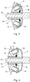
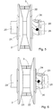
- FIG. 5 and 6 shows the driven pulley (2) mounted on an output shaft (20) and formed by a stationary disc (21) and a mobile disc (22) having, for the purpose of mounting with the possibility of axial movement with respect to the output shaft (20), a tubular neck (23) provided with oblique notches (24, 25) with different angles of inclination for the optional insertion of lugs (26) in one group of notches or the other for integrally securing same to the output shaft (20).
- the tubular neck (23) is detachable and is screw mounted on the mobile disc (22) of the driven pulley (2).
- the mobile disc (22) of the driven pulley (2) will be aided by an elastic element such as a spring or the like, not depicted, which tends to move it towards the stationary disc of the driven pulley.
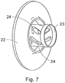
- Figure 7 shows the mobile disc (22) of the driven pulley (2) and the tubular neck (23) provided with two sets of alternating notches (24) with different angles of inclination ( ⁇ , ⁇ ).
Landscapes
- Engineering & Computer Science (AREA)
- General Engineering & Computer Science (AREA)
- Mechanical Engineering (AREA)
- Transmissions By Endless Flexible Members (AREA)
- Pulleys (AREA)
- Transmission Devices (AREA)
Claims (4)
- Axiales Übertragungssystem, umfassend:- eine treibende Riemenscheibe (1), die an einer Antriebswelle (10) montiert ist, umfassend eine stationäre Scheibe (11), die an der Antriebswelle (10) befestigt ist, und eine bewegliche Scheibe (12), die axial beweglich ist, wobei eine Außenfläche der beweglichen Scheibe (12) eine Reihe von Aufnahmen (13) aufweist, die in Bezug auf eine Richtung vertikal oder senkrecht zu der Drehachse der Vorrichtung geneigt sind und Massen (14) enthalten, die träge gegen eine Abdeckung (4) bewegt werden können, die sich integral mit der Antriebswelle (10) dreht;- eine getriebene Riemenscheibe (2), die an einer Abtriebswelle (20) montiert ist, umfassend eine stationäre Scheibe (21), die an der Abtriebswelle (20) befestigt ist, und eine bewegliche Scheibe (22), die aufgrund ihrer eigenen Trägheit in Bezug auf die Abtriebswelle (20) in der axialen Richtung beweglich ist, und- einen Riemen (3), welcher die treibende und die getriebene Riemenscheibe (1, 2) in Rotation miteinander verbindet; undwobei die Massen (14) ein vorstehendes Ende in einer abgerundeten, halbkugelförmigen, kappenartigen Konfiguration haben, die eine Kontaktfläche mit der Innenfläche der Abdeckung (4) ausbildet, und wobei die Abdeckung (4) in einer glockenförmigen Konfiguration abgerundet ist;
dadurch gekennzeichnet, dass die Aufnahmen (13) und die Massen (14) eine trapezförmige Konfiguration mit abgerundeten Kanten aufweisen, die Mittel zum Führen der Massen (14) in der axialen Richtung definieren und verhindern, dass sich die Massen (14) innerhalb ihrer jeweiligen Aufnahmen (13) drehen. - Axiales Übertragungssystem nach Anspruch 1, dadurch gekennzeichnet, dass die treibende Riemenscheibe (1) innerhalb der glockenförmigen Abdeckung (4) einen Lüfter (15) umfasst, der zur Kühlung des Systems beiträgt.
- Axiales Übertragungssystem nach Anspruch 2, dadurch gekennzeichnet, dass die bewegliche Scheibe (11) der treibenden Riemenscheibe (1) an ihrem Umfang Kühlnuten (16) umfasst.
- Axiales Übertragungssystem nach Anspruch 1, dadurch gekennzeichnet, dass die Mittel zur Bewegung in der axialen Richtung in Bezug auf die Abtriebswelle (20) der mobilen Scheibe (22) der getriebenen Scheibe (2) einen rohrförmigen Hals (23) umfassen, der an der Abtriebswelle montiert ist und mit zwei Gruppen von schrägen Ausnehmungen (24, 25) mit unterschiedlichen Neigungswinkeln bereitgestellt ist, um gegebenenfalls Ansätze (26) einzusetzen, um diese integral an der Abtriebswelle (20) zu befestigen.
Applications Claiming Priority (2)
| Application Number | Priority Date | Filing Date | Title |
|---|---|---|---|
| ES201430682A ES2491440B1 (es) | 2014-05-09 | 2014-05-09 | Sistema axial de transmisión |
| PCT/ES2015/070350 WO2015169991A1 (es) | 2014-05-09 | 2015-04-28 | Sistema axial de transmisión |
Publications (3)
| Publication Number | Publication Date |
|---|---|
| EP3141778A1 EP3141778A1 (de) | 2017-03-15 |
| EP3141778A4 EP3141778A4 (de) | 2018-02-21 |
| EP3141778B1 true EP3141778B1 (de) | 2020-06-03 |
Family
ID=51452830
Family Applications (1)
| Application Number | Title | Priority Date | Filing Date |
|---|---|---|---|
| EP15788808.2A Active EP3141778B1 (de) | 2014-05-09 | 2015-04-28 | Axiales übertragungssystem |
Country Status (6)
| Country | Link |
|---|---|
| EP (1) | EP3141778B1 (de) |
| JP (1) | JP6568543B2 (de) |
| CN (1) | CN106662235B (de) |
| BR (1) | BR112016026237B1 (de) |
| ES (2) | ES2491440B1 (de) |
| WO (1) | WO2015169991A1 (de) |
Families Citing this family (3)
| Publication number | Priority date | Publication date | Assignee | Title |
|---|---|---|---|---|
| JP2022534972A (ja) * | 2019-05-27 | 2022-08-04 | イェシル コンプレサー クリマ タサリム イマラト サナイ ヴェ ティジャーレット リミテッド シルケティ | 自転車のためのcvt自動バリエータ変速機 |
| CN111779805B (zh) * | 2020-07-10 | 2023-08-25 | 隆鑫通用动力股份有限公司 | 变速器从动盘及变速器 |
| WO2025100589A1 (ko) * | 2023-11-08 | 2025-05-15 | 엘지전자 주식회사 | 디스플레이 디바이스 |
Family Cites Families (15)
| Publication number | Priority date | Publication date | Assignee | Title |
|---|---|---|---|---|
| JPS5116582B2 (de) * | 1972-12-12 | 1976-05-25 | ||
| JPS5635564Y2 (de) * | 1974-06-07 | 1981-08-21 | ||
| FR2502720B1 (fr) * | 1981-03-24 | 1985-10-04 | Motobecane Ateliers | Double variateur de vitesse |
| FR2519109B1 (de) * | 1981-12-29 | 1988-08-26 | Honda Motor Co Ltd | |
| JPS62118149A (ja) * | 1985-11-15 | 1987-05-29 | Honda Motor Co Ltd | Vベルト無段変速機 |
| JPH03128789A (ja) * | 1989-07-13 | 1991-05-31 | Honda Motor Co Ltd | 電動式車両 |
| JPH05332411A (ja) * | 1992-05-29 | 1993-12-14 | Suzuki Motor Corp | Vベルト自動変速機のドライブvプーリ |
| ES2222052B1 (es) * | 2000-12-18 | 2006-05-16 | Juan Costa Pujadas | Variador transversal. |
| JP4293796B2 (ja) * | 2003-01-31 | 2009-07-08 | ヤマハ発動機株式会社 | Vベルト式無段変速機の冷却構造 |
| TWI225912B (en) * | 2003-09-12 | 2005-01-01 | Ind Tech Res Inst | The mechanism for reverse gear of a belt-type continuously variable transmission |
| JP5030413B2 (ja) * | 2005-11-07 | 2012-09-19 | ヤマハ発動機株式会社 | 鞍乗型車両 |
| JP2009180356A (ja) * | 2008-01-31 | 2009-08-13 | Honda Motor Co Ltd | パワーユニット |
| ITAN20080017A1 (it) * | 2008-04-14 | 2009-10-15 | Claudio Luzi | Dispositivo variatore di velocita' |
| ES1069285Y (es) * | 2008-11-26 | 2009-06-04 | Pujadas Joan Costa | Variador de velocidad con lubricacion en seco |
| ITMI20110823A1 (it) * | 2011-05-12 | 2012-11-13 | Catai S R L | Frizione a disco di attrito con innesto/disinnesto centrifugo |
-
2014
- 2014-05-09 ES ES201430682A patent/ES2491440B1/es active Active
-
2015
- 2015-04-28 JP JP2016567537A patent/JP6568543B2/ja active Active
- 2015-04-28 WO PCT/ES2015/070350 patent/WO2015169991A1/es not_active Ceased
- 2015-04-28 ES ES15788808T patent/ES2811903T3/es active Active
- 2015-04-28 BR BR112016026237-9A patent/BR112016026237B1/pt active IP Right Grant
- 2015-04-28 EP EP15788808.2A patent/EP3141778B1/de active Active
- 2015-04-28 CN CN201580036087.0A patent/CN106662235B/zh active Active
Non-Patent Citations (1)
| Title |
|---|
| None * |
Also Published As
| Publication number | Publication date |
|---|---|
| BR112016026237A2 (pt) | 2017-08-15 |
| CN106662235A (zh) | 2017-05-10 |
| ES2811903T3 (es) | 2021-03-15 |
| BR112016026237B1 (pt) | 2023-04-04 |
| EP3141778A4 (de) | 2018-02-21 |
| BR112016026237A8 (pt) | 2023-02-07 |
| ES2491440B1 (es) | 2015-05-25 |
| CN106662235B (zh) | 2020-06-30 |
| EP3141778A1 (de) | 2017-03-15 |
| JP6568543B2 (ja) | 2019-08-28 |
| WO2015169991A1 (es) | 2015-11-12 |
| JP2017516040A (ja) | 2017-06-15 |
| ES2491440A1 (es) | 2014-09-05 |
Similar Documents
| Publication | Publication Date | Title |
|---|---|---|
| EP3141778B1 (de) | Axiales übertragungssystem | |
| CN103818186B (zh) | 用于自行车的飞轮轮毂 | |
| CN1025363C (zh) | 一种具有弹性偏压皮带接触元件的可变直径皮带轮的连续可变传动系统 | |
| CN106015329B (zh) | 一种往复运动轴承机构以及一种往复运动机构 | |
| KR102378944B1 (ko) | 변속기 및 이러한 변속기를 구비한 차량 | |
| CN108916264B (zh) | 一种基于磁铁控制钢珠驱动的建筑使用的扭矩限制器 | |
| US3800608A (en) | Variable diameter v-belt pulley assembly | |
| CN104343912A (zh) | 螺旋导向无级变速离合器 | |
| RU2003132074A (ru) | Способ и устройство для изготовления дисков бесступенчатой коробки передач | |
| RU143728U1 (ru) | Ведущий шкив вариатора | |
| US20170184179A1 (en) | Drive belt with a carrier ring and transverse segments | |
| KR200309174Y1 (ko) | 벨트구동식 무단변속기 | |
| EP1311777B1 (de) | Konus mit drehmoment-übertragungssegmenten | |
| KR100516779B1 (ko) | 원심추를 이용한 자동무단변속장치 | |
| CN206617536U (zh) | 滚柱摩擦式单向皮带轮 | |
| KR200379031Y1 (ko) | 벨트 구동식 무단 변속기 | |
| JP2017223363A (ja) | ウエイト装置 | |
| JPS62451Y2 (de) | ||
| CN209743423U (zh) | 一种摩托车的离合主动轮组件 | |
| JP2001519506A (ja) | 無段階に調節可能な変換比を有する伝動装置 | |
| CN107208759B (zh) | 具有增加的速度比覆盖范围的无级变速器和用于这种变速器的速度比控制方法 | |
| JP2003028261A (ja) | ボールねじ装置 | |
| SU889955A1 (ru) | Центробежна муфта | |
| RU36473U1 (ru) | Автоматический клиноременный вариатор | |
| JP4099952B2 (ja) | ボールねじ装置 |
Legal Events
| Date | Code | Title | Description |
|---|---|---|---|
| STAA | Information on the status of an ep patent application or granted ep patent |
Free format text: STATUS: THE INTERNATIONAL PUBLICATION HAS BEEN MADE |
|
| PUAI | Public reference made under article 153(3) epc to a published international application that has entered the european phase |
Free format text: ORIGINAL CODE: 0009012 |
|
| STAA | Information on the status of an ep patent application or granted ep patent |
Free format text: STATUS: REQUEST FOR EXAMINATION WAS MADE |
|
| 17P | Request for examination filed |
Effective date: 20161125 |
|
| AK | Designated contracting states |
Kind code of ref document: A1 Designated state(s): AL AT BE BG CH CY CZ DE DK EE ES FI FR GB GR HR HU IE IS IT LI LT LU LV MC MK MT NL NO PL PT RO RS SE SI SK SM TR |
|
| AX | Request for extension of the european patent |
Extension state: BA ME |
|
| RIN1 | Information on inventor provided before grant (corrected) |
Inventor name: PALLARES MATEOS, XAVIER |
|
| DAV | Request for validation of the european patent (deleted) | ||
| DAX | Request for extension of the european patent (deleted) | ||
| A4 | Supplementary search report drawn up and despatched |
Effective date: 20180119 |
|
| RIC1 | Information provided on ipc code assigned before grant |
Ipc: F16D 43/14 20060101ALI20180115BHEP Ipc: F16H 57/04 20100101ALI20180115BHEP Ipc: F16H 55/56 20060101AFI20180115BHEP |
|
| STAA | Information on the status of an ep patent application or granted ep patent |
Free format text: STATUS: EXAMINATION IS IN PROGRESS |
|
| 17Q | First examination report despatched |
Effective date: 20180904 |
|
| GRAP | Despatch of communication of intention to grant a patent |
Free format text: ORIGINAL CODE: EPIDOSNIGR1 |
|
| STAA | Information on the status of an ep patent application or granted ep patent |
Free format text: STATUS: GRANT OF PATENT IS INTENDED |
|
| INTG | Intention to grant announced |
Effective date: 20191121 |
|
| GRAS | Grant fee paid |
Free format text: ORIGINAL CODE: EPIDOSNIGR3 |
|
| GRAA | (expected) grant |
Free format text: ORIGINAL CODE: 0009210 |
|
| STAA | Information on the status of an ep patent application or granted ep patent |
Free format text: STATUS: THE PATENT HAS BEEN GRANTED |
|
| AK | Designated contracting states |
Kind code of ref document: B1 Designated state(s): AL AT BE BG CH CY CZ DE DK EE ES FI FR GB GR HR HU IE IS IT LI LT LU LV MC MK MT NL NO PL PT RO RS SE SI SK SM TR |
|
| REG | Reference to a national code |
Ref country code: GB Ref legal event code: FG4D |
|
| REG | Reference to a national code |
Ref country code: CH Ref legal event code: EP Ref country code: AT Ref legal event code: REF Ref document number: 1277344 Country of ref document: AT Kind code of ref document: T Effective date: 20200615 |
|
| REG | Reference to a national code |
Ref country code: DE Ref legal event code: R096 Ref document number: 602015053828 Country of ref document: DE |
|
| REG | Reference to a national code |
Ref country code: LT Ref legal event code: MG4D |
|
| PG25 | Lapsed in a contracting state [announced via postgrant information from national office to epo] |
Ref country code: LT Free format text: LAPSE BECAUSE OF FAILURE TO SUBMIT A TRANSLATION OF THE DESCRIPTION OR TO PAY THE FEE WITHIN THE PRESCRIBED TIME-LIMIT Effective date: 20200603 Ref country code: NO Free format text: LAPSE BECAUSE OF FAILURE TO SUBMIT A TRANSLATION OF THE DESCRIPTION OR TO PAY THE FEE WITHIN THE PRESCRIBED TIME-LIMIT Effective date: 20200903 Ref country code: GR Free format text: LAPSE BECAUSE OF FAILURE TO SUBMIT A TRANSLATION OF THE DESCRIPTION OR TO PAY THE FEE WITHIN THE PRESCRIBED TIME-LIMIT Effective date: 20200904 Ref country code: SE Free format text: LAPSE BECAUSE OF FAILURE TO SUBMIT A TRANSLATION OF THE DESCRIPTION OR TO PAY THE FEE WITHIN THE PRESCRIBED TIME-LIMIT Effective date: 20200603 Ref country code: FI Free format text: LAPSE BECAUSE OF FAILURE TO SUBMIT A TRANSLATION OF THE DESCRIPTION OR TO PAY THE FEE WITHIN THE PRESCRIBED TIME-LIMIT Effective date: 20200603 |
|
| REG | Reference to a national code |
Ref country code: NL Ref legal event code: MP Effective date: 20200603 |
|
| PG25 | Lapsed in a contracting state [announced via postgrant information from national office to epo] |
Ref country code: HR Free format text: LAPSE BECAUSE OF FAILURE TO SUBMIT A TRANSLATION OF THE DESCRIPTION OR TO PAY THE FEE WITHIN THE PRESCRIBED TIME-LIMIT Effective date: 20200603 Ref country code: RS Free format text: LAPSE BECAUSE OF FAILURE TO SUBMIT A TRANSLATION OF THE DESCRIPTION OR TO PAY THE FEE WITHIN THE PRESCRIBED TIME-LIMIT Effective date: 20200603 Ref country code: LV Free format text: LAPSE BECAUSE OF FAILURE TO SUBMIT A TRANSLATION OF THE DESCRIPTION OR TO PAY THE FEE WITHIN THE PRESCRIBED TIME-LIMIT Effective date: 20200603 Ref country code: BG Free format text: LAPSE BECAUSE OF FAILURE TO SUBMIT A TRANSLATION OF THE DESCRIPTION OR TO PAY THE FEE WITHIN THE PRESCRIBED TIME-LIMIT Effective date: 20200903 |
|
| REG | Reference to a national code |
Ref country code: AT Ref legal event code: MK05 Ref document number: 1277344 Country of ref document: AT Kind code of ref document: T Effective date: 20200603 |
|
| PG25 | Lapsed in a contracting state [announced via postgrant information from national office to epo] |
Ref country code: AL Free format text: LAPSE BECAUSE OF FAILURE TO SUBMIT A TRANSLATION OF THE DESCRIPTION OR TO PAY THE FEE WITHIN THE PRESCRIBED TIME-LIMIT Effective date: 20200603 Ref country code: NL Free format text: LAPSE BECAUSE OF FAILURE TO SUBMIT A TRANSLATION OF THE DESCRIPTION OR TO PAY THE FEE WITHIN THE PRESCRIBED TIME-LIMIT Effective date: 20200603 |
|
| PG25 | Lapsed in a contracting state [announced via postgrant information from national office to epo] |
Ref country code: EE Free format text: LAPSE BECAUSE OF FAILURE TO SUBMIT A TRANSLATION OF THE DESCRIPTION OR TO PAY THE FEE WITHIN THE PRESCRIBED TIME-LIMIT Effective date: 20200603 Ref country code: SM Free format text: LAPSE BECAUSE OF FAILURE TO SUBMIT A TRANSLATION OF THE DESCRIPTION OR TO PAY THE FEE WITHIN THE PRESCRIBED TIME-LIMIT Effective date: 20200603 Ref country code: RO Free format text: LAPSE BECAUSE OF FAILURE TO SUBMIT A TRANSLATION OF THE DESCRIPTION OR TO PAY THE FEE WITHIN THE PRESCRIBED TIME-LIMIT Effective date: 20200603 Ref country code: CZ Free format text: LAPSE BECAUSE OF FAILURE TO SUBMIT A TRANSLATION OF THE DESCRIPTION OR TO PAY THE FEE WITHIN THE PRESCRIBED TIME-LIMIT Effective date: 20200603 Ref country code: AT Free format text: LAPSE BECAUSE OF FAILURE TO SUBMIT A TRANSLATION OF THE DESCRIPTION OR TO PAY THE FEE WITHIN THE PRESCRIBED TIME-LIMIT Effective date: 20200603 Ref country code: PT Free format text: LAPSE BECAUSE OF FAILURE TO SUBMIT A TRANSLATION OF THE DESCRIPTION OR TO PAY THE FEE WITHIN THE PRESCRIBED TIME-LIMIT Effective date: 20201006 |
|
| PG25 | Lapsed in a contracting state [announced via postgrant information from national office to epo] |
Ref country code: SK Free format text: LAPSE BECAUSE OF FAILURE TO SUBMIT A TRANSLATION OF THE DESCRIPTION OR TO PAY THE FEE WITHIN THE PRESCRIBED TIME-LIMIT Effective date: 20200603 Ref country code: PL Free format text: LAPSE BECAUSE OF FAILURE TO SUBMIT A TRANSLATION OF THE DESCRIPTION OR TO PAY THE FEE WITHIN THE PRESCRIBED TIME-LIMIT Effective date: 20200603 Ref country code: IS Free format text: LAPSE BECAUSE OF FAILURE TO SUBMIT A TRANSLATION OF THE DESCRIPTION OR TO PAY THE FEE WITHIN THE PRESCRIBED TIME-LIMIT Effective date: 20201003 |
|
| REG | Reference to a national code |
Ref country code: DE Ref legal event code: R097 Ref document number: 602015053828 Country of ref document: DE |
|
| REG | Reference to a national code |
Ref country code: ES Ref legal event code: FG2A Ref document number: 2811903 Country of ref document: ES Kind code of ref document: T3 Effective date: 20210315 |
|
| PLBE | No opposition filed within time limit |
Free format text: ORIGINAL CODE: 0009261 |
|
| STAA | Information on the status of an ep patent application or granted ep patent |
Free format text: STATUS: NO OPPOSITION FILED WITHIN TIME LIMIT |
|
| PG25 | Lapsed in a contracting state [announced via postgrant information from national office to epo] |
Ref country code: DK Free format text: LAPSE BECAUSE OF FAILURE TO SUBMIT A TRANSLATION OF THE DESCRIPTION OR TO PAY THE FEE WITHIN THE PRESCRIBED TIME-LIMIT Effective date: 20200603 |
|
| 26N | No opposition filed |
Effective date: 20210304 |
|
| PG25 | Lapsed in a contracting state [announced via postgrant information from national office to epo] |
Ref country code: SI Free format text: LAPSE BECAUSE OF FAILURE TO SUBMIT A TRANSLATION OF THE DESCRIPTION OR TO PAY THE FEE WITHIN THE PRESCRIBED TIME-LIMIT Effective date: 20200603 |
|
| PG25 | Lapsed in a contracting state [announced via postgrant information from national office to epo] |
Ref country code: MC Free format text: LAPSE BECAUSE OF FAILURE TO SUBMIT A TRANSLATION OF THE DESCRIPTION OR TO PAY THE FEE WITHIN THE PRESCRIBED TIME-LIMIT Effective date: 20200603 |
|
| GBPC | Gb: european patent ceased through non-payment of renewal fee |
Effective date: 20210428 |
|
| PG25 | Lapsed in a contracting state [announced via postgrant information from national office to epo] |
Ref country code: LU Free format text: LAPSE BECAUSE OF NON-PAYMENT OF DUE FEES Effective date: 20210428 |
|
| REG | Reference to a national code |
Ref country code: BE Ref legal event code: MM Effective date: 20210430 |
|
| PG25 | Lapsed in a contracting state [announced via postgrant information from national office to epo] |
Ref country code: CH Free format text: LAPSE BECAUSE OF NON-PAYMENT OF DUE FEES Effective date: 20210430 Ref country code: LI Free format text: LAPSE BECAUSE OF NON-PAYMENT OF DUE FEES Effective date: 20210430 Ref country code: GB Free format text: LAPSE BECAUSE OF NON-PAYMENT OF DUE FEES Effective date: 20210428 |
|
| PG25 | Lapsed in a contracting state [announced via postgrant information from national office to epo] |
Ref country code: IE Free format text: LAPSE BECAUSE OF NON-PAYMENT OF DUE FEES Effective date: 20210428 |
|
| REG | Reference to a national code |
Ref country code: DE Ref legal event code: R081 Ref document number: 602015053828 Country of ref document: DE Owner name: ETRURIA CAPITAL, S.L., ES Free format text: FORMER OWNER: AUTOMATIC TRANSMISSION & INNOVATION, S.A., EL MASNOU, ES |
|
| PG25 | Lapsed in a contracting state [announced via postgrant information from national office to epo] |
Ref country code: IS Free format text: LAPSE BECAUSE OF FAILURE TO SUBMIT A TRANSLATION OF THE DESCRIPTION OR TO PAY THE FEE WITHIN THE PRESCRIBED TIME-LIMIT Effective date: 20201003 |
|
| PG25 | Lapsed in a contracting state [announced via postgrant information from national office to epo] |
Ref country code: BE Free format text: LAPSE BECAUSE OF NON-PAYMENT OF DUE FEES Effective date: 20210430 |
|
| REG | Reference to a national code |
Ref country code: FR Ref legal event code: PLFP Year of fee payment: 9 |
|
| PG25 | Lapsed in a contracting state [announced via postgrant information from national office to epo] |
Ref country code: HU Free format text: LAPSE BECAUSE OF FAILURE TO SUBMIT A TRANSLATION OF THE DESCRIPTION OR TO PAY THE FEE WITHIN THE PRESCRIBED TIME-LIMIT; INVALID AB INITIO Effective date: 20150428 |
|
| PG25 | Lapsed in a contracting state [announced via postgrant information from national office to epo] |
Ref country code: CY Free format text: LAPSE BECAUSE OF FAILURE TO SUBMIT A TRANSLATION OF THE DESCRIPTION OR TO PAY THE FEE WITHIN THE PRESCRIBED TIME-LIMIT Effective date: 20200603 |
|
| PG25 | Lapsed in a contracting state [announced via postgrant information from national office to epo] |
Ref country code: MK Free format text: LAPSE BECAUSE OF FAILURE TO SUBMIT A TRANSLATION OF THE DESCRIPTION OR TO PAY THE FEE WITHIN THE PRESCRIBED TIME-LIMIT Effective date: 20200603 |
|
| PG25 | Lapsed in a contracting state [announced via postgrant information from national office to epo] |
Ref country code: MT Free format text: LAPSE BECAUSE OF FAILURE TO SUBMIT A TRANSLATION OF THE DESCRIPTION OR TO PAY THE FEE WITHIN THE PRESCRIBED TIME-LIMIT Effective date: 20200603 |
|
| PGFP | Annual fee paid to national office [announced via postgrant information from national office to epo] |
Ref country code: DE Payment date: 20250502 Year of fee payment: 11 |
|
| PGFP | Annual fee paid to national office [announced via postgrant information from national office to epo] |
Ref country code: ES Payment date: 20250513 Year of fee payment: 11 |
|
| PGFP | Annual fee paid to national office [announced via postgrant information from national office to epo] |
Ref country code: IT Payment date: 20250422 Year of fee payment: 11 |
|
| PGFP | Annual fee paid to national office [announced via postgrant information from national office to epo] |
Ref country code: FR Payment date: 20250430 Year of fee payment: 11 |
|
| PG25 | Lapsed in a contracting state [announced via postgrant information from national office to epo] |
Ref country code: TR Free format text: LAPSE BECAUSE OF FAILURE TO SUBMIT A TRANSLATION OF THE DESCRIPTION OR TO PAY THE FEE WITHIN THE PRESCRIBED TIME-LIMIT Effective date: 20200603 |