EP3141800A1 - Feu de véhicule - Google Patents
Feu de véhicule Download PDFInfo
- Publication number
- EP3141800A1 EP3141800A1 EP15788970.0A EP15788970A EP3141800A1 EP 3141800 A1 EP3141800 A1 EP 3141800A1 EP 15788970 A EP15788970 A EP 15788970A EP 3141800 A1 EP3141800 A1 EP 3141800A1
- Authority
- EP
- European Patent Office
- Prior art keywords
- light source
- base part
- vehicular
- hole
- vehicle lamp
- Prior art date
- Legal status (The legal status is an assumption and is not a legal conclusion. Google has not performed a legal analysis and makes no representation as to the accuracy of the status listed.)
- Granted
Links
Images




Classifications
-
- F—MECHANICAL ENGINEERING; LIGHTING; HEATING; WEAPONS; BLASTING
- F21—LIGHTING
- F21S—NON-PORTABLE LIGHTING DEVICES; SYSTEMS THEREOF; VEHICLE LIGHTING DEVICES SPECIALLY ADAPTED FOR VEHICLE EXTERIORS
- F21S41/00—Illuminating devices specially adapted for vehicle exteriors, e.g. headlamps
- F21S41/10—Illuminating devices specially adapted for vehicle exteriors, e.g. headlamps characterised by the light source
- F21S41/14—Illuminating devices specially adapted for vehicle exteriors, e.g. headlamps characterised by the light source characterised by the type of light source
- F21S41/141—Light emitting diodes [LED]
- F21S41/147—Light emitting diodes [LED] the main emission direction of the LED being angled to the optical axis of the illuminating device
- F21S41/148—Light emitting diodes [LED] the main emission direction of the LED being angled to the optical axis of the illuminating device the main emission direction of the LED being perpendicular to the optical axis
-
- F—MECHANICAL ENGINEERING; LIGHTING; HEATING; WEAPONS; BLASTING
- F21—LIGHTING
- F21S—NON-PORTABLE LIGHTING DEVICES; SYSTEMS THEREOF; VEHICLE LIGHTING DEVICES SPECIALLY ADAPTED FOR VEHICLE EXTERIORS
- F21S41/00—Illuminating devices specially adapted for vehicle exteriors, e.g. headlamps
- F21S41/20—Illuminating devices specially adapted for vehicle exteriors, e.g. headlamps characterised by refractors, transparent cover plates, light guides or filters
- F21S41/29—Attachment thereof
- F21S41/295—Attachment thereof specially adapted to projection lenses
-
- F—MECHANICAL ENGINEERING; LIGHTING; HEATING; WEAPONS; BLASTING
- F21—LIGHTING
- F21S—NON-PORTABLE LIGHTING DEVICES; SYSTEMS THEREOF; VEHICLE LIGHTING DEVICES SPECIALLY ADAPTED FOR VEHICLE EXTERIORS
- F21S41/00—Illuminating devices specially adapted for vehicle exteriors, e.g. headlamps
- F21S41/30—Illuminating devices specially adapted for vehicle exteriors, e.g. headlamps characterised by reflectors
- F21S41/32—Optical layout thereof
- F21S41/321—Optical layout thereof the reflector being a surface of revolution or a planar surface, e.g. truncated
-
- F—MECHANICAL ENGINEERING; LIGHTING; HEATING; WEAPONS; BLASTING
- F21—LIGHTING
- F21S—NON-PORTABLE LIGHTING DEVICES; SYSTEMS THEREOF; VEHICLE LIGHTING DEVICES SPECIALLY ADAPTED FOR VEHICLE EXTERIORS
- F21S41/00—Illuminating devices specially adapted for vehicle exteriors, e.g. headlamps
- F21S41/30—Illuminating devices specially adapted for vehicle exteriors, e.g. headlamps characterised by reflectors
- F21S41/39—Attachment thereof
-
- F—MECHANICAL ENGINEERING; LIGHTING; HEATING; WEAPONS; BLASTING
- F21—LIGHTING
- F21S—NON-PORTABLE LIGHTING DEVICES; SYSTEMS THEREOF; VEHICLE LIGHTING DEVICES SPECIALLY ADAPTED FOR VEHICLE EXTERIORS
- F21S45/00—Arrangements within vehicle lighting devices specially adapted for vehicle exteriors, for purposes other than emission or distribution of light
- F21S45/40—Cooling of lighting devices
- F21S45/47—Passive cooling, e.g. using fins, thermal conductive elements or openings
- F21S45/48—Passive cooling, e.g. using fins, thermal conductive elements or openings with means for conducting heat from the inside to the outside of the lighting devices, e.g. with fins on the outer surface of the lighting device
-
- F—MECHANICAL ENGINEERING; LIGHTING; HEATING; WEAPONS; BLASTING
- F21—LIGHTING
- F21V—FUNCTIONAL FEATURES OR DETAILS OF LIGHTING DEVICES OR SYSTEMS THEREOF; STRUCTURAL COMBINATIONS OF LIGHTING DEVICES WITH OTHER ARTICLES, NOT OTHERWISE PROVIDED FOR
- F21V29/00—Protecting lighting devices from thermal damage; Cooling or heating arrangements specially adapted for lighting devices or systems
- F21V29/50—Cooling arrangements
- F21V29/502—Cooling arrangements characterised by the adaptation for cooling of specific components
- F21V29/503—Cooling arrangements characterised by the adaptation for cooling of specific components of light sources
-
- F—MECHANICAL ENGINEERING; LIGHTING; HEATING; WEAPONS; BLASTING
- F21—LIGHTING
- F21V—FUNCTIONAL FEATURES OR DETAILS OF LIGHTING DEVICES OR SYSTEMS THEREOF; STRUCTURAL COMBINATIONS OF LIGHTING DEVICES WITH OTHER ARTICLES, NOT OTHERWISE PROVIDED FOR
- F21V29/00—Protecting lighting devices from thermal damage; Cooling or heating arrangements specially adapted for lighting devices or systems
- F21V29/50—Cooling arrangements
- F21V29/70—Cooling arrangements characterised by passive heat-dissipating elements, e.g. heat-sinks
- F21V29/74—Cooling arrangements characterised by passive heat-dissipating elements, e.g. heat-sinks with fins or blades
- F21V29/76—Cooling arrangements characterised by passive heat-dissipating elements, e.g. heat-sinks with fins or blades with essentially identical parallel planar fins or blades, e.g. with comb-like cross-section
- F21V29/763—Cooling arrangements characterised by passive heat-dissipating elements, e.g. heat-sinks with fins or blades with essentially identical parallel planar fins or blades, e.g. with comb-like cross-section the planes containing the fins or blades having the direction of the light emitting axis
-
- F—MECHANICAL ENGINEERING; LIGHTING; HEATING; WEAPONS; BLASTING
- F21—LIGHTING
- F21S—NON-PORTABLE LIGHTING DEVICES; SYSTEMS THEREOF; VEHICLE LIGHTING DEVICES SPECIALLY ADAPTED FOR VEHICLE EXTERIORS
- F21S41/00—Illuminating devices specially adapted for vehicle exteriors, e.g. headlamps
- F21S41/20—Illuminating devices specially adapted for vehicle exteriors, e.g. headlamps characterised by refractors, transparent cover plates, light guides or filters
- F21S41/25—Projection lenses
- F21S41/255—Lenses with a front view of circular or truncated circular outline
-
- F—MECHANICAL ENGINEERING; LIGHTING; HEATING; WEAPONS; BLASTING
- F21—LIGHTING
- F21S—NON-PORTABLE LIGHTING DEVICES; SYSTEMS THEREOF; VEHICLE LIGHTING DEVICES SPECIALLY ADAPTED FOR VEHICLE EXTERIORS
- F21S41/00—Illuminating devices specially adapted for vehicle exteriors, e.g. headlamps
- F21S41/20—Illuminating devices specially adapted for vehicle exteriors, e.g. headlamps characterised by refractors, transparent cover plates, light guides or filters
- F21S41/25—Projection lenses
- F21S41/26—Elongated lenses
Definitions
- the present invention relates to a vehicle lamp.
- Patent Literature 1 there is disclosed a vehicle lamp in which two light sources have been provided at a base part of a heat sink.
- the base part in order to restrain heat transmission between the light sources, is formed in a shape in which a recessed groove substantially longitudinally crossing light source placement surfaces between has been provided so that light source placement surfaces of the base part at which the respective light sources have been disposed are spaced from each other.
- Patent Literature 1 Japanese Unexamined Patent Application Publication No. 2011-28963
- the present invention has been made in view of such a circumstance, and it is an object of the present invention to provide a vehicle lamp restraining heat transmission between light sources while restraining lowering of a strength of a base part.
- the present invention is realized by the following configuration in order to achieve the above object.
- Vehicle lamps according to the embodiment of the present invention are vehicle lamps (101R, 101L) which are respectively provided at the front left and right of a vehicle 102 shown in Fig. 1 , and the constituent elements of the left and right vehicle lamps (101R, 101L) are transversely symmetrical to each other; and therefore, hereinafter, only the vehicle lamp 101R at the right side will be described.
- the vehicle lamp 101R is referred to as the "vehicle lamp”.
- the vehicle lamp of the embodiment has a basic configuration in which a lamp source unit has been disposed in a lamp room which is made of a housing having an opening at a vehicular front side; and an outer lens which is mounted in the housing so as to cover the opening.
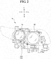
- Fig. 2 is a front view when the vehicle lamp of the embodiment is seen from the vehicular front side, in which a portion at which the outer lens is position is indicated by the double-dotted diagonal line, and shows a light source unit 10 while the housing and the outer lens are omitted. It is to be noted that, in Fig. 2 , the right side is a vehicular central side, and the left side is a vehicular outside.
- the light source unit 10 has: a heat sink 20; and a non-spherical lens 30 and a cylindrical lens 40 which are mounted to the heat sink 20 via a lens holder.
- Fig. 3 is a top view in a case where the light source unit 10 is seen from the vehicular upper side. As shown in Fig. 3 , the light source unit 10 is equipped with: a first light source 50a which is mounted to the heat sink 20 and is provided at the vehicular central side; and a second light source 50b which is provided at the vehicular outside.
- the light source unit 10 is equipped with: a first reflector 60a formed in a shape of a semicircular dome, which is disposed to oppose to the first light source 50a so as to cover the vehicular upper side of the first light source 50a; and a second reflector 60b formed in a shape of a semicircular dome, which is disposed to oppose to the second light source 50b so as to the vehicular upper side of the second light source 50b.
- Light from the first light source 50a is reflected to the non-spherical lens 30 so as to be a focusing light distribution pattern of a low beam light distribution pattern, for example, by the first reflector 60a, and then, the reflected beam is radiated to the vehicular front side via the non-spherical lens 30.
- light from the second light source 50b is reflected to the cylindrical lens 40 so as to be a diffusive light distribution pattern of a lower beam light distribution pattern, for example, by the second reflector 60b, and then, the reflected beam is radiated to the vehicular front side via the cylindrical lens 40.
- the focusing light distribution pattern and diffusive light distribution pattern are multiplexed with each other, and a low beam light distribution pattern is thereby formed.
- the light distribution pattern that is formed by the vehicle lamp of the present invention is not limitative to the low beam light distribution pattern, and may be a pattern to form a high beam light distribution pattern.
- the lens is not limitative to the non-spherical lens 30 and the cylindrical lens 40, and may be appropriately changed to another lens.
- a semiconductor-type light source is employed for each of the first light source 50a and the second light source 50b.
- self-emission semiconductor-type light emitting elements 52, 54 such as an LED or an EL (an organic EL), for example, are respectively implemented on boards 51, 53 on which a power supply pattern or the like, although not shown, has been formed.
- the number and shape of the semiconductor-type light emitting elements 52, 54 that are employed to form a light emitting portion are not limitative in particular, and for example, it may be that a plurality of semiconductor-type light emitting elements 52, 54 formed in a square shape are arrayed on the board 51, 53 in a horizontal direction so as to form a light emission surface formed in a planar rectangular shape as a whole, or alternatively, only one semiconductor-type light emitting element 52, 54 formed in a square shape or in a rectangular shape is provided so as to form a light emission surface.
- the semiconductor-type light emitting elements 52, 54 may be packaged by being sealed with a sealing resin.
- the heat sink 20 is made of a metal member or a resin member of which thermal conductivity is high, and in the embodiment, the heat sink is made of an aluminum die cast.
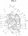
- Fig. 4 is a perspective view in a case where the light source unit 10 is seen from the vehicular central side. As shown in Fig. 4 , the heat sink 20 is equipped with: a base part 21 on which the first light source 50a and the second light source 50b are to be placed a plurality of heat radiation fins 23 which are provided at the vehicular upper side of the base part 21; and a heat radiation fin 23D which is provided on a face 21b (a back face) opposite to a face 21a (a surface) on which the first light source 50a and the second light source 50b of the base part 21 are to be placed.
- the heat radiation fin 23D is formed so that one end thereof connects to the back face of the base part and extends to the vehicular lower side.
- Fig. 5 is a bottom view in a case where the light source unit 10 is seen from the vehicular lower side. As shown in Fig. 5 , the heat radiation fin 23D is provided in plurality so as to be arranged in the vehicular widthwise direction.
- the heat radiation fins 23U are formed toward the vehicular front side from a longitudinal wall 23W which extends from a rear end of the base part 21 (a vehicular end part) towards the vehicular upper side). It is to be noted that, although not shown in Fig. 4 , a lower part of each of the heat radiation fins 23U connects to the base part 21.
- a lens holder 35 is provided at the vehicular front side of the heat sink 20, and the non-spherical lens 30 and the cylindrical lens 40 are mounted to the lens holder 35 by a retainer 31 and a retainer 41, respectively.
- the straight line L of the double-dotted diagonal line shown in Fig. 3 indicates a straight line which connects the semiconductor-type light emitting element 52 of the first light source 50a and the semiconductor-type light emitting element 54 of the second light source 50b to each other.
- a route in which the largest amount of the heat is to be transmitted from one light source (for example, the first light source 50a) side to the other light source (for example, the second light source 50b) side as has been described hereinabove is the shortest route that is indicated by the straight line L.
- a through hole 28 which penetrates the base part 21 is formed, and heat transmission in the shortest route is thereby restrained, and the temperature rise of the light source (the first light source 50a, the second light source 50b) is restrained, and lowering of the light emission efficiency is thereby restrained.
- the base part 21 is formed in a stepped shape which is provided with: a first light source mounting surface 25a for mounting the first light source 50a; a second mounting mounting surface 25b for mounting the second light source 50b which is provided so as to be higher by one step so as to be positioned at the vehicular outside more significantly than the first light source mounting surface 25a and at the vehicular upper side; and a longitudinal wall surface 25c which connects the first light source mounting surface 25a and the second light source mounting surface 25b to each other.
- the through hole 28, a part of which is not shown in Fig. 4 , is formed all over the first light source mounting surface 25a from the longitudinal wall surface 25c.
- the embodiment shows the case in which the through hole 28 is formed all over the first light source mounting surface 25a from the longitudinal wall surface 25c, without being limitative thereto, for example, it may be the through hole 28 is formed from the first light source mounting surface 25a up to the second light source mounting surface 25b via the longitudinal wall surface 25c and then the through hole 28 is formed so as to overhang the stepped shape.
- the through hole 28 is provided at a position between screws for fixing the first reflector 60a and the second reflector 60b to each other.
- the first reflector 60a is fixed to the base part 21 with screws 70 at two positions which are a position at the vehicular central side and a position at the vehicular outside.
- first screw fastening parts for fastening the first reflector 60a with screws are formed.
- the second reflector 60b is also fixed to the base part 21 with screws 75 at two positions which are a position at the vehicular central side and at a position at the vehicular outside, and at the positions of the base part 21, which correspond to the positions of the screws 75 shown in Fig. 3 , second screw fastening parts for fastening the second reflector 60b with screws are formed.
- the through hole 28 is formed at a position between a first screw fastening part which is positioned at the second reflector 60b, of the two first screw fastening parts that are provided at the base part 21 for fixing the first reflector 60a; and a second screw fastening part which is positioned at the first reflector 60a side, of the two second screw fastening parts that are provided at the base part 21 for fixing the second reflector 60b.
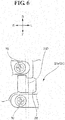
- Fig. 6 is an enlarged view of the portion E of Fig. 3 , namely is an enlarged view of the periphery of the through hole 28.
- Fig. 6 and Fig. 5 which is a bottom view in a case where the light source unit 10 is seen from the vehicular lower side, one of the plurality of heat radiation fins 23D that are provided on the back face (the face 21b) of the base part 21 is provided so as to overhang the through hole 28 in the vehicular forward and backward directions.
- the number of heat radiation fins 23D that are provided so as to overhang the through hole 28 may be in plurality without being limitative to only one, and it may be that no heat radiation fin 23D is provided so as to overhang the through hole 28. However, as described later, it is preferable to provide the heat radiation fins 23D so as to overhang the through hole 28.
- the through hole 28 that penetrates the base part 21 is provided at the position on the straight line L (on the shortest route) that connects the first light source 50a and the second light source 50b to each other. Therefore, an occurrence of heat transmission between the light sources (the first light source 50a, the second light source 50b) via the shortest route is restrained, thus making it possible to reduce the quantity of the heat that is transmitted from one light source to the other light source.
- Fig. 7 is a sectional view taken along the line C shown in Fig. 3 .
- the rising airflow arises, as indicated by the arrow in Fig. 7 , a fresh air flows from the vehicular lower side into the through hole 28, as it were drawn by the rising airflow; and therefore, the periphery of the through hole 28 is effectively cooled.
- the position at which the through hole 28 is provided is present on the shortest route between the light sources (the first light source 50a, the second light source 50b) and thus it is possible to cool is a position at which the heat is most likely to gather, and the position at which the heat is most likely to gather; and therefore, the heat radiation effect is enhanced.
- the heat radiation fins 23D are also provided so as to overhang the through hole 28, and by the heat radiation fins 23D, the heat radiation effect is further enhanced, and moreover, as described above, at this portion, the airflow is formed; and therefore, the heat radiation effect of the heat radiation fins 23D is more remarkably enhanced.
- the through hole 28 is provided between the first screw fastening parts at which the screws 70 for fixing the first reflector 60a are provided and the second screw fastening parts at which the screws 75 fixing the second reflector 60b therewith are provided; and therefore, these screw fastening parts (the first screw fastening parts, the second screw fastening parts) are also cooled due to the airflow that passes through the through hole 28. Therefore, looseness or the like of the screws 70, 75, which may occur under the influence of thermal expansion or the like, is also restrained.
- the second light source mounting surface 25b is positioned at the vehicular upper side more significantly than the first light source mounting surface 25a, and the shape (the stepped shape) that is provided with the longitudinal wall surface 25c to connect the first light source mounting surface 25a and the second light source mounting surface 25b to each other is formed.
- the first light source mounting surface 25a and the second light source mounting surface 25b are set at the same position at the same height at the vehicular upper side, and the first light source mounting surface 25a and the second light source mounting surface 25b connect to each other on a face-to-face basis, a distance of heat transmission from one light source (for example, the first light source 50a) to the other light source (for example, the second light source 50b) is increased by the longitudinal wall surface 25c thus provided; and hence, the heat is hardly transmitted.
- the longitudinal wall surface 25c In the longitudinal wall surface 25c, the through hole 28 through which air flows is provided, and a part of the air that flows the through hole 28 also flows along the longitudinal wall surface 25c at the periphery of the through hole 28; and therefore, the longitudinal wall surface 25c per se attains an advantageous effect similar to that of the heat radiation of which cooling efficiency is good, and heat transmission between the light sources (the first light source 50a, the second light source 50b) is more remarkably restrained.
- the through hole 28 was merely formed at a part of the shortest route on which the heat is most likely to be transmitted and thus lowering of the rigidity of the heat sink 20 is restrained. Moreover, the heat radiation fins 23D that have been provided so as to overhang the through hole 28 also attains an advantageous effect of a reinforcement rib. In addition, the through hole 28 was formed, making it possible to reduce the weight of the heat sink 20, accordingly.
- heat radiation on the shortest route on which the heat is most likely to be transmitted can be carried out to thereby conversely enable a design modification such as reduction of a heat radiation fin of which heat radiation efficiency is low at a position which is distant from the light sources (the first light source 50a, the second light source 50b) of the heat sink 20, making it possible to reduce the weight of the heat sink 20, and due to this reduction, making it also possible to reduce the size of the heat sink 20 per se.
Landscapes
- Engineering & Computer Science (AREA)
- General Engineering & Computer Science (AREA)
- Physics & Mathematics (AREA)
- Microelectronics & Electronic Packaging (AREA)
- Optics & Photonics (AREA)
- Non-Portable Lighting Devices Or Systems Thereof (AREA)
- Arrangement Of Elements, Cooling, Sealing, Or The Like Of Lighting Devices (AREA)
Applications Claiming Priority (2)
| Application Number | Priority Date | Filing Date | Title |
|---|---|---|---|
| JP2014096087A JP2015215944A (ja) | 2014-05-07 | 2014-05-07 | 車両用灯具 |
| PCT/JP2015/061248 WO2015170552A1 (fr) | 2014-05-07 | 2015-04-10 | Feu de véhicule |
Publications (3)
| Publication Number | Publication Date |
|---|---|
| EP3141800A1 true EP3141800A1 (fr) | 2017-03-15 |
| EP3141800A4 EP3141800A4 (fr) | 2018-01-03 |
| EP3141800B1 EP3141800B1 (fr) | 2021-01-20 |
Family
ID=54392405
Family Applications (1)
| Application Number | Title | Priority Date | Filing Date |
|---|---|---|---|
| EP15788970.0A Active EP3141800B1 (fr) | 2014-05-07 | 2015-04-10 | Feu de véhicule |
Country Status (5)
| Country | Link |
|---|---|
| US (1) | US20170074480A1 (fr) |
| EP (1) | EP3141800B1 (fr) |
| JP (1) | JP2015215944A (fr) |
| CN (1) | CN106255853B (fr) |
| WO (1) | WO2015170552A1 (fr) |
Families Citing this family (2)
| Publication number | Priority date | Publication date | Assignee | Title |
|---|---|---|---|---|
| JP2019175680A (ja) * | 2018-03-28 | 2019-10-10 | 市光工業株式会社 | 車両用灯具 |
| DE102018133061A1 (de) * | 2018-12-20 | 2020-06-25 | HELLA GmbH & Co. KGaA | Linsenhalter zur Aufnahme einer Linse in einem Scheinwerfer |
Family Cites Families (12)
| Publication number | Priority date | Publication date | Assignee | Title |
|---|---|---|---|---|
| JP4595781B2 (ja) * | 2005-10-17 | 2010-12-08 | 市光工業株式会社 | 車両用灯具 |
| JP2008257959A (ja) * | 2007-04-03 | 2008-10-23 | Koito Mfg Co Ltd | 車両用灯具 |
| JP2009140718A (ja) * | 2007-12-05 | 2009-06-25 | Toshiba Lighting & Technology Corp | 照明装置 |
| FR2938316B1 (fr) * | 2008-11-12 | 2013-09-13 | Valeo Vision Sas | Dissipateur de chaleur monobloc pour modules optiques d'un dispositif d'eclairage et/ou de signalisation de vehicule automobile |
| JP5231194B2 (ja) * | 2008-12-17 | 2013-07-10 | 株式会社小糸製作所 | 車両用灯具 |
| JP2010165537A (ja) * | 2009-01-15 | 2010-07-29 | Ichikoh Ind Ltd | 車両用灯具 |
| JP5287324B2 (ja) * | 2009-02-13 | 2013-09-11 | 市光工業株式会社 | 車両用灯具 |
| JP2010238604A (ja) * | 2009-03-31 | 2010-10-21 | Koito Mfg Co Ltd | 発光素子モジュール化部材および灯具ユニット |
| JP2011028963A (ja) * | 2009-07-24 | 2011-02-10 | Stanley Electric Co Ltd | 車両用灯具 |
| US8932282B2 (en) * | 2009-08-03 | 2015-01-13 | Covidien Lp | Power level transitioning in a surgical instrument |
| FR2982006B1 (fr) * | 2011-09-13 | 2018-04-27 | Valeo Vision | Module optique a reference commune, pour eclairage et/ou signalisation d'un vehicule automobile |
| JP2014013663A (ja) * | 2012-07-03 | 2014-01-23 | Honda Motor Co Ltd | 車両のled灯火器 |
-
2014
- 2014-05-07 JP JP2014096087A patent/JP2015215944A/ja active Pending
-
2015
- 2015-04-10 US US15/309,069 patent/US20170074480A1/en not_active Abandoned
- 2015-04-10 CN CN201580022428.9A patent/CN106255853B/zh active Active
- 2015-04-10 WO PCT/JP2015/061248 patent/WO2015170552A1/fr not_active Ceased
- 2015-04-10 EP EP15788970.0A patent/EP3141800B1/fr active Active
Also Published As
| Publication number | Publication date |
|---|---|
| EP3141800A4 (fr) | 2018-01-03 |
| WO2015170552A1 (fr) | 2015-11-12 |
| CN106255853B (zh) | 2019-03-26 |
| JP2015215944A (ja) | 2015-12-03 |
| US20170074480A1 (en) | 2017-03-16 |
| CN106255853A (zh) | 2016-12-21 |
| EP3141800B1 (fr) | 2021-01-20 |
Similar Documents
| Publication | Publication Date | Title |
|---|---|---|
| EP3180968B1 (fr) | Appareil d'éclairage à del à réseau cadre ouvert de modules lumineux | |
| CN105180049B (zh) | 用于汽车前照灯的光学模块 | |
| EP2112427A1 (fr) | Lampe de véhicule | |
| JP2015164121A (ja) | 光源ユニット | |
| EP2123974A2 (fr) | Lampe de véhicule | |
| JP6283357B2 (ja) | 車両用灯具 | |
| US9857047B2 (en) | Cooling member and motor vehicle lighting or signaling device comprising such a member | |
| EP3141800B1 (fr) | Feu de véhicule | |
| EP3290789A1 (fr) | Luminaire comprenant une structure de dissipation de chaleur | |
| JP5950112B2 (ja) | 自動二輪車用ヘッドランプ | |
| JP6442871B2 (ja) | 車両用灯具 | |
| JP6536101B2 (ja) | 車両用灯具 | |
| JP6287431B2 (ja) | 車両用灯具 | |
| JP6518545B2 (ja) | Led照明用放熱装置 | |
| JP6061071B2 (ja) | 自動二輪車用ヘッドランプ | |
| JP6397339B2 (ja) | Led照明用放熱装置 | |
| EP2997296B1 (fr) | Refroidissement à l'air d'un pilote électronique dans un dispositif d'éclairage | |
| JP2014065339A (ja) | 自動二輪車用ヘッドランプ | |
| JP5962990B2 (ja) | 自動二輪車用ヘッドランプ | |
| JP6476663B2 (ja) | 車両用灯具 | |
| CN217584369U (zh) | 灯具散热装置及具有其的照明灯具 | |
| KR20160015758A (ko) | 차량용 램프 | |
| JP2024180062A (ja) | 車両用灯具 | |
| JP2014067495A (ja) | 自動二輪車用ヘッドランプ | |
| JP2016162573A (ja) | 埋込型照明器具 |
Legal Events
| Date | Code | Title | Description |
|---|---|---|---|
| STAA | Information on the status of an ep patent application or granted ep patent |
Free format text: STATUS: THE INTERNATIONAL PUBLICATION HAS BEEN MADE |
|
| PUAI | Public reference made under article 153(3) epc to a published international application that has entered the european phase |
Free format text: ORIGINAL CODE: 0009012 |
|
| STAA | Information on the status of an ep patent application or granted ep patent |
Free format text: STATUS: REQUEST FOR EXAMINATION WAS MADE |
|
| 17P | Request for examination filed |
Effective date: 20161107 |
|
| AK | Designated contracting states |
Kind code of ref document: A1 Designated state(s): AL AT BE BG CH CY CZ DE DK EE ES FI FR GB GR HR HU IE IS IT LI LT LU LV MC MK MT NL NO PL PT RO RS SE SI SK SM TR |
|
| AX | Request for extension of the european patent |
Extension state: BA ME |
|
| DAV | Request for validation of the european patent (deleted) | ||
| DAX | Request for extension of the european patent (deleted) | ||
| RIN1 | Information on inventor provided before grant (corrected) |
Inventor name: SUZUKI, EIJI Inventor name: TOMITA, SHINOBU |
|
| A4 | Supplementary search report drawn up and despatched |
Effective date: 20171206 |
|
| RIC1 | Information provided on ipc code assigned before grant |
Ipc: F21V 29/15 20150101ALI20171130BHEP Ipc: F21S 8/10 00000000AFI20171130BHEP Ipc: F21V 29/76 20150101ALI20171130BHEP Ipc: F21W 101/10 00000000ALI20171130BHEP Ipc: F21V 29/83 20150101ALI20171130BHEP Ipc: F21V 29/503 20150101ALI20171130BHEP |
|
| RIC1 | Information provided on ipc code assigned before grant |
Ipc: F21S 8/10 20060101AFI20171130BHEP Ipc: F21V 29/76 20150101ALI20171130BHEP Ipc: F21V 29/503 20150101ALI20171130BHEP Ipc: F21V 29/15 20150101ALI20171130BHEP Ipc: F21W 101/10 20060101ALI20171130BHEP Ipc: F21V 29/83 20150101ALI20171130BHEP |
|
| RIC1 | Information provided on ipc code assigned before grant |
Ipc: F21S 41/147 20180101AFI20200218BHEP Ipc: F21S 41/32 20180101ALI20200218BHEP Ipc: F21S 41/29 20180101ALI20200218BHEP Ipc: F21S 41/255 20180101ALN20200218BHEP Ipc: F21S 41/39 20180101ALI20200218BHEP Ipc: F21S 45/47 20180101ALI20200218BHEP Ipc: F21S 41/26 20180101ALN20200218BHEP |
|
| REG | Reference to a national code |
Ref country code: DE Ref legal event code: R079 Ref document number: 602015064986 Country of ref document: DE Free format text: PREVIOUS MAIN CLASS: F21S0008100000 Ipc: F21S0041147000 |
|
| RIC1 | Information provided on ipc code assigned before grant |
Ipc: F21S 41/255 20180101ALN20200610BHEP Ipc: F21S 41/29 20180101ALI20200610BHEP Ipc: F21S 45/47 20180101ALI20200610BHEP Ipc: F21S 41/32 20180101ALI20200610BHEP Ipc: F21S 41/148 20180101ALI20200610BHEP Ipc: F21S 45/48 20180101ALI20200610BHEP Ipc: F21S 41/147 20180101AFI20200610BHEP Ipc: F21S 41/39 20180101ALI20200610BHEP Ipc: F21S 41/26 20180101ALN20200610BHEP |
|
| RIC1 | Information provided on ipc code assigned before grant |
Ipc: F21S 41/148 20180101ALI20200622BHEP Ipc: F21S 41/32 20180101ALI20200622BHEP Ipc: F21S 45/48 20180101ALI20200622BHEP Ipc: F21S 41/29 20180101ALI20200622BHEP Ipc: F21S 41/26 20180101ALN20200622BHEP Ipc: F21S 41/147 20180101AFI20200622BHEP Ipc: F21S 41/39 20180101ALI20200622BHEP Ipc: F21S 45/47 20180101ALI20200622BHEP Ipc: F21S 41/255 20180101ALN20200622BHEP |
|
| GRAP | Despatch of communication of intention to grant a patent |
Free format text: ORIGINAL CODE: EPIDOSNIGR1 |
|
| STAA | Information on the status of an ep patent application or granted ep patent |
Free format text: STATUS: GRANT OF PATENT IS INTENDED |
|
| INTG | Intention to grant announced |
Effective date: 20200914 |
|
| GRAS | Grant fee paid |
Free format text: ORIGINAL CODE: EPIDOSNIGR3 |
|
| GRAA | (expected) grant |
Free format text: ORIGINAL CODE: 0009210 |
|
| STAA | Information on the status of an ep patent application or granted ep patent |
Free format text: STATUS: THE PATENT HAS BEEN GRANTED |
|
| AK | Designated contracting states |
Kind code of ref document: B1 Designated state(s): AL AT BE BG CH CY CZ DE DK EE ES FI FR GB GR HR HU IE IS IT LI LT LU LV MC MK MT NL NO PL PT RO RS SE SI SK SM TR |
|
| REG | Reference to a national code |
Ref country code: GB Ref legal event code: FG4D |
|
| REG | Reference to a national code |
Ref country code: CH Ref legal event code: EP |
|
| REG | Reference to a national code |
Ref country code: DE Ref legal event code: R096 Ref document number: 602015064986 Country of ref document: DE |
|
| REG | Reference to a national code |
Ref country code: AT Ref legal event code: REF Ref document number: 1356718 Country of ref document: AT Kind code of ref document: T Effective date: 20210215 |
|
| REG | Reference to a national code |
Ref country code: IE Ref legal event code: FG4D |
|
| REG | Reference to a national code |
Ref country code: NL Ref legal event code: MP Effective date: 20210120 |
|
| REG | Reference to a national code |
Ref country code: LT Ref legal event code: MG9D |
|
| REG | Reference to a national code |
Ref country code: AT Ref legal event code: MK05 Ref document number: 1356718 Country of ref document: AT Kind code of ref document: T Effective date: 20210120 |
|
| PG25 | Lapsed in a contracting state [announced via postgrant information from national office to epo] |
Ref country code: HR Free format text: LAPSE BECAUSE OF FAILURE TO SUBMIT A TRANSLATION OF THE DESCRIPTION OR TO PAY THE FEE WITHIN THE PRESCRIBED TIME-LIMIT Effective date: 20210120 Ref country code: GR Free format text: LAPSE BECAUSE OF FAILURE TO SUBMIT A TRANSLATION OF THE DESCRIPTION OR TO PAY THE FEE WITHIN THE PRESCRIBED TIME-LIMIT Effective date: 20210421 Ref country code: FI Free format text: LAPSE BECAUSE OF FAILURE TO SUBMIT A TRANSLATION OF THE DESCRIPTION OR TO PAY THE FEE WITHIN THE PRESCRIBED TIME-LIMIT Effective date: 20210120 Ref country code: NO Free format text: LAPSE BECAUSE OF FAILURE TO SUBMIT A TRANSLATION OF THE DESCRIPTION OR TO PAY THE FEE WITHIN THE PRESCRIBED TIME-LIMIT Effective date: 20210420 Ref country code: NL Free format text: LAPSE BECAUSE OF FAILURE TO SUBMIT A TRANSLATION OF THE DESCRIPTION OR TO PAY THE FEE WITHIN THE PRESCRIBED TIME-LIMIT Effective date: 20210120 Ref country code: BG Free format text: LAPSE BECAUSE OF FAILURE TO SUBMIT A TRANSLATION OF THE DESCRIPTION OR TO PAY THE FEE WITHIN THE PRESCRIBED TIME-LIMIT Effective date: 20210420 Ref country code: LT Free format text: LAPSE BECAUSE OF FAILURE TO SUBMIT A TRANSLATION OF THE DESCRIPTION OR TO PAY THE FEE WITHIN THE PRESCRIBED TIME-LIMIT Effective date: 20210120 Ref country code: PT Free format text: LAPSE BECAUSE OF FAILURE TO SUBMIT A TRANSLATION OF THE DESCRIPTION OR TO PAY THE FEE WITHIN THE PRESCRIBED TIME-LIMIT Effective date: 20210520 |
|
| PG25 | Lapsed in a contracting state [announced via postgrant information from national office to epo] |
Ref country code: SE Free format text: LAPSE BECAUSE OF FAILURE TO SUBMIT A TRANSLATION OF THE DESCRIPTION OR TO PAY THE FEE WITHIN THE PRESCRIBED TIME-LIMIT Effective date: 20210120 Ref country code: AT Free format text: LAPSE BECAUSE OF FAILURE TO SUBMIT A TRANSLATION OF THE DESCRIPTION OR TO PAY THE FEE WITHIN THE PRESCRIBED TIME-LIMIT Effective date: 20210120 Ref country code: RS Free format text: LAPSE BECAUSE OF FAILURE TO SUBMIT A TRANSLATION OF THE DESCRIPTION OR TO PAY THE FEE WITHIN THE PRESCRIBED TIME-LIMIT Effective date: 20210120 Ref country code: LV Free format text: LAPSE BECAUSE OF FAILURE TO SUBMIT A TRANSLATION OF THE DESCRIPTION OR TO PAY THE FEE WITHIN THE PRESCRIBED TIME-LIMIT Effective date: 20210120 Ref country code: PL Free format text: LAPSE BECAUSE OF FAILURE TO SUBMIT A TRANSLATION OF THE DESCRIPTION OR TO PAY THE FEE WITHIN THE PRESCRIBED TIME-LIMIT Effective date: 20210120 |
|
| PG25 | Lapsed in a contracting state [announced via postgrant information from national office to epo] |
Ref country code: IS Free format text: LAPSE BECAUSE OF FAILURE TO SUBMIT A TRANSLATION OF THE DESCRIPTION OR TO PAY THE FEE WITHIN THE PRESCRIBED TIME-LIMIT Effective date: 20210520 |
|
| REG | Reference to a national code |
Ref country code: DE Ref legal event code: R097 Ref document number: 602015064986 Country of ref document: DE |
|
| PG25 | Lapsed in a contracting state [announced via postgrant information from national office to epo] |
Ref country code: SM Free format text: LAPSE BECAUSE OF FAILURE TO SUBMIT A TRANSLATION OF THE DESCRIPTION OR TO PAY THE FEE WITHIN THE PRESCRIBED TIME-LIMIT Effective date: 20210120 Ref country code: CZ Free format text: LAPSE BECAUSE OF FAILURE TO SUBMIT A TRANSLATION OF THE DESCRIPTION OR TO PAY THE FEE WITHIN THE PRESCRIBED TIME-LIMIT Effective date: 20210120 Ref country code: EE Free format text: LAPSE BECAUSE OF FAILURE TO SUBMIT A TRANSLATION OF THE DESCRIPTION OR TO PAY THE FEE WITHIN THE PRESCRIBED TIME-LIMIT Effective date: 20210120 |
|
| PLBE | No opposition filed within time limit |
Free format text: ORIGINAL CODE: 0009261 |
|
| STAA | Information on the status of an ep patent application or granted ep patent |
Free format text: STATUS: NO OPPOSITION FILED WITHIN TIME LIMIT |
|
| PG25 | Lapsed in a contracting state [announced via postgrant information from national office to epo] |
Ref country code: SK Free format text: LAPSE BECAUSE OF FAILURE TO SUBMIT A TRANSLATION OF THE DESCRIPTION OR TO PAY THE FEE WITHIN THE PRESCRIBED TIME-LIMIT Effective date: 20210120 Ref country code: RO Free format text: LAPSE BECAUSE OF FAILURE TO SUBMIT A TRANSLATION OF THE DESCRIPTION OR TO PAY THE FEE WITHIN THE PRESCRIBED TIME-LIMIT Effective date: 20210120 Ref country code: ES Free format text: LAPSE BECAUSE OF FAILURE TO SUBMIT A TRANSLATION OF THE DESCRIPTION OR TO PAY THE FEE WITHIN THE PRESCRIBED TIME-LIMIT Effective date: 20210120 Ref country code: DK Free format text: LAPSE BECAUSE OF FAILURE TO SUBMIT A TRANSLATION OF THE DESCRIPTION OR TO PAY THE FEE WITHIN THE PRESCRIBED TIME-LIMIT Effective date: 20210120 Ref country code: MC Free format text: LAPSE BECAUSE OF FAILURE TO SUBMIT A TRANSLATION OF THE DESCRIPTION OR TO PAY THE FEE WITHIN THE PRESCRIBED TIME-LIMIT Effective date: 20210120 |
|
| 26N | No opposition filed |
Effective date: 20211021 |
|
| PG25 | Lapsed in a contracting state [announced via postgrant information from national office to epo] |
Ref country code: LU Free format text: LAPSE BECAUSE OF NON-PAYMENT OF DUE FEES Effective date: 20210410 |
|
| REG | Reference to a national code |
Ref country code: BE Ref legal event code: MM Effective date: 20210430 |
|
| PG25 | Lapsed in a contracting state [announced via postgrant information from national office to epo] |
Ref country code: CH Free format text: LAPSE BECAUSE OF NON-PAYMENT OF DUE FEES Effective date: 20210430 Ref country code: AL Free format text: LAPSE BECAUSE OF FAILURE TO SUBMIT A TRANSLATION OF THE DESCRIPTION OR TO PAY THE FEE WITHIN THE PRESCRIBED TIME-LIMIT Effective date: 20210120 Ref country code: LI Free format text: LAPSE BECAUSE OF NON-PAYMENT OF DUE FEES Effective date: 20210430 |
|
| PG25 | Lapsed in a contracting state [announced via postgrant information from national office to epo] |
Ref country code: SI Free format text: LAPSE BECAUSE OF FAILURE TO SUBMIT A TRANSLATION OF THE DESCRIPTION OR TO PAY THE FEE WITHIN THE PRESCRIBED TIME-LIMIT Effective date: 20210120 |
|
| PG25 | Lapsed in a contracting state [announced via postgrant information from national office to epo] |
Ref country code: IT Free format text: LAPSE BECAUSE OF FAILURE TO SUBMIT A TRANSLATION OF THE DESCRIPTION OR TO PAY THE FEE WITHIN THE PRESCRIBED TIME-LIMIT Effective date: 20210120 Ref country code: IE Free format text: LAPSE BECAUSE OF NON-PAYMENT OF DUE FEES Effective date: 20210410 |
|
| PG25 | Lapsed in a contracting state [announced via postgrant information from national office to epo] |
Ref country code: IS Free format text: LAPSE BECAUSE OF FAILURE TO SUBMIT A TRANSLATION OF THE DESCRIPTION OR TO PAY THE FEE WITHIN THE PRESCRIBED TIME-LIMIT Effective date: 20210520 |
|
| PG25 | Lapsed in a contracting state [announced via postgrant information from national office to epo] |
Ref country code: BE Free format text: LAPSE BECAUSE OF NON-PAYMENT OF DUE FEES Effective date: 20210430 |
|
| PG25 | Lapsed in a contracting state [announced via postgrant information from national office to epo] |
Ref country code: HU Free format text: LAPSE BECAUSE OF FAILURE TO SUBMIT A TRANSLATION OF THE DESCRIPTION OR TO PAY THE FEE WITHIN THE PRESCRIBED TIME-LIMIT; INVALID AB INITIO Effective date: 20150410 |
|
| PG25 | Lapsed in a contracting state [announced via postgrant information from national office to epo] |
Ref country code: CY Free format text: LAPSE BECAUSE OF FAILURE TO SUBMIT A TRANSLATION OF THE DESCRIPTION OR TO PAY THE FEE WITHIN THE PRESCRIBED TIME-LIMIT Effective date: 20210120 |
|
| PG25 | Lapsed in a contracting state [announced via postgrant information from national office to epo] |
Ref country code: MK Free format text: LAPSE BECAUSE OF FAILURE TO SUBMIT A TRANSLATION OF THE DESCRIPTION OR TO PAY THE FEE WITHIN THE PRESCRIBED TIME-LIMIT Effective date: 20210120 |
|
| PG25 | Lapsed in a contracting state [announced via postgrant information from national office to epo] |
Ref country code: MT Free format text: LAPSE BECAUSE OF FAILURE TO SUBMIT A TRANSLATION OF THE DESCRIPTION OR TO PAY THE FEE WITHIN THE PRESCRIBED TIME-LIMIT Effective date: 20210120 |
|
| PGFP | Annual fee paid to national office [announced via postgrant information from national office to epo] |
Ref country code: DE Payment date: 20250422 Year of fee payment: 11 |
|
| PGFP | Annual fee paid to national office [announced via postgrant information from national office to epo] |
Ref country code: GB Payment date: 20250423 Year of fee payment: 11 |
|
| PGFP | Annual fee paid to national office [announced via postgrant information from national office to epo] |
Ref country code: FR Payment date: 20250425 Year of fee payment: 11 |
|
| PG25 | Lapsed in a contracting state [announced via postgrant information from national office to epo] |
Ref country code: TR Free format text: LAPSE BECAUSE OF FAILURE TO SUBMIT A TRANSLATION OF THE DESCRIPTION OR TO PAY THE FEE WITHIN THE PRESCRIBED TIME-LIMIT Effective date: 20210120 |