EP3141801A1 - Fahrzeuglampenarmatur - Google Patents
Fahrzeuglampenarmatur Download PDFInfo
- Publication number
- EP3141801A1 EP3141801A1 EP15789813.1A EP15789813A EP3141801A1 EP 3141801 A1 EP3141801 A1 EP 3141801A1 EP 15789813 A EP15789813 A EP 15789813A EP 3141801 A1 EP3141801 A1 EP 3141801A1
- Authority
- EP
- European Patent Office
- Prior art keywords
- vehicular
- reflector
- guide member
- light guide
- light
- Prior art date
- Legal status (The legal status is an assumption and is not a legal conclusion. Google has not performed a legal analysis and makes no representation as to the accuracy of the status listed.)
- Granted
Links
Images


Classifications
-
- F—MECHANICAL ENGINEERING; LIGHTING; HEATING; WEAPONS; BLASTING
- F21—LIGHTING
- F21S—NON-PORTABLE LIGHTING DEVICES; SYSTEMS THEREOF; VEHICLE LIGHTING DEVICES SPECIALLY ADAPTED FOR VEHICLE EXTERIORS
- F21S43/00—Signalling devices specially adapted for vehicle exteriors, e.g. brake lamps, direction indicator lights or reversing lights
- F21S43/40—Signalling devices specially adapted for vehicle exteriors, e.g. brake lamps, direction indicator lights or reversing lights characterised by the combination of reflectors and refractors
-
- F—MECHANICAL ENGINEERING; LIGHTING; HEATING; WEAPONS; BLASTING
- F21—LIGHTING
- F21S—NON-PORTABLE LIGHTING DEVICES; SYSTEMS THEREOF; VEHICLE LIGHTING DEVICES SPECIALLY ADAPTED FOR VEHICLE EXTERIORS
- F21S41/00—Illuminating devices specially adapted for vehicle exteriors, e.g. headlamps
- F21S41/10—Illuminating devices specially adapted for vehicle exteriors, e.g. headlamps characterised by the light source
- F21S41/14—Illuminating devices specially adapted for vehicle exteriors, e.g. headlamps characterised by the light source characterised by the type of light source
- F21S41/141—Light emitting diodes [LED]
-
- F—MECHANICAL ENGINEERING; LIGHTING; HEATING; WEAPONS; BLASTING
- F21—LIGHTING
- F21S—NON-PORTABLE LIGHTING DEVICES; SYSTEMS THEREOF; VEHICLE LIGHTING DEVICES SPECIALLY ADAPTED FOR VEHICLE EXTERIORS
- F21S41/00—Illuminating devices specially adapted for vehicle exteriors, e.g. headlamps
- F21S41/20—Illuminating devices specially adapted for vehicle exteriors, e.g. headlamps characterised by refractors, transparent cover plates, light guides or filters
- F21S41/24—Light guides
-
- F—MECHANICAL ENGINEERING; LIGHTING; HEATING; WEAPONS; BLASTING
- F21—LIGHTING
- F21S—NON-PORTABLE LIGHTING DEVICES; SYSTEMS THEREOF; VEHICLE LIGHTING DEVICES SPECIALLY ADAPTED FOR VEHICLE EXTERIORS
- F21S41/00—Illuminating devices specially adapted for vehicle exteriors, e.g. headlamps
- F21S41/20—Illuminating devices specially adapted for vehicle exteriors, e.g. headlamps characterised by refractors, transparent cover plates, light guides or filters
- F21S41/2805—Cover glass
-
- F—MECHANICAL ENGINEERING; LIGHTING; HEATING; WEAPONS; BLASTING
- F21—LIGHTING
- F21S—NON-PORTABLE LIGHTING DEVICES; SYSTEMS THEREOF; VEHICLE LIGHTING DEVICES SPECIALLY ADAPTED FOR VEHICLE EXTERIORS
- F21S41/00—Illuminating devices specially adapted for vehicle exteriors, e.g. headlamps
- F21S41/30—Illuminating devices specially adapted for vehicle exteriors, e.g. headlamps characterised by reflectors
- F21S41/32—Optical layout thereof
- F21S41/33—Multi-surface reflectors, e.g. reflectors with facets or reflectors with portions of different curvature
- F21S41/334—Multi-surface reflectors, e.g. reflectors with facets or reflectors with portions of different curvature the reflector consisting of patch like sectors
- F21S41/335—Multi-surface reflectors, e.g. reflectors with facets or reflectors with portions of different curvature the reflector consisting of patch like sectors with continuity at the junction between adjacent areas
-
- F—MECHANICAL ENGINEERING; LIGHTING; HEATING; WEAPONS; BLASTING
- F21—LIGHTING
- F21S—NON-PORTABLE LIGHTING DEVICES; SYSTEMS THEREOF; VEHICLE LIGHTING DEVICES SPECIALLY ADAPTED FOR VEHICLE EXTERIORS
- F21S43/00—Signalling devices specially adapted for vehicle exteriors, e.g. brake lamps, direction indicator lights or reversing lights
- F21S43/10—Signalling devices specially adapted for vehicle exteriors, e.g. brake lamps, direction indicator lights or reversing lights characterised by the light source
- F21S43/13—Signalling devices specially adapted for vehicle exteriors, e.g. brake lamps, direction indicator lights or reversing lights characterised by the light source characterised by the type of light source
- F21S43/14—Light emitting diodes [LED]
-
- F—MECHANICAL ENGINEERING; LIGHTING; HEATING; WEAPONS; BLASTING
- F21—LIGHTING
- F21S—NON-PORTABLE LIGHTING DEVICES; SYSTEMS THEREOF; VEHICLE LIGHTING DEVICES SPECIALLY ADAPTED FOR VEHICLE EXTERIORS
- F21S43/00—Signalling devices specially adapted for vehicle exteriors, e.g. brake lamps, direction indicator lights or reversing lights
- F21S43/20—Signalling devices specially adapted for vehicle exteriors, e.g. brake lamps, direction indicator lights or reversing lights characterised by refractors, transparent cover plates, light guides or filters
- F21S43/235—Light guides
- F21S43/236—Light guides characterised by the shape of the light guide
- F21S43/237—Light guides characterised by the shape of the light guide rod-shaped
-
- F—MECHANICAL ENGINEERING; LIGHTING; HEATING; WEAPONS; BLASTING
- F21—LIGHTING
- F21S—NON-PORTABLE LIGHTING DEVICES; SYSTEMS THEREOF; VEHICLE LIGHTING DEVICES SPECIALLY ADAPTED FOR VEHICLE EXTERIORS
- F21S43/00—Signalling devices specially adapted for vehicle exteriors, e.g. brake lamps, direction indicator lights or reversing lights
- F21S43/20—Signalling devices specially adapted for vehicle exteriors, e.g. brake lamps, direction indicator lights or reversing lights characterised by refractors, transparent cover plates, light guides or filters
- F21S43/235—Light guides
- F21S43/242—Light guides characterised by the emission area
- F21S43/245—Light guides characterised by the emission area emitting light from one or more of its major surfaces
-
- F—MECHANICAL ENGINEERING; LIGHTING; HEATING; WEAPONS; BLASTING
- F21—LIGHTING
- F21S—NON-PORTABLE LIGHTING DEVICES; SYSTEMS THEREOF; VEHICLE LIGHTING DEVICES SPECIALLY ADAPTED FOR VEHICLE EXTERIORS
- F21S43/00—Signalling devices specially adapted for vehicle exteriors, e.g. brake lamps, direction indicator lights or reversing lights
- F21S43/20—Signalling devices specially adapted for vehicle exteriors, e.g. brake lamps, direction indicator lights or reversing lights characterised by refractors, transparent cover plates, light guides or filters
- F21S43/235—Light guides
- F21S43/242—Light guides characterised by the emission area
- F21S43/246—Light guides characterised by the emission area having two or more output branches
-
- F—MECHANICAL ENGINEERING; LIGHTING; HEATING; WEAPONS; BLASTING
- F21—LIGHTING
- F21S—NON-PORTABLE LIGHTING DEVICES; SYSTEMS THEREOF; VEHICLE LIGHTING DEVICES SPECIALLY ADAPTED FOR VEHICLE EXTERIORS
- F21S43/00—Signalling devices specially adapted for vehicle exteriors, e.g. brake lamps, direction indicator lights or reversing lights
- F21S43/20—Signalling devices specially adapted for vehicle exteriors, e.g. brake lamps, direction indicator lights or reversing lights characterised by refractors, transparent cover plates, light guides or filters
- F21S43/235—Light guides
- F21S43/249—Light guides with two or more light sources being coupled into the light guide
- F21S43/2492—Light guides with two or more light sources being coupled into the light guide having two or more input branches
-
- F—MECHANICAL ENGINEERING; LIGHTING; HEATING; WEAPONS; BLASTING
- F21—LIGHTING
- F21S—NON-PORTABLE LIGHTING DEVICES; SYSTEMS THEREOF; VEHICLE LIGHTING DEVICES SPECIALLY ADAPTED FOR VEHICLE EXTERIORS
- F21S43/00—Signalling devices specially adapted for vehicle exteriors, e.g. brake lamps, direction indicator lights or reversing lights
- F21S43/20—Signalling devices specially adapted for vehicle exteriors, e.g. brake lamps, direction indicator lights or reversing lights characterised by refractors, transparent cover plates, light guides or filters
- F21S43/235—Light guides
- F21S43/252—Two or more successive light guides
-
- F—MECHANICAL ENGINEERING; LIGHTING; HEATING; WEAPONS; BLASTING
- F21—LIGHTING
- F21S—NON-PORTABLE LIGHTING DEVICES; SYSTEMS THEREOF; VEHICLE LIGHTING DEVICES SPECIALLY ADAPTED FOR VEHICLE EXTERIORS
- F21S43/00—Signalling devices specially adapted for vehicle exteriors, e.g. brake lamps, direction indicator lights or reversing lights
- F21S43/20—Signalling devices specially adapted for vehicle exteriors, e.g. brake lamps, direction indicator lights or reversing lights characterised by refractors, transparent cover plates, light guides or filters
- F21S43/235—Light guides
- F21S43/253—Two or more juxtaposed light guides
-
- F—MECHANICAL ENGINEERING; LIGHTING; HEATING; WEAPONS; BLASTING
- F21—LIGHTING
- F21S—NON-PORTABLE LIGHTING DEVICES; SYSTEMS THEREOF; VEHICLE LIGHTING DEVICES SPECIALLY ADAPTED FOR VEHICLE EXTERIORS
- F21S43/00—Signalling devices specially adapted for vehicle exteriors, e.g. brake lamps, direction indicator lights or reversing lights
- F21S43/30—Signalling devices specially adapted for vehicle exteriors, e.g. brake lamps, direction indicator lights or reversing lights characterised by reflectors
- F21S43/31—Optical layout thereof
-
- F—MECHANICAL ENGINEERING; LIGHTING; HEATING; WEAPONS; BLASTING
- F21—LIGHTING
- F21S—NON-PORTABLE LIGHTING DEVICES; SYSTEMS THEREOF; VEHICLE LIGHTING DEVICES SPECIALLY ADAPTED FOR VEHICLE EXTERIORS
- F21S43/00—Signalling devices specially adapted for vehicle exteriors, e.g. brake lamps, direction indicator lights or reversing lights
- F21S43/30—Signalling devices specially adapted for vehicle exteriors, e.g. brake lamps, direction indicator lights or reversing lights characterised by reflectors
- F21S43/33—Signalling devices specially adapted for vehicle exteriors, e.g. brake lamps, direction indicator lights or reversing lights characterised by reflectors characterised by their material, surface treatment or coatings
- F21S43/332—Diffusing reflectors
-
- F—MECHANICAL ENGINEERING; LIGHTING; HEATING; WEAPONS; BLASTING
- F21—LIGHTING
- F21V—FUNCTIONAL FEATURES OR DETAILS OF LIGHTING DEVICES OR SYSTEMS THEREOF; STRUCTURAL COMBINATIONS OF LIGHTING DEVICES WITH OTHER ARTICLES, NOT OTHERWISE PROVIDED FOR
- F21V7/00—Reflectors for light sources
- F21V7/04—Optical design
- F21V7/09—Optical design with a combination of different curvatures
-
- G—PHYSICS
- G02—OPTICS
- G02B—OPTICAL ELEMENTS, SYSTEMS OR APPARATUS
- G02B6/00—Light guides; Structural details of arrangements comprising light guides and other optical elements, e.g. couplings
- G02B6/0001—Light guides; Structural details of arrangements comprising light guides and other optical elements, e.g. couplings specially adapted for lighting devices or systems
- G02B6/0096—Light guides; Structural details of arrangements comprising light guides and other optical elements, e.g. couplings specially adapted for lighting devices or systems the lights guides being of the hollow type
-
- F—MECHANICAL ENGINEERING; LIGHTING; HEATING; WEAPONS; BLASTING
- F21—LIGHTING
- F21W—INDEXING SCHEME ASSOCIATED WITH SUBCLASSES F21K, F21L, F21S and F21V, RELATING TO USES OR APPLICATIONS OF LIGHTING DEVICES OR SYSTEMS
- F21W2103/00—Exterior vehicle lighting devices for signalling purposes
- F21W2103/10—Position lights
-
- F—MECHANICAL ENGINEERING; LIGHTING; HEATING; WEAPONS; BLASTING
- F21—LIGHTING
- F21W—INDEXING SCHEME ASSOCIATED WITH SUBCLASSES F21K, F21L, F21S and F21V, RELATING TO USES OR APPLICATIONS OF LIGHTING DEVICES OR SYSTEMS
- F21W2103/00—Exterior vehicle lighting devices for signalling purposes
- F21W2103/15—Side marker lights
-
- F—MECHANICAL ENGINEERING; LIGHTING; HEATING; WEAPONS; BLASTING
- F21—LIGHTING
- F21W—INDEXING SCHEME ASSOCIATED WITH SUBCLASSES F21K, F21L, F21S and F21V, RELATING TO USES OR APPLICATIONS OF LIGHTING DEVICES OR SYSTEMS
- F21W2103/00—Exterior vehicle lighting devices for signalling purposes
- F21W2103/55—Daytime running lights [DRL]
Definitions
- the present invention relates to a vehicular lamp fitting.
- Patent Literature 1 there have been proposed a variety of techniques of reflecting light from a light guide body by a reflector in a predetermined direction in a vehicular lamp fitting (for example, Patent Literature 1).
- Patent Literature 1 there is disclosed a vehicular lamp fitting which makes light from a light source to a light guide body and then emits the incident light from a rear face part of the light guide body to a rear side.
- a reflector which is equipped with: a first reflection portion which is positioned at the rear side of the light guide body; and a second reflection portion which is adjacent to the first reflection portion, is provided, and the light that is emitted from the rear face part of the light guide body to the rear side is reflected to the second reflection portion by the first reflection portion and then the reflection light from the first reflection portion is reflected to a front side of the lamp fitting by the second reflection portion.
- Patent Literature 1 when it is seen from the front side of the lamp fitting, the vicinity of the light guide body is brighter than any other part; and therefore, there is a problem that a difference in brightness is prone to arise and it is difficult to cope with the demand mentioned above.
- Patent Literature 1 Japanese Unexamined Patent Application Publication No. 2013-161729
- the present invention has been made in view of such a circumstance, and it is an object of the present invention to provide a vehicular lamp fitting of which appearance is good, and moreover, of which visibility from a vehicular lateral side is more remarkably improved.
- the present invention is realized by the following configuration.
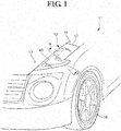
- the vehicular lamp fitting 10 of the embodiment is a lamp fitting which is provided in a vehicle 11 and is disposed on the vehicular front side and on a top face of the vehicular lateral part.
- the constituent elements of the left and right vehicular lamp fittings 10 are transversely symmetrical to each other; and therefore, only a vehicular lamp fitting 10 at the left side will be described.
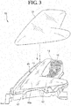
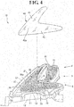
- Fig. 2 is a sectional view taken along the line A-A of Fig. 1 , and as shown in Fig. 2 , the vehicular lamp fitting 10 is equipped with: a lamp body 12; an inner panel 20 which is supported by the lamp body 12; and a reflector 30 which is engaged with the inner panel 20; and an inner lens 40 which is provided at a surface side of the reflector 30. Also, as shown in Fig. 4 , the reflector 30 has a first reflector portion 31 and a second reflector portion 32, and as shown in Fig.
- the vehicular lamp fitting 10 is equipped with an outer lens 13 to cover a surface side of the inner lens 40.
- the first light guide member 51, the second light guide member 52, the reflector 30, the inner lens 40, and light sources 61, 62 are main elements which constitute a signal lamp or an illuminating lamp in the vehicular lamp unit 10.
- a signal lamp or an illuminating lamp such as a clearance lamp (a vehicular width lamp) or a daytime running light (a daytime lamp) is included.
- the inner lens 40 is formed in a shape which bends in a substantial L-shape, and has: a first lens portion 41 of which width is gradually smaller from the bent corner part 40a to the vehicular rear side; and a second lens portion 42 of which width is gradually smaller from the corner part 40a to the vehicular oblique rear side (the left oblique rear side).
- the first lens portion 41 and the second lens portion 42 are entirely facially irradiated with light by the light sources 61, 62 (refer to Fig. 10 ), which will be described later, the first light guide member 51, the second light guide member 52, and the reflector 30.
- the thus facially light-emitted inner lens 40 can be visually recognized from the outside through an outer lens 13. It is to be noted that, at a portion which is sandwiched between the first lens portion 41 and the second lens portion 42 (at a position in a diagonal direction of the corner part 40a), a light source 15 and a reflector 16 which constitute a variety of illuminating lamps such as a headlamp or a variety of signal lamps may be disposed.
- the inner panel 20 has an opening portion 20a which is formed in a substantial L-shape in accordance with an external shape of the inner lens 40.
- Peripheral edge parts of the opening portion 20a are composed of grooves or the like in which the inner lens 40 is to be engaged, for example.
- an edge part 21 at the vehicular central side is positioned on the first light guide member 51, and an edge part 22 at the vehicular outside is positioned on the second light guide member 52.
- the reflector 30 reflects the light from the first light guide member 51 and the second light guide member 52 to the vehicular front side in a predetermined light distribution pattern.
- the reflector 30 has: a first reflector portion 31 to reflect the light that has been emitted from the first light guide member 51, to the vehicular front side; and a second reflector portion 32 to reflect the light that has been emitted from the second light guide member 52, to the vehicular front side. More specifically, the first reflector portion 31 is provided at the vehicular central side more significantly than the second reflector portion 32, and the second reflector portion 32 is provided so as to come into contact with the first reflector portion 31 at a boundary part 33 at the vehicular central side.
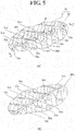
- Fig. 5 (a) shows the portion B of Fig. 4 in an enlarged manner. Namely, in the figure, a part of the portion at which the first reflector portion 31 and the second reflector portion 32 come into contact with each other is shown in an enlarged manner.
- the first reflector portion 21 and the second reflector portion 32 are formed to be integral with each other.
- the portion at which the first reflector portion 31 and the second reflector portion 32 come into contact with each other is characterized in that mountain parts 31a, 32a are respectively formed so as to come into contact with each other, and valley parts 31b, 32b are respectively formed so as to come into contact with each other, and the mountain parts 31a, 32a and the valley parts 31b, 32b each are formed in a stepwise manner which is gradually higher at level towards the vehicular rear side.
- the first reflector portion 31 and the second reflector portion 32 are formed so that the portion (the boundary part) 33 at which the first reflector portion 31 and the second reflector portion 32 come into contact with each other becomes high at level.
- the portion (the boundary part) 33 at which the first reflector portion 31 and the second reflector portion 32 come into contact with each other will be described.
- the boundary part 33 as shown in Fig. 5 (b) , it is also possible to simply form a shape such that the first reflector portion 31A and the second reflector portion 32A come into contact with each other at a wall-like alignment portion 33A.
- the wall-like alignment portion 33A it is difficult to form the wall-like alignment portion 33A so as to be a reflection surface to reflect light to the vehicular front side in the same extent as that of another reflector portion, and when the lamp fitting is seen from the vehicular front side, it has been found that a linear dark part is prone to be produced along the wall-like alignment portion 33A.
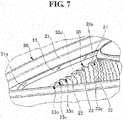
- the Inventor changed his conceptual idea and then formed such a shape as to cut out the wall-like alignment portion 33A so that such a linear dark part is not produced, namely, formed a shape having a plurality of cutout parts 33c along the boundary part 33 as is the case with the boundary part 33 shown in Fig. 5 (a) .
- the dotted line 33d of Fig. 5 (a) and Fig. 7 indicates a position which abuts against a top edge of the wall-like alignment portion 33A shown in Fig. 5 (b) , and as shown in Fig.
- the cutout parts 33c each are formed in such a shape as to cut out the wall-like alignment portion 33A from the top edge.
- the cutout parts 33a have been thus formed in the wall-like alignment portion 33A which is the linear dark part described with reference to Fig. 5 (b) , so as to thereby eliminate the wall-like alignment portion 33A which is a cause of the linear dark part.
- the linear dark part does not appear, and the portion (the boundary part) 33 at which the first reflector portion 31 and the second reflector portion 32 come into contact with each other could also be seen in the same manner as that of another reflector portion.
- first light guide member 51 and the second light guide member 52 will be described with reference to Fig. 1 , Fig. 4 , Fig. 6 to Fig. 11 , and Fig. 13 .
- the first light guide member 51 is disposed upward of an outer circumference 35 at the vehicular central side of the reflector 30, and for example, extends in both of the forward and backward directions along a bonnet 17 (refer to Fig. 1 ) of the vehicular front part or a fender panel 18 (refer to Fig. 1 ).
- the first light guide member 51 is kept at a position which is hidden by an edge part 21 of an inner panel 20 at the vehicular central side when the outer lens 13 (not shown) and the inner lens 40 are seen from the vehicular front side.
- this does not mean that the first light guide member 51 cannot be completely visually recognized from the vehicular front side by the edge part 21, but the edge part 21 covers almost all of the entirety so as to make it difficult to visually recognize the light guide member from the vehicular front side as much as possible.
- a part of the first light guide member 51 is kept at a position which can be visually recognized from the vehicular front side.
- the first light guide member 51 mainly emits the light to the first reflector portion 31 side and thus does not actively radiate the light to the vehicular front side; and therefore, even if the first light guide member 51 is seen from the vehicular front side, the member does not shine so much; and accordingly, a part which is not covered with the edge part 21 of the first light guide member 51 may be able to be visually recognized from the vehicular front side, whereas, most of the covered part is kept in a state of the order of being hardly recognized when the light guide member is seen from the vehicular front side.
- the vehicular lamp fitting 10 of the embodiment is shown with respect to the case of being disposed to be entirely oriented to the vehicular upper side; and therefore, the first light guide member 51 is disposed upward with respect to the reflector 30; and however, depending on the specification required, there is a case of such a layout oriented in an oblique lateral direction; and in this case, the first light guide member 51 is disposed in the oblique lateral direction with respect to the reflector 30. Therefore, in so far as the layout of the first light guide member 51 with respect to the reflector 30 is concerned, in general, the first light guide member is disposed at a position which opposes to the reflector 30.
- the second light guide member 52 is disposed upward of the outer circumference 36 at the vehicular outside of the reflector 30, and extends in an oblique direction with respect to the vehicular forward and backward directions.
- the second light guide member 52 extends along the bonnet 17 (refer to Fig. 1 ) of the vehicular front part or the fender panel 18 (refer to Fig. 1 ).
- Fig. 4 in respect of the second light guide member 52 as well, when the outer lens 13 (not shown) and the inner lens 40 are seen from the vehicular front side, these lenses are kept at the positions which are hidden at the edge part 22 of the inner panel 20 at the vehicular outside. In this manner, the second light guide member 52 is disposed so as not to be able to be visually recognized from the vehicular front side.
- the second light guide member 52 also mainly emits the light to the second reflector portion 32 side and thus does not actively radiate the light to the vehicular front side and thus is configured to be hardly recognized from the vehicular front side; and therefore, it is not meant that the second light guide member 52 has to be disposed at a position which is hidden at the edge part 22 so as not to be completely visually recognized from the vehicular front side. It is to be noted that, as has been described with respect to the first light guide member 51, the second light guide member 52 is also disposed upward of the reflector 30 in the embodiment; and however, more generally, the second light guide member 52 is disposed so as to oppose to the reflector 30.
- the first light guide member 51 is disposed so that the light from the first light guide member 51 can be visually recognized from the vehicular lateral side (for example, a person who is standing at a front tire 19 side (refer to Fig. 1 )) via the outer lens 13 (refer to Fig. 3 ) and the inner lens 40 (refer to Fig. 3 ).
- the vehicular lateral side for example, a person who is standing at a front tire 19 side (refer to Fig. 1 )
- the outer lens 13 for example, a person who is standing at a front tire 19 side (refer to Fig. 1 )
- the inner lens 40 respectively
- the front halved part can be visually recognized (refer to Fig.
- the first light guide member 51 has a first front end part 51a at the vehicular front side and a first rear end part 51b at the vehicular rear side.
- the first front end part 51a and the first rear end part 51b bend to a back face side of the reflector 30, and in the reflector 30, a first front side hole 37a and a first rear side hole 37b for routing the bent first front end part 51a and the first rear end part 51b, respectively, to the back face side of the reflector 30, are provided.
- the first front end part 51a and the first rear end part 51b are disposed at the back face side of the reflector 30 through the first front side hole 37a and the first rear side hole 37b, respectively.
- a light source (for example, a light emitting diode) 61 to make light incident into the first light guide member 51 is disposed at the back face side of the reflector 30 so as to oppose to the first front end part 51a and the first rear end part 51b, respectively.
- a reflection surface (a prism surface) 51c is provided along a longitudinal direction of the first light guide member 51, and the reflection surface 51c reflects the light that is guided inside of the first light guide member 51, to the first reflector portion 31 (refer to Fig. 4 ) side of the reflector 30.
- the light that has been radiated from the light source 61 and then has been made incident to the first light guide member 51 is deflected by the reflection surface 51c while being guided in the first light guide member 51, and the light exceeding a critical angle is sequentially emitted to the first reflector portion 21 (refer to Fig. 4 ) side of the reflector 30.
- the light that has been reflected by the reflection surface 51c and then to be emitted to the first reflector portion 31 side is irradiated with the spread of the order of ⁇ 20 degrees with reference to the reflection surface 51c, for example.
- a part of the light that has been emitted from the first light guide member 51 is radiated to the vehicular front side by the first reflector portion 31, and the partial light travels to the vehicular lateral side without being reflected (radiated) to the vehicular front side by the first reflector portion 31.
- the first light guide member 51 can be visually recognized from the vehicular front side and thus the light from the first light guide member 51 that travels to the vehicular lateral side, as indicated by the arrow R of Fig. 13 , is radiated to the vehicular lateral side; and therefore, the visibility from the vehicular lateral side can be improved.
- the cutout parts 33c are formed along the boundary part 33.
- the direct light from the first light guide member 51 which is to be blocked by the wall-like alignment portion 33, is also radiated to the vehicular lateral side through the cutout parts 33c. Therefore, the cutout parts 33c are formed, and the visibility from vehicular lateral side can be thereby further improved.
- the second light guide member 52 has a second front end part 52a at the vehicular central side and a second rear end part 52b at the vehicular outside.
- the second front end part 52a bends to the back face side of the reflector 30, and in the reflector 30, a second front side hole 38a for routing the bent second front end part 52a to the back face side of the reflector 30 is provided.
- the second front end part 52a is disposed at the back face side of the reflector 30 through the second front side hole 38a.
- a light source (for example, a light emitting diode) 62 to make light into the second light guide member 52 is disposed at the back face side of the reflector 30 so as to oppose to the second front end part 52a.
- a reflection surface (a prism surface) 52c is provided along the longitudinal direction of the second light guide member 52, and the reflection surface 52c reflects the light that is guided in the second light guide member 52, to the second reflector portion 32 (refer to Fig. 4 ) side of the reflector 30.
- the light that has been radiated from the light source 62 and then has been made incident to the second light guide member 52 is deflected by the reflection surface 52c while being guided in the second light guide member 52; the light exceeding the critical angle is sequentially emitted to the second reflector portion 32 (refer to Fig. 4 ) side of the reflector 30; and the light that has been emitted to the second reflector portion 32 (refer to Fig. 4 ) side is radiated to the vehicular front side by the second reflector portion 32.
- the light source 61 may be provided at least at one of the first front end part 51a and the first rear end part 51b without being limitative thereto.
- the foregoing embodiment was described with respect to the case in which the light source 62 is provided at the second front end part of the second light guide member 52, without being limitative thereto, it may be that the light source 62 is provided at the second rear end part 52b of the second light guide member 52 or that the light source 62 is provided at each end part of the second front end part and the second rear end part.
- a light source is provided at a position which can be easily visually recognized when the light source is seen from the vehicular front side, there may be a case in which a structure to hide the light source is required. In such a case, the vicinity of the hidden light source becomes dark, and the appearance is impaired. Thus, it is preferable that a light source is not provided at the position which can be easily visually recognized when the light source is seen from the vehicular front side (in the embodiment, at the second rear end part 52b).
- the first light guide member 51 and the second light guide member 52 are disposed in a state in which most portions are hidden so as to be hardly visually recognized from the vehicular front side by the edge parts 21, 22 of the inner panel 20 and thus the appearance when these members are seen from the vehicular front side is improved.
- the light that is emitted from the first light guide member 51 and the second light guide member 52 are intended to be emitted to the reflector 30 (the first reflector portion 31 and the second reflector portion 32) side, and the direct light from the first light guide member 51 and the second light guide member 52 is adapted so as not to be oriented to the vehicular front side so much; and therefore, even if a part of the first light guide member 51 and the second light guide member 52 is seen from the edge parts 21, 22 of the inner panel 20, the first light guide member 51 and the second light guide member 52 are intended to be hardly visually recognized from the vehicular front side.
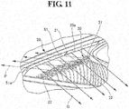
- the entirety of the inner lens 40 when the inner lens is seen from the vehicular front side, is visually recognized so that the lens has been uniformly facially illuminated (refer to Fig. 12 ) with the light that has been reflected by the reflector 30 (the first reflector portion 31 and the second reflector portion 32) and then has been radiated to the vehicular front side (the arrow P of Fig. 11 ).
- the light from the first light guide member 51 is shown, and the light from the second light guide member 52 is not shown. Therefore, there is no case in which a dark or bright matter is produced in the inner lens 40 and the appearance is impaired, and it is possible to obtain a signal lamp or an illuminating lamp without a difference in brightness when the lamp is seen from the vehicular front side.
- a linear dark part is prone to be produced along a portion (a wall-like alignment portion) 33A at which the first reflector portion 31A and the second reflector portion 32A come into contact with each other. Therefore, as shown in Fig. 5 (a) , the cutout parts 33C has been provided along the portion (the boundary part) 33 at which the first reflector portion 31 and the second reflector portion 32 come into contact with each other, so as to thereby prevent production of the linear dark part.
- the linear dark part In a case where the linear dark part is produced, if a width W (refer to Fig. 12 ) of the corner part 40a of the inner lens 40 increases, the linear dark part also becomes elongated, and is easily visually recognized; and however, as described above, the cutout parts 33c have been formed along the portion (the boundary part) 33 at which the first reflector portion 31 and the second reflector portion 32 come into contact with each other, whereby even in the case where the width W (refer to Fig. 12 ) of the corner part 40a of the inner lens 40 is large, such a linear dark part as is visually recognized does not appear on the inner lens 40; and therefore, it is possible to obtain more appropriate facial light emission.
- the portion (the boundary part) 33 at which the first reflector portion 31 and the second reflector portion 32 come into contact with each other approaches the vehicular side from the vehicular rear side (the right side of Fig. 7 ) towards the vehicular front side (the left side of Fig. 7 ), whereby a rate of direct light from the first light guide member 51, which is radiated to the vehicular lateral side without being shaded by the reflector 30, increases, and it is possible to obtain good visibility from the vehicular lateral side.
- the reflector 30 has the cutout parts 33c of which shape is formed by cutting the portion (the boundary part) 33 at which the first reflector portion 31 and the second reflector portion 32 come into contact with each other; and therefore, through the cutout parts 33c, the direct light from the first light guide member 51 is further radiated to the vehicular lateral side, so that a higher visibility from the vehicular lateral side can be obtained.
- a vehicular lamp fitting 10 is effective, in particular, for a signal lamp or an illuminating lamp such as a clearance lamp of which visibility from the vehicular lateral side is desired.
- the first front end part 51a and the first rear end part 51b of the first light guide member 51 have been disposed at the rear face side of the reflector 30, and the light source 61 has been provided at each of the first front end part 51a and the first rear end part 51b.
- the second front side hole 38a that has been provided in the reflector 30 the second front end part 52a of the second light guide member 52 has been disposed at the back face side of the reflector 30, and the light source 62 has been provided at the second front end part 52a.
- the first light guide member 51, the second light guide member 52, and the light sources 61, 62 are thus configured, and the respective light sources 61, 62 have been thereby disposed at the back face side of the reflector 30; and therefore, the light sources and the board or the like on which the light sources are to be provided are hardly visually recognized when the vehicular lamp fitting 10 is seen, and the vehicular lamp fitting 10 with its good appearance is obtained.
- first reflector portion and the second reflector portion are not such reflection surfaces respectively having the mountain parts and the valley parts, if there is a linear portion (a boundary part) at which the first reflector portion and the second reflector portion come into contact with each other, it is considered that this portion is prone to be different in reflection state from another portion.
- the boundary part if a shape obtained by cutting the linear portion (the boundary part) is formed, the light that is reflected from the reflection surfaces of the first reflector portion and the second reflector portion, and that are adjacent to the linear portion (the boundary part), is radiated to a portion of the inner lens that opposes to the boundary part, through the cutout parts, without being blocked at the linear portion (the boundary part); and therefore, it is estimated that a linear dark part is unlikely to be produced.
- the foregoing embodiment was shown with respect to the case in which the appearance when the light source is seen from the vehicular front side is improved with a simple configuration that the first light guide member 51 and the second light guide member 52 are hardly visually recognized from the vehicular front side by the edge parts 21, 22 of the inner panel 20, in terms of improvement of the appearance, the first light guide member 51 and the second light guide member 52 do not need to be hardly visually recognized from the vehicular front side by utilizing the edge parts 21, 22 of the inner panel 20, and the first light guide member 51 and the second light guide member 52 may be hardly visually recognized from the vehicular front side with another configuration.
- the reflector 30 is configured to be made of the first reflector portion 31 and the second reflector portion 32
- the reflector 30 is not limitative to the one that is made of two reflector portions, and the reflector 30 may be configured to be made of only the first reflector portion 31 as required.
- a vehicular lamp fitting 10 is the vehicular lamp fitting 10 that is disposed at the vehicular front side, and is equipped with a reflector 30 to reflect light to the vehicular front side; and the reflector 30 has a first reflector portion 31 which is provided at the vehicular central side and further the first reflector portion 31 is disposed so as to be oriented to the vehicular upper side and is provided so as to be oriented to the lower side towards the vehicular front side.
- the second embodiment of the present invention it is possible to provide a vehicular lamp fitting which emits light uniformly when it is seen from the vehicular front side, of which appearance is good, and moreover, of which visibility from the vehicle lateral side is more remarkably improved.
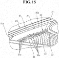
- the vehicular lamp fitting in the second embodiment in a case where the vehicular lamp fitting 10 has been disposed in a vehicle as shown in Fig. 1 , as shown in Fig. 14 , the first reflector portion 21 is disposed so as to be oriented to the vehicular upper side, and is provided so as to gently oriented to the lower side from the vehicular rear side towards the vehicular front side without being completely horizontally disposed.
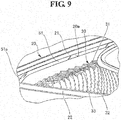
- the first reflector portion 31 and the second reflector portion 32 respectively have a plurality of reflection surfaces 31c, 32c for reflecting light to the vehicular front side, and as shown in Fig.
- these reflection surfaces 31c, 32c each are provided in a stepwise manner from the vehicular front side to the vehicular rear side.
- reflection surface portions on which the plurality of reflection surfaces 31c, 32c each have been arranged in a columnar shape are provided in a stepwise manner from the vehicular front side to the vehicular rear side.
- the plurality of reflection surfaces 31c, 32c are thus formed, whereby the reflection direction of the light of each of the reflection surfaces 31c, 32c can be individually controlled, and when the lamp fitting is seen from the vehicular front side, light distribution control is easily exercised such that the inner lens 40 facially emits light uniformly as a whole.
- Fig. 5 (a) shows the portion B of Fig. 14 in an enlarged manner. Namely, in the figure, a part of the portion at which the first reflector portion 31 and the second reflector portion 32 come into contact with each other is shown in an enlarged manner. It is to be noted that, in the second embodiment, the first reflector portion 31 and the second reflector portion 32 are formed to be integral with each other.
- first reflector portion 31 and the second reflector portion 32 are formed to be integral with each other, and there may be a configuration such that the first reflector portion 31 and the second reflector portion 32 are formed to be separate from each other, and are aligned so as to integrally connect to each other at the contact portion.
- the first reflector portion 31 and the second reflector portion 32 have been intended to form the plurality of reflection surfaces 31c, 32c that reflect light to the vehicular front side, so that the reflection direction of the light of each of the reflection surfaces 31, 32c can be individually controlled, and when the lamp fitting is seen from the vehicular front side, light distribution control is easily exercised such that the inner lens 40 facially emits light uniformly as a whole.
- the second embodiment of the present invention it is possible to provide a vehicular lamp fitting which emits light uniformly when it is seen from the vehicular front side, of which appearance is good, and moreover, of which visibility from the vehicular lateral side is more remarkably improved.
- the vehicular lamp fitting 10 in the third embodiment of the present invention is equipped with: a light guide member 51; a reflector 31 which is provided along the light guide member 51, and reflects light from the light guide member 51; and a light source which is provided at a vehicular central side of the reflector 31, and makes light incident to an end part of the light guide member 51, and the reflector 31 has a first reflection portion 34 to reflects the light into a vehicle which is provided at the light source side.
- a vehicular lamp fitting employing a light guide member which is capable of carrying out good radiation of light into a vehicle.
- the light guide member In comparison with a conventional light source of bulb type, the light guide member is small in light emission angle and thus the spread of the emitted light is small, and if the light guide member is disposed in accordance with a slant shape of the vehicular lamp fitting, there is a problem that radiation of light to the vehicular inside is hardly carried out.
- the third embodiment of the present invention has been made in view of such a circumstance, and it is an object of the third embodiment to provide a vehicular lamp fitting employing a light guide member which is capable of carrying out good radiation of light to the vehicular inside.
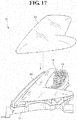
- Fig. 17 is a view showing only portions of the vehicular lamp fitting 10 and shows a state in which an outer lens 13 has been removed.
- the vehicular lamp fitting 10 is characterized in that the outer lens 13 is mounted so as to cover a front face of a housing 12, a lamp room is formed of the housing 12 and the outer lens 13, and in the lamp room, constituent elements (such as a reflector 16, a light source 15, and an inner lens 40) are provided.
- the light source 15 is a signal lamp (for example, a turn lamp) or the like, this is not always required for the vehicular lamp fitting 10, and in a case where a signal lamp or the like as a vehicular lamp fitting is provided in a vehicle 11, the constituent elements of the reflector 16 and the light source 15 may be omitted.
- Fig. 18 is a view showing a state in which the inner lens 40 of the vehicular lamp fitting 10 has been removed. It is to be noted that the outer lens 13 is not shown. As shown in Fig. 18 , the reflector 30 is mounted to the inner panel 20 that is disposed in the housing 12, and the inner lens 40 is mounted to the inner panel 20 so as to cover a front face of the inner panel 20.
- the reflector 30 is made of two faces which are a reflector 31 and a reflector 32 which have been formed to be integral with each other; a light guide member 51 is disposed so as to oppose to the reflector 31, and a light guide member 52 is disposed so as to oppose to the reflector 32.
- the light from the light guide member 51 is reflected by the reflector 31; the light from the light guide member 52 is reflected by the reflector 32; due to these reflected light beams, the inner lens 40 emits light uniformly; and for example, a clearance lamp (a vehicle width lamp) or a daytime light (daytime lamp) is configured.
- the reflector 30 is obtained as a reflector 30 formed in a substantial V-shape made of two faces which are the reflector 31 and the reflector 32 that have been formed to be integral with each other, and the inner lens 40 is also formed in a substantial V-shape, the reflector 30 and the inner lens 40 are not limitative to such shape and configuration.
- the reflector 31 there may be a configuration made of the reflector 31 and the light guide member 51 while the reflector 32 and the light guide member 52 are omitted in accordance with the required shape of the vehicular lamp fitting 10, and the reflector 31 is also limitative to a substantially triangular face as shown in Fig. 18 .
- the reflector 31 there may be a configuration in which only a reflector 31 with its substantially uniform width is provided along the light guide member 51 without the reflector 32 and the light guide member 52, and in this case, it may also be that the inner lens 40 has a substantially uniform width and is formed in such a shape as to cover the reflector 31.
- the vehicular lamp fitting 10 of the third embodiment will be described in detail.
- the reflector 32 and the light guide member 52 are not mandatory; and therefore, portions of the reflector 31 and the light guide member 51 will be mainly described hereinafter.
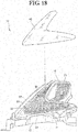
- Fig. 19 is a perspective view showing the portion A of Fig. 16 of the vehicular lamp fitting 10 in an enlarged manner, and the outer lens 13 and the inner lens 40 are not shown.
- an opening 33 is formed, and an end part of the light guide member 51, through the opening 33, is led out to the back face side of the reflector 31.
- a light source to make light incident to the end part of the light guide member 51 that has been led out is disposed. More specifically, a self-emission semiconductor-type light source such as an LED or an EL (an organic EL) on which a light emitting chip has been implemented on a board thereof is provided at the back face side of the reflector 31, and a light emission surface of the light emitting chip is disposed so as to oppose to the end part of the light guide member 51.
- a self-emission semiconductor-type light source such as an LED or an EL (an organic EL) on which a light emitting chip has been implemented on a board thereof is provided at the back face side of the reflector 31, and a light emission surface of the light emitting chip is disposed so as to oppose to the end part of the light guide member 51.
- the reflector 31 is characterized in that a first reflection portion 34 is provided in contact with the opening 33 that has been provided at the vehicular central side, and further, has a second reflection portion 35 connecting to the first reflection portion 34, that has been provided at a side spaced from the self-emission semiconductor-type light source of the first reflection portion 34.
- the first reflection portion 34 is provided at the self-emission semiconductor-type light source side of the reflector 31 more significantly than the second reflection portion 35.
- a prism structure (not shown) to emit the light that is guided in the light guide member 51, to the reflector 31 side is formed in a longitudinal direction, and the light that has been reflected so as to exceed a critical angle with this prism structure is sequentially emitted to the reflector 31 side and then the emitted light is reflected by the first reflection portion 34 and the second reflection portion 35 of the reflector 31.
- the first reflection portion 34 is formed by providing a three-stepped reflection surface 34a along the light guide member 51 from a position which comes into contact with the opening 33.
- the first reflection portion 34 is formed so as to come into contact with the opening 33 as in the embodiment.
- the reflection surface 34a coming into contact with the opening 33 is formed of one reflection surface
- a further reflection surface 34a is formed so as to have two reflection surfaces in the vertical direction
- a furthermore reflection surface 34a is formed so as o have three reflection surfaces in the vertical direction.
- each reflection surface 34a is composed of, in a vertical direction, so that a predetermined light distribution state is obtained in view of a width or the like of a width in the vertical direction of the first reflection portion 34.
- a three-stepped reflection surface 34 is provided along the light guide member 51 from the position which comes into contact with the opening 33, it may be appropriately determined how many stepped reflection surface 34a is formed in view of the fact that a predetermined light distribution state is obtained.
- each of the reflection surfaces 34a of the first reflection portion 34 is formed so as to reflect the light from the light guide member 51 to the vehicular inside.
- each of the reflection surfaces 34a is formed so as to reflect the light from the light guide member 51 to the lower side of the vehicular inside.
- the first reflection portion 34 is a reflection portion which is formed to reflect the light from the light guide member 51 to the lower side of the vehicular inside.
- each of the reflection surfaces 35a of the second reflection portion 35 is formed so as to reflect the light from the light guide member 51 to the vehicular front side.
- the second reflection portion 35 is a reflection portion which is formed so as to reflect the light from the light guide member 51 to the vehicular front side.
- a self-emission semiconductor-type light source is disposed at a back face side of a reflector 31 at a vehicular central side.
- a self-emission semiconductor-type light source which makes light incident to an end part of a light guide member 51 at an opposite side to that of the third embodiment, namely, an end part of each outside of the light guide member 51 (at an vehicular rear side).
- the end part side of the vehicular outside (the vehicular rear side) is easily visually recognized when the light source is seen from a vehicular front side, and if the self-emission semiconductor-type light source is disposed at such a position, constituent elements of the self-emission semiconductor-type light source can be visually recognized, and the appearance is impaired.
- an opening is provided in the reflector 31 as in the third embodiment so as to dispose the end part of the vehicular outside (the vehicular rear side) of the light guide member 51 at the back face side of the reflector 31 and then dispose the self-emission semiconductor-type light source at the back face side of the reflector 31, whereby the constituent elements of the self-emission semiconductor-type light source per se is hardly visually recognized from the vehicular front side, the opening that has been formed in the reflector 31 is positioned at a position which can be easily visually recognized from the vehicular front side.
- a cover for making the opening or the like hardly visible, a portion which has been covered with the cover becomes dark, and the appearance is impaired.
- the self-emission semiconductor-type light source is disposed at the vehicular central side, even if the light source is configured to be disposed at the rear face side of the reflector 31, it is possible to dispose the light source so as to be hidden at a corner of the inner panel 20 and thus the appearance can be improved.
- the opening 33 for drawing the end part of the light guide member 51 to the back face side of the reflector 31 is provided; and however, the opening 33 can be positioned at a position which is hardly visually recognized from the vehicular front side; and therefore, the appearance can be improved.
- the vehicular lamp fitting 10 slants from the vehicular front side to the vehicular rear side, it is possible to orient the direction of the opening 33 to the vehicular rear side and thus it is also possible to form the opening 33 per se so as to be hardly visually recognized from the vehicular front side; and therefore, the appearance can be more remarkably improved.
- the light to be guided in the light guide member 51 that is disposed in accordance with slanting of the vehicular lamp fitting 10 is guided from the vehicular front side to the vehicular rear side.
- the light that is guided in the light guide member 51 is emitted to the reflector 31 side by means of a prism structure
- partial light is also emitted in a direction which is different from the reflector 31 side.
- the partial light that is emitted in the direction that is different from the reflector 31 side is emitted to a light guiding direction and thus is not obtained as the light that is emitted to the vehicular inside (a lower side of the vehicular inside).
- the reflector 31 is composed of only the second reflection portion 35 that reflects light to the vehicular front side, the light that is appropriately radiated to the vehicular inside (the lower side of the vehicular inside) is not obtained; and however, as in the embodiment, the first reflection portion 34 to reflect light to the vehicular inside (the lower side of the vehicular inside) is provided at the reflector 31, thereby making it possible to obtain the light that is appropriately radiated to the vehicular inside (the lower side of the vehicular inside).
- the first reflection portion 34 reflects the light from the light guide member 51 so as to radiate the light to the vehicular inside (the lower side of the vehicular inside), and the second reflection portion 35 reflects the light so as to radiate the light to the vehicular front side.
- the first reflection portion 34 if an attempt is made to form the first reflection portion 34 at a part inside of the second reflection portion 35, a portion of the inner lens 40 irradiated with the light that has been reflected by the first reflection portion 34 is produced in the portion of the inner lens 40 irradiated with the light that has been reflected by the second reflection portion 35 when the light source is seen from the vehicular front side.
- the first reflection portion 34 and the second reflection portion 35 are characterized in that a light emission state of the inner lens 40 irradiated with the light that has been reflected by the first reflection portion 34 is different from a light emission state of the inner lens 40 irradiated with the light that has been reflected by the second reflection portion 35. More specifically, the second reflection portion 35 reflects the light to the vehicular front side, whereas the first reflection portion 34 does not reflect the light to the vehicular front side; and therefore, there may be a case in which a portion of the inner lens 40 irradiated with the light that has been reflected by the first reflection portion 34 becomes slightly dark, and the appearance is impaired when the light source is seen from the vehicular front side.
- the first reflection portion 34 is formed in contact with the opening 33.
- a portion coming into contact with the opening 33 is a position on a surface side of the reflector 31 which is the closest to the self-emission semiconductor-type light source; the light that is guided in the light guide member 51 corresponding to this portion is hardly attenuated and thus the quantity of the light is large; and the light guide member 51 per se is blight and thus the visual darkness of the inner lens 40 under the influence of the first reflection portion 34 as described above is mitigated and then impairment of the appearance is alleviated.
- the first reflection portion 34 be formed so as to come into contact with the opening 33, as long as the reflection portion is formed in the opening 33, namely, in a location which is close to the self-emission semiconductor-type light source, a similar advantageous effect is attained even if the reflection portion does not come into contact with the opening 33. Therefore, it is preferable that the first reflection portion 34 be formed at the self-emission semiconductor-type light source side of the reflector 31.
- the first reflection portion 34 is positioned in a location which is close to an end at the vehicular central side of the reflector 31, namely, is provided at a position which corresponds to an end side at the vehicular central side of the inner lens 40.
- the portion of which light emission state is different therefrom becomes conspicuous; and however, the difference in light emission state is not so conspicuous at the end side, thus making it possible to avoid impairment of the appearance.
- the first reflection portion 34 of the embodiment is provided at the position that corresponds to the end side of the inner lens 40 of which difference in light emission state is inconspicuous, thus making it possible to avoid the impairment of the appearance.
- the vehicular lamp fitting 10 slants from the vehicular front side to the vehicular rear side, if the first reflection portion 34 is formed at a portion of the reflector 31 at the vehicular rear side, there may be a case in which the light that is reflected by the first reflection 34 and then travels to the vehicular inside (the lower side of the vehicular inside) is blocked by the inner panel or the like at the vehicular inside.
- the first reflection portion 34 is formed at the vehicular central side of the reflector 31 that is to be positioned at the vehicular front side, thus making it possible to avoid the light being blocked by the inner panel or the like of the vehicular inside, the light being reflected by the first reflection portion 34 and then travels to the vehicular inside (the lower side of the vehicular inside).
- the embodiment was described with respect to the case in which the prism structure to be provided at the light guide member 51 is the prism structure to reflect the light that is guided in the light guide member 51, to the reflector 31 side.
- the prism structure to be provided at the light guide member 51 is the prism structure to reflect the light that is guided in the light guide member 51, to the reflector 31 side.
- a prism structure is provided at the back face side of the light guide member (the vehicular side) so that the light that is guided in the light guide member is emitted to the vehicular front side.
- the light that is emitted from the light guide member is not larger in angle of emission than that of another light source such as a halogen lamp, if the light guide member is disposed to slant from the vehicular front side to the vehicular rear side in accordance with slanting of the vehicular lamp fitting, even if the prism structure is formed so as to radiate light to the vehicular front side, it is difficult to appropriately radiate the light from the light guide member to the vehicular inside (the lower side of the vehicular inside).
- the reflection portion (the first reflection portion) to reflect the light from the light guide member to the vehicular inside (the lower side of the vehicular inside) is provided at a part of the reflector that is disposed at the back face side of the light guide member, thereby making it possible to provide a vehicular lamp fitting which is capable of appropriately radiating light to the vehicular inside (the lower side of the vehicular inside).
- the self-emission semiconductor-type light source is disposed at the vehicular central side in terms of the appearance that has been described hereinabove, and it is also preferable that the reflection portion (the first reflection portion) to reflect the light from the light guide member that is provided at a part of the reflector be also provided at the vehicular central side of the reflector so as to be provided at a position which is close to the self-emission semiconductor-type light source.
- the quantity of the light that is guided in the light guide member attenuates far away from the self-emission semiconductor-type light source, the light does not attenuate so much at a portion which is close to the self-emission semiconductor-type light source of the light guide member; and therefore, the quantity of the light that is emitted to the reflector side is also large in comparison with that at any other portion.
- the first reflection portion is provided in a location which is close to the self-emission semiconductor-type light source, whereby a large amount of light can be radiated to the vehicular inside (the lower side of the vehicular inside) in comparison with the case in which the first reflection portion is provided at a position which is distant from the semiconductor-type light source, and the visibility of the vehicular inside (the lower side of the vehicular inside) can be improved.
Landscapes
- Engineering & Computer Science (AREA)
- General Engineering & Computer Science (AREA)
- Physics & Mathematics (AREA)
- Optics & Photonics (AREA)
- Microelectronics & Electronic Packaging (AREA)
- General Physics & Mathematics (AREA)
- Non-Portable Lighting Devices Or Systems Thereof (AREA)
- Lighting Device Outwards From Vehicle And Optical Signal (AREA)
- Securing Globes, Refractors, Reflectors Or The Like (AREA)
Applications Claiming Priority (2)
| Application Number | Priority Date | Filing Date | Title |
|---|---|---|---|
| JP2014096113A JP2015215946A (ja) | 2014-05-07 | 2014-05-07 | 車両用灯具 |
| PCT/JP2015/061247 WO2015170551A1 (ja) | 2014-05-07 | 2015-04-10 | 車両用灯具 |
Publications (3)
| Publication Number | Publication Date |
|---|---|
| EP3141801A1 true EP3141801A1 (de) | 2017-03-15 |
| EP3141801A4 EP3141801A4 (de) | 2018-04-25 |
| EP3141801B1 EP3141801B1 (de) | 2019-06-05 |
Family
ID=54392404
Family Applications (1)
| Application Number | Title | Priority Date | Filing Date |
|---|---|---|---|
| EP15789813.1A Active EP3141801B1 (de) | 2014-05-07 | 2015-04-10 | Fahrzeuglampenarmatur |
Country Status (5)
| Country | Link |
|---|---|
| US (1) | US10371343B2 (de) |
| EP (1) | EP3141801B1 (de) |
| JP (1) | JP2015215946A (de) |
| CN (1) | CN106461180B (de) |
| WO (1) | WO2015170551A1 (de) |
Cited By (1)
| Publication number | Priority date | Publication date | Assignee | Title |
|---|---|---|---|---|
| WO2022100964A1 (de) * | 2020-11-12 | 2022-05-19 | Zkw Group Gmbh | Beleuchtungsvorrichtung für einen kraftfahrzeugscheinwerfer |
Families Citing this family (7)
| Publication number | Priority date | Publication date | Assignee | Title |
|---|---|---|---|---|
| JP7034750B2 (ja) * | 2018-02-09 | 2022-03-14 | スタンレー電気株式会社 | 車両用灯具 |
| JP7020259B2 (ja) * | 2018-04-09 | 2022-02-16 | トヨタ自動車株式会社 | 車両用灯具 |
| JP6695925B2 (ja) * | 2018-04-16 | 2020-05-20 | 本田技研工業株式会社 | 鞍乗り型車両用灯火器 |
| JP2019212515A (ja) * | 2018-06-06 | 2019-12-12 | 株式会社小糸製作所 | 車両用灯具 |
| JP7242313B2 (ja) * | 2019-01-24 | 2023-03-20 | スタンレー電気株式会社 | 車両用灯具 |
| JP7399715B2 (ja) * | 2020-01-09 | 2023-12-18 | 株式会社小糸製作所 | 射出成形品 |
| US11512828B2 (en) * | 2020-12-01 | 2022-11-29 | Valeo Vision | Automotive lamp optical system with light diffusive projection lens |
Family Cites Families (15)
| Publication number | Priority date | Publication date | Assignee | Title |
|---|---|---|---|---|
| DE19624244B4 (de) * | 1996-06-18 | 2010-01-14 | Automotive Lighting Reutlingen Gmbh | Leuchte für Fahrzeuge |
| JP2003068115A (ja) * | 2001-08-30 | 2003-03-07 | Koito Mfg Co Ltd | 車両用灯具 |
| JP2003100114A (ja) * | 2001-09-19 | 2003-04-04 | Koito Mfg Co Ltd | 車両用灯具 |
| JP4027821B2 (ja) * | 2003-03-11 | 2007-12-26 | 株式会社小糸製作所 | 車両用灯具 |
| DE10311317A1 (de) * | 2003-03-14 | 2004-09-23 | Volkswagen Ag | Leuchteinrichtung für Fahrzeuge |
| DE102007005779A1 (de) * | 2007-02-06 | 2008-08-07 | Automotive Lighting Reutlingen Gmbh | Beleuchtungseinrichtung für ein Fahrzeug und Scheinwerfer mit einer solchen Beleuchtungseinrichtung |
| DE102008038668B4 (de) * | 2008-08-12 | 2025-07-10 | HELLA GmbH & Co. KGaA | Signalleuchte für Fahrzeuge, die eine Mehrzahl von parallel zueinander verlaufenden Lichtleitelementen und einen Reflektor aufweist |
| JP5575592B2 (ja) * | 2010-09-17 | 2014-08-20 | 株式会社小糸製作所 | 車両用灯具 |
| DE102011004349A1 (de) * | 2011-02-17 | 2012-08-23 | Automotive Lighting Reutlingen Gmbh | Beleuchtungseinrichtung eines Kraftfahrzeugs |
| JP5749576B2 (ja) * | 2011-06-07 | 2015-07-15 | 株式会社小糸製作所 | 車両用灯具 |
| JP2013048036A (ja) | 2011-08-29 | 2013-03-07 | Toyoda Gosei Co Ltd | 車両用灯具 |
| JP5897919B2 (ja) | 2012-02-07 | 2016-04-06 | 株式会社小糸製作所 | 車両用灯具 |
| JP6029298B2 (ja) | 2012-03-14 | 2016-11-24 | 株式会社小糸製作所 | 車両用灯具 |
| JP6134111B2 (ja) | 2012-09-13 | 2017-05-24 | 株式会社小糸製作所 | 車両用灯具 |
| TW201447178A (zh) * | 2013-06-06 | 2014-12-16 | Tyc Brother Ind Co Ltd | 導光透鏡 |
-
2014
- 2014-05-07 JP JP2014096113A patent/JP2015215946A/ja active Pending
-
2015
- 2015-04-10 WO PCT/JP2015/061247 patent/WO2015170551A1/ja not_active Ceased
- 2015-04-10 CN CN201580023247.8A patent/CN106461180B/zh active Active
- 2015-04-10 US US15/309,065 patent/US10371343B2/en active Active
- 2015-04-10 EP EP15789813.1A patent/EP3141801B1/de active Active
Cited By (2)
| Publication number | Priority date | Publication date | Assignee | Title |
|---|---|---|---|---|
| WO2022100964A1 (de) * | 2020-11-12 | 2022-05-19 | Zkw Group Gmbh | Beleuchtungsvorrichtung für einen kraftfahrzeugscheinwerfer |
| EP4001744A1 (de) * | 2020-11-12 | 2022-05-25 | ZKW Group GmbH | Beleuchtungsvorrichtung für einen kraftfahrzeugscheinwerfer |
Also Published As
| Publication number | Publication date |
|---|---|
| EP3141801B1 (de) | 2019-06-05 |
| JP2015215946A (ja) | 2015-12-03 |
| EP3141801A4 (de) | 2018-04-25 |
| CN106461180B (zh) | 2019-05-21 |
| US20170067615A1 (en) | 2017-03-09 |
| CN106461180A (zh) | 2017-02-22 |
| WO2015170551A1 (ja) | 2015-11-12 |
| US10371343B2 (en) | 2019-08-06 |
Similar Documents
| Publication | Publication Date | Title |
|---|---|---|
| EP3141801B1 (de) | Fahrzeuglampenarmatur | |
| CN108087838B (zh) | 车辆用灯具 | |
| EP2693105B1 (de) | Fahrzeugbeleuchtungseinheit | |
| US10036522B2 (en) | Vehicular lamp | |
| KR101423874B1 (ko) | 차량용 등기구 | |
| US9328885B2 (en) | Vehicle lighting unit | |
| US9701240B2 (en) | Vehicle lighting unit having light guiding lens | |
| EP2990720A1 (de) | Fahrzeugbeleuchtungsvorrichtung | |
| CN102997153A (zh) | 车辆用灯具 | |
| US20200318804A1 (en) | Headlight Module With A Low-Beam Function And A High-Beam Function Based On Light Emitting Diodes | |
| US9470390B2 (en) | Vehicular lamp | |
| US11754251B2 (en) | Vehicular lamp | |
| US7572041B2 (en) | Vehicle lamp | |
| CN109716017B (zh) | 用于车辆的具有全息元件和棱镜反射器的发光装置 | |
| JP6221767B2 (ja) | 車両用灯具 | |
| KR20160035011A (ko) | 통합된 led들을 포함하는, 특히 자동차 조명 부품용 조명 시스템 | |
| EP3838564A1 (de) | Fahrzeugbeleuchtungshalterung | |
| US10883688B2 (en) | Lamp device for vehicle | |
| US10731822B2 (en) | Light-emitting device for motor vehicle | |
| JP6402449B2 (ja) | 車両用灯具 | |
| EP3578877A1 (de) | Fahrzeuglampe | |
| JP6832125B2 (ja) | 車両用灯具 | |
| JP7748242B2 (ja) | 表示灯 | |
| CN202063070U (zh) | 雾灯的装饰件构造 | |
| JP6171266B2 (ja) | 車両用灯具 |
Legal Events
| Date | Code | Title | Description |
|---|---|---|---|
| STAA | Information on the status of an ep patent application or granted ep patent |
Free format text: STATUS: THE INTERNATIONAL PUBLICATION HAS BEEN MADE |
|
| PUAI | Public reference made under article 153(3) epc to a published international application that has entered the european phase |
Free format text: ORIGINAL CODE: 0009012 |
|
| STAA | Information on the status of an ep patent application or granted ep patent |
Free format text: STATUS: REQUEST FOR EXAMINATION WAS MADE |
|
| 17P | Request for examination filed |
Effective date: 20161107 |
|
| AK | Designated contracting states |
Kind code of ref document: A1 Designated state(s): AL AT BE BG CH CY CZ DE DK EE ES FI FR GB GR HR HU IE IS IT LI LT LU LV MC MK MT NL NO PL PT RO RS SE SI SK SM TR |
|
| AX | Request for extension of the european patent |
Extension state: BA ME |
|
| DAV | Request for validation of the european patent (deleted) | ||
| DAX | Request for extension of the european patent (deleted) | ||
| RIC1 | Information provided on ipc code assigned before grant |
Ipc: F21V 17/00 20060101ALI20171205BHEP Ipc: F21W 101/02 00000000ALN20171205BHEP Ipc: F21V 7/09 20060101ALI20171205BHEP Ipc: F21S 8/10 00000000AFI20171205BHEP Ipc: F21Y 115/10 20160101ALN20171205BHEP Ipc: F21V 8/00 20060101ALI20171205BHEP |
|
| A4 | Supplementary search report drawn up and despatched |
Effective date: 20180323 |
|
| RIC1 | Information provided on ipc code assigned before grant |
Ipc: F21Y 115/10 20160101ALN20180319BHEP Ipc: F21S 43/237 20180101ALI20180319BHEP Ipc: F21V 7/09 20060101AFI20180319BHEP Ipc: F21S 41/33 20180101ALI20180319BHEP Ipc: F21V 7/04 20060101ALI20180319BHEP Ipc: F21V 8/00 20060101ALI20180319BHEP Ipc: F21S 41/24 20180101ALI20180319BHEP Ipc: F21V 17/00 20060101ALI20180319BHEP |
|
| REG | Reference to a national code |
Ref country code: DE Ref legal event code: R079 Ref document number: 602015031484 Country of ref document: DE Free format text: PREVIOUS MAIN CLASS: F21S0008100000 Ipc: F21V0007090000 |
|
| GRAP | Despatch of communication of intention to grant a patent |
Free format text: ORIGINAL CODE: EPIDOSNIGR1 |
|
| STAA | Information on the status of an ep patent application or granted ep patent |
Free format text: STATUS: GRANT OF PATENT IS INTENDED |
|
| RIC1 | Information provided on ipc code assigned before grant |
Ipc: F21V 17/00 20060101ALI20181119BHEP Ipc: F21V 7/04 20060101ALI20181119BHEP Ipc: F21V 7/09 20060101AFI20181119BHEP Ipc: F21S 41/33 20180101ALI20181119BHEP Ipc: F21V 8/00 20060101ALI20181119BHEP Ipc: F21S 43/237 20180101ALI20181119BHEP Ipc: F21Y 115/10 20160101ALN20181119BHEP Ipc: F21S 41/24 20180101ALI20181119BHEP |
|
| RIC1 | Information provided on ipc code assigned before grant |
Ipc: F21Y 115/10 20160101ALN20181127BHEP Ipc: F21S 43/237 20180101ALI20181127BHEP Ipc: F21S 41/24 20180101ALI20181127BHEP Ipc: F21V 7/04 20060101ALI20181127BHEP Ipc: F21V 17/00 20060101ALI20181127BHEP Ipc: F21S 41/33 20180101ALI20181127BHEP Ipc: F21V 8/00 20060101ALI20181127BHEP Ipc: F21V 7/09 20060101AFI20181127BHEP |
|
| INTG | Intention to grant announced |
Effective date: 20181212 |
|
| RIC1 | Information provided on ipc code assigned before grant |
Ipc: F21S 41/33 20180101ALI20181127BHEP Ipc: F21V 17/00 20060101ALI20181127BHEP Ipc: F21S 41/24 20180101ALI20181127BHEP Ipc: F21S 43/237 20180101ALI20181127BHEP Ipc: F21Y 115/10 20160101ALN20181127BHEP Ipc: F21V 8/00 20060101ALI20181127BHEP Ipc: F21V 7/09 20060101AFI20181127BHEP Ipc: F21V 7/04 20060101ALI20181127BHEP |
|
| GRAS | Grant fee paid |
Free format text: ORIGINAL CODE: EPIDOSNIGR3 |
|
| GRAA | (expected) grant |
Free format text: ORIGINAL CODE: 0009210 |
|
| STAA | Information on the status of an ep patent application or granted ep patent |
Free format text: STATUS: THE PATENT HAS BEEN GRANTED |
|
| AK | Designated contracting states |
Kind code of ref document: B1 Designated state(s): AL AT BE BG CH CY CZ DE DK EE ES FI FR GB GR HR HU IE IS IT LI LT LU LV MC MK MT NL NO PL PT RO RS SE SI SK SM TR |
|
| REG | Reference to a national code |
Ref country code: GB Ref legal event code: FG4D |
|
| REG | Reference to a national code |
Ref country code: CH Ref legal event code: EP |
|
| REG | Reference to a national code |
Ref country code: AT Ref legal event code: REF Ref document number: 1140374 Country of ref document: AT Kind code of ref document: T Effective date: 20190615 |
|
| REG | Reference to a national code |
Ref country code: DE Ref legal event code: R096 Ref document number: 602015031484 Country of ref document: DE |
|
| REG | Reference to a national code |
Ref country code: IE Ref legal event code: FG4D |
|
| REG | Reference to a national code |
Ref country code: NL Ref legal event code: MP Effective date: 20190605 |
|
| REG | Reference to a national code |
Ref country code: LT Ref legal event code: MG4D |
|
| PG25 | Lapsed in a contracting state [announced via postgrant information from national office to epo] |
Ref country code: FI Free format text: LAPSE BECAUSE OF FAILURE TO SUBMIT A TRANSLATION OF THE DESCRIPTION OR TO PAY THE FEE WITHIN THE PRESCRIBED TIME-LIMIT Effective date: 20190605 Ref country code: LT Free format text: LAPSE BECAUSE OF FAILURE TO SUBMIT A TRANSLATION OF THE DESCRIPTION OR TO PAY THE FEE WITHIN THE PRESCRIBED TIME-LIMIT Effective date: 20190605 Ref country code: AL Free format text: LAPSE BECAUSE OF FAILURE TO SUBMIT A TRANSLATION OF THE DESCRIPTION OR TO PAY THE FEE WITHIN THE PRESCRIBED TIME-LIMIT Effective date: 20190605 Ref country code: ES Free format text: LAPSE BECAUSE OF FAILURE TO SUBMIT A TRANSLATION OF THE DESCRIPTION OR TO PAY THE FEE WITHIN THE PRESCRIBED TIME-LIMIT Effective date: 20190605 Ref country code: SE Free format text: LAPSE BECAUSE OF FAILURE TO SUBMIT A TRANSLATION OF THE DESCRIPTION OR TO PAY THE FEE WITHIN THE PRESCRIBED TIME-LIMIT Effective date: 20190605 Ref country code: HR Free format text: LAPSE BECAUSE OF FAILURE TO SUBMIT A TRANSLATION OF THE DESCRIPTION OR TO PAY THE FEE WITHIN THE PRESCRIBED TIME-LIMIT Effective date: 20190605 Ref country code: NO Free format text: LAPSE BECAUSE OF FAILURE TO SUBMIT A TRANSLATION OF THE DESCRIPTION OR TO PAY THE FEE WITHIN THE PRESCRIBED TIME-LIMIT Effective date: 20190905 |
|
| PG25 | Lapsed in a contracting state [announced via postgrant information from national office to epo] |
Ref country code: GR Free format text: LAPSE BECAUSE OF FAILURE TO SUBMIT A TRANSLATION OF THE DESCRIPTION OR TO PAY THE FEE WITHIN THE PRESCRIBED TIME-LIMIT Effective date: 20190906 Ref country code: LV Free format text: LAPSE BECAUSE OF FAILURE TO SUBMIT A TRANSLATION OF THE DESCRIPTION OR TO PAY THE FEE WITHIN THE PRESCRIBED TIME-LIMIT Effective date: 20190605 Ref country code: BG Free format text: LAPSE BECAUSE OF FAILURE TO SUBMIT A TRANSLATION OF THE DESCRIPTION OR TO PAY THE FEE WITHIN THE PRESCRIBED TIME-LIMIT Effective date: 20190905 Ref country code: RS Free format text: LAPSE BECAUSE OF FAILURE TO SUBMIT A TRANSLATION OF THE DESCRIPTION OR TO PAY THE FEE WITHIN THE PRESCRIBED TIME-LIMIT Effective date: 20190605 |
|
| REG | Reference to a national code |
Ref country code: AT Ref legal event code: MK05 Ref document number: 1140374 Country of ref document: AT Kind code of ref document: T Effective date: 20190605 |
|
| PG25 | Lapsed in a contracting state [announced via postgrant information from national office to epo] |
Ref country code: EE Free format text: LAPSE BECAUSE OF FAILURE TO SUBMIT A TRANSLATION OF THE DESCRIPTION OR TO PAY THE FEE WITHIN THE PRESCRIBED TIME-LIMIT Effective date: 20190605 Ref country code: SK Free format text: LAPSE BECAUSE OF FAILURE TO SUBMIT A TRANSLATION OF THE DESCRIPTION OR TO PAY THE FEE WITHIN THE PRESCRIBED TIME-LIMIT Effective date: 20190605 Ref country code: CZ Free format text: LAPSE BECAUSE OF FAILURE TO SUBMIT A TRANSLATION OF THE DESCRIPTION OR TO PAY THE FEE WITHIN THE PRESCRIBED TIME-LIMIT Effective date: 20190605 Ref country code: NL Free format text: LAPSE BECAUSE OF FAILURE TO SUBMIT A TRANSLATION OF THE DESCRIPTION OR TO PAY THE FEE WITHIN THE PRESCRIBED TIME-LIMIT Effective date: 20190605 Ref country code: RO Free format text: LAPSE BECAUSE OF FAILURE TO SUBMIT A TRANSLATION OF THE DESCRIPTION OR TO PAY THE FEE WITHIN THE PRESCRIBED TIME-LIMIT Effective date: 20190605 Ref country code: PT Free format text: LAPSE BECAUSE OF FAILURE TO SUBMIT A TRANSLATION OF THE DESCRIPTION OR TO PAY THE FEE WITHIN THE PRESCRIBED TIME-LIMIT Effective date: 20191007 Ref country code: AT Free format text: LAPSE BECAUSE OF FAILURE TO SUBMIT A TRANSLATION OF THE DESCRIPTION OR TO PAY THE FEE WITHIN THE PRESCRIBED TIME-LIMIT Effective date: 20190605 |
|
| PG25 | Lapsed in a contracting state [announced via postgrant information from national office to epo] |
Ref country code: SM Free format text: LAPSE BECAUSE OF FAILURE TO SUBMIT A TRANSLATION OF THE DESCRIPTION OR TO PAY THE FEE WITHIN THE PRESCRIBED TIME-LIMIT Effective date: 20190605 Ref country code: IT Free format text: LAPSE BECAUSE OF FAILURE TO SUBMIT A TRANSLATION OF THE DESCRIPTION OR TO PAY THE FEE WITHIN THE PRESCRIBED TIME-LIMIT Effective date: 20190605 Ref country code: IS Free format text: LAPSE BECAUSE OF FAILURE TO SUBMIT A TRANSLATION OF THE DESCRIPTION OR TO PAY THE FEE WITHIN THE PRESCRIBED TIME-LIMIT Effective date: 20191005 |
|
| REG | Reference to a national code |
Ref country code: DE Ref legal event code: R097 Ref document number: 602015031484 Country of ref document: DE |
|
| PG25 | Lapsed in a contracting state [announced via postgrant information from national office to epo] |
Ref country code: TR Free format text: LAPSE BECAUSE OF FAILURE TO SUBMIT A TRANSLATION OF THE DESCRIPTION OR TO PAY THE FEE WITHIN THE PRESCRIBED TIME-LIMIT Effective date: 20190605 |
|
| PLBE | No opposition filed within time limit |
Free format text: ORIGINAL CODE: 0009261 |
|
| STAA | Information on the status of an ep patent application or granted ep patent |
Free format text: STATUS: NO OPPOSITION FILED WITHIN TIME LIMIT |
|
| PG25 | Lapsed in a contracting state [announced via postgrant information from national office to epo] |
Ref country code: PL Free format text: LAPSE BECAUSE OF FAILURE TO SUBMIT A TRANSLATION OF THE DESCRIPTION OR TO PAY THE FEE WITHIN THE PRESCRIBED TIME-LIMIT Effective date: 20190605 Ref country code: DK Free format text: LAPSE BECAUSE OF FAILURE TO SUBMIT A TRANSLATION OF THE DESCRIPTION OR TO PAY THE FEE WITHIN THE PRESCRIBED TIME-LIMIT Effective date: 20190605 |
|
| 26N | No opposition filed |
Effective date: 20200306 |
|
| PG25 | Lapsed in a contracting state [announced via postgrant information from national office to epo] |
Ref country code: SI Free format text: LAPSE BECAUSE OF FAILURE TO SUBMIT A TRANSLATION OF THE DESCRIPTION OR TO PAY THE FEE WITHIN THE PRESCRIBED TIME-LIMIT Effective date: 20190605 |
|
| PG25 | Lapsed in a contracting state [announced via postgrant information from national office to epo] |
Ref country code: MC Free format text: LAPSE BECAUSE OF FAILURE TO SUBMIT A TRANSLATION OF THE DESCRIPTION OR TO PAY THE FEE WITHIN THE PRESCRIBED TIME-LIMIT Effective date: 20190605 |
|
| REG | Reference to a national code |
Ref country code: CH Ref legal event code: PL |
|
| PG25 | Lapsed in a contracting state [announced via postgrant information from national office to epo] |
Ref country code: CH Free format text: LAPSE BECAUSE OF NON-PAYMENT OF DUE FEES Effective date: 20200430 Ref country code: LI Free format text: LAPSE BECAUSE OF NON-PAYMENT OF DUE FEES Effective date: 20200430 Ref country code: LU Free format text: LAPSE BECAUSE OF NON-PAYMENT OF DUE FEES Effective date: 20200410 |
|
| REG | Reference to a national code |
Ref country code: BE Ref legal event code: MM Effective date: 20200430 |
|
| PG25 | Lapsed in a contracting state [announced via postgrant information from national office to epo] |
Ref country code: BE Free format text: LAPSE BECAUSE OF NON-PAYMENT OF DUE FEES Effective date: 20200430 |
|
| PG25 | Lapsed in a contracting state [announced via postgrant information from national office to epo] |
Ref country code: IE Free format text: LAPSE BECAUSE OF NON-PAYMENT OF DUE FEES Effective date: 20200410 |
|
| PG25 | Lapsed in a contracting state [announced via postgrant information from national office to epo] |
Ref country code: MT Free format text: LAPSE BECAUSE OF FAILURE TO SUBMIT A TRANSLATION OF THE DESCRIPTION OR TO PAY THE FEE WITHIN THE PRESCRIBED TIME-LIMIT Effective date: 20190605 Ref country code: CY Free format text: LAPSE BECAUSE OF FAILURE TO SUBMIT A TRANSLATION OF THE DESCRIPTION OR TO PAY THE FEE WITHIN THE PRESCRIBED TIME-LIMIT Effective date: 20190605 |
|
| PG25 | Lapsed in a contracting state [announced via postgrant information from national office to epo] |
Ref country code: MK Free format text: LAPSE BECAUSE OF FAILURE TO SUBMIT A TRANSLATION OF THE DESCRIPTION OR TO PAY THE FEE WITHIN THE PRESCRIBED TIME-LIMIT Effective date: 20190605 |
|
| PGFP | Annual fee paid to national office [announced via postgrant information from national office to epo] |
Ref country code: DE Payment date: 20250422 Year of fee payment: 11 |
|
| PGFP | Annual fee paid to national office [announced via postgrant information from national office to epo] |
Ref country code: GB Payment date: 20250423 Year of fee payment: 11 |
|
| PGFP | Annual fee paid to national office [announced via postgrant information from national office to epo] |
Ref country code: FR Payment date: 20250425 Year of fee payment: 11 |