EP3141817B1 - Chambre de combustion de turbine à gaz - Google Patents
Chambre de combustion de turbine à gaz Download PDFInfo
- Publication number
- EP3141817B1 EP3141817B1 EP16187715.4A EP16187715A EP3141817B1 EP 3141817 B1 EP3141817 B1 EP 3141817B1 EP 16187715 A EP16187715 A EP 16187715A EP 3141817 B1 EP3141817 B1 EP 3141817B1
- Authority
- EP
- European Patent Office
- Prior art keywords
- air
- fuel
- flow path
- air hole
- hole plate
- Prior art date
- Legal status (The legal status is an assumption and is not a legal conclusion. Google has not performed a legal analysis and makes no representation as to the accuracy of the status listed.)
- Active
Links
Images


Classifications
-
- F—MECHANICAL ENGINEERING; LIGHTING; HEATING; WEAPONS; BLASTING
- F23—COMBUSTION APPARATUS; COMBUSTION PROCESSES
- F23R—GENERATING COMBUSTION PRODUCTS OF HIGH PRESSURE OR HIGH VELOCITY, e.g. GAS-TURBINE COMBUSTION CHAMBERS
- F23R3/00—Continuous combustion chambers using liquid or gaseous fuel
- F23R3/28—Continuous combustion chambers using liquid or gaseous fuel characterised by the fuel supply
- F23R3/286—Continuous combustion chambers using liquid or gaseous fuel characterised by the fuel supply having fuel-air premixing devices
-
- F—MECHANICAL ENGINEERING; LIGHTING; HEATING; WEAPONS; BLASTING
- F23—COMBUSTION APPARATUS; COMBUSTION PROCESSES
- F23R—GENERATING COMBUSTION PRODUCTS OF HIGH PRESSURE OR HIGH VELOCITY, e.g. GAS-TURBINE COMBUSTION CHAMBERS
- F23R3/00—Continuous combustion chambers using liquid or gaseous fuel
- F23R3/02—Continuous combustion chambers using liquid or gaseous fuel characterised by the air-flow or gas-flow configuration
- F23R3/26—Controlling the air flow
-
- F—MECHANICAL ENGINEERING; LIGHTING; HEATING; WEAPONS; BLASTING
- F23—COMBUSTION APPARATUS; COMBUSTION PROCESSES
- F23R—GENERATING COMBUSTION PRODUCTS OF HIGH PRESSURE OR HIGH VELOCITY, e.g. GAS-TURBINE COMBUSTION CHAMBERS
- F23R3/00—Continuous combustion chambers using liquid or gaseous fuel
- F23R3/02—Continuous combustion chambers using liquid or gaseous fuel characterised by the air-flow or gas-flow configuration
- F23R3/04—Air inlet arrangements
- F23R3/06—Arrangement of apertures along the flame tube
-
- F—MECHANICAL ENGINEERING; LIGHTING; HEATING; WEAPONS; BLASTING
- F02—COMBUSTION ENGINES; HOT-GAS OR COMBUSTION-PRODUCT ENGINE PLANTS
- F02C—GAS-TURBINE PLANTS; AIR INTAKES FOR JET-PROPULSION PLANTS; CONTROLLING FUEL SUPPLY IN AIR-BREATHING JET-PROPULSION PLANTS
- F02C7/00—Features, components parts, details or accessories, not provided for in, or of interest apart form groups F02C1/00 - F02C6/00; Air intakes for jet-propulsion plants
- F02C7/22—Fuel supply systems
-
- F—MECHANICAL ENGINEERING; LIGHTING; HEATING; WEAPONS; BLASTING
- F23—COMBUSTION APPARATUS; COMBUSTION PROCESSES
- F23R—GENERATING COMBUSTION PRODUCTS OF HIGH PRESSURE OR HIGH VELOCITY, e.g. GAS-TURBINE COMBUSTION CHAMBERS
- F23R3/00—Continuous combustion chambers using liquid or gaseous fuel
- F23R3/02—Continuous combustion chambers using liquid or gaseous fuel characterised by the air-flow or gas-flow configuration
- F23R3/04—Air inlet arrangements
- F23R3/10—Air inlet arrangements for primary air
- F23R3/12—Air inlet arrangements for primary air inducing a vortex
- F23R3/14—Air inlet arrangements for primary air inducing a vortex by using swirl vanes
-
- F—MECHANICAL ENGINEERING; LIGHTING; HEATING; WEAPONS; BLASTING
- F23—COMBUSTION APPARATUS; COMBUSTION PROCESSES
- F23R—GENERATING COMBUSTION PRODUCTS OF HIGH PRESSURE OR HIGH VELOCITY, e.g. GAS-TURBINE COMBUSTION CHAMBERS
- F23R3/00—Continuous combustion chambers using liquid or gaseous fuel
- F23R3/02—Continuous combustion chambers using liquid or gaseous fuel characterised by the air-flow or gas-flow configuration
- F23R3/16—Continuous combustion chambers using liquid or gaseous fuel characterised by the air-flow or gas-flow configuration with devices inside the flame tube or the combustion chamber to influence the air or gas flow
-
- F—MECHANICAL ENGINEERING; LIGHTING; HEATING; WEAPONS; BLASTING
- F23—COMBUSTION APPARATUS; COMBUSTION PROCESSES
- F23R—GENERATING COMBUSTION PRODUCTS OF HIGH PRESSURE OR HIGH VELOCITY, e.g. GAS-TURBINE COMBUSTION CHAMBERS
- F23R3/00—Continuous combustion chambers using liquid or gaseous fuel
- F23R3/42—Continuous combustion chambers using liquid or gaseous fuel characterised by the arrangement or form of the flame tubes or combustion chambers
-
- F—MECHANICAL ENGINEERING; LIGHTING; HEATING; WEAPONS; BLASTING
- F05—INDEXING SCHEMES RELATING TO ENGINES OR PUMPS IN VARIOUS SUBCLASSES OF CLASSES F01-F04
- F05D—INDEXING SCHEME FOR ASPECTS RELATING TO NON-POSITIVE-DISPLACEMENT MACHINES OR ENGINES, GAS-TURBINES OR JET-PROPULSION PLANTS
- F05D2240/00—Components
- F05D2240/35—Combustors or associated equipment
-
- F—MECHANICAL ENGINEERING; LIGHTING; HEATING; WEAPONS; BLASTING
- F23—COMBUSTION APPARATUS; COMBUSTION PROCESSES
- F23R—GENERATING COMBUSTION PRODUCTS OF HIGH PRESSURE OR HIGH VELOCITY, e.g. GAS-TURBINE COMBUSTION CHAMBERS
- F23R2900/00—Special features of, or arrangements for continuous combustion chambers; Combustion processes therefor
- F23R2900/00012—Details of sealing devices
Definitions
- the present invention relates to a gas turbine combustor.
- NOx nitrogen oxide
- gas turbines that include, for example, compressors, combustors, and turbines.
- a known technique for achieving greater efficiency in the gas turbine of this type is to increase the temperature of a flame formed in the combustor to thereby increase the temperature of the combustion gas at a turbine inlet. This technique, however, entails an increased amount of NOx emissions with an increasing flame temperature.
- Premixed combustion refers to a combustion system in which fuel and air are mixed together in advance and a resultant mixture is supplied to a combustion chamber for combustion. Because fuel and air are mixed together in advance before being supplied to the combustion chamber in premixed combustion, the temperature of a flame formed in the combustion chamber is equalized and the amount of NOx emissions in the combustor is reduced accordingly.
- a combustion velocity increases. The increased combustion velocity causes what is called a backfire to be likely to occur, in which the flame formed in the combustion chamber flows back into a premixer.
- a combustor that reduces the amount of NOx emissions and backfire resistance has been developed is offered (see, for example, JP-A-2014-55697 ).
- US 2014/00 83 102 A1 discloses a combustor according to the preamble of claim 1. This combustor can form stable flame and reduce the metal temperature at a liner and an outlet end face of a burner.
- US 2012/00 45 725 A1 discloses combustor of a gas turbine having a structure for reducing deflection and turbulence of airflow flowing inside the combustor.
- an end cover of a combustor has a central region protruding toward the side of an air hole plate and a recessed region is formed on an outer peripheral side in a radial direction of the end cover.
- the present invention has been made in view of the foregoing situation and it is an object of the present invention to provide a gas turbine combustor capable of reducing a deviation in the air flow rate supplied to each air hole.
- the present invention provides a gas turbine combustor.
- the gas turbine combustor includes: an inner casing that defines thereinside a combustion chamber; an outer casing disposed so as to cover the inner casing; an annular flow path disposed between the inner casing and the outer casing, the annular flow path allowing high-pressure air to flowing therethrough; a fuel header disposed downstream of the outer casing in a flow direction of the high-pressure air; a plurality of fuel nozzles supported concentrically on the fuel header; an air hole plate disposed downstream of the fuel nozzles in a flow direction of fuel, the air hole plate having a plurality of air holes associated with the respective fuel nozzles; a guide including a wall portion that protrudes from an outer peripheral surface of the air hole plate further than an outer peripheral side of the inner casing and a bent portion formed into a convex shape protruding toward the outer casing and the fuel header and arcuately connected with an air hole of the plurality of air holes on an
- the present invention can provide a gas turbine combustor capable of reducing a deviation in the air flow rate supplied to each air hole.
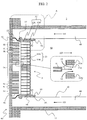
- Fig. 1 is a diagram showing an exemplary configuration of a gas turbine plant to which a gas turbine combustor (hereinafter referred to as a combustor) according to a first embodiment of the present invention is applied.
- the gas turbine plant 1000 according to the first embodiment includes a compressor 1, a combustor 2, a turbine 3, and a generator 30.
- the compressor 1 is rotatably driven by the turbine 3.
- the compressor 1 compresses air (intake air) 100 drawn in via an intake portion (not shown) to generate high-pressure air (combustion air) 101 and supplies the high-pressure air 101 to the combustor 2.
- the combustor 2 mixes the high-pressure air 101 supplied from the compressor 1 with fuel supplied from a fuel system 200 (to be described later) and burns a resultant mixture to thereby generate a combustion gas 102 at high temperature.
- the combustor 2 then supplies the combustion gas 102 to the turbine 3.
- the turbine 3 is rotatably driven through expansion of the combustion gas 102 supplied from the combustor 2.
- the generator 30 is connected coaxially with the turbine 3 and converts rotational power of the turbine 3 into electric power.
- the compressor 1, the turbine 3, and the generator 30 are connected with each other by a shaft 31.
- the combustor 2 is mounted in a casing 4 of the gas turbine.
- the combustor 2 includes a burner 5, a combustor liner (hereinafter referred to as an inner casing) 10, a flow sleeve (hereinafter referred to as an outer casing) 11, a transition piece inner casing 12, a transition piece outer casing 13, the fuel system 200, and a fuel header 40.
- the inner casing 10 is disposed downstream of the burner 5 in a flow direction of the combustion gas 102.
- “upstream” and “downstream” in a flow direction of the combustion gas 102 will be referred to as “combustion gas upstream” and “combustion gas downstream.”
- the inner casing 10 is formed into a cylinder to isolate the high-pressure air 101 supplied from the compressor 1 from the combustion gas 102 generated in the combustor 2.
- the outer casing 11 is formed into a cylinder disposed on an outer peripheral side of the inner casing 10 so as to cover thereinside the inner casing 10.
- An annular space formed between the inner casing 10 and the outer casing 11 constitutes an annular flow path (first annular flow path) 48 through which the high-pressure air 101 supplied from the compressor 1 to the combustor 2 flows.
- the high-pressure air 101 that flows through the first annular flow path 48 convectively cools the inner casing 10 from an outer wall surface side of the inner casing 10.
- a wall surface of the inner casing 10 has a plurality of holes (not shown) formed therein. Part of the high-pressure air 101 that flows through the first annular flow path 48 flows through the holes formed in the wall surface of the inner casing 10 into an inside of the inner casing 10 and is used for film cooling of an inner peripheral surface of the inner casing 10.
- the portion of the high-pressure air 101 that has reached the burner 5 is fed into, and burned in, a combustion chamber 50 with fuel supplied from the fuel system 200 to the burner 5 via the fuel header 40.
- the combustion chamber 50 is formed on the inside of the inner casing 10.
- a mixture of the high-pressure air 101 supplied from the compressor 1 and the fuel supplied from the fuel system 200 is burned and, as a result, the combustion gas 102 is generated.
- the inner casing 10 has a side distal from the burner 5 (combustion gas downstream side) inserted into a first end of the transition piece inner casing 12.
- the transition piece inner casing 12 has a second end connected with a line (not shown) that connects the combustor 2 with the turbine 3.
- the transition piece inner casing 12 has a function of guiding the combustion gas 102 generated in the combustion chamber 50 to the turbine 3.
- the cylindrical transition piece outer casing 13 that covers the transition piece inner casing 12 is disposed on an outer peripheral side of the transition piece inner casing 12.
- the outer casing 11 has a side distal from the burner 5 (combustion gas downstream side) inserted into a first end of the transition piece outer casing 13.
- the transition piece outer casing 13 has a second end opening to an inside of the casing 4.
- An annular space formed between the transition piece inner casing 12 and the transition piece outer casing 13 constitutes an annular flow path (second annular flow path) 47 through which the high-pressure air 101 supplied from the compressor 1 to the combustor 2 is guided into the first annular flow path 48.
- the high-pressure air 101 that flows through the second annular flow path 47 convectively cools the transition piece inner casing 12 from an outer wall surface side of the transition piece inner casing 12.
- the fuel system 200 includes a common fuel system 20 and first through fourth fuel systems 20A to 20D.
- the common fuel system 20 connects to a fuel supply source (not shown).
- the common fuel system 20 includes a fuel shut-off valve (open/close valve) 21.
- the first through fourth fuel systems 20A to 20D include first through fourth fuel flow rate control valves 21A to 21D, respectively.
- the first through fourth fuel systems 20A to 20D branch in parallel from the common fuel system 20. It is noted that the number of fuel systems branching from the common fuel system 20 is not limited to four.
- Fuel that flows through the first through fourth fuel systems 20A to 20D is supplied to the fuel header 40 that is partitioned according to a radial distance from a central axis of the inner casing 10.
- the fuel header 40 is disposed downstream in a flow direction of the high-pressure air 101 that flows through the first annular flow path 48 of the outer casing 11.
- “upstream” and “downstream” in the flow direction of the high-pressure air 101 flowing through the first annular flow path 48 will be referred to as “air upstream” and "air downstream.”
- the fuel header 40 closes a first end (end on the air downstream side) of the outer casing 11.
- the fuel header 40 is partitioned into a first header portion 40A, a second header portion 40B, a third header portion 40C, and a fourth header portion 40D in sequence from the central axis of the inner casing 10 outwardly in the radial direction.
- the first through fourth header portions 40A to 40D connect to the first through fourth fuel systems 20A to 20D, respectively.
- Fuel supplied to the first through fourth header portions 40A to 40D through the first through fourth fuel systems 20A to 20D is injected from a leading end of a fuel nozzle 91 (to be described later) to be supplied to the burner 5. It is noted that the number of partitions of the fuel header 40 is not limited to four.
- Fuel supplied to the first header portion 40A through the first fuel system 20A has a flow rate regulated by the first fuel flow rate control valve 21A.
- fuel supplied to the second to fourth header portions 40B, 40C, and 40D through the second to fourth fuel systems 20B, 20C, and 20D (hereinafter referred to as F2, F3, and F4 fuels) has a flow rate regulated by the second to fourth fuel flow rate control valves 21B, 21C, and 21D, respectively.
- the first to fourth fuel flow rate control valves 21A to 21D control flow rates of the respective F1 to F4 fuels individually to thereby control an amount of power generation of the gas turbine plant 1000.
- Fig. 2 is a partial cross-sectional view of a configuration of parts near the burner in the combustor according to the first embodiment of the present invention.
- the burner 5 is partitioned into a plurality of (eight in the first embodiment) annular rows arrayed concentrically about the central axis (not shown) of the inner casing 10.
- the annular rows will be referred to as a first row, a second row, ..., and an eighth row, as appropriate, from the inner peripheral side toward the outer peripheral side.
- the four rows in the innermost region of the annular rows constitute a first burner portion 5A
- the fifth row constitutes a second burner portion 5B
- the sixth row constitutes a third burner portion 5C
- the two rows on the outer peripheral side constitute a fourth burner portion 5D.
- the F1 to F4 fuels are supplied to the first to fourth burner portions 5A to 5D via the first to fourth header portions 40A to 40D described previously.
- the F1 to F4 fuels supplied to the first to fourth burner portions 5A to 5D flow into the fuel nozzles 91 and are injected into the combustion chamber 50.
- the flow rate of each of the F1 to F4 fuels supplied to the first to fourth burner portions 5A to 5D from the first to fourth fuel systems 20A to 20D is individually regulated to enable fuel staging to be described later.
- the burner 5 includes a plurality of fuel nozzles 91 and an air hole plate 32.
- the fuel nozzles 91 are supported by the fuel header 40.
- the fuel nozzles 91 each have a cylindrically formed leading end, injecting fuel supplied from the fuel system 200 (shown in Fig. 1 ) toward the air hole plate 32.
- the fuel nozzles 91 are arrayed circumferentially along first to eighth rows that are concentric with each other (arrayed annularly).
- the air hole plate 32 is disposed downstream of the fuel nozzles 91 in a flow direction of the fuel.
- “upstream” and “downstream” in the flow direction of the fuel will be referred to as “fuel upstream” and “fuel downstream.”
- the air hole plate 32 has a plurality of air holes 33 (33A and 33B) arrayed concentrically to be associated with the respective fuel nozzles 91.
- the air hole plate 32 is mounted on the fuel header 40 via a support 15.
- a supply flow path 41 is formed between the air hole plate 32 and the fuel header 40.
- the support 15 is formed of a flat plate subjected to bending.
- the support 15 formed into this shape allows the bent structure to absorb thermal expansion in the circumferential direction of the air hole plate 32, leading to enhanced reliability of the burner 5.
- An annular space formed between an outer peripheral surface of the air hole plate 32 and the inner casing 10 constitutes an outer peripheral flow path 94 through which part of the high-pressure air 101 flowing through the first annular flow path 48 is supplied to an outer peripheral portion of the combustion chamber 50.
- the air hole plate 32 in addition to being mounted on the fuel header 40 via the support 15 as described above, is held on the inside of the inner casing 10 via a spring seal 14.
- the spring seal 14 is disposed between the outer peripheral surface of the air hole plate 32 and the inner casing 10.
- the spring seal 14 has a slit (not shown) formed therein to offer resilience. Additionally, the spring seal 14 has a hole (not shown) formed therein through which the high-pressure air 101 flowing through the outer peripheral flow path 94 can flow.
- the air hole plate 32 includes a base plate 32A, a swirl plate 32B, and a
- the base plate 32A is a disc-shaped plate coaxial with the inner casing 10.
- the base plate 32A is disposed fuel downstream side of the fuel nozzles 91 and spaced away from leading ends of the fuel nozzles 91.
- the fuel nozzles 91 are not inserted in the air holes 33A (to be described later) formed in the base plate 32A.
- openings on the fuel upstream side of the air holes 33A will be referred to as "first inlets” and openings on the fuel downstream side of the air holes 33A will be referred to as "first outlets.”
- the base plate 32A has a plurality of air holes 33A that are associated with the respective fuel nozzles 91. Specifically, the air holes 33A are disposed whole circumferentially along first to eighth rows that are concentric with each other. The air holes 33A are disposed downstream of the fuel nozzles 91 such that each is associated with a corresponding one of the fuel nozzles 91. Disposing the fuel nozzles 91 to be associated with (to be opposed to) the respective air holes 33A in the foregoing manner results in the following. Specifically, as shown in the enlarged view of Fig.
- a coaxial jet that includes fuel 34 injected from the fuel nozzle 91 (hereinafter referred to as a fuel jet) surrounded by air 35 passing through the air hole 33A (hereinafter referred to as an air jet) can be passed through the base plate 32A.
- the air hole 33A is formed into a right circular cylinder in which two circles that constitute the first inlet and the first outlet are orthogonal to a generating line and disposed coaxially with the corresponding fuel nozzle 91.
- the swirl plate 32B is a disc-shaped plate coaxial with the inner casing 10.
- the swirl plate 32B is disposed on the fuel downstream side of, and in tight contact with, the base plate 32A.
- the swirl plate 32B includes an extension 93.
- the extension 93 extends from a wall surface on the side adjacent to the combustion chamber 50 on the outer peripheral side in the radial direction of the swirl plate 32B toward the combustion gas downstream side.
- the extension 93 is intended to allow the air hole plate 32 to have a sufficient thickness in the fuel flow direction in order to reliably hold the air hole plate 32 via the spring seal 14 with respect to the inner casing 10.
- the extension 93 has a through hole 92.
- the through hole 92 passes through the extension 93 in the radial direction of the air hole plate 32, functioning as an outlet to the outer peripheral flow path 94. Specifically, the high-pressure air 101 flowing through the outer peripheral flow path 94 flows into the combustion chamber 50 via the through hole 92.
- Fig. 3 is a diagram showing the swirl plate according to the first embodiment, as viewed from the combustion gas downstream side.
- the swirl plate 32B has a plurality of air holes 33B.
- the air holes 33B are associated with the respective air holes 33A formed in the base plate 32A.
- One air hole 33B communicates with a corresponding air hole 33A.
- the air holes 33B are arrayed whole circumferentially along first to eighth rows that are concentric with each other. It is noted that, in the first embodiment, the air holes 33B are identical in number to the air holes 33A.
- Fig. 4 is a partial enlarged view of the swirl plate according to the first embodiment, or a cross-sectional view taken along the arrowed line IV-IV of Fig. 3 .
- the air hole 33B is formed into an oblique circular cylinder in which two ellipses that constitute openings on the fuel upstream side and the fuel downstream side are not orthogonal to a generating line.
- the air hole 33B is a swirl air hole having a swirl angle, so that the second outlet is circumferentially offset with respect to the second inlet. More specifically, the air hole 33B is inclined circumferentially with respect to the swirl plate 32B such that a central axis Y of the air hole 33B obtained by connecting a center of the second inlet with a center of the second outlet forms a predetermined angle ⁇ ° in the circumferential direction with respect to a central axis X of the air hole 33A.
- the predetermined angle ⁇ ° assumes a parameter that determines a direction of air and fuel injected from the second outlet (inject direction) and is set to an optimum value for each annular row.
- a gap formed between two circumferentially adjacent air holes (hole-to-hole distance) is set to be greater than a flame quenching distance in the burner 5, the flame is closer to the swirl plate 32B, so that flame stability is strengthened.
- the hole-to-hole distance is set to be equal to or smaller than the flame quenching distance, the flame is formed away from the swirl plate 32B.
- the flow path considerably expands over a range from the air hole 33B to the combustion chamber 50, so that mixing of the fuel jet 34 with the air jet 35 progresses at a rapid pace.
- the formation of the flame at a position away downstream from the swirl plate 32B causes a fuel-air pre-mixture in which fuel and air are sufficiently mixed with each other to reach the flame to burn, so that low NOx combustion can be achieved.
- both stable combustion and low NOx combustion can be achieved by adjusting the hole-to-hole distance in each annular row to an optimum value.
- Fig. 5 is an enlarged view of area A enclosed by the dotted line in Fig. 2 .
- the upper side as viewed from the viewer is the air upstream side and the lower side as viewed from the viewer is the air downstream side.
- the guide 37 is disposed on the air downstream side (trailing end side) on the outer peripheral surface of the base plate 32A.
- the guide 37 is spaced away from an end on the air downstream side of the inner casing 10.
- the guide 37 includes a wall portion 37A and a bent portion 37B.
- the wall portion 37A is disposed so as to protrude from the outer peripheral surface of the base plate 32A of the air hole plate 32 further on the outer peripheral side of the inner casing 10 (toward the outer casing 11).
- the guide 37 has an outside diameter at a portion thereof closest to the outer casing 11 (hereinafter referred to as an "apex") greater than an outside diameter of the inner casing 10.
- a distance between the apex of the guide 37 and the inner casing 10 in the radial direction of the air hole plate 32 should be equal to or greater than about 1/5 and equal to or smaller than about 1/2 of a distance between the outer casing 11 and the inner casing 10. This is because of the following reason.
- a stagnant zone (to be described later) tends to be difficult to occur in an area near the wall portion 37A.
- a flow velocity of the high-pressure air 101 increases when the high-pressure air 101 flows between the apex of the guide 37 and the outer casing 11 to thereby increase total pressure loss, resulting in reduced gas turbine efficiency.
- the bent portion 37B is formed into a convex shape protruding toward the outer casing 11 and the fuel header 40.
- the bent portion 37B is arcuately connected with the air hole 33A on an outermost periphery in the radial direction of the base plate 32A. It is noted that, in the first embodiment, the bent portion 37B connects between the wall portion 37A and the air hole 33 on an outermost periphery in the radial direction of the air hole plate 32 (specifically, the air hole 33A on the outermost periphery in the radial direction of the base plate 32A).
- the bent portion 37B is formed to have such curvature as to smoothly connect between the wall portion 37A and the air hole 33A on the outermost periphery in the radial direction of the base plate 32A.
- This configuration results in the guide 37 being disposed such that an end thereof on the air downstream side (portion of the guide 37 closest to the fuel header 40) is closer to the fuel header 40 than the first inlet is.
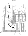
- Fig. 6 is a diagram showing schematically a flow of fuel and air in areas around the guide according to the first embodiment.
- the portion of the high-pressure air 101 that has not been used for the film cooling of the inner casing 10 flows through the first annular flow path 48 toward the fuel header 40.
- This portion of the high-pressure air 101 flows from the first annular flow path 48 into the supply flow path 41 and is supplied to the air holes 33A in the base plate 32A as the air jets 35.
- the high-pressure air 101 flowing near the surface of the bent portion 37B (hereinafter referred to as nearby air 104) is diverted along the surface of the bent portion 37B to be guided to the outside in the radial direction of the base plate 32A and, in particular, into the air hole 33A on the outermost periphery.
- Part of the high-pressure air 101 flowing through the first annular flow path 48 toward the fuel header 40 along the inner casing 10 collides with the wall portion 37A of the guide 37. This collision creates a stagnant zone in an area near the wall portion 37A.
- Pressure in the combustion chamber 50 is lower than pressure in the first annular flow path 48 (specifically, pressure is lower at an outlet side of the outer peripheral flow path 94 than at an inlet side of the outer peripheral flow path 94).
- This difference in pressure between the first annular flow path 48 and the combustion chamber 50 causes the high-pressure air 101 in the stagnant zone near the wall portion 37A to flow into the outer peripheral flow path 94 in a direction opposite to (e.g., 180°) a direction in which the high-pressure air 101 flows through the first annular flow path 48.
- the high-pressure air 101 that has flowed into the outer peripheral flow path 94 will hereinafter be referred to as auxiliary air 105.
- the auxiliary air 105 passes through the hole in the spring seal 14 and is injected inwardly in the radial direction to the combustion chamber 50 via the through hole 92 formed in the extension 93 of the swirl plate 32B.
- fuel supplied from the fuel system 200 to the fuel nozzle 91 via the fuel header 40 is injected from an injection port at the leading end of the fuel nozzle 91 and flows as the fuel jet 34 into the air hole 33A.
- the fuel jet 34 that has flowed into the air hole 33A flows through the air hole 33A, while being rapidly mixed with the air jet 35, and flows as a mixture into the air hole 33B formed in the swirl plate 32B.
- the air hole 33B is formed into a tube that is inclined circumferentially at the predetermined angle ⁇ ° with respect to the air hole 33A (oblique circular cylinder tube). A force component in a swirl direction is thus given to the mixture that flows through the air hole 33B to thereby form a circulating flow.
- the air hole 33B communicates with the combustion chamber 50, the flow path of the mixture considerably expands, so that mixing is promoted in the area near the second outlet.
- the mixture of the fuel jet 34 and the air jet 35 injected from the air hole 33B is injected as a fuel-air pre-mixture 36 into, and burned in, the combustion chamber 50.
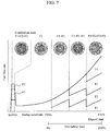
- Fig. 7 is a diagram showing fuel staging in the combustor according to the first embodiment.
- the abscissa axis represents elapsed time and the ordinate axis represents fuel flow rate.
- the F1 to F3 fuels are supplied to the first to third burner portions 5A to 5C from the fuel system 200 via the first to third fuel systems 20A to 20C. Specifically, the fuel is injected from the fuel nozzles 91 disposed in the first to sixth rows of the burner 5. Meanwhile, the F4 fuel is not supplied to the fourth burner portion 5D and thus no fuel is injected from the fuel nozzles 91 disposed in the seventh and eighth rows of the burner 5.
- the turbine 3 When the turbine 3 is accelerated up to a rated speed thereof, power generation is started to increase gas turbine load.
- the F2 fuel, the F3 fuel, and the F4 fuel are additionally supplied to the second burner portion 5B, the third burner portion 5C, and the fourth burner portion 5D, in sequence, to thereby expand a fuel supply range to the fifth row, the sixth row, and the seventh and eighth rows of the burner 5 in a stepwise fashion, so that the fuel-air ratio in the burner 5 falls within a stable combustion range.
- the gas turbine load reaches a full speed full load (FSFL) state in a combustion state in which fuel is supplied to all of the first to fourth burner portions 5A to 5D and fuel is injected from all of the first to eighth rows.
- FSFL full speed full load
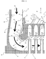
- Fig. 10 is a diagram showing schematically the flow of fuel and air in areas around a guide according to a second embodiment.
- the upper side as viewed from the viewer is the air upstream side and the lower side as viewed from the viewer is the air downstream side.
- like or corresponding parts are identified by the same reference numerals as those used in the first embodiment and descriptions for those parts will be omitted as appropriate.
- a combustor according to the second embodiment differs from the combustor 2 according to the first embodiment in that a first annular flow path 48 includes a flow path expanded portion 44.
- the combustor in the second embodiment is configured identically to the combustor 2 in the first embodiment in other respects.
- a portion of the outer casing 11 extending from a position opposed to an end on the combustion gas downstream side of an extension 93 of an air hole plate 32 across the first annular flow path 48 to a position opposed to an apex of a guide 37 is inclined outwardly in the radial direction toward the air downstream side, thereby forming the flow path expanded portion 44.
- the above-described portion of the outer casing 11 will hereinafter be referred to as an inclined portion 11A.
- the inclined portion 11A is a linear inclined surface having a mild gradient in a sectional view of the air hole plate 32.
- the inclined portion 11A is formed such that a distance between a central axis of the air hole plate 32 and the inclined portion 11A increases toward the air downstream side.
- the first annular flow path 48 has a flow path area increasing toward the air downstream side.
- A1 be the flow path area of the first annular flow path 48 between the outer casing 11 and an inner casing 10 on the air upstream side of the inclined portion 11A and let A2 be the flow path area of the first annular flow path 48 at the apex of the guide 37.
- the flow path expanded portion 44 is formed such that A1 ⁇ A2 is satisfied.
- the inclined portion 11A may be any portion other than the portion described above when the flow path expanded portion 44 is formed such that A1 ⁇ A2 is satisfied.
- the second embodiment achieves the following effects in addition to the effects similar to those achieved by the first embodiment.
- the guide 37 at the apex has an outside diameter greater than an outside diameter of the inner casing 10, so that A2 is smaller than A1 (A2 ⁇ A1).
- A2 is smaller than A1 (A2 ⁇ A1).
- the flow path expanded portion 44 is formed such that A2 is equal to or greater than A1 (A1 ⁇ A2). This arrangement prevents the flow velocity of the high-pressure air 101 from increasing when the high-pressure air 101 flows past the apex of the guide 37, so that the total pressure loss can be prevented from increasing.
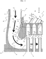
- Fig. 11 is a diagram showing schematically the flow of fuel and air in areas around a guide according to a third embodiment.
- the upper side as viewed from the viewer is the air upstream side and the lower side as viewed from the viewer is the air downstream side.
- like or corresponding parts are identified by the same reference numerals as those used in the second embodiment and descriptions for those parts will be omitted as appropriate.
- a combustor according to the third embodiment differs from the combustor according to the second embodiment in that an outer casing 11 includes a curved surface portion 45.
- the combustor in the third embodiment is configured identically to the combustor in the second embodiment in other respects.
- the curved surface portion 45 is curved into a recessed shape so as to follow a profile of a bent portion 37B of a guide 37.
- the curved surface portion 45 arcuately extends from a flow path expanded portion 44 to a fuel header 40 to thereby connect therebetween.
- the curved surface portion 45 is formed into a curved surface smoothly connecting between the flow path expanded portion 44 and the fuel header 40.
- the third embodiment has been described for an exemplary configuration in which the outer casing 11 includes the curved surface portion 45.
- the fuel header 40 may include the curved surface portion 45.
- the third embodiment achieves the following effects in addition to the effects similar to those achieved by the second embodiment.
- the configuration in the third embodiment includes the recessed, curved surface portion 45 that arcuately extends from the flow path expanded portion 44 to the fuel header 40.
- This configuration allows the high-pressure air 101 flowing near the surface of the curved surface portion 45 to be guided along the curved surface portion 45 and smoothly diverted, so that the high-pressure air 101 flows into a supply flow path 41.
- a velocity distribution in the radial direction of the high-pressure air 101 that flows from a first annular flow path 48 into the supply flow path 41 can be equalized and the total pressure loss can be further reduced.
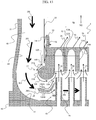
- Fig. 12 is a diagram showing schematically the flow of fuel and air in areas around a guide according to a fourth embodiment.
- the upper side as viewed from the viewer is the air upstream side and the lower side as viewed from the viewer is the air downstream side.
- like or corresponding parts are identified by the same reference numerals as those used in the third embodiment and descriptions for those parts will be omitted as appropriate.
- a combustor according to the fourth embodiment differs from the combustor according to the third embodiment in that a guide 37 includes a taper portion 37C.
- the combustor in the fourth embodiment is configured identically to the combustor in the third embodiment in other respects.
- the taper portion 37C is disposed between a wall portion 37A and a bent portion 37B and the wall portion 37A and the bent portion 37B are each smoothly connected to the taper portion 37C.
- This configuration results in taper portion 37C assuming a smooth connection between the wall portion 37A and the bent portion 37B.
- the bent portion 37B is formed so as to connect between the taper portion 37C and an air hole 33A on an outermost periphery in the radial direction of a base plate 32A.
- the taper portion 37C is inclined outwardly in the radial direction toward the air downstream side with respect to a central axis of an air hole plate 32. As a result, a distance between the taper portion 37C and the central axis of the air hole plate 32 increases toward the air downstream side.
- disposing the upwardly inclined taper portion 37C between the wall portion 37A and the bent portion 37B of the guide 37 allows the high-pressure air 101 to be mildly guided from the wall portion 37A to the bent portion 37B.
- the flow velocity of the high-pressure air 101 near the guide 37 can be prevented from increasing and the total pressure loss can be prevented from increasing.
- Fig. 13 is a diagram showing schematically the flow of fuel and air in areas around a guide according to a fifth embodiment.
- the upper side as viewed from the viewer is the air upstream side and the lower side as viewed from the viewer is the air downstream side.
- like or corresponding parts are identified by the same reference numerals as those used in the third embodiment and descriptions for those parts will be omitted as appropriate.
- a combustor according to the fifth embodiment differs from the combustor according to the third embodiment in a guide vane 38 included therein.
- the combustor in the fifth embodiment is configured identically to the combustor in the third embodiment in other respects.
- the guide vane 38 is disposed between a guide 37 in a first annular flow path 48 and a fuel header 40.
- the guide vane 38 includes a front edge portion 38A and a rear edge portion 38B.
- the guide vane 38 is disposed such that the rear edge portion 38B is disposed, with respect to the front edge portion 38A, on the inside in the radial direction of an air hole plate 32 and on the side of an air hole on an outermost periphery in the radial direction of the air hole plate 32.
- the guide vane 38 is disposed such that a ventral side surface (positive pressure surface, specifically, the recessed surface) thereof faces the air hole plate 32 and a dorsal side surface (negative pressure surface, specifically, the protruding surface) thereof faces the fuel header 40.
- the ventral side surface is curved to substantially follow the profile of a bent portion 37B.
- the guide vane 38 is configured to be a ring shape coaxial with the burner 5 as viewed from the axial direction of the burner 5.
- a plurality of guide vanes may nonetheless be disposed annularly.
- the guide vane 38 is disposed such that a distance between the guide vane 38 and an end on the air downstream side of the guide 37 in the axial direction of the burner 5 is substantially equal to a distance between the guide vane 38 and the fuel header 40.
- the position of the guide vane 38 between the end on the air downstream side of the guide 37 and the fuel header 40 is not, however, limiting.
- the fifth embodiment achieves the following effects in addition to the effects similar to those achieved by the third embodiment.
- the guide vane 38 is disposed between the guide 37 in the first annular flow path 48 and the fuel header 40.
- This arrangement allows outer peripheral side vane air 106B that flows along an outer peripheral side (dorsal side) to be guided inwardly in the radial direction of the burner 5, while guiding inner peripheral side vane air 106A that flows along an inner peripheral side (ventral side) of the guide vane 38 outwardly in the radial direction of a base plate 32A, or, in particular, the air hole 33A on the outermost periphery.
- a deviation in the air flow rate supplied to the air hole 33A can be further minimized, so that maintenance of stable combustion and reduction in the amount of NOx emissions can be promoted.
- Fig. 14 is a diagram showing schematically the flow of fuel and air in areas around a guide according to a sixth embodiment.
- the upper side as viewed from the viewer is the air upstream side and the lower side as viewed from the viewer is the air downstream side.
- like or corresponding parts are identified by the same reference numerals as those used in the first embodiment and descriptions for those parts will be omitted as appropriate.
- a combustor according to the sixth embodiment differs from the combustor according to the first embodiment in a multi-hole plate (connecting member) 43 included in place of the support 15.
- the combustor in the sixth embodiment is configured identically to the combustor in the first embodiment in other respects.
- the multi-hole plate 43 is a short pipe member coaxial with an inner casing 10.
- the multi-hole plate 43 is disposed so as to separate a first annular flow path 48 from a supply flow path 41.
- the multi-hole plate 43 connects an end on the air downstream side of a guide 37 with a fuel header 40.
- an air hole plate 32 is mounted on the fuel header 40 via the multi-hole plate 43.
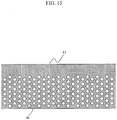
- Fig. 15 is a cross-sectional view taken along the arrowed line XV-XV of Fig. 14 .
- the multi-hole plate 43 has a plurality of circular communication holes 46 arrayed in rows extending in the axial direction and the circumferential direction as shown in Fig. 15 .
- the communication holes 46 provide communication between the first annular flow path 48 and the supply flow path 41.
- the high-pressure air 101 that flows through the first annular flow path 48 passes through the communication holes 46 to enter the supply flow path 41.
- the multi-hole plate 43 is disposed such that the communication holes 46 are disposed near the end on the air downstream side of the guide 37.
- the high-pressure air 101 nearby air 104 that flows along the surface of a bent portion 37B of the guide 37 enters the supply flow path 41 through these communication holes 46.
- the sixth embodiment achieves the following effects in addition to the effects similar to those achieved by the first embodiment.
- the multi-hole plate 43 having a plurality of communication holes 46 is disposed so as to separate the first annular flow path 48 from the supply flow path 41.
- the high-pressure air 101 flowing through the first annular flow path 48 is thus smoothed by the communication holes 46 before entering the supply flow path 41.
- the nearby air 104 can be guided outwardly in the radial direction of a base plate 32A, or in particular, to an air hole 33A on the outermost periphery more efficiently.
- a deviation in the flow rate in the circumferential direction of a burner 5 of the high-pressure air 101 that flows from the first annular flow path 48 into the supply flow path 41 can be further minimized, so that combustion stability can be enhanced and the amount of NOx emissions can be further reduced.
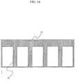
- Fig. 16 is a diagram showing a modification of the multi-hole plate according to the sixth embodiment.
- a multi-window support (connecting member) 51 as shown in Fig. 16 may be provided.
- the multi-window support 51 has a plurality of rectangular windows 52 arrayed in the circumferential direction.
- the windows 52 are arrayed in one row in the axial direction and the windows 52 are each formed to have an opening area greater than each of the communication holes 46.
- the multi-window support 51 incorporated in place of the multi-hole plate 43, the high-pressure air 101 flowing through the first annular flow path 48 is smoothed, so that the effects similar to those achieved by the sixth embodiment can be achieved.
- the windows 52 are each formed to have an opening area greater than an opening area of each of the communication holes 46. This arrangement allows the multi-window support 51 to decrease differential pressure between the air upstream side and the air downstream side of the multi-window support 51 than in the multi-hole plate 43, so that the total pressure loss can be prevented from increasing.
- the multi-hole plate 43 and the multi-window support 51 shown in Figs. 14 , 15 and 16 can be applied to the gas turbine combustors according to first to fifth embodiments.
- Fig. 17 is a diagram showing schematically the flow of fuel and air in areas around a guide according to a seventh embodiment.
- the upper side as viewed from the viewer is the air upstream side and the lower side as viewed from the viewer is the air downstream side.
- like or corresponding parts are identified by the same reference numerals as those used in the sixth embodiment and descriptions for those parts will be omitted as appropriate.
- a combustor according to the seventh embodiment differs from the combustor according to the sixth embodiment in that the multi-hole plate 43 is disposed at a position different from the position at which the multi-hole plate 43 in the sixth embodiment is disposed.
- the combustor in the seventh embodiment is configured identically to the combustor in the sixth embodiment in other respects.
- an outer casing 11 includes a first outer casing 11B and a second outer casing 11C.
- the first outer casing 11B is disposed such that an end thereof on the air downstream side faces an apex of a guide 37 across a first annular flow path 48.
- the second outer casing 11C is disposed such that an end thereof on the air upstream side connects with the end on the air downstream side of the first outer casing 11B and an end thereof on the air downstream side connects with a fuel header 40.
- a space 11D is formed between the end on the air downstream side of the first outer casing 11B and the end on the air upstream side of the second outer casing 11C.
- the multi-hole plate 43 has a lower end portion (the end on the side close to an air hole plate 32) connecting with the apex of the guide 37 and an upper end portion (the end spaced away from the air hole plate 32) inserted in the space 11D.
- the multi-hole plate 43 is a disc-shaped plate coaxial with an inner casing 10, connecting the apex of the guide 37 with the outer casing 11.
- the air hole plate 32 is mounted on the outer casing 11 via the multi-hole plate 43.
- the multi-hole plate 43 is formed into a doughnut-shaped disc coaxial with a burner 5.
- the configuration in which the multi-hole plate 43 is disposed so as to connect between the apex of the guide 37 and the outer casing 11 as in the seventh embodiment can achieve the effects similar to those achieved by the sixth embodiment. Additionally, the above-described multi-window support 51 may be applied in place of the multi-hole plate 43 also in the seventh embodiment. In this case, the effects similar to those achieved by the modification described above can be achieved.
- the multi-hole plate 43 shown in Fig. 17 can be applied to the gas turbine combustors according to first to fifth embodiments.
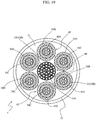
- Fig. 18 is a sectional view of a combustor according to an eighth embodiment.
- Fig. 19 is a view of an air hole plate of the combustor according to the eighth embodiment as viewed from the combustion gas downstream side.
- like or corresponding parts are identified by the same reference numerals as those used in the first embodiment and descriptions for those parts will be omitted as appropriate.
- a combustor 201 according to the eighth embodiment is what is called a multi-injection gas turbine combustor that includes a plurality of burners disposed at a combustion portion, each of the burners including a plurality of fuel nozzles and a plurality of air holes arrayed concentrically.
- the combustor 201 includes one burner (pilot burner) 49 and six burners (main burners) 42.
- the pilot burner 49 is disposed at a center of the combustion portion coaxially with the combustor 201.
- the main burners 42 are disposed around the pilot burner 49.
- the combustor 201 has a multi-burner configuration including seven burners.
- the pilot burner 49 and the main burners 42 share an air hole plate 32.
- the pilot burner 49 and the main burners 42 are each partitioned into a plurality of (three in the eighth embodiment) concentric annular rows.
- the annular rows are referred to, as appropriate, as a first row, a second row, and a third row from the inner peripheral side toward the outer peripheral side.
- the pilot burner 49 includes a plurality of fuel nozzles 91 and part of the air hole plate 32. Specifically, the fuel nozzles 91 are arrayed concentrically into the first to third rows.
- the part of the air hole plate 32 has a plurality of air holes 33 (33A and 33B) formed to be associated with the respective fuel nozzles 91.
- the main burners 42 each include a plurality of fuel nozzles 91 and another part of the air hole plate 32. Specifically, the fuel nozzles 91 are arrayed concentrically into the first to third rows.
- the other part of the air hole plate 32 has a plurality of air holes 33 (33A and 33B) formed to be associated with the respective fuel nozzles 91.
- a first fuel system 20A is connected with a first burner portion 50A that constitutes the first to third rows of the pilot burner 49.
- a second fuel system 20B is connected with second burner portions 50B that constitute the first rows of two main burners 42 out of the six main burners 42.
- a third fuel system 20C is connected with third burner portions 50C that constitute the first rows of other four main burners 42 out of the six main burners 42.
- a fourth fuel system 20D is connected with fourth burner portions 50D that constitute the second and third rows of the six main burners 42.
- the portion of the high-pressure air 101 that has not been used for the film cooling of the inner casing 10 flows from the first annular flow path 48 into a supply flow path 41 and is supplied to the air holes 33A in the base plate 32A as air jets 35.
- Fuels injected from the fuel nozzles 91 are mixed with the air jets 35 and injected as fuel-air pre-mixtures from the air holes 33B, so that swirl flows 60 are formed downstream of the pilot burner 49 and the main burners 42, respectively.
- the swirl flows 60 generate circulating flows 61, so that flame surfaces 62 are formed.
- fuels supplied to the first to fourth burner portions 50A to 50D can be individually regulated, thereby achieve fuel staging.
- the effects achieved by the first embodiment can be achieved by the multi-injection gas turbine combustor configured as in the eighth embodiment.
- the first embodiment allows the high-pressure air 101 (nearby air 104) that flows near the surface of the bent portion 37B to be guided to the outside in the radial direction of the base plate 32A, or in particular, the air hole 33 on the outermost periphery
- the eighth embodiment allows the nearby air 104 to be guided to the air holes 33 on the side adjacent to the guide 37 of the air holes 33 disposed on the outermost peripheral rows (third rows) of the main burners 42, or in particular, the air holes closest to the guide 37.
- This enables supply of the high-pressure air 101 uniformly to the air holes in the pilot burner 49 and the main burners 42.
- a deviation in the flow rate in the circumferential direction of a burner 5 of the high-pressure air 101 supplied to the air holes 33 in the pilot burner 49 and the main burners 42 can be minimized, so that combustion stability and low NOx combustion can both be achieved.
- the multi-injection gas turbine combustor shown in Figs. 18 and 19 can be applied as the gas turbine combustors according to second to seventh embodiments as well as the first embodiment.
- the air holes 33 in the air hole plate 32 have been described to be formed circumferentially along the respective annular rows. It is, however, the object of the present invention to provide a combustor capable of achieving an essential effect of reducing a deviation in the air flow rate supplied to each air hole.
- the air holes 33 do not, therefore, necessarily have to be disposed circumferentially along the respective annular rows, if the essential effect can be achieved.
- the air holes 33 may be formed in part of the annular rows on the outer peripheral side.
- the first to fourth embodiments have been described for the configuration in which the air holes 33A and 33B are formed in the first to eighth rows arranged concentrically in the base plate 32A and the swirl plate 32B.
- the number of air hole rows formed in the base plate 32A and the swirl plate 32B does not, however, have to be eight, if the essential effect of the present invention described above can be achieved.
- the number of air hole rows formed in the base plate 32A and the swirl plate 32B may be seven or less, or nine or more.
- each of the embodiments described above has been described for the configuration in which the leading ends of the fuel nozzles 91 are spaced away from the first inlets of the air holes 33A in the base plate 32A.
- the above-described configuration is not necessarily required, if the essential effect of the present invention described above can be achieved.
- the leading ends of the fuel nozzles 91 may be inserted in the air holes 33.
- an area of each of the first inlets of the air holes 33A decreases to allow the air jet 35 to build up a flow velocity thereof, so that mixing of fuel injected from the fuel nozzle 91 and air can be further promoted.
- the leading end of the fuel nozzle 91 is shaped into a simple cylindrical form.
- the cylindrical shape of the leading end of the fuel nozzle 91 is not necessarily required, if the essential effect of the present invention described above can be achieved.
- the leading end of the fuel nozzle 91 may have a protrusion that protrudes radially therefrom. The protrusion generates a swirl flow in the fuel injected from the fuel nozzle 91, to thereby further promote mixing of fuel and air.
- the leading end of the fuel nozzle 91 may have a plurality of fuel injection ports. This configuration enhances initial dispersion of fuel to thereby further promote mixing of fuel and air.
Landscapes
- Engineering & Computer Science (AREA)
- Chemical & Material Sciences (AREA)
- Combustion & Propulsion (AREA)
- Mechanical Engineering (AREA)
- General Engineering & Computer Science (AREA)
Claims (8)
- Unité de combustion de turbine à gaz (2), comprenant :un boîtier intérieur (10) qui définit à l'intérieur une chambre de combustion (50) ;un boîtier extérieur (11) disposé de manière à couvrir le boîtier intérieur (10) ;un trajet d'écoulement annulaire (48) disposé entre le boîtier intérieur (10) et le boîtier extérieur (11), le trajet d'écoulement annulaire (48) permettant à de l'air sous haute pression (101) de s'écouler à travers celui-ci ;un collecteur de carburant (40) disposé en aval du boîtier extérieur (11) dans une direction d'écoulement de l'air sous haute pression (101) ;une pluralité de buses de carburant (91) supportées concentriquement sur le collecteur de carburant (40) ;une plaque à trous d'air (32) disposée en aval des buses de carburant (91) dans une direction d'écoulement du carburant, la plaque à trous d'air (32) ayant une pluralité de trous d'air (33) associés aux buses de carburant respective (91) ;caractérisée en ce que l'unité de combustion de turbine à gaz (2) comprend :un guide (37) incluant une portion de paroi (37A) qui se projette depuis une surface périphérique extérieure de la plaque à trous d'air (32) plus loin qu'un côté périphérique extérieur du boîtier intérieur (10) et une portion incurvée (37B) formée dans une forme convexe qui se projette vers le boîtier extérieur (11) et le collecteur de carburant (40) et reliée de manière arquée à ceux de la pluralité de trous d'air (33) qui sont agencés sur une périphérie tout à fait extérieure dans une direction radiale de la plaque à trous d'air (32) ; etun trajet d'écoulement périphérique extérieur (94) défini entre la surface périphérique extérieure de la plaque à trous d'air (32) et le boîtier intérieur (10), le trajet d'écoulement périphérique extérieur (94) alimentant de l'air sous haute pression (101) dans une portion périphérique extérieure d'une partie de la chambre de combustion (50) sur un côté de la plaque à trous d'air (32).
- Unité de combustion de turbine à gaz (2) selon la revendication 1, comprenant en outre :
un joint à ressort (14) disposé entre la surface périphérique extérieure de la plaque à trous d'air (32) et le boîtier intérieur (10), dans laquelle le joint à ressort (14) comporte un trou formé dans lui-même, à travers lequel l'air sous haute pression (101) peut circuler. - Unité de combustion de turbine à gaz (2) selon la revendication 1 ou 2, dans laquelle :la plaque à trous d'air (32) inclut une extension (93) disposée sur une portion périphérique extérieure d'elle-même, l'extension (93) s'étendant depuis une surface de paroi sur un côté adjacent à la chambre de combustion (50) en aval dans une direction d'écoulement du gaz de combustion (102), etle trajet d'écoulement périphérique extérieur (94) a une sortie formée pour passer à travers l'extension.
- Unité de combustion de turbine à gaz (2) selon l'une au moins des revendications 1 à 3, dans laquelle le trajet d'écoulement annulaire (48) inclut une portion agrandie de trajet d'écoulement ayant une superficie de trajet d'écoulement qui augmente en direction d'un côté aval dans la direction d'écoulement de l'air sous haute pression (101).
- Unité de combustion de turbine à gaz (2) selon l'une au moins des revendications 1 à 4, dans laquelle le boîtier extérieur (11) ou le collecteur de carburant (40) inclut une portion de surface incurvée (45) incurvée pour suivre un profil de la portion cintrée (37B).
- Unité de combustion de turbine à gaz (2) selon l'une au moins des revendications 1 à 5, comprenant en outre :
une aube de guidage (38) disposée entre le guide (37) dans le trajet d'écoulement annulaire (48) et le collecteur de carburant (40), dans laquelle l'aube de guidage (38) est disposée de telle façon qu'une portion de bordure arrière (38B) de celle-ci est disposée, par rapport à une portion de bordure avant (38A) de celle-ci, sur l'intérieur dans la direction radiale de la plaque à trous d'air (32) et sur un côté du trou d'air sur la périphérie la plus extérieure de la plaque à trous d'air (32). - Unité de combustion de turbine à gaz (2) selon l'une au moins des revendications 1 à 6, comprenant en outre :un trajet d'écoulement d'alimentation (41) disposé entre la plaque à trous d'air (32) et le collecteur de carburant (40) ; etun élément de connexion annulaire qui sépare le trajet d'écoulement annulaire (48) vis-à-vis du trajet d'écoulement d'alimentation (41), dans laquellel'élément de connexion annulaire a un trou de communication qui assure une communication entre le trajet d'écoulement annulaire (48) et le trajet d'écoulement d'alimentation (41).
- Installation de turbine à gaz (1000), comprenant :un compresseur (1) qui comprime de l'air ;une unité de combustion de turbine à gaz (2) selon l'une au moins des revendications 1 à 7, l'unité de combustion de turbine à gaz (2) mélangeant de l'air sous haute pression (101) alimenté depuis le compresseur (1) avec du carburant pour faire brûler un mélange résultant ; etune turbine (3) entraînée en rotation par les gaz de combustion fournis depuis l'unité de combustion de turbine à gaz (2).
Applications Claiming Priority (1)
| Application Number | Priority Date | Filing Date | Title |
|---|---|---|---|
| JP2015178176A JP6422412B2 (ja) | 2015-09-10 | 2015-09-10 | ガスタービン燃焼器 |
Publications (2)
| Publication Number | Publication Date |
|---|---|
| EP3141817A1 EP3141817A1 (fr) | 2017-03-15 |
| EP3141817B1 true EP3141817B1 (fr) | 2019-12-04 |
Family
ID=56888972
Family Applications (1)
| Application Number | Title | Priority Date | Filing Date |
|---|---|---|---|
| EP16187715.4A Active EP3141817B1 (fr) | 2015-09-10 | 2016-09-07 | Chambre de combustion de turbine à gaz |
Country Status (5)
| Country | Link |
|---|---|
| US (1) | US20170074519A1 (fr) |
| EP (1) | EP3141817B1 (fr) |
| JP (1) | JP6422412B2 (fr) |
| KR (1) | KR101867690B1 (fr) |
| CN (1) | CN106524222B (fr) |
Cited By (1)
| Publication number | Priority date | Publication date | Assignee | Title |
|---|---|---|---|---|
| RU2751828C1 (ru) * | 2019-12-16 | 2021-07-19 | Мицубиси Пауэр, Лтд. | Сжигающее устройство газотурбинной установки |
Families Citing this family (22)
| Publication number | Priority date | Publication date | Assignee | Title |
|---|---|---|---|---|
| KR101838822B1 (ko) * | 2013-10-18 | 2018-03-14 | 미츠비시 쥬고교 가부시키가이샤 | 연료 분사기 |
| JP6779098B2 (ja) * | 2016-10-24 | 2020-11-04 | 三菱パワー株式会社 | ガスタービン燃焼器 |
| KR102010646B1 (ko) | 2017-07-04 | 2019-08-13 | 두산중공업 주식회사 | 터닝 가이드, 연료 노즐, 연료 노즐 조립체 및 이를 포함하는 가스 터빈 |
| CN107676815B (zh) * | 2017-09-05 | 2020-03-10 | 中国联合重型燃气轮机技术有限公司 | 燃烧器和具有该燃烧器的燃气轮机 |
| CN107702144B (zh) * | 2017-09-05 | 2020-03-10 | 中国联合重型燃气轮机技术有限公司 | 燃烧器和具有该燃烧器的燃气轮机 |
| JP6945468B2 (ja) * | 2018-02-06 | 2021-10-06 | 三菱パワー株式会社 | ガスタービン燃焼器、ガスタービン及びガスタービン燃焼器の制御方法 |
| KR102068305B1 (ko) | 2018-03-19 | 2020-01-20 | 두산중공업 주식회사 | 연소기 및 이를 포함하는 가스 터빈 |
| KR102101488B1 (ko) * | 2018-08-17 | 2020-04-16 | 두산중공업 주식회사 | 연소기 및 이를 포함하는 가스 터빈 |
| JP7132096B2 (ja) * | 2018-11-14 | 2022-09-06 | 三菱重工業株式会社 | ガスタービン燃焼器 |
| JP7130545B2 (ja) * | 2018-12-20 | 2022-09-05 | 三菱重工業株式会社 | ガスタービン燃焼器、ガスタービン及びガスタービン燃焼器の製造方法 |
| JP7112342B2 (ja) * | 2019-01-25 | 2022-08-03 | 三菱重工業株式会社 | ガスタービン燃焼器及びガスタービン |
| CN111829012B (zh) * | 2019-04-17 | 2022-04-08 | 中国航发湖南动力机械研究所 | 火焰筒 |
| KR102097029B1 (ko) * | 2019-05-13 | 2020-04-03 | 두산중공업 주식회사 | 연소기 및 이를 포함하는 가스 터빈 |
| JP7270517B2 (ja) * | 2019-10-01 | 2023-05-10 | 三菱重工業株式会社 | ガスタービン燃焼器 |
| CN113531584B (zh) * | 2020-04-15 | 2023-05-23 | 上海慕帆动力科技有限公司 | 燃气轮机的燃烧装置 |
| KR102340397B1 (ko) * | 2020-05-07 | 2021-12-15 | 두산중공업 주식회사 | 연소기 및 이를 포함하는 가스 터빈 |
| CN112197294B (zh) * | 2020-09-21 | 2022-04-01 | 中国航发沈阳发动机研究所 | 一种整流板 |
| CN114294680B (zh) * | 2021-12-29 | 2023-07-04 | 哈尔滨工业大学 | 一种中心分级燃气轮机微预混燃烧室 |
| CN115930260B (zh) * | 2022-11-15 | 2025-01-28 | 中国航发湖南动力机械研究所 | 一种辅助动力装置的引气结构及航空发动机 |
| EP4411235B1 (fr) * | 2023-02-02 | 2025-08-27 | Pratt & Whitney Canada Corp. | Moteur à turbine à gaz à hydrogène avec anneau d'injecteur et alimentation étagée de carburant |
| US11867392B1 (en) * | 2023-02-02 | 2024-01-09 | Pratt & Whitney Canada Corp. | Combustor with tangential fuel and air flow |
| CN121013961A (zh) * | 2023-04-26 | 2025-11-25 | 三菱重工业株式会社 | 喷燃器集合体、燃气轮机燃烧器及燃气轮机 |
Family Cites Families (21)
| Publication number | Priority date | Publication date | Assignee | Title |
|---|---|---|---|---|
| JPH11230549A (ja) * | 1998-02-12 | 1999-08-27 | Hitachi Ltd | ガスタービン燃焼器 |
| JP3960166B2 (ja) * | 2001-08-29 | 2007-08-15 | 株式会社日立製作所 | ガスタービン燃焼器およびガスタービン燃焼器の運転方法 |
| US7770395B2 (en) * | 2006-02-27 | 2010-08-10 | Mitsubishi Heavy Industries, Ltd. | Combustor |
| US8671658B2 (en) * | 2007-10-23 | 2014-03-18 | Ener-Core Power, Inc. | Oxidizing fuel |
| KR101318553B1 (ko) * | 2009-08-13 | 2013-10-16 | 미츠비시 쥬고교 가부시키가이샤 | 연소기 |
| ITBO20090624A1 (it) * | 2009-09-29 | 2011-03-30 | Simex Engineering Srl | Sistema di accoppiamento fra utensili e portautensili di macchine e attrezzature frantumatrici |
| US8371123B2 (en) * | 2009-10-28 | 2013-02-12 | General Electric Company | Apparatus for conditioning airflow through a nozzle |
| JP5356340B2 (ja) * | 2010-09-06 | 2013-12-04 | 株式会社日立製作所 | ガスタービン燃焼器の制御装置及びガスタービン燃焼器の制御方法 |
| US9719419B2 (en) * | 2011-03-16 | 2017-08-01 | Mitsubishi Heavy Industries, Ltd. | Gas turbine combustor with top hat nozzle arrangements |
| US8695351B2 (en) * | 2011-05-05 | 2014-04-15 | General Electric Company | Hula seal with preferential cooling having spring fingers and/or adjacent slots with different widths |
| US8397514B2 (en) * | 2011-05-24 | 2013-03-19 | General Electric Company | System and method for flow control in gas turbine engine |
| JP5507504B2 (ja) * | 2011-07-19 | 2014-05-28 | 株式会社日立製作所 | ガスタービン燃焼器 |
| US8950188B2 (en) * | 2011-09-09 | 2015-02-10 | General Electric Company | Turning guide for combustion fuel nozzle in gas turbine and method to turn fuel flow entering combustion chamber |
| US9297532B2 (en) * | 2011-12-21 | 2016-03-29 | Siemens Aktiengesellschaft | Can annular combustion arrangement with flow tripping device |
| US20130269359A1 (en) * | 2012-04-16 | 2013-10-17 | General Electric Company | Combustor flow sleeve with supplemental air supply |
| US8973372B2 (en) * | 2012-09-05 | 2015-03-10 | Siemens Aktiengesellschaft | Combustor shell air recirculation system in a gas turbine engine |
| JP5972125B2 (ja) * | 2012-09-12 | 2016-08-17 | 三菱日立パワーシステムズ株式会社 | ガスタービン燃焼器 |
| JP5908379B2 (ja) * | 2012-09-24 | 2016-04-26 | 三菱日立パワーシステムズ株式会社 | ガスタービン燃焼器 |
| CN105229379B (zh) * | 2013-03-13 | 2017-06-13 | 三菱日立电力系统株式会社 | 燃气涡轮燃烧器 |
| JP6004976B2 (ja) * | 2013-03-21 | 2016-10-12 | 三菱重工業株式会社 | 燃焼器及びガスタービン |
| EP2784393A1 (fr) * | 2013-03-26 | 2014-10-01 | Siemens Aktiengesellschaft | Chambre de combustion d'une turbine à gaz avec des clapets d'air secondaire |
-
2015
- 2015-09-10 JP JP2015178176A patent/JP6422412B2/ja active Active
-
2016
- 2016-08-30 US US15/250,992 patent/US20170074519A1/en not_active Abandoned
- 2016-09-05 KR KR1020160113692A patent/KR101867690B1/ko active Active
- 2016-09-06 CN CN201610806235.9A patent/CN106524222B/zh active Active
- 2016-09-07 EP EP16187715.4A patent/EP3141817B1/fr active Active
Non-Patent Citations (1)
| Title |
|---|
| None * |
Cited By (1)
| Publication number | Priority date | Publication date | Assignee | Title |
|---|---|---|---|---|
| RU2751828C1 (ru) * | 2019-12-16 | 2021-07-19 | Мицубиси Пауэр, Лтд. | Сжигающее устройство газотурбинной установки |
Also Published As
| Publication number | Publication date |
|---|---|
| KR101867690B1 (ko) | 2018-06-15 |
| KR20170031048A (ko) | 2017-03-20 |
| US20170074519A1 (en) | 2017-03-16 |
| EP3141817A1 (fr) | 2017-03-15 |
| JP6422412B2 (ja) | 2018-11-14 |
| CN106524222B (zh) | 2020-04-03 |
| JP2017053276A (ja) | 2017-03-16 |
| CN106524222A (zh) | 2017-03-22 |
Similar Documents
| Publication | Publication Date | Title |
|---|---|---|
| EP3141817B1 (fr) | Chambre de combustion de turbine à gaz | |
| JP4177812B2 (ja) | タービンエンジンの燃料ノズル | |
| EP2065645B1 (fr) | Brûleur et chambre de combustion de turbine à gaz | |
| EP3067625B1 (fr) | Chambre de combustion de turbine à gaz, turbine à gaz et procédé | |
| EP3320268B1 (fr) | Brûleur pour turbine à gaz et procédé d'exploitation du brûleur | |
| EP2309188B1 (fr) | Dispositif de combustion et procédé de commande de celui-ci | |
| JP7245150B2 (ja) | ガスタービン燃焼器 | |
| CN103062796B (zh) | 燃烧器以及用于调整穿过燃烧器的流的方法 | |
| CN101377305A (zh) | 带径向分级流通道的预混合器和混合空气及燃气的方法 | |
| CN102330978A (zh) | 耐火焰副燃料喷嘴 | |
| JP2011196681A (ja) | 予混合一次燃料ノズルアセンブリを有する燃焼器 | |
| JP2017172953A (ja) | 軸方向多段型燃料噴射器アセンブリ | |
| EP3102877B1 (fr) | Chambre de combustion | |
| JP2015096794A (ja) | ガスタービン燃焼器 | |
| CN117120776A (zh) | 用于燃气涡轮机的燃烧室 | |
| CN102356279B (zh) | 尤其用于燃气轮机的燃烧器的工作方法和燃烧器 | |
| US20180299129A1 (en) | Combustor for a gas turbine | |
| JP2016023916A (ja) | ガスタービン燃焼器 | |
| KR102164621B1 (ko) | 연료 노즐 어셈블리 및 이를 포함하는 가스 터빈용 연소기 |
Legal Events
| Date | Code | Title | Description |
|---|---|---|---|
| PUAI | Public reference made under article 153(3) epc to a published international application that has entered the european phase |
Free format text: ORIGINAL CODE: 0009012 |
|
| STAA | Information on the status of an ep patent application or granted ep patent |
Free format text: STATUS: REQUEST FOR EXAMINATION WAS MADE |
|
| 17P | Request for examination filed |
Effective date: 20170131 |
|
| AK | Designated contracting states |
Kind code of ref document: A1 Designated state(s): AL AT BE BG CH CY CZ DE DK EE ES FI FR GB GR HR HU IE IS IT LI LT LU LV MC MK MT NL NO PL PT RO RS SE SI SK SM TR |
|
| AX | Request for extension of the european patent |
Extension state: BA ME |
|
| GRAP | Despatch of communication of intention to grant a patent |
Free format text: ORIGINAL CODE: EPIDOSNIGR1 |
|
| STAA | Information on the status of an ep patent application or granted ep patent |
Free format text: STATUS: GRANT OF PATENT IS INTENDED |
|
| INTG | Intention to grant announced |
Effective date: 20190705 |
|
| GRAS | Grant fee paid |
Free format text: ORIGINAL CODE: EPIDOSNIGR3 |
|
| GRAA | (expected) grant |
Free format text: ORIGINAL CODE: 0009210 |
|
| STAA | Information on the status of an ep patent application or granted ep patent |
Free format text: STATUS: THE PATENT HAS BEEN GRANTED |
|
| AK | Designated contracting states |
Kind code of ref document: B1 Designated state(s): AL AT BE BG CH CY CZ DE DK EE ES FI FR GB GR HR HU IE IS IT LI LT LU LV MC MK MT NL NO PL PT RO RS SE SI SK SM TR |
|
| REG | Reference to a national code |
Ref country code: GB Ref legal event code: FG4D |
|
| REG | Reference to a national code |
Ref country code: CH Ref legal event code: EP |
|
| REG | Reference to a national code |
Ref country code: AT Ref legal event code: REF Ref document number: 1209879 Country of ref document: AT Kind code of ref document: T Effective date: 20191215 |
|
| REG | Reference to a national code |
Ref country code: DE Ref legal event code: R096 Ref document number: 602016025405 Country of ref document: DE |
|
| REG | Reference to a national code |
Ref country code: IE Ref legal event code: FG4D |
|
| REG | Reference to a national code |
Ref country code: NL Ref legal event code: MP Effective date: 20191204 |
|
| REG | Reference to a national code |
Ref country code: LT Ref legal event code: MG4D |
|
| PG25 | Lapsed in a contracting state [announced via postgrant information from national office to epo] |
Ref country code: NO Free format text: LAPSE BECAUSE OF FAILURE TO SUBMIT A TRANSLATION OF THE DESCRIPTION OR TO PAY THE FEE WITHIN THE PRESCRIBED TIME-LIMIT Effective date: 20200304 Ref country code: GR Free format text: LAPSE BECAUSE OF FAILURE TO SUBMIT A TRANSLATION OF THE DESCRIPTION OR TO PAY THE FEE WITHIN THE PRESCRIBED TIME-LIMIT Effective date: 20200305 Ref country code: FI Free format text: LAPSE BECAUSE OF FAILURE TO SUBMIT A TRANSLATION OF THE DESCRIPTION OR TO PAY THE FEE WITHIN THE PRESCRIBED TIME-LIMIT Effective date: 20191204 Ref country code: BG Free format text: LAPSE BECAUSE OF FAILURE TO SUBMIT A TRANSLATION OF THE DESCRIPTION OR TO PAY THE FEE WITHIN THE PRESCRIBED TIME-LIMIT Effective date: 20200304 Ref country code: LT Free format text: LAPSE BECAUSE OF FAILURE TO SUBMIT A TRANSLATION OF THE DESCRIPTION OR TO PAY THE FEE WITHIN THE PRESCRIBED TIME-LIMIT Effective date: 20191204 Ref country code: LV Free format text: LAPSE BECAUSE OF FAILURE TO SUBMIT A TRANSLATION OF THE DESCRIPTION OR TO PAY THE FEE WITHIN THE PRESCRIBED TIME-LIMIT Effective date: 20191204 Ref country code: SE Free format text: LAPSE BECAUSE OF FAILURE TO SUBMIT A TRANSLATION OF THE DESCRIPTION OR TO PAY THE FEE WITHIN THE PRESCRIBED TIME-LIMIT Effective date: 20191204 |
|
| PG25 | Lapsed in a contracting state [announced via postgrant information from national office to epo] |
Ref country code: HR Free format text: LAPSE BECAUSE OF FAILURE TO SUBMIT A TRANSLATION OF THE DESCRIPTION OR TO PAY THE FEE WITHIN THE PRESCRIBED TIME-LIMIT Effective date: 20191204 Ref country code: RS Free format text: LAPSE BECAUSE OF FAILURE TO SUBMIT A TRANSLATION OF THE DESCRIPTION OR TO PAY THE FEE WITHIN THE PRESCRIBED TIME-LIMIT Effective date: 20191204 |
|
| PG25 | Lapsed in a contracting state [announced via postgrant information from national office to epo] |
Ref country code: AL Free format text: LAPSE BECAUSE OF FAILURE TO SUBMIT A TRANSLATION OF THE DESCRIPTION OR TO PAY THE FEE WITHIN THE PRESCRIBED TIME-LIMIT Effective date: 20191204 |
|
| PG25 | Lapsed in a contracting state [announced via postgrant information from national office to epo] |
Ref country code: RO Free format text: LAPSE BECAUSE OF FAILURE TO SUBMIT A TRANSLATION OF THE DESCRIPTION OR TO PAY THE FEE WITHIN THE PRESCRIBED TIME-LIMIT Effective date: 20191204 Ref country code: CZ Free format text: LAPSE BECAUSE OF FAILURE TO SUBMIT A TRANSLATION OF THE DESCRIPTION OR TO PAY THE FEE WITHIN THE PRESCRIBED TIME-LIMIT Effective date: 20191204 Ref country code: ES Free format text: LAPSE BECAUSE OF FAILURE TO SUBMIT A TRANSLATION OF THE DESCRIPTION OR TO PAY THE FEE WITHIN THE PRESCRIBED TIME-LIMIT Effective date: 20191204 Ref country code: NL Free format text: LAPSE BECAUSE OF FAILURE TO SUBMIT A TRANSLATION OF THE DESCRIPTION OR TO PAY THE FEE WITHIN THE PRESCRIBED TIME-LIMIT Effective date: 20191204 Ref country code: EE Free format text: LAPSE BECAUSE OF FAILURE TO SUBMIT A TRANSLATION OF THE DESCRIPTION OR TO PAY THE FEE WITHIN THE PRESCRIBED TIME-LIMIT Effective date: 20191204 Ref country code: PT Free format text: LAPSE BECAUSE OF FAILURE TO SUBMIT A TRANSLATION OF THE DESCRIPTION OR TO PAY THE FEE WITHIN THE PRESCRIBED TIME-LIMIT Effective date: 20200429 |
|
| PG25 | Lapsed in a contracting state [announced via postgrant information from national office to epo] |
Ref country code: IS Free format text: LAPSE BECAUSE OF FAILURE TO SUBMIT A TRANSLATION OF THE DESCRIPTION OR TO PAY THE FEE WITHIN THE PRESCRIBED TIME-LIMIT Effective date: 20200404 Ref country code: SK Free format text: LAPSE BECAUSE OF FAILURE TO SUBMIT A TRANSLATION OF THE DESCRIPTION OR TO PAY THE FEE WITHIN THE PRESCRIBED TIME-LIMIT Effective date: 20191204 Ref country code: SM Free format text: LAPSE BECAUSE OF FAILURE TO SUBMIT A TRANSLATION OF THE DESCRIPTION OR TO PAY THE FEE WITHIN THE PRESCRIBED TIME-LIMIT Effective date: 20191204 |
|
| REG | Reference to a national code |
Ref country code: DE Ref legal event code: R097 Ref document number: 602016025405 Country of ref document: DE |
|
| REG | Reference to a national code |
Ref country code: AT Ref legal event code: MK05 Ref document number: 1209879 Country of ref document: AT Kind code of ref document: T Effective date: 20191204 |
|
| PLBE | No opposition filed within time limit |
Free format text: ORIGINAL CODE: 0009261 |
|
| STAA | Information on the status of an ep patent application or granted ep patent |
Free format text: STATUS: NO OPPOSITION FILED WITHIN TIME LIMIT |
|
| PG25 | Lapsed in a contracting state [announced via postgrant information from national office to epo] |
Ref country code: DK Free format text: LAPSE BECAUSE OF FAILURE TO SUBMIT A TRANSLATION OF THE DESCRIPTION OR TO PAY THE FEE WITHIN THE PRESCRIBED TIME-LIMIT Effective date: 20191204 |
|
| 26N | No opposition filed |
Effective date: 20200907 |
|
| PG25 | Lapsed in a contracting state [announced via postgrant information from national office to epo] |
Ref country code: SI Free format text: LAPSE BECAUSE OF FAILURE TO SUBMIT A TRANSLATION OF THE DESCRIPTION OR TO PAY THE FEE WITHIN THE PRESCRIBED TIME-LIMIT Effective date: 20191204 Ref country code: PL Free format text: LAPSE BECAUSE OF FAILURE TO SUBMIT A TRANSLATION OF THE DESCRIPTION OR TO PAY THE FEE WITHIN THE PRESCRIBED TIME-LIMIT Effective date: 20191204 Ref country code: AT Free format text: LAPSE BECAUSE OF FAILURE TO SUBMIT A TRANSLATION OF THE DESCRIPTION OR TO PAY THE FEE WITHIN THE PRESCRIBED TIME-LIMIT Effective date: 20191204 |
|
| REG | Reference to a national code |
Ref country code: DE Ref legal event code: R082 Ref document number: 602016025405 Country of ref document: DE Representative=s name: MERH-IP MATIAS ERNY REICHL HOFFMANN PATENTANWA, DE Ref country code: DE Ref legal event code: R081 Ref document number: 602016025405 Country of ref document: DE Owner name: MITSUBISHI POWER, LTD., JP Free format text: FORMER OWNER: MITSUBISHI HITACHI POWER SYSTEMS, LTD., YOKOHAMA, KANAGAWA, JP |
|
| PG25 | Lapsed in a contracting state [announced via postgrant information from national office to epo] |
Ref country code: IT Free format text: LAPSE BECAUSE OF FAILURE TO SUBMIT A TRANSLATION OF THE DESCRIPTION OR TO PAY THE FEE WITHIN THE PRESCRIBED TIME-LIMIT Effective date: 20191204 |
|
| PG25 | Lapsed in a contracting state [announced via postgrant information from national office to epo] |
Ref country code: MC Free format text: LAPSE BECAUSE OF FAILURE TO SUBMIT A TRANSLATION OF THE DESCRIPTION OR TO PAY THE FEE WITHIN THE PRESCRIBED TIME-LIMIT Effective date: 20191204 |
|
| REG | Reference to a national code |
Ref country code: CH Ref legal event code: PL |
|
| REG | Reference to a national code |
Ref country code: BE Ref legal event code: MM Effective date: 20200930 |
|
| PG25 | Lapsed in a contracting state [announced via postgrant information from national office to epo] |
Ref country code: LU Free format text: LAPSE BECAUSE OF NON-PAYMENT OF DUE FEES Effective date: 20200907 |
|
| PG25 | Lapsed in a contracting state [announced via postgrant information from national office to epo] |
Ref country code: BE Free format text: LAPSE BECAUSE OF NON-PAYMENT OF DUE FEES Effective date: 20200930 Ref country code: CH Free format text: LAPSE BECAUSE OF NON-PAYMENT OF DUE FEES Effective date: 20200930 Ref country code: LI Free format text: LAPSE BECAUSE OF NON-PAYMENT OF DUE FEES Effective date: 20200930 Ref country code: IE Free format text: LAPSE BECAUSE OF NON-PAYMENT OF DUE FEES Effective date: 20200907 |
|
| PG25 | Lapsed in a contracting state [announced via postgrant information from national office to epo] |
Ref country code: TR Free format text: LAPSE BECAUSE OF FAILURE TO SUBMIT A TRANSLATION OF THE DESCRIPTION OR TO PAY THE FEE WITHIN THE PRESCRIBED TIME-LIMIT Effective date: 20191204 Ref country code: MT Free format text: LAPSE BECAUSE OF FAILURE TO SUBMIT A TRANSLATION OF THE DESCRIPTION OR TO PAY THE FEE WITHIN THE PRESCRIBED TIME-LIMIT Effective date: 20191204 Ref country code: CY Free format text: LAPSE BECAUSE OF FAILURE TO SUBMIT A TRANSLATION OF THE DESCRIPTION OR TO PAY THE FEE WITHIN THE PRESCRIBED TIME-LIMIT Effective date: 20191204 |
|
| PG25 | Lapsed in a contracting state [announced via postgrant information from national office to epo] |
Ref country code: MK Free format text: LAPSE BECAUSE OF FAILURE TO SUBMIT A TRANSLATION OF THE DESCRIPTION OR TO PAY THE FEE WITHIN THE PRESCRIBED TIME-LIMIT Effective date: 20191204 |
|
| PGFP | Annual fee paid to national office [announced via postgrant information from national office to epo] |
Ref country code: DE Payment date: 20250730 Year of fee payment: 10 |
|
| PGFP | Annual fee paid to national office [announced via postgrant information from national office to epo] |
Ref country code: GB Payment date: 20250731 Year of fee payment: 10 |
|
| PGFP | Annual fee paid to national office [announced via postgrant information from national office to epo] |
Ref country code: FR Payment date: 20250808 Year of fee payment: 10 |