EP3141825A1 - Conditionneur d'air - Google Patents
Conditionneur d'air Download PDFInfo
- Publication number
- EP3141825A1 EP3141825A1 EP14889898.4A EP14889898A EP3141825A1 EP 3141825 A1 EP3141825 A1 EP 3141825A1 EP 14889898 A EP14889898 A EP 14889898A EP 3141825 A1 EP3141825 A1 EP 3141825A1
- Authority
- EP
- European Patent Office
- Prior art keywords
- liquid
- heat exchange
- refrigerant
- heat exchanger
- pipe
- Prior art date
- Legal status (The legal status is an assumption and is not a legal conclusion. Google has not performed a legal analysis and makes no representation as to the accuracy of the status listed.)
- Withdrawn
Links
Images


Classifications
-
- F—MECHANICAL ENGINEERING; LIGHTING; HEATING; WEAPONS; BLASTING
- F24—HEATING; RANGES; VENTILATING
- F24F—AIR-CONDITIONING; AIR-HUMIDIFICATION; VENTILATION; USE OF AIR CURRENTS FOR SCREENING
- F24F1/00—Room units for air-conditioning, e.g. separate or self-contained units or units receiving primary air from a central station
- F24F1/06—Separate outdoor units, e.g. outdoor unit to be linked to a separate room comprising a compressor and a heat exchanger
- F24F1/14—Heat exchangers specially adapted for separate outdoor units
- F24F1/18—Heat exchangers specially adapted for separate outdoor units characterised by their shape
-
- F—MECHANICAL ENGINEERING; LIGHTING; HEATING; WEAPONS; BLASTING
- F24—HEATING; RANGES; VENTILATING
- F24F—AIR-CONDITIONING; AIR-HUMIDIFICATION; VENTILATION; USE OF AIR CURRENTS FOR SCREENING
- F24F11/00—Control or safety arrangements
- F24F11/89—Arrangement or mounting of control or safety devices
-
- F—MECHANICAL ENGINEERING; LIGHTING; HEATING; WEAPONS; BLASTING
- F25—REFRIGERATION OR COOLING; COMBINED HEATING AND REFRIGERATION SYSTEMS; HEAT PUMP SYSTEMS; MANUFACTURE OR STORAGE OF ICE; LIQUEFACTION SOLIDIFICATION OF GASES
- F25B—REFRIGERATION MACHINES, PLANTS OR SYSTEMS; COMBINED HEATING AND REFRIGERATION SYSTEMS; HEAT PUMP SYSTEMS
- F25B1/00—Compression machines, plants or systems with non-reversible cycle
- F25B1/005—Compression machines, plants or systems with non-reversible cycle of the single unit type
-
- F—MECHANICAL ENGINEERING; LIGHTING; HEATING; WEAPONS; BLASTING
- F25—REFRIGERATION OR COOLING; COMBINED HEATING AND REFRIGERATION SYSTEMS; HEAT PUMP SYSTEMS; MANUFACTURE OR STORAGE OF ICE; LIQUEFACTION SOLIDIFICATION OF GASES
- F25B—REFRIGERATION MACHINES, PLANTS OR SYSTEMS; COMBINED HEATING AND REFRIGERATION SYSTEMS; HEAT PUMP SYSTEMS
- F25B13/00—Compression machines, plants or systems, with reversible cycle
-
- F—MECHANICAL ENGINEERING; LIGHTING; HEATING; WEAPONS; BLASTING
- F25—REFRIGERATION OR COOLING; COMBINED HEATING AND REFRIGERATION SYSTEMS; HEAT PUMP SYSTEMS; MANUFACTURE OR STORAGE OF ICE; LIQUEFACTION SOLIDIFICATION OF GASES
- F25B—REFRIGERATION MACHINES, PLANTS OR SYSTEMS; COMBINED HEATING AND REFRIGERATION SYSTEMS; HEAT PUMP SYSTEMS
- F25B39/00—Evaporators; Condensers
- F25B39/04—Condensers
-
- F—MECHANICAL ENGINEERING; LIGHTING; HEATING; WEAPONS; BLASTING
- F25—REFRIGERATION OR COOLING; COMBINED HEATING AND REFRIGERATION SYSTEMS; HEAT PUMP SYSTEMS; MANUFACTURE OR STORAGE OF ICE; LIQUEFACTION SOLIDIFICATION OF GASES
- F25B—REFRIGERATION MACHINES, PLANTS OR SYSTEMS; COMBINED HEATING AND REFRIGERATION SYSTEMS; HEAT PUMP SYSTEMS
- F25B40/00—Subcoolers, desuperheaters or superheaters
-
- F—MECHANICAL ENGINEERING; LIGHTING; HEATING; WEAPONS; BLASTING
- F25—REFRIGERATION OR COOLING; COMBINED HEATING AND REFRIGERATION SYSTEMS; HEAT PUMP SYSTEMS; MANUFACTURE OR STORAGE OF ICE; LIQUEFACTION SOLIDIFICATION OF GASES
- F25B—REFRIGERATION MACHINES, PLANTS OR SYSTEMS; COMBINED HEATING AND REFRIGERATION SYSTEMS; HEAT PUMP SYSTEMS
- F25B41/00—Fluid-circulation arrangements
- F25B41/20—Disposition of valves, e.g. of on-off valves or flow control valves
-
- F—MECHANICAL ENGINEERING; LIGHTING; HEATING; WEAPONS; BLASTING
- F25—REFRIGERATION OR COOLING; COMBINED HEATING AND REFRIGERATION SYSTEMS; HEAT PUMP SYSTEMS; MANUFACTURE OR STORAGE OF ICE; LIQUEFACTION SOLIDIFICATION OF GASES
- F25B—REFRIGERATION MACHINES, PLANTS OR SYSTEMS; COMBINED HEATING AND REFRIGERATION SYSTEMS; HEAT PUMP SYSTEMS
- F25B41/00—Fluid-circulation arrangements
- F25B41/40—Fluid line arrangements
-
- F—MECHANICAL ENGINEERING; LIGHTING; HEATING; WEAPONS; BLASTING
- F25—REFRIGERATION OR COOLING; COMBINED HEATING AND REFRIGERATION SYSTEMS; HEAT PUMP SYSTEMS; MANUFACTURE OR STORAGE OF ICE; LIQUEFACTION SOLIDIFICATION OF GASES
- F25B—REFRIGERATION MACHINES, PLANTS OR SYSTEMS; COMBINED HEATING AND REFRIGERATION SYSTEMS; HEAT PUMP SYSTEMS
- F25B43/00—Arrangements for separating or purifying gases or liquids; Arrangements for vaporising the residuum of liquid refrigerant, e.g. by heat
- F25B43/04—Arrangements for separating or purifying gases or liquids; Arrangements for vaporising the residuum of liquid refrigerant, e.g. by heat for withdrawing non-condensible gases
- F25B43/043—Arrangements for separating or purifying gases or liquids; Arrangements for vaporising the residuum of liquid refrigerant, e.g. by heat for withdrawing non-condensible gases for compression type systems
-
- F—MECHANICAL ENGINEERING; LIGHTING; HEATING; WEAPONS; BLASTING
- F25—REFRIGERATION OR COOLING; COMBINED HEATING AND REFRIGERATION SYSTEMS; HEAT PUMP SYSTEMS; MANUFACTURE OR STORAGE OF ICE; LIQUEFACTION SOLIDIFICATION OF GASES
- F25B—REFRIGERATION MACHINES, PLANTS OR SYSTEMS; COMBINED HEATING AND REFRIGERATION SYSTEMS; HEAT PUMP SYSTEMS
- F25B47/00—Arrangements for preventing or removing deposits or corrosion, not provided for in another subclass
- F25B47/02—Defrosting cycles
- F25B47/022—Defrosting cycles hot gas defrosting
-
- F—MECHANICAL ENGINEERING; LIGHTING; HEATING; WEAPONS; BLASTING
- F25—REFRIGERATION OR COOLING; COMBINED HEATING AND REFRIGERATION SYSTEMS; HEAT PUMP SYSTEMS; MANUFACTURE OR STORAGE OF ICE; LIQUEFACTION SOLIDIFICATION OF GASES
- F25B—REFRIGERATION MACHINES, PLANTS OR SYSTEMS; COMBINED HEATING AND REFRIGERATION SYSTEMS; HEAT PUMP SYSTEMS
- F25B5/00—Compression machines, plants or systems, with several evaporator circuits, e.g. for varying refrigerating capacity
- F25B5/02—Compression machines, plants or systems, with several evaporator circuits, e.g. for varying refrigerating capacity arranged in parallel
-
- F—MECHANICAL ENGINEERING; LIGHTING; HEATING; WEAPONS; BLASTING
- F25—REFRIGERATION OR COOLING; COMBINED HEATING AND REFRIGERATION SYSTEMS; HEAT PUMP SYSTEMS; MANUFACTURE OR STORAGE OF ICE; LIQUEFACTION SOLIDIFICATION OF GASES
- F25B—REFRIGERATION MACHINES, PLANTS OR SYSTEMS; COMBINED HEATING AND REFRIGERATION SYSTEMS; HEAT PUMP SYSTEMS
- F25B9/00—Compression machines, plants or systems, in which the refrigerant is air or other gas of low boiling point
- F25B9/002—Compression machines, plants or systems, in which the refrigerant is air or other gas of low boiling point characterised by the refrigerant
-
- F—MECHANICAL ENGINEERING; LIGHTING; HEATING; WEAPONS; BLASTING
- F24—HEATING; RANGES; VENTILATING
- F24F—AIR-CONDITIONING; AIR-HUMIDIFICATION; VENTILATION; USE OF AIR CURRENTS FOR SCREENING
- F24F13/00—Details common to, or for air-conditioning, air-humidification, ventilation or use of air currents for screening
- F24F13/20—Casings or covers
- F24F2013/202—Mounting a compressor unit therein
-
- F—MECHANICAL ENGINEERING; LIGHTING; HEATING; WEAPONS; BLASTING
- F24—HEATING; RANGES; VENTILATING
- F24F—AIR-CONDITIONING; AIR-HUMIDIFICATION; VENTILATION; USE OF AIR CURRENTS FOR SCREENING
- F24F2221/00—Details or features not otherwise provided for
- F24F2221/16—Details or features not otherwise provided for mounted on the roof
-
- F—MECHANICAL ENGINEERING; LIGHTING; HEATING; WEAPONS; BLASTING
- F25—REFRIGERATION OR COOLING; COMBINED HEATING AND REFRIGERATION SYSTEMS; HEAT PUMP SYSTEMS; MANUFACTURE OR STORAGE OF ICE; LIQUEFACTION SOLIDIFICATION OF GASES
- F25B—REFRIGERATION MACHINES, PLANTS OR SYSTEMS; COMBINED HEATING AND REFRIGERATION SYSTEMS; HEAT PUMP SYSTEMS
- F25B2339/00—Details of evaporators; Details of condensers
- F25B2339/04—Details of condensers
-
- F—MECHANICAL ENGINEERING; LIGHTING; HEATING; WEAPONS; BLASTING
- F25—REFRIGERATION OR COOLING; COMBINED HEATING AND REFRIGERATION SYSTEMS; HEAT PUMP SYSTEMS; MANUFACTURE OR STORAGE OF ICE; LIQUEFACTION SOLIDIFICATION OF GASES
- F25B—REFRIGERATION MACHINES, PLANTS OR SYSTEMS; COMBINED HEATING AND REFRIGERATION SYSTEMS; HEAT PUMP SYSTEMS
- F25B2400/00—Component parts or details not otherwise provided for in this subclass
- F25B2400/12—Inflammable refrigerants
- F25B2400/121—Inflammable refrigerants using R1234
-
- F—MECHANICAL ENGINEERING; LIGHTING; HEATING; WEAPONS; BLASTING
- F25—REFRIGERATION OR COOLING; COMBINED HEATING AND REFRIGERATION SYSTEMS; HEAT PUMP SYSTEMS; MANUFACTURE OR STORAGE OF ICE; LIQUEFACTION SOLIDIFICATION OF GASES
- F25B—REFRIGERATION MACHINES, PLANTS OR SYSTEMS; COMBINED HEATING AND REFRIGERATION SYSTEMS; HEAT PUMP SYSTEMS
- F25B2400/00—Component parts or details not otherwise provided for in this subclass
- F25B2400/23—Separators
-
- F—MECHANICAL ENGINEERING; LIGHTING; HEATING; WEAPONS; BLASTING
- F25—REFRIGERATION OR COOLING; COMBINED HEATING AND REFRIGERATION SYSTEMS; HEAT PUMP SYSTEMS; MANUFACTURE OR STORAGE OF ICE; LIQUEFACTION SOLIDIFICATION OF GASES
- F25B—REFRIGERATION MACHINES, PLANTS OR SYSTEMS; COMBINED HEATING AND REFRIGERATION SYSTEMS; HEAT PUMP SYSTEMS
- F25B39/00—Evaporators; Condensers
- F25B39/02—Evaporators
- F25B39/028—Evaporators having distributing means
-
- F—MECHANICAL ENGINEERING; LIGHTING; HEATING; WEAPONS; BLASTING
- F25—REFRIGERATION OR COOLING; COMBINED HEATING AND REFRIGERATION SYSTEMS; HEAT PUMP SYSTEMS; MANUFACTURE OR STORAGE OF ICE; LIQUEFACTION SOLIDIFICATION OF GASES
- F25B—REFRIGERATION MACHINES, PLANTS OR SYSTEMS; COMBINED HEATING AND REFRIGERATION SYSTEMS; HEAT PUMP SYSTEMS
- F25B41/00—Fluid-circulation arrangements
- F25B41/40—Fluid line arrangements
- F25B41/42—Arrangements for diverging or converging flows, e.g. branch lines or junctions
-
- F—MECHANICAL ENGINEERING; LIGHTING; HEATING; WEAPONS; BLASTING
- F25—REFRIGERATION OR COOLING; COMBINED HEATING AND REFRIGERATION SYSTEMS; HEAT PUMP SYSTEMS; MANUFACTURE OR STORAGE OF ICE; LIQUEFACTION SOLIDIFICATION OF GASES
- F25B—REFRIGERATION MACHINES, PLANTS OR SYSTEMS; COMBINED HEATING AND REFRIGERATION SYSTEMS; HEAT PUMP SYSTEMS
- F25B6/00—Compression machines, plants or systems, with several condenser circuits
- F25B6/02—Compression machines, plants or systems, with several condenser circuits arranged in parallel
Definitions
- This invention relates to an air conditioner.
- a parallel-flow type heat exchanger is available as a type of heat exchanger.
- This heat exchanger includes a pair of header pipes and a plurality of flat tubes provided between the header pipes, and is configured such that a fluid flowing into one of the headers passes through the plurality of flat tubes and flows out into the other header pipe.
- a parallel-flow type heat exchanger may be configured such that the pair of header pipes are disposed horizontally.
- an existing outdoor unit of an air conditioner may be configured such that heat exchange sections are disposed on a plurality of surfaces of a casing of the outdoor unit.
- the header pipes when an attempt is made to cause a parallel-flow type heat exchanger in which the pair of header pipes are disposed horizontally, as described above, to function on a plurality of surfaces of the casing of the outdoor unit, the header pipes must be bent in alignment with the plurality of surfaces.
- bending a header pipe into an L shape or an angled C shape for example, requires a large load, leading to increases in device size and cost.
- a heat exchanger disclosed in PTL 1 is available in relation to this problem.
- the heat exchanger is divided into a plurality of blocks, and the plurality of divided blocks are disposed in a horizontal direction.
- a refrigerant flow direction during defrosting is not taken into consideration, and therefore ice caused by frost formation in a lower section of the heat exchanger is not completely melted during a defrosting operation, leading to growth of ice that has not completely melted.
- This invention has been designed in consideration of the circumstances described above, and an object thereof is to provide an air conditioner in which a refrigerant can be distributed evenly through a top-flow type outdoor unit in which an air velocity difference occurs in a height direction, even when the top-flow type outdoor unit includes a plurality of heat exchange sections.
- an air conditioner includes a refrigeration circuit, the refrigeration circuit including a compressor, an outdoor heat exchanger, a decompression valve, and an indoor heat exchanger, and a top-flow type outdoor unit, wherein the outdoor heat exchanger is provided in the top-flow type outdoor unit, the outdoor heat exchanger has three or more heat exchange sections, the outdoor heat exchanger includes, on each of the three or more heat exchange sections, a liquid-side header pipe, a gas-side header pipe, and a plurality of heat exchange pipes provided between the liquid-side header pipe and the gas-side header pipe, the three or more heat exchange sections are connected in parallel to one another, a plurality of the liquid-side header pipes are connected to a liquid-side collecting pipe through an intermediation of a branch section and at least one flow control section, each of the plurality of the liquid-side header pipes includes a perforated pipe provided thereinside, the refrigeration circuit further includes a bypass pipe for connecting a discharge side of the compressor and the liquid-side collecting pipe, and the bypass
- a refrigerant can be distributed evenly through a top-flow type outdoor unit in which an air velocity difference occurs in a height direction, even when the top-flow type outdoor unit includes a plurality of heat exchange sections.
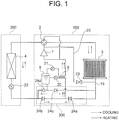
- Fig. 1 is a view showing a configuration of a refrigeration circuit pertaining to a first embodiment of this invention.
- a refrigeration circuit of an air conditioner according to the first embodiment functions as an air conditioner installed in a subject space in order to cool and heat the subject space.
- a refrigerant flows as indicated by dotted line arrows in Fig. 1
- the refrigerant flows as indicated by solid line arrows.
- the refrigeration circuit includes an outdoor unit 100 and an indoor unit 200.
- the outdoor unit 100 is provided with a compressor 1, a four-way valve 2, an outdoor heat exchanger 3, a gas-liquid separator 5, an internal heat exchanger 6, a first decompression valve 20, a second decompression valve 21, an on-off valve 23, and a check valve unit 300.
- the second decompression valve 21 is provided in a pipe that connects a gas side of the gas-liquid separator 5 to an intake section of the compressor 1.
- the on-off valve 23 is provided in a pipe that connects an outlet of the compressor 1 to a liquid side of the outdoor heat exchanger 3.
- the check valve unit 300 is constituted by check valves 24a to 24d. As long as the check valve unit 300 has a function for rectifying the refrigerant flow, the configuration thereof is not limited to a plurality of check valves, and the check valve unit 300 may be constituted by other means such as a four-way valve or a plurality of solenoid valves.
- the indoor unit 200 is constituted by an indoor heat exchanger 4 and a third decompression valve 22.
- the interior of the four-way valve 2 is connected as indicated by solid lines such that the refrigerant flows through the refrigeration circuit as indicated by the dotted line arrows. Further, the first decompression valve 20, the second decompression valve 21, and the third decompression valve 22 are respectively set at appropriate openings, while the on-off valve 23 is fully closed.
- the opening of the third decompression valve 22 is larger than the opening of the first decompression valve 20 such that decompression is realized mainly by the first decompression means 20.
- high-temperature, high-pressure refrigerant gas discharged from the compressor 1 is condensed by the outdoor heat exchanger 3 (a condenser), passes through the check valve 24a so as to be cooled by the internal heat exchanger 6, is decompressed to a certain extent in the first decompression valve 20, and then enters the gas-liquid separator 5.
- Gas refrigerant separated by the gas-liquid separator 5 returns to the intake section of the compressor 1 via the second decompression valve 21, while liquid refrigerant from the gas-liquid separator 5 passes through the check valve 24d and the third decompression valve 22 so as to enter the indoor heat exchanger 4.
- Refrigerant evaporated by the indoor heat exchanger (an evaporator) 4 cools the air in a room, not shown in the drawing, and then self-evaporates so as to return to the intake section of the compressor 1 through the four-way valve 2.
- the refrigerant even in the form of a two-phase refrigerant passing through the second decompression valve 21 can be evaporated by the internal heat exchanger 6 and returned to the intake section of the compressor 1.
- reductions in performance and reliability occurring when liquid returns to the compressor 1 can be suppressed.
- the refrigerant gas is bypassed using the gas-liquid separator 5, and therefore pressure loss in the indoor heat exchanger 4 can be reduced, leading to an increase in intake pressure in the compressor 1 and a corresponding improvement in performance.
- the interior of the four-way valve 2 is connected as indicated by dotted lines such that the refrigerant flows through the refrigeration circuit as indicated by the solid line arrows. Further, the first decompression valve 20, the second decompression valve 21, and the third decompression valve 22 are respectively set at appropriate openings, while the on-off valve 23 is fully closed.
- the opening of the third decompression valve 22 is larger than the opening of the first decompression valve 20 such that decompression is realized mainly by the first decompression valve 20.
- the high-temperature, high-pressure refrigerant gas discharged from the compressor 1 is condensed by the indoor heat exchanger (a condenser) 4, passes through the check valve 24b so as to be cooled by the internal heat exchanger 6, is decompressed to a certain extent in the first decompression valve 20, and then enters the gas-liquid separator 5.
- the gas refrigerant separated by the gas-liquid separator 5 returns to the intake section of the compressor 1 via the second decompression valve 21, while the liquid refrigerant passes through the check valve 24c so as to enter the outdoor heat exchanger (an evaporator) 3.
- Refrigerant evaporated by the outdoor heat exchanger 3 returns to the intake section of the compressor 1 through the four-way valve 2.
- the refrigeration circuit is provided with a bypass pipe 25 that connects the discharge side of the compressor 1 to a lower section of the outdoor heat exchanger 3 (in other words, connects the discharge side of the compressor 1 to a liquid-side collecting pipe 15, to be described below, of the outdoor heat exchanger 3).
- the on-off valve 23, which is provided in the bypass pipe 25, is opened so that high-temperature discharged gas is supplied directly to the liquid pipe side of the outdoor heat exchanger 3. Note that during cooling and heating, the on-off valve 23 is closed.
- the refrigerant discharged from the compressor 1 is supplied from the liquid pipe side to the outdoor heat exchanger 3 through the on-off valve 23.
- the refrigerant having been condensed by the outdoor heat exchanger 3, melts ice caused by frost formed on fins, not shown in the drawing, and is then taken into the compressor 1 through the four-way valve 2.
- the discharged gas is supplied from the lower section of the outdoor heat exchanger 3, where a large amount of frost is formed, and therefore the frost can be melted efficiently.
- a phenomenon whereby ice in the lower section of the outdoor heat exchanger 3 is not completely melted and continues to grow can be avoided.
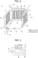
- Fig. 2 is a view showing in detail the configuration of the outdoor heat exchanger 3 of the refrigeration circuit shown in Fig. 1 .
- the outdoor heat exchanger 3 has a parallel-flow type configuration such that when the outdoor heat exchanger 3 operates as a condenser during cooling, the refrigerant forms a parallel flow that flows through the outdoor heat exchanger 3 from top to bottom, as indicated by dotted line arrows, and when the outdoor heat exchanger 3 operates as an evaporator during heating, the refrigerant forms a parallel flow that flows through the outdoor heat exchanger 3 from bottom to top, as indicated by solid line arrows.
- the outdoor heat exchanger 3 includes a plurality of heat exchange sections 3a, 3b, 3c, Fig.
- Each heat exchange section is an imaginary planar unit that extends in an arrangement direction of a plurality of flat tubes, and has a front and a rear serving respectively as an inflow side and an outflow side for air that is subjected to heat exchange.
- a gas-side header pipe 31, a liquid-side header pipe 32, and a plurality of heat exchange pipes 33 provided between the upper-lower pair of header pipes 31, 32 are provided in each heat exchange section 3a, 3b, 3c.
- flat tubes are used as the heat exchange pipes 33.
- Fins 34 are provided between the heat exchange pipes 33.
- One end of a corresponding gas-side connecting pipe 11 is connected to each of the gas-side header pipes 31.
- the other end side of each of the plurality of gas-side connecting pipes 11 is connected to a gas-side collecting pipe 12.
- One end of a corresponding liquid-side connecting pipe 13 is connected to each of the liquid-side header pipes 32.
- a flow control section 14 is provided in at least one of the plurality of liquid-side connecting pipes 13.
- the other end side of each of the plurality of liquid-side connecting pipes 13 is connected to a liquid-side collecting pipe 15 via a branch section 40, to be described below.
- the plurality of heat exchange sections are disposed so as to be connected to one another in parallel between the gas-side collecting pipe 12 and the liquid-side collecting pipe 15.
- blocking members such as metal plates are provided to cover adjacent pairs of heat exchange sections 3 so that the liquid to be subjected to heat exchange does not bypass the heat exchange sections 3.
- the branch section 40 is used to supply refrigerant having an equal degree of dryness to the plurality of liquid-side header pipes 32.
- gas-liquid two phase refrigerant is supplied to the three heat exchange sections at an equal degree of dryness, and the flow rate at which the refrigerant flows to each heat exchange section is controlled by the flow control section 14.
- a distributor may be cited as an example of the branch section 40 with which an equal degree of dryness is obtained.
- a distributor is a flow divider in which inflowing gas-liquid two phase refrigerant is formed into a mist flow in an orifice (a narrow flow passage) and then distributed to a plurality of flow passages.
- One end side of the branch section 40 is connected to the liquid-side collecting pipe 15, and each of a plurality of connection ports at the other end side is connected to one end of the corresponding liquid-side connecting pipe 13.
- the flow control section 14 has a flow control function, and in the example shown in the drawings, employs a capillary tube.
- the flow control section 14 is provided between the branch section 40 and the corresponding liquid-side header pipe 32, or in other words in each liquid-side connecting pipe 13, but does not necessarily have to be provided in all of the liquid-side connecting pipes 13.
- two flow control sections 14 are provided, the flow control sections 14 being provided in two of the three liquid-side connecting pipes 13.
- each liquid-side connecting pipe 13 is connected to the corresponding liquid-side header pipe 32.
- the branch section 40 and the at least one flow control section 14 connected in this manner control the flow rate at which the refrigerant flows to each heat exchange section in accordance with a thermal load of each heat exchange section such that the refrigerant is supplied to the plurality of liquid-side connecting pipes 32 at an equal degree of dryness.
- a connection port between the liquid-side header pipe 32 and the liquid-side connecting pipe 13 and a connection port between the gas-side header pipe 31 and the gas-side connecting pipe 11 are positioned in opposite directions in a lengthwise direction of the header pipes.
- the connection port connecting the liquid-side header pipe 32 to the liquid-side connecting pipe 13 is provided on one end side of the liquid-side header pipe 32
- the connection port connecting the gas-side header pipe 31 to the gas-side connecting pipe 11 is provided on the other end side of the gas-side header pipe 32.
- a refrigerant inlet and a refrigerant outlet to and from the heat exchange section are disposed on opposite sides both vertically and horizontally (opposite sides in the lengthwise direction of the header pipes) such that all of the heat exchange pipes 33 of each heat exchange section have substantially equal refrigerant flow passage lengths.
- Fig. 3 is a perspective view showing the liquid-side header pipe 32 in order to illustrate a perforated pipe. Respective lower ends of the corresponding plurality of heat exchange pipes 33 are connected to an upper section of the liquid-side header pipe 32. As shown in Fig. 3 , a perforated pipe 41 is provided inside each liquid-side header pipe 32.
- the perforated pipe 41 is a block-shaped or pipe-shaped member provided substantially centrally in a space inside the liquid-side header pipe 32 so as not to contact an inner surface of the liquid-side header pipe 32.
- a first space is formed inside the perforated pipe 41, and a second space is formed between an outer side of the perforated pipe 41 and an inner side of the liquid-side header pipe 32.
- a large number of distribution holes 42 are provided in the perforated pipe 41.
- the distribution holes 42 are formed substantially in a lower side of the perforated pipe 41. Hence, when refrigerant gas inside the perforated pipe 41 is ejected through the distribution holes 42, the refrigerant gas is blown into liquid refrigerant that has already accumulated below the perforated pipe 41, thereby promoting gas-liquid mixing.
- the liquid-side header pipe 32 By housing the perforated pipe 41 in the interior of the liquid-side header pipe 32, the liquid-side header pipe 32 is provided with a double pipe structure. Therefore, refrigerant flowing through the liquid-side connecting pipe 13 during heating, for example, flows into the perforated pipe 41, then flows out of the perforated pipe 41 through the large number of distribution holes 42 evenly in a depth direction (a left-right direction on the paper surface of Fig. 3 ), and is then dispersed evenly through the liquid-side header pipe 32 so as to be supplied evenly to the plurality of heat exchange pipes 33 through upper surface holes in the liquid-side header pipe 32.
- the refrigerant gas is bypassed using the gas-liquid separator, and therefore pressure loss in the evaporator can be reduced, leading to an increase in the intake pressure of the compressor and a corresponding improvement in performance during the cooling cycle.
- the indoor heat exchanger with the efficiency of the gas-liquid separator being reduced, the refrigerant even in the form of a two-phase refrigerant passing through the second decompression valve can be evaporated by the indoor heat exchanger and returned to the intake section of the compressor. As a result, reductions in performance and reliability occurring when liquid returns to the compressor can be suppressed.
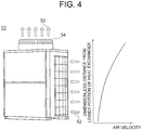
- FIG. 4 is a view showing an outer appearance of an outdoor unit of a multi air conditioner for a building according to the first embodiment.
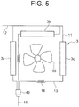
- Fig. 5 is a view showing a connection configuration between a flow divider and a heat exchanger in the outdoor unit of the multi air conditioner for a building according to the first embodiment.
- a top-flow type outdoor unit 51 is a top-flow (upward blowout) type outdoor unit of a (VRF: Variable Refrigerant Flow) multi air conditioner for a building.
- VRF Variable Refrigerant Flow
- Intake air 52 is taken into a casing of the top-flow type outdoor unit 51 from three side faces of the casing and subjected to heat exchange in respective heat exchange sections to be described below, whereupon blowout air 53 is blown out through a blowout port formed in a fan guard 54 provided on an upper surface of the casing.
- the heat exchange sections 3a, 3b, 3c are allocated respectively to three surfaces of the casing of the top-flow type outdoor unit 51, and a propeller fan 55 is disposed centrally in each heat exchange section when seen from above.
- the outdoor unit heat exchanger 3 of the top-flow type outdoor unit 51 operates as an evaporator, and the refrigerant divided into three flows by the branch section 40 flows into the liquid-side header pipe 32 of the corresponding heat exchange section after the flow rate thereof in the corresponding flow passage has been controlled by the flow control section 14.
- the reason for controlling the flow rate of the refrigerant flowing to each heat exchange section in this manner is to regulate differences in thermal load distribution, or in other words temperature distribution and air velocity distribution, among the respective heat exchange sections by means of the flow rate of the refrigerant so that the refrigerant is discharged from the respective heat exchange sections in a uniform condition.
- the refrigerant flowing in through one end of the liquid-side header pipe 32 is then ejected through the distribution holes 42 in the perforated pipe 41 so as to be distributed evenly to the respective heat exchange pipes 33.
- the degree of dryness in the perforated pipe 41 is large, minute liquid droplets are ejected through the small holes, and when the degree of dryness is small, air bubbles shoot up into the liquid that has accumulated in the annular section. As a result, an even distribution is realized regardless of the degree of dryness and the flow rate.
- the refrigerant exchanges heat with air, not shown in the drawings, while passing through the heat exchange pipes 33, then flows into the gas-side header pipe 31, flows out of the other end on the opposite side to the liquid-side header pipe 32, passes through the gas-side connecting pipe 11, and converges with the refrigerant from an adjacent heat exchange section in the gas-side collecting pipe 12.
- the outdoor heat exchanger 3 operates as a condenser, and the refrigerant flows in an opposite direction.
- a plate fin type heat exchanger is used in the top-flow type outdoor unit, a complicated structure in which a number of disposed heat transfer tubes is reduced in order to reduce a heat transfer area so that a uniform heat exchange performance is obtained in the height direction is conventionally employed in a part where the air velocity is high.
- the direction in which an air velocity difference occurs i.e. the height direction
- the magnitude of the unevenness occurring in a single heat exchange section is reduced in the first embodiment by increasing the number of heat exchange sections, and by additionally controlling the flow rate of the refrigerant among the heat exchange sections, a desired heat exchange performance can be obtained.
- the refrigerant is distributed to the heat exchange sections after the dryness of the refrigerant and the flow rate of the refrigerant have been controlled to desired levels in accordance with the conditions of the respective heat exchange sections via the distributor and the flow control section, and therefore an extremely favorable heat exchange performance can be obtained in all of the heat exchange sections.
- a flow passage for collecting the refrigerant that has undergone heat exchange in the plurality of heat exchange pipes and redistributing the refrigerant to the plurality of heat exchange pipes through an inter-row connection section is not provided in the flow direction of the heat exchanger, and therefore a situation in which the refrigerant can no longer be supplied evenly to the plurality of heat exchange pipes does not arise.
- the inlet and outlet to and from the liquid-side header pipe are disposed on opposite sides to the inlet and outlet to and from the gas-side header pipe, and therefore pressure loss in the refrigerant can be made substantially equal in all of the heat exchange pipes. In other words, an evenly distributed gas-liquid two phase flow can be realized.
- minute liquid droplets and air bubbles are ejected through the distribution holes into the annular section of the double structure, thereby promoting even distribution of the gas-liquid two phase refrigerant.
- the number of heat exchange pipes to which the refrigerant is distributed is increased and the number of times the refrigerant is distributed to the heat exchange pipes is reduced (in the example described above, the refrigerant is distributed to the heat exchange pipes only once), and therefore, even though a large number of heat exchange pipes is used, pressure loss in the refrigerant can be suppressed to a low level in proportion to the number of heat exchange pipes.
- this embodiment can be used particularly effectively with a refrigerant exhibiting large refrigerant pressure loss, for example HFO1234yf, HFO1234ze, a mixture thereof, or R134a.
- bypass pipe is provided to connect the discharge side of the compressor to the liquid-side collecting pipe of the outdoor heat exchanger, and therefore the discharged gas can be supplied to the plurality of heat exchange sections at once from the lower section of the outdoor heat exchanger, where a large amount of frost forms. As a result, the frost can be melted efficiently. Moreover, a phenomenon whereby ice in the lower section of the outdoor heat exchanger is not completely melted and continues to grow can be avoided.
- refrigerant in a top-flow type outdoor unit in which an air velocity difference occurs in the height direction, refrigerant can be distributed evenly through a plurality of heat exchange sections without the need for complicated design work relating to a number of branches and a branch pattern. Furthermore, the plurality of heat exchange sections can be defrosted efficiently.
- Fig. 6 is a view showing a connection configuration between a flow divider and a heat exchanger of an outdoor unit of a multi air conditioner for a building according to the second embodiment.
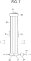
- Fig. 7 is a view pertaining to the second embodiment, and showing configurations of a first row (a front row) and a second row (a back row) of a two-row heat exchanger.
- Fig. 8 is a view pertaining to the second embodiment, and showing an internal configuration of an upper section header of the two-row heat exchanger. Note that except for parts and limitations described below, the second embodiment is assumed to be identical to the first embodiment.
- the heat exchange sections 3a, 3b, 3c are allocated respectively to three intake side faces of a casing.
- the plurality of heat exchange pipes 33 are divided into two groups in a lateral direction (a horizontal direction that is orthogonal to an intake direction of the corresponding heat exchange section), and the respective groups are further divided into two rows in a front-back direction (the intake direction of the corresponding heat exchange section).
- the heat exchange section 3a is divided into two groups 3h, 3i, and the respective groups 3h, 3i are further divided into two rows in the front-back direction.
- the heat exchange section 3b is divided into two groups 3f, 3g and the respective groups 3f, 3g are further divided into two rows in the front-back direction
- the heat exchange section 3c is divided into two groups 3e, 3d and the respective groups 3e, 3d are further divided into two rows in the front-back direction.
- the plurality of heat exchange pipes 33 are divided into twelve rows in terms of the row units described above.
- arrows R in Fig. 7 show movement of the refrigerant, in which the refrigerant that rises through the heat exchange pipes 33 of the first row and the refrigerant that falls through the heat exchange pipes 33 of the second row form opposing flows.
- An upper end of the plurality of heat exchange pipes 33 forming the first row (a front row) and an upper end of the plurality of heat exchange pipes forming the second row (a back row) are connected by the inter-row connection section 35.
- the refrigerant is joined in a row direction but partitioned by partition walls 36 in the lateral direction (the arrangement direction of the heat exchange pipes 33 forming each group, or in other words a horizontal direction that is orthogonal to the intake direction of the corresponding group) so that refrigerant in adjacent heat exchange pipes in the lateral direction does not intermix.
- the refrigerant flowing into the gas-side header pipe 31 flows into a liquid-side convergence pipe 37, and in the liquid-side convergence pipe 37 converges with refrigerant flowing into the liquid-side convergence pipe 37 from the gas-side header pipe 31 of an adjacent group in the lateral direction.
- the refrigerant is supplied to the respective heat exchange sections via the branch section 40, a T branch section 43, and the flow control section 14. Having undergone heat exchange in the respective heat exchange sections, the refrigerant from adjacent groups converges in the liquid-side convergence pipe 37 and flows out of the outdoor heat exchanger 3 through the gas-side connecting pipe 11 and an upper section convergence pipe 12.
- the outdoor unit heat exchanger 3 operates as an evaporator, and each of the three flows of refrigerant divided by the branch section 40 is divided into a further two flows by the T branch section 43 so as to form six flows.
- the flow rate of each flow of refrigerant in the corresponding flow passage is then controlled by the flow control section 14, whereupon the refrigerant flows into the liquid-side header pipe 32 of the corresponding heat exchange section.
- the reason for controlling the flow rate of the refrigerant flowing to each heat exchange section in this manner is to regulate differences in thermal load distribution, or in other words temperature distribution and air velocity distribution, among the respective heat exchange sections by means of the flow rate of the refrigerant so that the refrigerant is discharged from the respective heat exchange sections in a uniform condition.
- thermal load distribution or in other words temperature distribution and air velocity distribution
- the refrigerant is distributed unevenly through the respective heat exchange sections.
- this phenomenon is dealt with by providing the six groups.
- the number of groups into which the heat exchange pipes are divided does not have to be limited to six, and may be set at seven or more.
- the refrigerant flowing in from one end of the liquid-side header pipe 32 is ejected through the distribution holes 42 in the perforated pipe 41 so as to be distributed evenly to the respective heat exchange pipes 33.
- the degree of dryness in the perforated pipe 41 is large, minute liquid droplets are ejected through the small holes, and when the degree of dryness is small, air bubbles shoot up into the liquid that has accumulated in the annular section. As a result, an even distribution is realized regardless of the degree of dryness and the flow rate.
- the refrigerant exchanges heat with air, not shown in the drawings, while passing through the heat exchange pipes 33, then flows into the gas-side header pipe 31, flows out of the other end on the opposite side to the liquid-side header pipe 32, and converges with the refrigerant from the adjacent group in the liquid-side convergence pipe 37.
- partitions are provided in the lateral direction so that heat is not exchanged directly with an adjacent heat transfer tube in the lateral direction.
- the refrigerant flows out through the liquid-side convergence pipe 37, passes through the corresponding gas-side connecting pipe 11, and converges in the gas-side collecting pipe 12.
- the large number of distribution holes are oriented downward, but the manner in which the distribution holes are formed is not limited thereto, and the orientation, number, and hole shape of the distribution holes may be amended as appropriate.
- the configuration of the branch section described above is merely an example, and may be amended as appropriate.
- a branch section such as a Y-shaped branch pipe or a low pressure loss distributor, in which the height positions of a plurality of outlet side branch passages are varied, whereby the proportion of the divided flow of the liquid phase is varied using the effects of gravity so that the degree of dryness and the flow rate can be controlled simultaneously, may be used instead.
Landscapes
- Engineering & Computer Science (AREA)
- Mechanical Engineering (AREA)
- General Engineering & Computer Science (AREA)
- Physics & Mathematics (AREA)
- Thermal Sciences (AREA)
- Chemical & Material Sciences (AREA)
- Combustion & Propulsion (AREA)
- Analytical Chemistry (AREA)
- Power Engineering (AREA)
- Other Air-Conditioning Systems (AREA)
- Heat-Exchange Devices With Radiators And Conduit Assemblies (AREA)
- Compression-Type Refrigeration Machines With Reversible Cycles (AREA)
Applications Claiming Priority (1)
| Application Number | Priority Date | Filing Date | Title |
|---|---|---|---|
| PCT/JP2014/061285 WO2015162689A1 (fr) | 2014-04-22 | 2014-04-22 | Conditionneur d'air |
Publications (2)
| Publication Number | Publication Date |
|---|---|
| EP3141825A1 true EP3141825A1 (fr) | 2017-03-15 |
| EP3141825A4 EP3141825A4 (fr) | 2018-01-03 |
Family
ID=54331883
Family Applications (1)
| Application Number | Title | Priority Date | Filing Date |
|---|---|---|---|
| EP14889898.4A Withdrawn EP3141825A4 (fr) | 2014-04-22 | 2014-04-22 | Conditionneur d'air |
Country Status (7)
| Country | Link |
|---|---|
| US (1) | US10393408B2 (fr) |
| EP (1) | EP3141825A4 (fr) |
| JP (1) | JP6352401B2 (fr) |
| KR (1) | KR20160146885A (fr) |
| CN (1) | CN106233077B (fr) |
| AU (1) | AU2014391505B2 (fr) |
| WO (1) | WO2015162689A1 (fr) |
Cited By (2)
| Publication number | Priority date | Publication date | Assignee | Title |
|---|---|---|---|---|
| EP3663679A4 (fr) * | 2017-08-03 | 2020-08-12 | Mitsubishi Electric Corporation | Échangeur de chaleur et dispositif à cycle frigorifique |
| EP3760949A4 (fr) * | 2018-03-02 | 2021-01-20 | Panasonic Intellectual Property Management Co., Ltd. | Unité d'échangeur de chaleur et climatiseur l'utilisant |
Families Citing this family (35)
| Publication number | Priority date | Publication date | Assignee | Title |
|---|---|---|---|---|
| EP3015793B1 (fr) * | 2014-10-29 | 2018-01-10 | LG Electronics Inc. | Climatisation et procédé de commande correspondant |
| CN108139106B (zh) * | 2015-10-26 | 2020-10-30 | 三菱电机株式会社 | 空气调节装置 |
| WO2017221401A1 (fr) * | 2016-06-24 | 2017-12-28 | 三菱電機株式会社 | Distributeur de dérivation de réfrigérant, échangeur de chaleur le comprenant et dispositif à cycle de réfrigération |
| EP3492844B1 (fr) * | 2016-08-01 | 2020-03-11 | Mitsubishi Electric Corporation | Climatiseur |
| CN106763909B (zh) * | 2017-01-21 | 2023-04-18 | 佛山市德天电器有限公司 | 三孔单向阀及具有三孔单向阀的无霜热泵系统 |
| CN108332285B (zh) * | 2017-12-29 | 2019-12-06 | 青岛海尔空调器有限总公司 | 空调器系统 |
| KR102674404B1 (ko) * | 2018-04-20 | 2024-06-13 | 엘지전자 주식회사 | 저온 저장고의 냉각 시스템 |
| US11333369B2 (en) * | 2018-06-11 | 2022-05-17 | Mitsubishi Electric Corporation | Refrigerant distributor, heat exchanger, and air-conditioning apparatus |
| CN112204312B (zh) * | 2018-06-11 | 2022-06-28 | 三菱电机株式会社 | 空气调节装置的室外机及空气调节装置 |
| JP6925393B2 (ja) * | 2018-06-11 | 2021-08-25 | 三菱電機株式会社 | 空気調和装置の室外機及び空気調和装置 |
| CN109631419A (zh) * | 2018-12-20 | 2019-04-16 | 广州美的华凌冰箱有限公司 | 热交换装置和冰箱 |
| CN113330268B (zh) * | 2019-02-04 | 2023-05-16 | 三菱电机株式会社 | 热交换器以及具备热交换器的空气调节装置 |
| WO2020255187A1 (fr) * | 2019-06-17 | 2020-12-24 | 三菱電機株式会社 | Appareil de conditionnement d'air |
| CN112696839B (zh) * | 2019-10-18 | 2022-12-27 | 广东美的制冷设备有限公司 | 空调系统、空调器及其控制方法、控制装置 |
| US11262112B2 (en) | 2019-12-02 | 2022-03-01 | Johnson Controls Technology Company | Condenser coil arrangement |
| JP7366255B2 (ja) * | 2020-05-22 | 2023-10-20 | 三菱電機株式会社 | 熱交換器、空気調和装置の室外機及び空気調和装置 |
| EP4155646B1 (fr) * | 2020-05-22 | 2025-10-08 | Mitsubishi Electric Corporation | Échangeur de chaleur, unité extérieure et dispositif à cycle de réfrigération |
| CN111854245B (zh) * | 2020-06-28 | 2021-06-01 | 珠海格力电器股份有限公司 | 具有化霜功能的热泵机组及其控制方法 |
| EP4015938B1 (fr) * | 2020-12-18 | 2025-11-26 | Carrier Corporation | Refroidisseur refroidi par air avec récupération de la chaleur |
| WO2022215242A1 (fr) * | 2021-04-09 | 2022-10-13 | 三菱電機株式会社 | Unité extérieure et dispositif de climatisation |
| CN113091355B (zh) * | 2021-04-16 | 2021-11-19 | 东北大学 | 一种分液均匀的热管与蒸气压缩复合空调系统及方法 |
| CN115218362A (zh) * | 2021-04-21 | 2022-10-21 | 芜湖美智空调设备有限公司 | 空调器的补气控制方法、装置、空调器及存储介质 |
| CN113175735B (zh) * | 2021-04-21 | 2022-07-19 | 海信空调有限公司 | 计算空调器能力能效的方法、计算机存储介质和空调器 |
| WO2023012899A1 (fr) * | 2021-08-03 | 2023-02-09 | 三菱電機株式会社 | Dispositif à cycle frigorifique |
| JP7239857B1 (ja) * | 2021-09-30 | 2023-03-15 | ダイキン工業株式会社 | 空気調和機 |
| JP7682374B2 (ja) * | 2022-03-07 | 2025-05-23 | 三菱電機株式会社 | 冷凍サイクル装置 |
| JP7693095B2 (ja) * | 2022-03-18 | 2025-06-16 | 三菱電機株式会社 | 空気調和装置の室外機および空気調和装置 |
| CN118946764A (zh) * | 2022-04-01 | 2024-11-12 | 三菱电机株式会社 | 室外机以及具备室外机的空调装置 |
| DE102022113409A1 (de) * | 2022-05-27 | 2023-11-30 | Güntner Gmbh & Co. Kg | Vorrichtung mit einem Wärmeübertrager und Verfahren zum Betreiben eines Wärmeübertragers einer Vorrichtung |
| WO2023233572A1 (fr) * | 2022-06-01 | 2023-12-07 | 三菱電機株式会社 | Échangeur de chaleur et dispositif à cycle de réfrigération |
| CN114992899B (zh) * | 2022-06-10 | 2023-06-16 | 海信空调有限公司 | 一种空调器及其防油堵控制方法 |
| JPWO2025150184A1 (fr) * | 2024-01-12 | 2025-07-17 | ||
| WO2025154256A1 (fr) * | 2024-01-19 | 2025-07-24 | 三菱電機株式会社 | Échangeur de chaleur et dispositif à cycle de réfrigération |
| WO2025158523A1 (fr) * | 2024-01-23 | 2025-07-31 | 三菱電機株式会社 | Échangeur de chaleur, unité extérieure et dispositif à cycle de réfrigération |
| WO2025181955A1 (fr) * | 2024-02-28 | 2025-09-04 | 三菱電機株式会社 | Unité extérieure pour dispositif de climatisation et dispositif de climatisation |
Family Cites Families (25)
| Publication number | Priority date | Publication date | Assignee | Title |
|---|---|---|---|---|
| JPH0440114Y2 (fr) * | 1987-06-11 | 1992-09-21 | ||
| JPH0545007A (ja) * | 1991-08-09 | 1993-02-23 | Nippondenso Co Ltd | 冷凍サイクル |
| JP2971223B2 (ja) | 1991-11-29 | 1999-11-02 | 三菱重工業株式会社 | 空気調和機 |
| JP2002071208A (ja) * | 2000-08-30 | 2002-03-08 | Hitachi Ltd | 熱交換器及び空気調和機用室内機並びに室外機 |
| EP1654511A4 (fr) * | 2003-08-01 | 2012-05-30 | Showa Denko Kk | Echangeur thermique |
| EP1548380A3 (fr) | 2003-12-22 | 2006-10-04 | Hussmann Corporation | Evaporateur à tubes plats avec micro-distributeur |
| JP4613645B2 (ja) * | 2005-03-09 | 2011-01-19 | 株式会社デンソー | 熱交換器 |
| KR20080022324A (ko) | 2006-09-06 | 2008-03-11 | 한라공조주식회사 | 2열 열교환기 |
| JP2008096095A (ja) | 2006-09-13 | 2008-04-24 | Daikin Ind Ltd | 冷凍装置 |
| CN101516775B (zh) * | 2006-09-18 | 2011-12-28 | 国际壳牌研究有限公司 | 用于制备二硫化碳的方法 |
| JP4370535B2 (ja) * | 2007-06-28 | 2009-11-25 | ソニー株式会社 | 画像表示装置、撮像装置、画像表示制御方法、プログラム |
| WO2009018150A1 (fr) * | 2007-07-27 | 2009-02-05 | Johnson Controls Technology Company | Echangeur thermique a multiples canaux |
| EP2275757B1 (fr) * | 2008-03-31 | 2018-02-28 | Mitsubishi Electric Corporation | Système complexe de climatisation et de fourniture d'eau chaude |
| GB0807398D0 (en) * | 2008-04-23 | 2008-05-28 | Airbus Uk Ltd | Improved method of tape laying of thermoplastic composite materials |
| WO2009134760A2 (fr) * | 2008-04-29 | 2009-11-05 | Carrier Corporation | Échangeur de chaleur modulaire |
| JPWO2010082325A1 (ja) | 2009-01-15 | 2012-06-28 | 三菱電機株式会社 | 空気調和装置 |
| US9433459B2 (en) * | 2010-07-13 | 2016-09-06 | Zoll Medical Corporation | Deposit ablation within and external to circulatory systems |
| JP5602243B2 (ja) * | 2010-11-19 | 2014-10-08 | 三菱電機株式会社 | 空気調和機 |
| CN103443556B (zh) | 2011-03-28 | 2016-06-15 | 三菱电机株式会社 | 空气调节装置 |
| FR2977304B1 (fr) * | 2011-06-28 | 2013-07-19 | Valeo Systemes Thermiques | Echangeur de chaleur, boitier et circuit de climatisation comprenant un tel echangeur |
| JP5360186B2 (ja) * | 2011-11-30 | 2013-12-04 | ダイキン工業株式会社 | 空気調和装置の室外機 |
| JP5518104B2 (ja) | 2012-01-06 | 2014-06-11 | 三菱電機株式会社 | 熱交換器、室内機、および室外機 |
| ES2702291T3 (es) | 2012-04-26 | 2019-02-28 | Mitsubishi Electric Corp | Intercambiador de calor y método de intercambio de calor |
| US9335076B2 (en) | 2012-09-04 | 2016-05-10 | Allied Air Enterprises Llc | Distributor assembly for space conditioning systems |
| BR112015006703A2 (pt) * | 2012-09-28 | 2017-07-04 | Electrolux Home Products Corp Nv | refrigerador |
-
2014
- 2014-04-22 KR KR1020167032399A patent/KR20160146885A/ko not_active Ceased
- 2014-04-22 EP EP14889898.4A patent/EP3141825A4/fr not_active Withdrawn
- 2014-04-22 JP JP2016514580A patent/JP6352401B2/ja active Active
- 2014-04-22 AU AU2014391505A patent/AU2014391505B2/en not_active Ceased
- 2014-04-22 US US15/305,152 patent/US10393408B2/en active Active
- 2014-04-22 CN CN201480077991.1A patent/CN106233077B/zh active Active
- 2014-04-22 WO PCT/JP2014/061285 patent/WO2015162689A1/fr not_active Ceased
Cited By (2)
| Publication number | Priority date | Publication date | Assignee | Title |
|---|---|---|---|---|
| EP3663679A4 (fr) * | 2017-08-03 | 2020-08-12 | Mitsubishi Electric Corporation | Échangeur de chaleur et dispositif à cycle frigorifique |
| EP3760949A4 (fr) * | 2018-03-02 | 2021-01-20 | Panasonic Intellectual Property Management Co., Ltd. | Unité d'échangeur de chaleur et climatiseur l'utilisant |
Also Published As
| Publication number | Publication date |
|---|---|
| KR20160146885A (ko) | 2016-12-21 |
| CN106233077A (zh) | 2016-12-14 |
| EP3141825A4 (fr) | 2018-01-03 |
| AU2014391505A1 (en) | 2016-11-10 |
| JP6352401B2 (ja) | 2018-07-04 |
| AU2014391505B2 (en) | 2018-11-22 |
| JPWO2015162689A1 (ja) | 2017-04-13 |
| US20170122630A1 (en) | 2017-05-04 |
| US10393408B2 (en) | 2019-08-27 |
| WO2015162689A1 (fr) | 2015-10-29 |
| CN106233077B (zh) | 2019-08-09 |
Similar Documents
| Publication | Publication Date | Title |
|---|---|---|
| US10393408B2 (en) | Air conditioner | |
| US9518788B2 (en) | Heat exchanger | |
| US20160327343A1 (en) | Heat exchanger of air conditioner | |
| US20170292741A1 (en) | Heat exchanger and air conditioning apparatus | |
| US20130220584A1 (en) | Heat exchanger, and all-in-one air conditioner equipped therewith | |
| EP3156752B1 (fr) | Échangeur thermique | |
| JP6827542B2 (ja) | 冷凍サイクル装置 | |
| US20200200477A1 (en) | Heat exchanger and heat exchange unit including the same | |
| US20200200476A1 (en) | Heat exchanger | |
| KR102148722B1 (ko) | 열교환기 및 이를 갖는 공기조화기 | |
| US11692748B2 (en) | Heat exchanger and air conditioning apparatus including the same | |
| JP6590957B2 (ja) | 冷凍装置 | |
| JP2020115070A (ja) | 熱交換器 | |
| JP2020085268A (ja) | 熱交換器 | |
| CN111750573B (zh) | 热交换器分流器 | |
| JP2019060513A (ja) | 熱交換器及びそれを備えた空気調和装置 | |
| JP2018048769A (ja) | 熱交換器 | |
| JP6817996B2 (ja) | 熱交換器用のヘッダ、熱交換器、室外機及び空気調和機 | |
| CN111256383B (zh) | 复合换热器以及具有该复合换热器的换热系统 | |
| TW201738524A (zh) | 熱交換器及空氣調節機 | |
| WO2023199466A1 (fr) | Échangeur de chaleur et dispositif de climatisation l'incluant | |
| KR100600068B1 (ko) | 열교환기 |
Legal Events
| Date | Code | Title | Description |
|---|---|---|---|
| STAA | Information on the status of an ep patent application or granted ep patent |
Free format text: STATUS: THE INTERNATIONAL PUBLICATION HAS BEEN MADE |
|
| PUAI | Public reference made under article 153(3) epc to a published international application that has entered the european phase |
Free format text: ORIGINAL CODE: 0009012 |
|
| STAA | Information on the status of an ep patent application or granted ep patent |
Free format text: STATUS: REQUEST FOR EXAMINATION WAS MADE |
|
| 17P | Request for examination filed |
Effective date: 20161119 |
|
| AK | Designated contracting states |
Kind code of ref document: A1 Designated state(s): AL AT BE BG CH CY CZ DE DK EE ES FI FR GB GR HR HU IE IS IT LI LT LU LV MC MK MT NL NO PL PT RO RS SE SI SK SM TR |
|
| AX | Request for extension of the european patent |
Extension state: BA ME |
|
| DAX | Request for extension of the european patent (deleted) | ||
| A4 | Supplementary search report drawn up and despatched |
Effective date: 20171205 |
|
| RIC1 | Information provided on ipc code assigned before grant |
Ipc: F25B 13/00 20060101ALI20171129BHEP Ipc: F25B 39/02 20060101ALI20171129BHEP Ipc: F25B 40/00 20060101ALI20171129BHEP Ipc: F24F 11/02 00000000ALI20171129BHEP Ipc: F24F 1/18 20110101AFI20171129BHEP Ipc: F25B 1/00 20060101ALI20171129BHEP Ipc: F25B 41/04 20060101ALI20171129BHEP Ipc: F25B 47/02 20060101ALI20171129BHEP |
|
| RIC1 | Information provided on ipc code assigned before grant |
Ipc: F25B 47/02 20060101ALI20171129BHEP Ipc: F25B 39/02 20060101ALI20171129BHEP Ipc: F24F 11/02 20060101ALI20171129BHEP Ipc: F24F 1/18 20110101AFI20171129BHEP Ipc: F25B 40/00 20060101ALI20171129BHEP Ipc: F25B 1/00 20060101ALI20171129BHEP Ipc: F25B 41/04 20060101ALI20171129BHEP Ipc: F25B 13/00 20060101ALI20171129BHEP |
|
| STAA | Information on the status of an ep patent application or granted ep patent |
Free format text: STATUS: EXAMINATION IS IN PROGRESS |
|
| 17Q | First examination report despatched |
Effective date: 20200512 |
|
| GRAP | Despatch of communication of intention to grant a patent |
Free format text: ORIGINAL CODE: EPIDOSNIGR1 |
|
| STAA | Information on the status of an ep patent application or granted ep patent |
Free format text: STATUS: GRANT OF PATENT IS INTENDED |
|
| RIC1 | Information provided on ipc code assigned before grant |
Ipc: F24F 1/18 20110101AFI20250228BHEP Ipc: F25B 47/02 20060101ALI20250228BHEP Ipc: F25B 1/00 20060101ALI20250228BHEP |
|
| INTG | Intention to grant announced |
Effective date: 20250312 |
|
| STAA | Information on the status of an ep patent application or granted ep patent |
Free format text: STATUS: THE APPLICATION IS DEEMED TO BE WITHDRAWN |
|
| 18D | Application deemed to be withdrawn |
Effective date: 20250715 |