EP3141849A1 - Appareil pour fournir de l'eau fonctionnelle - Google Patents
Appareil pour fournir de l'eau fonctionnelle Download PDFInfo
- Publication number
- EP3141849A1 EP3141849A1 EP14898799.3A EP14898799A EP3141849A1 EP 3141849 A1 EP3141849 A1 EP 3141849A1 EP 14898799 A EP14898799 A EP 14898799A EP 3141849 A1 EP3141849 A1 EP 3141849A1
- Authority
- EP
- European Patent Office
- Prior art keywords
- cold water
- module
- soda
- water
- water supply
- Prior art date
- Legal status (The legal status is an assumption and is not a legal conclusion. Google has not performed a legal analysis and makes no representation as to the accuracy of the status listed.)
- Withdrawn
Links
- XLYOFNOQVPJJNP-UHFFFAOYSA-N water Substances O XLYOFNOQVPJJNP-UHFFFAOYSA-N 0.000 title claims abstract description 1092
- 238000007710 freezing Methods 0.000 claims abstract description 16
- 230000008014 freezing Effects 0.000 claims abstract description 16
- CDBYLPFSWZWCQE-UHFFFAOYSA-L Sodium Carbonate Chemical compound [Na+].[Na+].[O-]C([O-])=O CDBYLPFSWZWCQE-UHFFFAOYSA-L 0.000 claims description 234
- 238000001816 cooling Methods 0.000 claims description 78
- 238000003780 insertion Methods 0.000 claims description 17
- 230000037431 insertion Effects 0.000 claims description 17
- 238000004781 supercooling Methods 0.000 claims description 4
- 238000012546 transfer Methods 0.000 claims description 4
- CURLTUGMZLYLDI-UHFFFAOYSA-N Carbon dioxide Chemical compound O=C=O CURLTUGMZLYLDI-UHFFFAOYSA-N 0.000 description 28
- 235000011089 carbon dioxide Nutrition 0.000 description 28
- 230000035515 penetration Effects 0.000 description 17
- 238000004519 manufacturing process Methods 0.000 description 11
- 238000000034 method Methods 0.000 description 8
- 230000008569 process Effects 0.000 description 8
- 238000003860 storage Methods 0.000 description 8
- 206010060904 Freezing phenomenon Diseases 0.000 description 7
- 239000003507 refrigerant Substances 0.000 description 7
- 239000004606 Fillers/Extenders Substances 0.000 description 6
- 238000005192 partition Methods 0.000 description 6
- 230000002708 enhancing effect Effects 0.000 description 5
- 238000009434 installation Methods 0.000 description 5
- 238000013461 design Methods 0.000 description 4
- 238000010438 heat treatment Methods 0.000 description 4
- 238000012856 packing Methods 0.000 description 4
- 239000008399 tap water Substances 0.000 description 4
- 235000020679 tap water Nutrition 0.000 description 4
- 238000004140 cleaning Methods 0.000 description 3
- 239000000470 constituent Substances 0.000 description 3
- 230000009977 dual effect Effects 0.000 description 3
- 238000005516 engineering process Methods 0.000 description 3
- 230000002093 peripheral effect Effects 0.000 description 3
- 230000008439 repair process Effects 0.000 description 3
- 230000004044 response Effects 0.000 description 3
- XUIMIQQOPSSXEZ-UHFFFAOYSA-N Silicon Chemical compound [Si] XUIMIQQOPSSXEZ-UHFFFAOYSA-N 0.000 description 2
- 238000006243 chemical reaction Methods 0.000 description 2
- 239000000498 cooling water Substances 0.000 description 2
- 230000008878 coupling Effects 0.000 description 2
- 238000010168 coupling process Methods 0.000 description 2
- 238000005859 coupling reaction Methods 0.000 description 2
- 230000003247 decreasing effect Effects 0.000 description 2
- 230000000694 effects Effects 0.000 description 2
- 238000004049 embossing Methods 0.000 description 2
- 239000000463 material Substances 0.000 description 2
- 238000012986 modification Methods 0.000 description 2
- 230000004048 modification Effects 0.000 description 2
- 239000008213 purified water Substances 0.000 description 2
- 229910052710 silicon Inorganic materials 0.000 description 2
- 239000010703 silicon Substances 0.000 description 2
- 239000008400 supply water Substances 0.000 description 2
- 241000894006 Bacteria Species 0.000 description 1
- 230000004075 alteration Effects 0.000 description 1
- 230000000903 blocking effect Effects 0.000 description 1
- 230000006835 compression Effects 0.000 description 1
- 238000007906 compression Methods 0.000 description 1
- 238000011109 contamination Methods 0.000 description 1
- 238000011161 development Methods 0.000 description 1
- 230000035622 drinking Effects 0.000 description 1
- 238000005485 electric heating Methods 0.000 description 1
- 238000001704 evaporation Methods 0.000 description 1
- 230000008020 evaporation Effects 0.000 description 1
- 229910052500 inorganic mineral Inorganic materials 0.000 description 1
- 239000000155 melt Substances 0.000 description 1
- 239000011707 mineral Substances 0.000 description 1
- 230000002265 prevention Effects 0.000 description 1
- 238000007789 sealing Methods 0.000 description 1
- 239000002210 silicon-based material Substances 0.000 description 1
- 238000000638 solvent extraction Methods 0.000 description 1
- 125000006850 spacer group Chemical group 0.000 description 1
- 239000000126 substance Substances 0.000 description 1
Images


Classifications
-
- F—MECHANICAL ENGINEERING; LIGHTING; HEATING; WEAPONS; BLASTING
- F25—REFRIGERATION OR COOLING; COMBINED HEATING AND REFRIGERATION SYSTEMS; HEAT PUMP SYSTEMS; MANUFACTURE OR STORAGE OF ICE; LIQUEFACTION SOLIDIFICATION OF GASES
- F25D—REFRIGERATORS; COLD ROOMS; ICE-BOXES; COOLING OR FREEZING APPARATUS NOT OTHERWISE PROVIDED FOR
- F25D31/00—Other cooling or freezing apparatus
- F25D31/002—Liquid coolers, e.g. beverage cooler
-
- B—PERFORMING OPERATIONS; TRANSPORTING
- B01—PHYSICAL OR CHEMICAL PROCESSES OR APPARATUS IN GENERAL
- B01F—MIXING, e.g. DISSOLVING, EMULSIFYING OR DISPERSING
- B01F23/00—Mixing according to the phases to be mixed, e.g. dispersing or emulsifying
- B01F23/20—Mixing gases with liquids
- B01F23/23—Mixing gases with liquids by introducing gases into liquid media, e.g. for producing aerated liquids
- B01F23/236—Mixing gases with liquids by introducing gases into liquid media, e.g. for producing aerated liquids specially adapted for aerating or carbonating beverages
- B01F23/2362—Mixing gases with liquids by introducing gases into liquid media, e.g. for producing aerated liquids specially adapted for aerating or carbonating beverages for aerating or carbonating within receptacles or tanks, e.g. distribution machines
-
- B—PERFORMING OPERATIONS; TRANSPORTING
- B67—OPENING, CLOSING OR CLEANING BOTTLES, JARS OR SIMILAR CONTAINERS; LIQUID HANDLING
- B67D—DISPENSING, DELIVERING OR TRANSFERRING LIQUIDS, NOT OTHERWISE PROVIDED FOR
- B67D1/00—Apparatus or devices for dispensing beverages on draught
- B67D1/0003—Apparatus or devices for dispensing beverages on draught the beverage being a single liquid
- B67D1/0014—Apparatus or devices for dispensing beverages on draught the beverage being a single liquid the beverage being supplied from water mains
-
- B—PERFORMING OPERATIONS; TRANSPORTING
- B67—OPENING, CLOSING OR CLEANING BOTTLES, JARS OR SIMILAR CONTAINERS; LIQUID HANDLING
- B67D—DISPENSING, DELIVERING OR TRANSFERRING LIQUIDS, NOT OTHERWISE PROVIDED FOR
- B67D1/00—Apparatus or devices for dispensing beverages on draught
- B67D1/0042—Details of specific parts of the dispensers
- B67D1/0057—Carbonators
- B67D1/0061—Carbonators with cooling means
- B67D1/0066—Carbonators with cooling means outside the carbonator
- B67D1/0067—Cooling coil
-
- B—PERFORMING OPERATIONS; TRANSPORTING
- B67—OPENING, CLOSING OR CLEANING BOTTLES, JARS OR SIMILAR CONTAINERS; LIQUID HANDLING
- B67D—DISPENSING, DELIVERING OR TRANSFERRING LIQUIDS, NOT OTHERWISE PROVIDED FOR
- B67D1/00—Apparatus or devices for dispensing beverages on draught
- B67D1/08—Details
- B67D1/0857—Cooling arrangements
- B67D1/0858—Cooling arrangements using compression systems
- B67D1/0861—Cooling arrangements using compression systems the evaporator acting through an intermediate heat transfer means
- B67D1/0864—Cooling arrangements using compression systems the evaporator acting through an intermediate heat transfer means in the form of a cooling bath
-
- B—PERFORMING OPERATIONS; TRANSPORTING
- B67—OPENING, CLOSING OR CLEANING BOTTLES, JARS OR SIMILAR CONTAINERS; LIQUID HANDLING
- B67D—DISPENSING, DELIVERING OR TRANSFERRING LIQUIDS, NOT OTHERWISE PROVIDED FOR
- B67D1/00—Apparatus or devices for dispensing beverages on draught
- B67D1/08—Details
- B67D1/0895—Heating arrangements
-
- B—PERFORMING OPERATIONS; TRANSPORTING
- B67—OPENING, CLOSING OR CLEANING BOTTLES, JARS OR SIMILAR CONTAINERS; LIQUID HANDLING
- B67D—DISPENSING, DELIVERING OR TRANSFERRING LIQUIDS, NOT OTHERWISE PROVIDED FOR
- B67D3/00—Apparatus or devices for controlling flow of liquids under gravity from storage containers for dispensing purposes
- B67D3/0022—Apparatus or devices for controlling flow of liquids under gravity from storage containers for dispensing purposes provided with heating arrangements
-
- B—PERFORMING OPERATIONS; TRANSPORTING
- B67—OPENING, CLOSING OR CLEANING BOTTLES, JARS OR SIMILAR CONTAINERS; LIQUID HANDLING
- B67D—DISPENSING, DELIVERING OR TRANSFERRING LIQUIDS, NOT OTHERWISE PROVIDED FOR
- B67D2210/00—Indexing scheme relating to aspects and details of apparatus or devices for dispensing beverages on draught or for controlling flow of liquids under gravity from storage containers for dispensing purposes
- B67D2210/00028—Constructional details
- B67D2210/00099—Temperature control
- B67D2210/00118—Heating and cooling
-
- F—MECHANICAL ENGINEERING; LIGHTING; HEATING; WEAPONS; BLASTING
- F25—REFRIGERATION OR COOLING; COMBINED HEATING AND REFRIGERATION SYSTEMS; HEAT PUMP SYSTEMS; MANUFACTURE OR STORAGE OF ICE; LIQUEFACTION SOLIDIFICATION OF GASES
- F25D—REFRIGERATORS; COLD ROOMS; ICE-BOXES; COOLING OR FREEZING APPARATUS NOT OTHERWISE PROVIDED FOR
- F25D21/00—Defrosting; Preventing frosting; Removing condensed or defrost water
- F25D21/04—Preventing the formation of frost or condensate
-
- F—MECHANICAL ENGINEERING; LIGHTING; HEATING; WEAPONS; BLASTING
- F25—REFRIGERATION OR COOLING; COMBINED HEATING AND REFRIGERATION SYSTEMS; HEAT PUMP SYSTEMS; MANUFACTURE OR STORAGE OF ICE; LIQUEFACTION SOLIDIFICATION OF GASES
- F25D—REFRIGERATORS; COLD ROOMS; ICE-BOXES; COOLING OR FREEZING APPARATUS NOT OTHERWISE PROVIDED FOR
- F25D2400/00—General features of, or devices for refrigerators, cold rooms, ice-boxes, or for cooling or freezing apparatus not covered by any other subclass
- F25D2400/02—Refrigerators including a heater
-
- F—MECHANICAL ENGINEERING; LIGHTING; HEATING; WEAPONS; BLASTING
- F28—HEAT EXCHANGE IN GENERAL
- F28D—HEAT-EXCHANGE APPARATUS, NOT PROVIDED FOR IN ANOTHER SUBCLASS, IN WHICH THE HEAT-EXCHANGE MEDIA DO NOT COME INTO DIRECT CONTACT
- F28D7/00—Heat-exchange apparatus having stationary tubular conduit assemblies for both heat-exchange media, the media being in contact with different sides of a conduit wall
- F28D7/02—Heat-exchange apparatus having stationary tubular conduit assemblies for both heat-exchange media, the media being in contact with different sides of a conduit wall the conduits being helically coiled
- F28D7/026—Heat-exchange apparatus having stationary tubular conduit assemblies for both heat-exchange media, the media being in contact with different sides of a conduit wall the conduits being helically coiled the conduits of only one medium being helically coiled and formed by bent members, e.g. plates, the coils having a cylindrical configuration
-
- F—MECHANICAL ENGINEERING; LIGHTING; HEATING; WEAPONS; BLASTING
- F28—HEAT EXCHANGE IN GENERAL
- F28F—DETAILS OF HEAT-EXCHANGE AND HEAT-TRANSFER APPARATUS, OF GENERAL APPLICATION
- F28F19/00—Preventing the formation of deposits or corrosion, e.g. by using filters or scrapers
- F28F19/006—Preventing deposits of ice
Definitions
- At least one example embodiment relates to an apparatus for supplying functional water, and more particularly, to an apparatus for supplying functional water that may provide soda water in addition to cold water and hot water, and may prevent a freezing phenomenon of the cold water and the soda water.
- a hot/cold water purifier purifies water supplied from a separate water tank or a faucet, and provides the purified water at a temperature desired by a user by cooling or heating the purified water at a predetermined temperature.
- the hot/cold water purifier is widely used at home, a company, a public location, and the like.
- soda water is contained in a separate container and in this state, sold to a customer, or is directly produced at home using a home soda water maker.
- the existing hot/cold water purifier capable of producing soda water cools soda water and cold water by disposing a cooling device along the outer circumference of a soda water storage container and a cold water storage container. Accordingly, in the existing hot/cold water purifier, the individual cooling devices are to be installed relative to the soda water storage container and the cold water storage container, respectively. Thus, manufacturing cost may increase and a manufacturing process may become complex. Further, a size of a product may increase.
- FIG. 2 of the related art illustrates a structure using a single cooling device.
- two coils diverge from a refrigerant coil of the cooling device in the middle of the cooling device and wind around a cold water tank and a soda water tank, respectively. Accordingly, the cold water tank and the soda water tank may be cooled simultaneously using a single compressor and condenser and an expander.
- the cold water tank and the soda water tank are individually cooled at different locations.
- two coils need to diverge from the cooling coil and to wind around the cold water tank and the soda water tank, respectively, and then to be unified into a single cooling coil. Accordingly, a use amount of the cooling coil may increase and a diverged portion of the cooling coil may not be substantially used for cooling.
- Korean Registration Utility Model No. 20-0323013 titled with a cold/hot water purifier of cooling reservoir water tank using multistage separate plate, filed on May 2, 2003, and published on August 14, 2003, discloses technology for continuously cooling water along a spiral flow path by enhancing a multistage separate plate to be in a helical multistage structure.
- water may be continuously cooled and thus, it is possible to enhance the cooling efficiency and production of cold water.
- a probability for super-cooling of water may increase.
- the water may be frozen in the flow path and the flow path may be blocked due to the ice.
- At least one example embodiment provides a functional water supply apparatus that may reduce all of an installation space of a cold water supply module and a carbonating module and a size of a cooling module by integrally configuring the cold water supply module and the carbonating module.
- At least one example embodiment provides a functional water supply apparatus that may enhance the cooling efficiency and production efficiency of cold water by forming a spiral cold water flow path in a cold water supply module.
- At least one example embodiment provides a functional water supply apparatus that may dynamically prevent a flow path from being blocked due to super-cooling of cold water and soda water by disposing a defrost module configured to remove ice in a cold water supply module or a carbonating module.
- At least one example embodiment provides a functional water supply apparatus that may dispose all of or a portion of a carbonating module in a cold water supply module using a dual structure.
- At least one example embodiment provides a functional water supply apparatus that may smoothly perform cleaning or repair and maintain of a carbonating module and a cold water supply module by easily separating the carbonating module and the cold water supply module.
- an apparatus for supplying functional water including a cold water supply module configured to supply cold water; a carbonating module provided to the cold water supply module to enable heat exchange with the cold water, and to be supplied with the cold water and produce soda water; a cooling module provided at an outer side of the cold water supply module and the carbonating module to cool the cold water and the soda water; a cold water guide module provided in the cold water supply module to form a spiral cold water flow path in the cold water supply module; and a cold water defrost module provided to the cold water guide module and configured to provide heat to the cold water guide module and the cold water to prevent the cold water flow path from being blocked by freezing of the cold water.
- the carbonating module may be cooled using cold water stored in the cold water supply module together with the cooling module, thereby substantially decreasing cooling load of the cooling module.
- a freezing phenomenon of the cold water may be prevented using heat of the cold water defrost module, thereby preventing the cold water flow path from being blocked by freezing of the cold water.
- an inlet through which water flows in from an outside may be formed at one side of the cold water supply module, and an outlet through which the cold water flows out may be formed at another side of the cold water supply module.
- the cold water guide module may include a guide bar provided in the cold water supply module to be disposed in a long form from the inlet toward the outlet; and a flow guide provided in a spiral wing shape at outer periphery of the guide bar to form the cold water flow path in a spiral shape along the outer periphery of the guide bar.
- the cold water defrost module may be provided to be accommodated in the guide bar.
- the guide bar may be provided in a pipe structure in which a hollow portion for accommodating the cold water defrost module is formed.
- One end of the guide bar may be provided in a closed shape to prevent inflow of the cold water and disposed inside the cold water supply module, and another end of the guide bar may be provided in an open shape to enable insertion of the cold water defrost module, and disposed outside the cold water supply module.
- the cold water supply module may include a cold water flow sensor configured to sense a discharge quantity of the cold water
- the cooling module may include a cold water temperature sensor mounted to the cold water supply module to sense a temperature of the cold water.
- An operation of the cold water defrost module may be controlled based on a sensing value of at least one of the cold water flow sensor or the cold water temperature sensor.
- a portion of the cold water guide module and the cold water defrost module may extend from the carbonating module to provide heat to the carbonating module.
- An insertion hole portion or an insertion groove portion into which an extending portion of the cold water guide module and the cold water defrost module is to insert may be formed on the carbonating module.
- the functional water supply apparatus may further include a soda water defrost module provided in the carbonating module to provide heat to the soda water in order to prevent super-cooling or freezing of the soda water.
- a soda water defrost module provided in the carbonating module to provide heat to the soda water in order to prevent super-cooling or freezing of the soda water.
- the carbonating module may include a soda water temperature sensor provided in the carbonating module to sense a temperature of the soda water, and an operation of the soda water defrost module may be controlled based on a sensing value of the soda water temperature sensor.
- the carbonating module may be provided in the cold water supply module to sink under the cold water stored in the cold water supply module. Accordingly, the entire size may be reduced by integrating the cold water supply module and the carbonating module, and the carbonating module may be cooled using the cold water stored in the cold water supply module.
- the carbonating module may be provided to penetrate the cold water supply module at one side of the cold water supply module so that a portion of the carbonating module is in contact with the cold water stored in the cold water supply module. Accordingly, an installation space may be reduced by reducing a size of the cold water supply module and the carbonating module, and a portion of the carbonating module may be cooled using the cold water stored in the cold water supply module.
- the cold water supply module may include a cold water tank configured to produce and store cold water so that an outside of the cold water tank is encompassed by the cooling module; and a cold water discharge portion communicably connected to the cold water tank to discharge the cold water in the cold water tank to an outside.
- the cold water discharge portion may be provided to penetrate the carbonating module.
- a gap for presence of the cold water may be formed between the soda water tank and the cold water tank.
- the carbonating module may be provided at one side of the cold water supply module to be in contact therewith to transfer heat to the cold water supply module.
- a carbonating module may be provided closely at one side of a cold water supply module, or all of or a portion of the carbonating module may be disposed in the cold water supply module. Accordingly, it is possible to reduce an installation space of the cold water supply module and the carbonating module and a size of a cooling module by minimizing the entire size of the cold water supply module and the carbonating module. Accordingly, it is possible to achieve the miniaturization of the functional water supply apparatus.
- a carbonating module since at least a portion of a carbonating module is formed to be in contact with cold water of a cold water supply module, it is possible to cool soda water stored in the carbonating module using the cold water stored in the cold water supply module. Accordingly, it is possible to enhance the cooling efficiency and a cooling speed of soda water.
- a spiral cold water flow path is formed by disposing a cold water guide module in a cold water supply module, cold water may flow along the cold water flow path based on a first-in-first-out (FIFO) scheme, without mixing with water flowing in from an outside.
- a cooling module may continuously cool the cold water flowing along the cold water flow path. Accordingly, it is possible to enhance a cooling efficiency and production of cold water. Also, it is possible to decrease a production time of cold water.
- a functional water supply apparatus is provided in a structure in which a cold water defrost module is disposed in a cold water guide module. Accordingly, it is possible to prevent a cold water flow path from being blocked by freezing of cold water using heat of the cold water defrost module. In particular, when one end of the cold water defrost module extends toward an insertion hole portion or an insertion groove portion of a carbonating module, it is possible to prevent a freezing phenomenon of soda water at the same time using the heat of the cold water defrost module.
- a functional water supply apparatus is provided in a structure in which a soda water defrost module is disposed in a carbonating module. Accordingly, it is possible to prevent a freezing phenomenon of soda water using heat of a cold water defrost module and the separate soda water defrost module.
- a carbonating module is provided in a cap shape and thus, may be easily coupled with or separated from a penetration portion of a cold water supply module. Accordingly, it is possible to conveniently perform cleaning and repair and maintain of the carbonating module and the cold water supply module.
- a gap between a soda water tank of a carbonating module and a cold water tank of a cold water supply module may be secured as a set size by providing a gap former between the soda water tank and the cold water tank. Accordingly, since cold water of the cold water tank flows in the gap between the soda water tank and the cold water tank, it is possible to stably secure the cooling performance of the soda water tank using the cold water of the cold water tank.
- a functional water supply apparatus is provided in a structure in which a cold water discharge portion penetrates a soda water tank of a carbonating module. Accordingly, it is possible to optimize an arrangement structure of a cold water supply module and the carbonating module, and to omit a complex pipeline for supplying cold water.
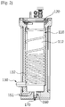
- FIG. 1 is a cross-sectional view illustrating a functional water supply apparatus 100 according to an example embodiment
- FIGS. 2 through 4 are a front view, an exploded view, and a top view, respectively, illustrating a main part of the functional water supply apparatus 100 of FIG. 1
- FIG. 5 is a cross-sectional view cut along line A-A of FIG. 4
- FIG. 6 is a perspective view illustrating a tank cover 121b of a soda water tank 121 of FIG. 5
- FIG. 7 is a perspective view illustrating a cold water guide module 160 and a cold water defrost module 170 of FIG. 6 .
- the functional water supply apparatus 100 includes a cold water supply module 110, a carbonating module 120, a cooling module 130, a hot water supply module 140, a water supply module 150, the cold water guide module 160, and the cold water defrost module 170.
- the example embodiment is described based on an example in which the functional water supply apparatus 100 provides all of cold water CW, hot water HW, and soda water SW, however, is not limited thereto. Combinations of various functional water, such as cold water CW and soda water SW, mineral water and soda water SW, and the like, may be applicable.
- the cold water supply module 110 is configured to supply the cold water CW to an outside.
- the cold water supply module 110 may include a cold water tank 112 and a cold water discharge portion 114.
- the cold water tank 112 refers to a tank for producing and storing the cold water CW. That is, the cold water CW may be produced in the cold water tank 112 by a cooling operation of the cooling module 130. Also, the produced cold water CW may be maintained in a low temperature state by the cooling operation of the cooling module 130 with being stored in the cold water tank 112.
- an inlet 112a through which water flows in from an outside and an outlet 112b through which the cold water CW flows out may be formed on the cold water tank 112.
- the inlet 112a is formed in a lower portion of the cold water tank 112 and the outlet 112b is formed in an upper portion of the cold water tank 112 is described.
- the cold water discharge portion 114 is configured to discharge the cold water CW stored in the cold water tank 112 to an external user that is present outside the apparatus. Accordingly, the cold water discharge portion 114 may be communicably connected to the cold water tank 112.
- the cold water discharge portion 114 may include a cold water discharge line 114b and a cold water discharge valve 114a.
- the cold water discharge line 114b is a cold water discharge path through which the cold water CW in the cold water tank 112 flows in the cold water discharge valve 114a.
- One end of the cold water discharge line 114b may be communicably connected to the outlet 112b of the cold water tank 112, and another end of the cold water discharge line 114a may be communicably connected to the cold water discharge valve 114a.
- the cold water discharge line 114b may be formed to penetrate the carbonating module 120. Accordingly, a leakage prevention structure may be applied to a penetration portion of the cold water discharge line 114b.
- the cold water discharge line 114b may not be withdrawn to the outside through the side of the cold water tank 112. Accordingly, it is possible to prevent interference between the cooling module 130 and the cold water discharge line 114b, and to prevent an increase in a discharge temperature of the cold water CW by minimizing the external exposure of the cold water discharge line 114b. Also, the cooling module 130 may be provided at the side of the cold water tank 112 at maximum tightness thereto without interference from the cold water discharge line 114b. Accordingly, the cold water CW may be further efficiently cooled.
- the cold water discharge valve 114a may selectively discharge the cold water CW flown in through the cold water discharge line 114b to the outside. Accordingly, the cold water discharge valve 114a may be provided in a structure to be opened and closed through direct control of the user.
- the cold water discharge portion 114 may further include a cold water pump provided on the cold water discharge line 114b to forcefully pump the cold water CW, or a cold water flow sensor 114c provided on the cold water discharge line 114b to measure the discharge quantity of cold water CW in real time.
- a cold water pump provided on the cold water discharge line 114b to forcefully pump the cold water CW
- a cold water flow sensor 114c provided on the cold water discharge line 114b to measure the discharge quantity of cold water CW in real time.
- the carbonating module 120 is configured to supply soda water SW to the user.
- the example embodiment in which the carbonating module 120 produces the soda water SW using the cold water CW of the cold water supply module 110 is described.
- the soda water SW may be cooled by the cold water CW of the cooling module 130 and the cold water supply module 110, and maintained in a low temperature state with being stored in the carbonating module 120.
- the carbonating module 120 may be provided to penetrate the cold water supply module 110 at one side of the cold water supply module 110 so that a portion of the carbonating module 120 is in contact with the cold water CW stored in the cold water supply module 110. Accordingly, a portion of the carbonating module 120 may be provided to be encompassed by the cold water stored in the cold water supply module 110.
- a penetration portion 116 may be formed on one side of the cold water supply module 110.
- a portion of the carbonating module 120 may be inserted into and thereby penetrate the penetration portion 116.
- the carbonating module 120 may be provided in a cap shape that shields the penetration portion 116. Accordingly, the carbonating module 120 may be smoothly mounted to or separated from the penetration portion 116 of the cold water supply module 110. Cleaning and maintain and repair of the carbonating module 120 and the cold water supply module 110 may be readily performed.
- the carbonating module 120 may include a soda water tank 121, a cold water supply portion 122, a carbonic acid gas supply portion 126, and a soda water discharge portion 124.
- the soda water tank 121 is a tank that produces and stores the soda water SW.
- a lower portion of the soda water tank 121 is inserted into and thereby penetrates the penetration portion 116 formed in an upper portion of the cold water tank 112 is described. That is, the lower portion of the soda water tank 121 may be inserted into an inside of the cold water tank 112 through the penetration portion 116.
- an upper portion of the soda water tank 121 may couple with the upper portion of the cold water tank 112 to cover and thereby shield the penetration portion 314.
- the soda water tank 121 and the cold water tank 112 may be coupled in a dual tank structure in which two cylindrical tanks are dually disposed at an inner side and an outer side. To this end, the soda water tank 121 may be formed in a container structure with a diameter less than that of the cold water tank 112.
- the penetration portion 116 may be formed in the lower portion or on the side of the cold water tank 112 of the cold water supply module 110.
- a structure in which the penetration portion 116 is formed in the lower portion of the cold water supply module 110 may degrade the cooling effect of the soda water SW due to contact between the water that flows in the cold water tank 112 and the soda water SW.
- a structure in which the penetration portion 116 is formed on the side of the cold water supply module 110 may substantially decrease an installation area of the cooling module 130 and may degrade the cooling performance of the cold water supply module 110.
- the cold water supply portion 122 is configured to supply the cold water CW to an inside of the soda water tank 121.
- the cold water supply portion 122 may be provided between the soda water tank 121 and the cold water discharge portion 114.
- the cold water supply portion 122 may include a cold water supply line 122a, a cold water supply valve 122b, and a cold water supply pump 122c.
- the cold water supply line 122a is a cold water transport path formed between the soda water tank 121 and the cold water discharge portion 114.
- One end of the cold water supply line 122a may be communicably connected to soda water tank 121 and another end of the cold water supply line 122a may be communicably connected to th the cold water discharge line 114b.
- the cold water supply valve 122b is configured to open and close the cold water supply line 122a.
- the cold water supply valve 122b may be provided on the cold water supply line 122a.
- the cold water supply valve 122b may be configured as an electrically controllable solenoid valve.
- the cold water supply pump 122c is configured to pump cold water of the cold water supply line 122a in response to opening of the cold water supply valve 122b.
- the cold water supply pump 122c may be disposed on the cold water supply line 122a.
- the cold water supply pump 122c may operate in response to opening of the cold water supply valve 122b, and may be suspended in response to closing of the cold water supply valve 122b.
- the carbonic acid gas supply portion 126 is configured to supply carbonic acid gas to the inside of the soda water tank 121 at the event of producing the soda water SW.
- the carbonic acid gas supply portion 126 may include a carbonic acid gas supply tank 126a and a carbonic acid gas supply line 126b.
- the carbonic acid gas supply tank 126a may compress and store the carbonic acid gas at high pressure.
- One end of the carbonic acid gas supply line 126b may be communicably connected to the carbonic acid gas supply tank 126a, and another end of the carbonic acid gas supply line 126b may be communicably connected to the soda water tank 121. Accordingly, the carbonic acid gas of the carbonic acid gas supply tank 126a may be supplied to the inside of the soda water tank 121 along the carbonic acid gas supply line 126b.
- check valves 123 and 127 may be provided to the cold water supply line 122a and the carbonic acid gas supply line 126b, respectively. That is, the check valves 123 and 127 may prevent the carbonic acid gas in the soda water tank 121 from flowing backward to the cold water supply line 122a and the carbonic acid gas supply line 126b.
- the soda water discharge portion 124 is configured to discharge the soda water SW stored in the soda water tank 121 to the external user.
- the soda water discharge portion 124 may be communicably connected to the soda water tank 121.
- the soda water discharge portion 124 may include a soda water discharge line 124b and a soda water discharge valve 124a.
- the soda water discharge line 124b is a soda water discharge path through which the soda water SW in the soda water tank 121 flows in the soda water discharge valve 124a.
- One end of the soda water discharge line 124b may be communicably connected to the soda water tank 121, and another end of the soda water discharge line 124b may be communicably connected to the soda water discharge valve 124a.
- the soda water discharge valve 124a may selectively discharge the soda water SW flown in through the soda water discharge line 124b to the outside.
- the soda water discharge valve 124a may be provided in a structure to be opened and closed through direct control of the user.
- the carbonating module 120 may further include a water level sensor 128.
- the water level sensor 128 is configured to sense a water level of the soda water SW stored in the soda water tank 121. Accordingly, an operation of the cold water supply portion 122 and the carbonic acid gas supply portion 126 may be appropriately controlled based on a water level sensing value of the water level sensor 128.
- the water level sensor 128 may be configured as at least one of a float sensor or an electrode sensor. However, it is only an example and a variety of sensor structures capable of sensing a water level of cold water may be applied.
- the soda water tank 121 may include a tank body 121a and a tank cover 121b.
- the tank body 121a may be provided in a container shape for producing and storing the soda water SW.
- the tank body 121a may be inserted into the penetration portion 116 and penetrate the penetration portion 116, and disposed in the cold water tank 112 accordingly.
- the tank body 121a may be provided in a cylindrical shape with a diameter less than that of the cold water tank 112.
- An opening (not shown) to which the tank cover 121b is mounted may be formed on the top surface of the tank body 121a.
- the tank cover 121b may be formed in a shape capable of simultaneously shielding the opening of the tank body 121a and the penetration portion 116 of the cold water tank 112.
- the tank cover 121b may be mounted to or detachable from the upper portion of the tank body 121a and the upper portion of the cold water tank 112.
- the tank cover 121b may fixably couple with the upper portion of the cold water tank 112 and the tank body 121a using a coupling member.
- the tank cover 121b may be formed with a width greater than a width of the upper portion of the cold water tank 112 to cover the upper portion of the cold water tank 112 as well as the tank body 121a of the soda water tank 121.
- a packing member 121c may be provided to the tank cover 121b.
- the packing member 121c is configured to prevent the leakage of soda water SW, cold water CW, and carbonic acid gas through the opening and the penetration portion 116.
- the packing member 121c may be formed using ring-shaped rubber packing to be disposed on the bottom surface of the tank cover 121b.
- the cold water discharge line 114b, the cold water supply line 122a, the carbonic acid gas supply line 126b, the soda water discharge line 124b, the water level sensor 128, and a soda water defrost module 180 and a soda water temperature sensor 182, which will be described below, may be provided to penetrate the tank cover 121b on a central portion of the tank cover 121b.
- the carbonic acid gas supply line 126b may be connected to a pipe member 121d formed to penetrate the tank cover 121b, and the water level sensor 128 may be disposed in the pipe member 121d. Accordingly, the carbonic acid gas supply line 126b and the water level sensor 128 may be installed in a compact structure.
- a partition 121e for partitioning the inner space of the tank body 121a may be provided to the tank cover 121b.
- the partition 121e may protrude downward from the bottom surface of the tank cover 121b.
- the partition 121e may protrude at a length at which the bottom surface of the tank body 121a and a lower portion of the partition 121e are separate from each other when coupling the tank cover 121b and the tank body 121a.
- the inner space of the tank body 121a may be divided into a first space S1 and a second space S2 by way of the partition 121e.
- the first space S1 is a space in which the cold water supply line 122a, the soda water defrost module 180, and the soda water temperature sensor 182 are disposed.
- the second space S2 is a space in which the soda water discharge line 124b, the cold water discharge line 114b, the carbonic acid gas supply line 126b, the pipe member 121d, and the water level sensor 128 are disposed. Accordingly, it is possible to prevent the cold water CW being supplied through the cold water supply line 122a from being immediately discharged through the soda water discharge line 124b.
- the cold water CW may be supplied to the first space S1 through the cold water supply line 122a. Once the cold water CW is supplied to the first space S1, the cold water CW sufficiently mixes with the carbonic acid gas whereby the soda water SW may be produced.
- the soda water SW in the first space S1 may flow in the second space S2 through a space formed between the lower portion of the partition 121e and a floor surface of the tank body 121a.
- the soda water SW in the second space S2 may be discharged to the outside through the soda water discharge line 124b.
- a gap G in which the cold water stored in the cold water tank 112 is to be disposed may be formed between the soda water tank 121 and the cold water tank 112. That is, the tank body 121 a of the soda water tank 121 may be disposed without a tight contact with the inner side of the cold water tank 112. Accordingly, the cold water CW may flow in a space between the cold water tank 112 and the tank body 121a. Accordingly, the side and the lower portion of the tank body 121a may be encompassed by the cold water CW stored in the cold water tank 112. Here, the bottom surface and the side of the tank body 121a may be in contact to enable heat exchange with the cold water CW of the cold water tank 112.
- the soda water SW stored in the tank body 121a may exchange heat with the cold water CW of the cold water tank 112 by way of the tank body 121a. Meanwhile, the cold water tank 112 and the soda water tank 121 may be formed using a material having excellent heat transfer performance. Accordingly, the cooling efficiency of the cold water CW stored in the cold water tank 112 and the cooling efficiency of the soda water SW stored in the soda water tank 121 may be enhanced.
- a gap former 121f configured to form the gap G at a set size may be provided to at least one of the cold water tank 112 and the soda water tank 121.
- the gap former 121 f may serve to form and maintain the gap G between the cold water tank 112 and the soda water tank 121.
- the gap former 121f may serve to stably support the side of the soda water tank 121 in the cold water tank 112.
- the gap former 121f may be provided in a protrusion shape on at least one side of the cold water tank 112 and the soda water tank 121.
- the gap former 121f may protrude at a height corresponding to an interval of the gape G.
- the gap former 121f may be provided as a spacer attached to at least one side of the cold water tank 112 and the soda water tank 121.
- the gap former 121f may be formed to have a thickness corresponding to the interval of the gap G.
- the gap former 121f may be formed to continuously protrude at a set height along the circumference of the tank body 121a, and to this end, an upper portion of the side of the tank body 121a is curved to have a step toward expanding a diameter.
- the cooling module 130 is configured to produce and maintain the cold water CW of the cold water supply module 110 and the soda water SW of the carbonating module 120 at a set temperature or less.
- the cooling module 130 may be provided at the outer side of the cold water supply module 110 and the carbonating module 120.
- the example embodiment in which the cooling module 130 is disposed to encompass the outer circumference of the cold water supply module 110 is described.
- the cooling module 130 may be configured to further cool the cold water supply module 110 rather than the carbonating module 120 since cooling load of the cold water supply module 110 is generally great compared to that of the carbonating module 120. That is, the cold water supply module 110 produces the cold water CW by cooling water of a room temperature, whereas the carbonating module 120 produces the soda water SW through reaction between the cold water CW and the carbonic acid gas. Accordingly, the cooling load of the cold water supply module 110 using the water of the room temperature may be greater than that of the carbonating module 120 using the cold water CW.
- the cooling module 130 may include a compressor (not shown) configured to compress refrigerant, a condenser (not shown) configured to condense the refrigerant compressed at the compressor, an expander (not shown) configured to inflate the refrigerant condensed at the condenser, and an evaporator configured to evaporate the refrigerant inflated at the expander and to guide the refrigerant to the compressor.
- the evaporator may include a cooling pipe 132 in which flow and evaporation of the refrigerant occurs.
- the cooling pipe 132 may be disposed to spirally wind along the outer circumference of the cold water tank 112.
- the cooling pipe 132 may densely wind the lower portion of the cold water tank 112 at a relatively high density compared to the upper portion thereof in which the soda water tank 121 is inserted on the outer side of the cold water tank 112. Accordingly, the cooling pipe 132 of the cooling module 130 may further effectively cool the cold water CW of the cold water tank 112 rather than the soda water SW of the soda water tank 121.
- the cooling module 130 may further include a cold water temperature sensor 134 and a controller 136.
- the cold water temperature sensor 134 may be provided in the cold water tank 112 to measure a temperature of the cold water CW stored in the cold water tank 112 in real time.
- the controller 136 may sense a sensing value of the cold water temperature sensor 134 and may appropriately control an operation of the cooling module 130 based on a sensing value of the soda water temperature sensor 182. It will be described below.
- the hot water supply module 140 is configured to supply the hot water HW to the external user.
- the hot water supply module 140 may include a hot water tank 142, a hot water discharge portion 144, and an auxiliary tank 146.
- the hot water tank 142 is a container configured to produce and store the hot water HW.
- a heater (not shown) for heating the water may be provided in the hot water tank 142. Accordingly, in the hot water tank 142, the heater may produce the hot water HW or maintain the hot water HW at a high temperature by heating the water stored in the hot water tank 142.
- the hot water discharge portion 144 is configured to discharge the hot water HW in the hot water tank 142 to the external user.
- the hot water discharge portion 144 may be communicably connected to the hot water tank 142.
- the hot water discharge portion 144 may include a hot water discharge line 144b and a hot water discharge valve 144a.
- the hot water discharge line 144b is a hot water discharge path through which the hot water HW in the hot water tank 142 flows in the hot water discharge valve 144a.
- One end of the hot water discharge line 144b may be communicably connected to the hot water tank 142, and another end of the hot water discharge line 144b may be communicably connected to the hot water discharge valve 144a.
- the hot water discharge valve 144a may selectively discharge the hot water HW flown in through the hot water discharge line 144b to the outside. Accordingly, the hot water discharge valve 144a may be provided in a structure to be opened and closed through direct control of the user.
- the auxiliary tank 146 is configured to compensate for a sudden increase in internal pressure of the hot water tank 142.
- the auxiliary tank 146 may be communicably provided on one side of the hot water tank 142, and may be formed with a relatively small size compared to the hot water tank 142. Accordingly, if the internal pressure of the hot water tank 142 increases to be a set pressure or more during an operation process of the hot water supply module 140, high-temperature steam produced in the hot water tank 142 may flow in the auxiliary tank 146. If the auxiliary tank 146 is not installed in the hot water tank 142, the hot water tank 142 may have a risk to explode at the event that the internal pressure of the hot water tank 142 increases to be the set pressure or more.
- the water supply module 150 is configured to supply water from an external water source W1 to the hot water supply module 140 and the cold water supply module 110 at a set pressure.
- the water supply module 150 may include a first water supply portion 151,152, 153, 154, 155 and a second water supply portion 156, 157.
- the first water supply portion 151, 152, 153, 154, 155 is configured to supply the water to the cold water tank 112 of the cold water supply module 110.
- the first water supply portion 151,152, 153, 154, 155 may be communicably provided between the cold water tank 112 and the external water source W1.
- the first water supply portion 151,152, 153, 154, 155 may include a first water supply line 151 formed between the cold water tank 112 and the water source W1, a purifying filter 152 disposed on the first water supply line 151 to purify the water being supplied through the first water supply line 151, a first water supply valve 155 disposed on the first water supply line 151 to open and close the first water supply line 151, and a pressure regulator 154 disposed on the first water supply line 151 to adjust the pressure of the water that passes through the first water supply line 151.
- the external water source W1 is tap water that supplies the water at a preset pressure.
- the purifying filter 152 is configured to remove foreign substances and bacteria contained in the tap water and a variety of filters may be used based on a design condition.
- the first water supply valve 155 may be configured as an electrically controllable solenoid valve.
- the pressure regulator 154 may be configured as a pressure reducing valve to appropriately decrease the pressure of the tap water, and may also be omitted or configured to decrease the pressure based on a compression condition of the water source W1 and a peripheral situation.
- a check valve 153 may be provided to the first water supply line 151 to prevent the cold water in the cold water tank 112 from flowing backward toward the first water supply line 151.
- water of a water storage tank may be used as the external water source.
- the water pressure is barely present, which differs from the case in which the tap water is used for the external water source W1.
- a pump to provide the supply pressure of the cold water CW, the hot water HW, and the soda water SH may be additionally installed.
- the second water supply portion 156, 157 is configured to supply water to the hot water tank 142 of the hot water supply module 140.
- the second water supply portion 156, 157 may be connected between the hot water supply module 140 and the first water supply portion 151, 152, 153, 154, 155.
- the second water supply portion 156, 157 may include a second water supply line 156 formed between the hot water tank 142 of the hot water supply module 140 and the first water supply line 151, and a second water supply valve 157 disposed on the second water supply line 156 to open and close the second water supply line 156.
- One end of the second water supply line 156 may be connected to the previous first water supply line 151 of the first water supply valve 155 and another end of the second water supply line 156 may be connected to the hot water tank 142.
- the second water supply valve 157 may be configured as an electrically controllable solenoid valve. Drains 158 and 159 configured to drain the water being supplied to the outside may be provided to the first water supply line 151 and the second water supply line 156, respectively.
- a bypass line 156a may be formed between the first water supply line 151 and the second water supply line 156.
- the bypass line 156a is a path through which the water of the first water supply line 151 flows in the second water supply line 156 through bypassing.
- One end of the bypass line 156a may be connected to the first water supply line 151 after the first water supply valve 155 and another end of the bypass line 156a may be connected to the second water supply line 156 after the second water supply valve 157.
- a bypass valve 156b may be provided on the bypass line 156a. The bypass valve 156b may selectively adjust the flow of water through the bypass line 156a.
- the cold water guide module 160 may configure a cold water flow path F through which the cold water CW flows in the cold water supply module 110.
- the cold water guide module 160 may be accommodated in the cold water supply module 110.
- the cold water flow path F may be formed in a spiral shape from the inlet 112a toward the outlet 112b in the cold water supply module 110.
- the cold water guide module 160 may include a guide bar 162 and a flow guide 164.
- the guide bar 162 may be provided in the cold water supply module 110 to be disposed in a long form from the inlet 112a toward the outlet 112b.
- the guide bar 162 may be provided in a long linear shape and may be disposed vertically in the cold water supply module 110.
- An upper end of the guide bar 162 may be positioned inside the cold water supply module 110, and a lower end of the guide bar 162 may be positioned outside the cold water supply module 110. That is, the lower end of the guide bar 162 may be disposed to penetrate the lower portion of the cold water supply module 110.
- the guide bar 162 may be provided in a pipe structure in which a hollow portion is formed.
- the cold water defrost module 170 may be inserted into the hollow portion of the guide bar 162.
- the upper end of the guide bar 162 may be disposed inside the cold water tank 112 and may be provided in a closed shape to prevent inflow of the cold water CW.
- the lower end of the guide bar 162 may be disposed outside the cold water tank 112, and may be provided in an open shape to enable insertion of the cold water defrost module 170. Accordingly, the cold water defrost module 170 may be inserted into the hollow portion formed in the guide bar 162 through the lower end of the guide bar 162.
- the flow guide 164 may configure the cold water flow path F in a spiral shape along a lengthwise direction of the guide bar 162.
- the flow guide 164 may be provided in a spiral wing shape at outer periphery of the guide bar 162 to make the water spirally flow from the inlet 112a toward the outlet 112b. That is, the water flown in the inlet 112a may spirally circle by the flow guide 164 and may flow in the outlet 112b. During this process, the water may be cooled by the cooling module 130.
- the flow guide 164 may expand a length of a water flow path in the cold water tank 112, thereby securing a sufficient cooling time by the cooling module 130, and may guide the first flown water and subsequently flown water to sequentially flow along the cold water flow path F without being mixed with each other, thereby enhancing the production efficiency of the cold water CW.
- the cold water defrost module 170 is a device configured to prevent the cold water flow path F from being blocked due to freezing of the cold water CW.
- the cold water defrost module 170 may include a heater portion 172 and a power supply portion 174.
- the heater portion 172 may be provided as an electric heater configured to provide heat to the cold water guide module 160 and the cold water CW.
- the example embodiment in which the heater portion 172 is configured as a silicon heater is described, however, it is only an example.
- Various types of heaters may be applicable based on a design condition and circumstance of the functional water supply apparatus 100.
- the heater portion 172 may be disposed in the hollow portion of the guide bar 162 of the cold water guide module 160.
- the heater portion 172 may be disposed at the upper end of the cold water guide module 160, and the cold water guide module 160 and the heater portion 172 may be in tight contact with each other to secure the heat transfer performance.
- the power supply portion 174 may be provided between the heater portion 172 and an external power source to provide the external power to the heater portion 172.
- the power supply portion 174 may be disposed at the outside of the hollow portion of the guide bar 162 of the cold water guide module 160.
- the power supply portion 174 may be disposed at the lower end of the cold water guide module 160, and the power supply portion 174 may be connected to the external power source through a wire (not shown).
- ice I may be produced at a predetermined thickness along the inner circumference of the cold water tank 112 by the cooling module 130. Accordingly, the water flowing in the inlet 112a may be quickly cooled through contact with the ice I during a flowing process along the cold water flow path F.
- the ice I of the cold water flow path F may be formed to have a relatively thick thickness along getting closer to the outlet 112b from the inlet 112a since a temperature of the water flowing in the inlet 112a is higher than that of the cold water CW flowing out through the outlet 112b.
- a discharge space D formed between the cold water guide module 160 and the soda water tank 121 in the cold water tank 112 is a space that communicates with the outlet 112b.
- the temperature of the cold water CW is lowest and a freezing phenomenon of the cold water CW may easily occur and the outlet 112b may be blocked due to the freezing phenomenon of the cold water CW.
- the cold water defrost module 170 may provide heat to the inside of the cold water tank 112. Accordingly, it is possible to prevent the thickness of the ice I formed along the inner circumference of the cold water tank 112 from becoming to be a preset value or more, thereby blocking the cold water flow path F. In addition, it is possible to prevent the freezing phenomenon of the cold water CW from occurring in the discharge space D formed between the cold water guide module 160 and the soda water tank 121, thereby preventing the outlet 112b from being blocked with the ice I. Accordingly, the cold water defrost module 170 may actively secure the production efficiency and production quantity of the cold water CW produced at the cold water supply module 110.
- the cold water defrost module 170 may be appropriately selected based on a sensing value of at least one of the cold water flow sensor 114c or the cold water temperature sensor 134.
- the current discharge quantity of the cold water CW sensed at the cold water flow sensor 114c is less than a set discharge quantity, it may be determined that the cold water flow path F is blocked due to a freezing operation of the cold water CW. Accordingly, the ice I of the cold water flow path F may be melted by operating the cold water defrost module 170. Also, if the current temperature of the cold water CW sensed at the cold water flow sensor 114c is less than a set temperature range, it may be determined that the cold water CW is super-cooled. Accordingly, the temperature of the cold water CW may be appropriately adjusted by operating the cold water defrost module 170.
- the functional water supply apparatus 100 may further include a soda water defrost module 180 configured to prevent sub-cooling or freezing of soda water SW.
- the soda water defrost module 180 may be provided in the soda water tank 121 to provide heat to the soda water SW stored in the soda water tank 121.
- the soda water defrost module 180 may include a soda water heater 184 configured to provide heat to the soda water SW together with the cold water guide module 160.
- the soda water heater 184 may be disposed to penetrate the tank cover 121b on a central portion of the tank cover 121b, and may be communicably connected to the external power source through a wire (not shown).
- the example embodiment describes that the soda water heater 184 is provided as a silicon heater. However, it is only an example and various types of heaters may be used based on a design condition and situation of the functional water supply apparatus 100.
- a current temperature of the soda water SW may be measured in real time through the soda water temperature sensor 182 provided to the tank cover 121b of the carbonating module 120.
- An operation of the soda water defrost module 180 may be appropriately controlled based on a sensing value of the soda water temperature sensor 182.
- a cold water supply process of the functional water supply apparatus 100 operates the cooling module 130 by opening the first water supply valve 155 and by closing the second water supply valve 157.
- the water of the water source W1 flows in the inlet 112a of the cold water tank 112 through the purifying filter 152 and the pressure regulator 154.
- the purifying filter 152 may purify the water and the pressure regulator 154 may appropriately adjust the water pressure.
- the water flown in the cold water tank 112 may flow in the outlet 112b while circling in a spiral form along the cold water flow path F formed by the cold water guide module 160.
- the water may be cooled by the cooling module 130.
- the water may be cooled through direct contact with the ice I produced along the inner circumference of the cold water tank 112.
- the produced cold water CW may be discharged to the cold water discharge line 114b through the outlet 112b.
- the cold water CW in the cold water tank 112 may flow along the cold water discharge line 114b and may be discharged to the external user through the cold water discharge valve 114a.
- the cold water flow sensor 114c measures the discharge quantity of cold water CW discharged through the cold water discharge valve 114a in real time.
- a hot water supply process of the functional water supply apparatus 100 operates the heater by closing the first water supply valve 155 and by opening the second water supply valve 157.
- the water of the water source W1 flows in the hot water tank 142 through the purifying filter 152 and the pressure regulator 154.
- the purifying filter 152 may purify the water and the pressure regulator 154 may appropriately adjust the water pressure.
- the water flown in the hot water tank 142 is heated by the heater and discharged to the hot water discharge line 124b.
- the water in the hot water tank 142 is heated to be a preset temperature or more by the heater.
- the hot water discharge valve 124a If the hot water discharge valve 124a is in an open state, the hot water HW in the hot water tank 142 flows along the hot water discharge line 124b and is discharged to the external user through the hot water discharge valve 124a.
- a soda water supply process of the functional water supply apparatus 100 secures a sufficient amount of cold water CW using the cold water supply module 110. If the amount of cold water CW is determined to be insufficient, the functional water supply apparatus 100 operates the cooling module 130 by opening the first water supply valve 155 and by closing the second water supply valve 157, which is the same as the aforementioned cold water supply process. Accordingly, as in the cold water supply process, the cold water CW is produced and stored in the cold water tank 112.
- the functional water supply apparatus 100 operates the cold water supply pump 122c by closing the cold water discharge valve 114a and by opening the cold water supply valve 122b.
- the cold water supply pump 122c pumps the cold water CW in the cold water tank 112 to the soda water tank 121. Accordingly, the cold water CW in the cold water tank 112 flows along the cold water discharge line 114b and is supplied to the soda water tank 121 through the cold water supply line 122a.
- the carbonic acid gas supply portion 126 supplies carbonic acid gas to the inside of the soda water tank 121
- the cold water CW supplied to the inside of the soda water tank 121 may be produced into the soda water through reaction to the carbonic acid gas.
- the soda water discharge valve 124a is opened, the soda water SW in the soda water tank 121 flows along the soda water discharge line 124b and is discharged to the external user through the soda water discharge valve 124a.
- the functional water supply apparatus 100 is used for a relatively long period of time and the cold water CW is not appropriately withdrawn, the cold water CW or the soda water SW may be super-cooled or frozen by the cooling module 130.
- the cold water CW or the soda water SW may become too cold, which may cause the user to have unpleasant feeling when drinking the cold water CW or the soda water SW.
- a peripheral portion of the cold water flow path F or the outlet 112b may be frozen, which may make flow and discharge of the cold water CW impossible.
- a peripheral portion of an entrance of the soda water discharge line 124b may be frozen, which may make discharge of the soda water SW impossible.
- sub-cooling or freezing of the cold water CW stored in the cold water tank 112 may be sensed based on a sensing value of the cold water temperature sensor 134 and the cold water flow sensor 114c, and an operation of the cold water defrost module 170 may be appropriately determined accordingly. For example, if a sensing value of the cold water temperature sensor 134 is less than a set temperature, the cold water CW may be determined to be super-cooled or frozen and the cold water defrost module 170 may be operated. If a sensing value of the cold water flow sensor 114c is less than a set flow quantity, the cold water CW may be determined to be frozen and the cold water defrost module 170 may be operated.
- the heat generated from the heater portion 172 may be transferred to the inside of the cold water tank 112 by way of the guide bar 162 of the cold water guide module 160. If a temperature of the cold water CW increases, the ice I frozen at the set value or more along the inner circumference of the cold water tank 112 partially melts. Here, if a sensing value of the cold water temperature sensor 134 increases to be a set temperature or more, an operation of the cold water defrost module 170 is suspended.
- sub-cooling or freezing of the soda water SW stored in the soda water tank 121 may be sensed based on a sensing value of the soda water temperature sensor 182, and an operation of the soda water defrost module 180 may be appropriately determined accordingly. For example, if a sensing value of the soda water temperature sensor 182 is less than a set temperature, the soda water SW may be determined to be super-cooled or frozen and the soda water defrost module 180 may be operated.
- the heat generated from the soda water heater 184 may be transferred to the inside of the soda water tank 121 and a temperature of the soda water SW increases.
- a sensing value of the soda water temperature sensor 182 increases to be a set temperature or more, an operation of the soda water defrost module 180 is suspended.
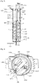
- FIG. 8 illustrates a main part of a functional water supply apparatus 200 according to another example embodiment.
- FIG. 8 Like reference numerals of FIG. 8 as those shown in FIGS. 1 through 6 refer to like constituent elements throughout and a further description will be omitted. Hereinafter, a description is made based on a difference with the functional water supply apparatus 100 shown in FIGS. 1 through 7 .
- a difference between a functional water supply apparatus 200 according to another example embodiment and the functional water supply apparatus 100 shown in FIGS. 1 through 7 lies in that a portion of a cold water guide module 260 and a cold water defrost module 270 extends toward the carbonating module 120, and the soda water defrost module 180 shown in FIGS. 1 through 6 is omitted.
- heat of the cold water defrost module 270 may be provided to the carbonating module 120 as well as the cold water supply module 110, and the cold water defrost module 270 may simultaneously prevent freezing of the cold water CW and the soda water SW.
- the soda water defrost module 180 may be omitted in the example embodiment, which differs from the functional water supply apparatus 100 shown in FIGS. 1 through 7 . Accordingly, it is possible to reduce manufacturing cost by decreasing a number of parts included in the functional water supply apparatus 100.
- an upper end of a guide bar 262 of the cold water guide module 260 may include an extender 266 that extends long toward an upper side.
- a heater portion 272 of the cold water defrost module 270 may be disposed in the extender 266 of the guide bar 262.
- One of an insertion hole portion or insertion groove portion 222 into which an extending portion of the guide bar 262 and the heater portion 272 is to insert may be formed in a lower portion of a tank body 221a of a soda water tank 221.
- the insertion groove portion 222 is formed in the lower portion of the tank body 221a of the soda water tank 221 is described.
- the insertion hole portion may be formed in the lower portion of the soda water tank 221.
- the insertion hole portion is formed in the lower portion of the tank body 221a, the upper end of the guide bar 262 and the heater portion 272 is disposed to penetrate the insertion hole portion. Accordingly, a sealing structure may be installed between the insertion hole portion and the guide bar 262.
- the heater portion 272 may be formed using the same silicon material as the heater portion 272 shown in FIGS. 1 through 7 .
- a single heater portion 272 or a plurality of heater portions 272 may be disposed in a lengthwise direction of the guide bar 262 in a hollow portion of the guide bar 262.
- the heat of the heater portion 272 may be provided to the cold water CW and the soda water SW simultaneously. Accordingly, the cold water defrost module 270 may simultaneously eliminate freezing of the cold water CW and the soda water SW.
- the heat may be selectively provided based on a location of the guide bar 262 by selectively controlling the operation of the heater portions 272.
- the heater portion 272 may include an upper heater 272a disposed in the hollow portion of the extender 266 of the guide bar 262 and a lower heater 272b disposed in a lower portion of the hollow portion of the extender 266 of the guide bar 262.
- the upper heater 272a may perform the same functionality as the soda water defrost module 180 shown in FIGS. 1 through 7
- the lower heater 272b may perform the same functionality as the cold water defrost module 270 shown in FIGS. 1 through 7 .
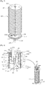
- FIGS. 9 and 10 illustrate a main part of a functional water supply apparatus 300, 400 according to another example embodiment.
- FIGS. 9 and 10 as those shown in FIGS. 1 through 7 refer to like constituent elements throughout and a further description will be omitted. Hereinafter, a description is made based on a difference with the functional water supply apparatus 100 shown in FIGS. 1 through 7 .
- a difference between the functional water supply apparatus 300, 400 according to another example embodiment and the functional water supply apparatus 100 shown in FIGS. 1 through 7 lies in that a carbonating module 320 is provided to be in tight contact with a cold water supply module 310 at an outer side thereof or a carbonating module 420 is completely accommodated in a cold water supply module 410.
- a soda water tank 321 of the carbonating module 320 may be disposed to be in tight side contact with a cold water tank 312 of the cold water supply module 310 at the outer side thereof. Accordingly, soda water SW in the soda water tank 321 may be cooled by the cold water tank 312 by way of a tight contact portion 330 between the soda water tank 321 and the cold water tank 312.
- the tight contact portion 330 refers to a portion on which the cold water tank 312 and the soda water tank 321 are in tight contact with each other, and refers to a portion corresponding to an upper portion of the cold water tank 312 and a lower portion of the soda water tank 321.
- a heat exchange enhancement structure for enhancing the heat exchange performance may be applied to the tight contact portion 330. If the heat exchange performance is enhanced through the tight contact portion 330 between the cold water tank 312 and the soda water tank 321 using the heat exchange enhancement structure, it is possible to enhance the cooling efficiency of the soda water tank 321 by way of the cold water tank 312. Accordingly, it is possible to enhance the cooling performance of the soda water SW stored in the soda water tank 321.
- the heat exchange enhancement structure may be a structure for increasing a heat exchange area of the tight contact portion 330 or a structure for enhancing the heat exchange performance of the tight contact portion 330.
- the heat exchange enhancement structure may be provided on one of an inclined portion, an uneven portion, a protruding portion, or an electric heating portion.
- the inclined portion may be in a structure formed on the tight contact portion 330 to be inclined
- the uneven portion may be in a structure formed on the tight contact portion 330 to be in an uneven shape
- the protruding portion may be in a structure such as a fin, a protrusion, a rib, etc., formed on the tight contact portion 330
- the pre-heating portion may be in a structure formed on the tight contact portion 330 using a material with the excellent heat exchange performance.
- the cold water guide module 160 and the cold water defrost module 170 of FIG. 9 may be provided to the cold water tank 312 in the same structure as the cold water guide module 160 and the cold water defrost module 170 shown in FIGS. 1 through 7 .
- the soda water defrost module 180 of FIG. 9 may be disposed to penetrate the soda water tank 321 in an upper portion of the soda water tank 321 in the same structure as the soda water defrost module 180 shown in FIGS. 1 through 6 . Therefore, according to the example embodiment, the cold water defrost module 170 and the soda water defrost module 180 may provide the heat to the cold water CW and the soda water SW, independently, thereby selectively preventing freezing of the cold water CW and the soda water SW.
- a soda water tank 421 of the carbonating module 420 may be accommodated in a cold water tank 412 of the cold water supply module 410 in a dual tank structure. Accordingly, the soda water tank 421 may be provided in a structure to sink under the cold water CW in the cold water tank 412. Thus, the soda water SW may be cooled by the cold water CW by way of the soda water tank 421.
- the soda water tank 421 of the carbonating module 420 may be formed with a size less than that of the cold water tank 412.
- a gap G may be formed between the soda water tank 421 and an inner side of the cold water tank 412, and the cold water CW may be disposed in the gap G.
- a gap former 421f configured to form the gap G may be provided between the soda water tank 421 and the cold water tank 412.
- the gap former 421f may be provided in a protrusion structure formed on at least one of the cold water tank 412 or the soda water tank 421.
- the gap former 421f in the protrusion shape may protrude at a height corresponding to an interval of the gap G.
- the gap former 421f may be formed on the cold water tank 412, and may be formed on all of the soda water tank 421 and the cold water tank 412.
- a plurality of gap formers 421f may be provided to be separate from each other along the outer circumference of the soda water tank 421.
- the plurality of gap formers 421f may be integrally molded on the side of the soda water tank 421 in an embossing structure.
- structures in a protrusion shape may be mounted on the side of the soda water tank 421.
- a tank support 421g configured to simultaneously set an arrangement location of the soda water tank 421 and to support the soda water tank 421 may be provided in the cold water tank 412. That is, the soda water tank 421 may be inserted into the inside of the cold water tank 412 until the soda water tank 421 is securely received in the tank support 421g. Accordingly, it is possible to appropriately modify the arrangement location of the soda water tank 421, a height of the soda water tank 421, and the like by adjusting a location of the tank support 421g.
- the cold water guide module 260 and the cold water defrost module 270 of FIG. 10 may be provided to the cold water tank 412 in the same structure as the cold water guide module 260 and the cold water defrost module 270 of FIG. 8 .
- the upper end of the guide bar 262 of the cold water guide module 260 may extend long toward the upper side and the extender 266 of the guide bar 262 may be inserted into the insertion groove portion 222 formed in a lower portion of the soda water tank 421 to be in tight contact therewith.
- the cold water defrost module 270 may be disposed in the extender 266 of the guide bar 262. Accordingly, the cold water defrost module 270 may provide the heat to the cold water CW of the cold water tank 412 and the soda water SW of the soda water tank 421 simultaneously, thereby preventing freezing of the cold water CW and the soda water SW.
Landscapes
- Engineering & Computer Science (AREA)
- Chemical & Material Sciences (AREA)
- Physics & Mathematics (AREA)
- Mechanical Engineering (AREA)
- Thermal Sciences (AREA)
- Chemical Kinetics & Catalysis (AREA)
- Combustion & Propulsion (AREA)
- General Engineering & Computer Science (AREA)
- Devices For Dispensing Beverages (AREA)
- Devices That Are Associated With Refrigeration Equipment (AREA)
Applications Claiming Priority (2)
| Application Number | Priority Date | Filing Date | Title |
|---|---|---|---|
| KR1020140099036A KR20150016158A (ko) | 2013-08-02 | 2014-08-01 | 기능수 공급 장치 |
| PCT/KR2014/012399 WO2016017870A1 (fr) | 2014-08-01 | 2014-12-16 | Appareil pour fournir de l'eau fonctionnelle |
Publications (2)
| Publication Number | Publication Date |
|---|---|
| EP3141849A1 true EP3141849A1 (fr) | 2017-03-15 |
| EP3141849A4 EP3141849A4 (fr) | 2017-12-27 |
Family
ID=55221153
Family Applications (1)
| Application Number | Title | Priority Date | Filing Date |
|---|---|---|---|
| EP14898799.3A Withdrawn EP3141849A4 (fr) | 2014-08-01 | 2014-12-16 | Appareil pour fournir de l'eau fonctionnelle |
Country Status (3)
| Country | Link |
|---|---|
| EP (1) | EP3141849A4 (fr) |
| KR (1) | KR20150016158A (fr) |
| WO (1) | WO2016017870A1 (fr) |
Cited By (2)
| Publication number | Priority date | Publication date | Assignee | Title |
|---|---|---|---|---|
| EP3896374A1 (fr) * | 2020-04-17 | 2021-10-20 | Xiamen Aquasu Electric Shower Co., Ltd. | Dispositif de sortie d'eau |
| US12264060B2 (en) | 2019-04-30 | 2025-04-01 | Coway Co., Ltd. | Cold water production apparatus and method |
Families Citing this family (3)
| Publication number | Priority date | Publication date | Assignee | Title |
|---|---|---|---|---|
| KR101671286B1 (ko) * | 2015-08-31 | 2016-11-03 | (주)아이티로그 | 탄산수 정수기용 혼합탱크 |
| CN109549479A (zh) * | 2017-09-27 | 2019-04-02 | 佛山市顺德区美的饮水机制造有限公司 | 水处理装置 |
| CN113280651B (zh) * | 2021-07-22 | 2021-09-17 | 四川空分设备(集团)有限责任公司 | 绕管式换热器 |
Family Cites Families (8)
| Publication number | Priority date | Publication date | Assignee | Title |
|---|---|---|---|---|
| US2531315A (en) * | 1946-08-08 | 1950-11-21 | Temprite Products Corp | Liquid cooling apparatus |
| KR100487816B1 (ko) * | 2002-12-31 | 2005-05-10 | 워터로직매뉴팩쳐링(주) | 물 공급기 |
| KR100735914B1 (ko) * | 2006-02-22 | 2007-07-04 | 주식회사 영원코퍼레이션 | 물공급 장치 |
| KR101100648B1 (ko) * | 2008-11-18 | 2012-01-03 | 주식회사 영원코퍼레이션 | 물 공급 장치 |
| KR20110079947A (ko) * | 2010-01-04 | 2011-07-12 | 웅진코웨이주식회사 | 빙축열조 및 이를 구비하는 정수기 |
| JP2012002376A (ja) * | 2010-06-14 | 2012-01-05 | Fuji Electric Retail Systems Co Ltd | 飲料冷却装置 |
| RU2629868C2 (ru) * | 2012-09-13 | 2017-09-04 | Страусс Уотер Лтд. | Дозирующее устройство для напитков с системой газирования |
| KR101419751B1 (ko) * | 2012-10-18 | 2014-07-15 | 주식회사 위닉스 | 순간 냉각장치 |
-
2014
- 2014-08-01 KR KR1020140099036A patent/KR20150016158A/ko not_active Ceased
- 2014-12-16 WO PCT/KR2014/012399 patent/WO2016017870A1/fr not_active Ceased
- 2014-12-16 EP EP14898799.3A patent/EP3141849A4/fr not_active Withdrawn
Cited By (3)
| Publication number | Priority date | Publication date | Assignee | Title |
|---|---|---|---|---|
| US12264060B2 (en) | 2019-04-30 | 2025-04-01 | Coway Co., Ltd. | Cold water production apparatus and method |
| EP3896374A1 (fr) * | 2020-04-17 | 2021-10-20 | Xiamen Aquasu Electric Shower Co., Ltd. | Dispositif de sortie d'eau |
| AU2021202214B2 (en) * | 2020-04-17 | 2023-04-06 | Xiamen Aquasu Electric Shower Co., Ltd. | Water output device |
Also Published As
| Publication number | Publication date |
|---|---|
| EP3141849A4 (fr) | 2017-12-27 |
| KR20150016158A (ko) | 2015-02-11 |
| WO2016017870A1 (fr) | 2016-02-04 |
Similar Documents
| Publication | Publication Date | Title |
|---|---|---|
| EP3141849A1 (fr) | Appareil pour fournir de l'eau fonctionnelle | |
| JP5933040B2 (ja) | 飲料冷却装置およびこの冷却装置を用いた飲料供給システム | |
| US9897374B2 (en) | Cold water tank | |
| KR101884736B1 (ko) | 언더 싱크형 먹는물 공급장치 | |
| KR20180045754A (ko) | 언더 싱크형 먹는물 공급장치 | |
| CN108272346A (zh) | 嵌入式净饮机 | |
| US20120318823A1 (en) | Hot water supply device and cold/hot water dispenser using the same | |
| KR101059879B1 (ko) | 히터 및 온수공급장치 | |
| US11465081B2 (en) | Water filtering and recycling system for ice making appliance | |
| JP2010002061A (ja) | 貯湯式温水器 | |
| KR20070108768A (ko) | 급수장치 및 이를 포함하는 냉장고 | |
| CN114158935A (zh) | 多功能饮水机的水箱组件和多功能饮水机 | |
| CN208905548U (zh) | 嵌入式净饮机 | |
| KR20130006240A (ko) | 정수기 | |
| CN208905556U (zh) | 嵌入式净饮机 | |
| CN109419362B (zh) | 饮用水供给装置 | |
| US20240053056A1 (en) | Hot water generation apparatus, water purifier comprising same, and method for controlling hot water generation apparatus | |
| CN216494869U (zh) | 多功能饮水机的水箱组件和多功能饮水机 | |
| KR100716469B1 (ko) | 온수 역류방지 기능을 가지는 냉온수기 | |
| CN208905555U (zh) | 嵌入式净饮机 | |
| KR200230320Y1 (ko) | 냉온수기 | |
| KR101749964B1 (ko) | 냉동싸이클을 이용한 순간 냉각장치 | |
| KR20170123136A (ko) | 하나의 냉각 사이클로 냉수 및 탄산수를 제공할 수 있는 음용수 공급기 | |
| KR102763000B1 (ko) | 정수기의 제어 방법 | |
| KR100894475B1 (ko) | 온수 공급 기능을 구비한 냉장고 |
Legal Events
| Date | Code | Title | Description |
|---|---|---|---|
| PUAI | Public reference made under article 153(3) epc to a published international application that has entered the european phase |
Free format text: ORIGINAL CODE: 0009012 |
|
| 17P | Request for examination filed |
Effective date: 20161208 |
|
| AK | Designated contracting states |
Kind code of ref document: A1 Designated state(s): AL AT BE BG CH CY CZ DE DK EE ES FI FR GB GR HR HU IE IS IT LI LT LU LV MC MK MT NL NO PL PT RO RS SE SI SK SM TR |
|
| AX | Request for extension of the european patent |
Extension state: BA ME |
|
| RIN1 | Information on inventor provided before grant (corrected) |
Inventor name: YOON, HEE JONG |
|
| DAX | Request for extension of the european patent (deleted) | ||
| A4 | Supplementary search report drawn up and despatched |
Effective date: 20171127 |
|
| RIC1 | Information provided on ipc code assigned before grant |
Ipc: B67D 3/00 20060101ALI20171121BHEP Ipc: F28D 7/02 20060101ALN20171121BHEP Ipc: B01F 3/04 20060101ALI20171121BHEP Ipc: B67D 1/08 20060101ALI20171121BHEP Ipc: F25D 31/00 20060101AFI20171121BHEP Ipc: B67D 1/00 20060101ALI20171121BHEP Ipc: F28F 19/00 20060101ALN20171121BHEP Ipc: F25D 21/04 20060101ALN20171121BHEP |
|
| STAA | Information on the status of an ep patent application or granted ep patent |
Free format text: STATUS: THE APPLICATION IS DEEMED TO BE WITHDRAWN |
|
| 18D | Application deemed to be withdrawn |
Effective date: 20190702 |