EP3141859B1 - Mikrokanalwärmetauscher - Google Patents
Mikrokanalwärmetauscher Download PDFInfo
- Publication number
- EP3141859B1 EP3141859B1 EP16188061.2A EP16188061A EP3141859B1 EP 3141859 B1 EP3141859 B1 EP 3141859B1 EP 16188061 A EP16188061 A EP 16188061A EP 3141859 B1 EP3141859 B1 EP 3141859B1
- Authority
- EP
- European Patent Office
- Prior art keywords
- pass
- heat exchange
- exchange module
- disposed
- hole
- Prior art date
- Legal status (The legal status is an assumption and is not a legal conclusion. Google has not performed a legal analysis and makes no representation as to the accuracy of the status listed.)
- Not-in-force
Links
Images


Classifications
-
- F—MECHANICAL ENGINEERING; LIGHTING; HEATING; WEAPONS; BLASTING
- F28—HEAT EXCHANGE IN GENERAL
- F28D—HEAT-EXCHANGE APPARATUS, NOT PROVIDED FOR IN ANOTHER SUBCLASS, IN WHICH THE HEAT-EXCHANGE MEDIA DO NOT COME INTO DIRECT CONTACT
- F28D1/00—Heat-exchange apparatus having stationary conduit assemblies for one heat-exchange medium only, the media being in contact with different sides of the conduit wall, in which the other heat-exchange medium is a large body of fluid, e.g. domestic or motor car radiators
- F28D1/02—Heat-exchange apparatus having stationary conduit assemblies for one heat-exchange medium only, the media being in contact with different sides of the conduit wall, in which the other heat-exchange medium is a large body of fluid, e.g. domestic or motor car radiators with heat-exchange conduits immersed in the body of fluid
- F28D1/04—Heat-exchange apparatus having stationary conduit assemblies for one heat-exchange medium only, the media being in contact with different sides of the conduit wall, in which the other heat-exchange medium is a large body of fluid, e.g. domestic or motor car radiators with heat-exchange conduits immersed in the body of fluid with tubular conduits
- F28D1/053—Heat-exchange apparatus having stationary conduit assemblies for one heat-exchange medium only, the media being in contact with different sides of the conduit wall, in which the other heat-exchange medium is a large body of fluid, e.g. domestic or motor car radiators with heat-exchange conduits immersed in the body of fluid with tubular conduits the conduits being straight
- F28D1/0535—Heat-exchange apparatus having stationary conduit assemblies for one heat-exchange medium only, the media being in contact with different sides of the conduit wall, in which the other heat-exchange medium is a large body of fluid, e.g. domestic or motor car radiators with heat-exchange conduits immersed in the body of fluid with tubular conduits the conduits being straight the conduits having a non-circular cross-section
- F28D1/05366—Assemblies of conduits connected to common headers, e.g. core type radiators
- F28D1/05391—Assemblies of conduits connected to common headers, e.g. core type radiators with multiple rows of conduits or with multi-channel conduits combined with a particular flow pattern, e.g. multi-row multi-stage radiators
-
- F—MECHANICAL ENGINEERING; LIGHTING; HEATING; WEAPONS; BLASTING
- F28—HEAT EXCHANGE IN GENERAL
- F28D—HEAT-EXCHANGE APPARATUS, NOT PROVIDED FOR IN ANOTHER SUBCLASS, IN WHICH THE HEAT-EXCHANGE MEDIA DO NOT COME INTO DIRECT CONTACT
- F28D1/00—Heat-exchange apparatus having stationary conduit assemblies for one heat-exchange medium only, the media being in contact with different sides of the conduit wall, in which the other heat-exchange medium is a large body of fluid, e.g. domestic or motor car radiators
- F28D1/02—Heat-exchange apparatus having stationary conduit assemblies for one heat-exchange medium only, the media being in contact with different sides of the conduit wall, in which the other heat-exchange medium is a large body of fluid, e.g. domestic or motor car radiators with heat-exchange conduits immersed in the body of fluid
- F28D1/04—Heat-exchange apparatus having stationary conduit assemblies for one heat-exchange medium only, the media being in contact with different sides of the conduit wall, in which the other heat-exchange medium is a large body of fluid, e.g. domestic or motor car radiators with heat-exchange conduits immersed in the body of fluid with tubular conduits
- F28D1/0408—Multi-circuit heat exchangers, e.g. integrating different heat exchange sections in the same unit or heat exchangers for more than two fluids
- F28D1/0417—Multi-circuit heat exchangers, e.g. integrating different heat exchange sections in the same unit or heat exchangers for more than two fluids with particular circuits for the same heat exchange medium, e.g. with the heat exchange medium flowing through sections having different heat exchange capacities or for heating/cooling the heat exchange medium at different temperatures
-
- F—MECHANICAL ENGINEERING; LIGHTING; HEATING; WEAPONS; BLASTING
- F28—HEAT EXCHANGE IN GENERAL
- F28D—HEAT-EXCHANGE APPARATUS, NOT PROVIDED FOR IN ANOTHER SUBCLASS, IN WHICH THE HEAT-EXCHANGE MEDIA DO NOT COME INTO DIRECT CONTACT
- F28D1/00—Heat-exchange apparatus having stationary conduit assemblies for one heat-exchange medium only, the media being in contact with different sides of the conduit wall, in which the other heat-exchange medium is a large body of fluid, e.g. domestic or motor car radiators
- F28D1/02—Heat-exchange apparatus having stationary conduit assemblies for one heat-exchange medium only, the media being in contact with different sides of the conduit wall, in which the other heat-exchange medium is a large body of fluid, e.g. domestic or motor car radiators with heat-exchange conduits immersed in the body of fluid
- F28D1/04—Heat-exchange apparatus having stationary conduit assemblies for one heat-exchange medium only, the media being in contact with different sides of the conduit wall, in which the other heat-exchange medium is a large body of fluid, e.g. domestic or motor car radiators with heat-exchange conduits immersed in the body of fluid with tubular conduits
- F28D1/0408—Multi-circuit heat exchangers, e.g. integrating different heat exchange sections in the same unit or heat exchangers for more than two fluids
- F28D1/0426—Multi-circuit heat exchangers, e.g. integrating different heat exchange sections in the same unit or heat exchangers for more than two fluids with units having particular arrangement relative to the large body of fluid, e.g. with interleaved units or with adjacent heat exchange units in common air flow or with units extending at an angle to each other or with units arranged around a central element
- F28D1/0435—Combination of units extending one behind the other
-
- F—MECHANICAL ENGINEERING; LIGHTING; HEATING; WEAPONS; BLASTING
- F28—HEAT EXCHANGE IN GENERAL
- F28F—DETAILS OF HEAT-EXCHANGE AND HEAT-TRANSFER APPARATUS, OF GENERAL APPLICATION
- F28F1/00—Tubular elements; Assemblies of tubular elements
- F28F1/10—Tubular elements and assemblies thereof with means for increasing heat-transfer area, e.g. with fins, with projections, with recesses
- F28F1/12—Tubular elements and assemblies thereof with means for increasing heat-transfer area, e.g. with fins, with projections, with recesses the means being only outside the tubular element
- F28F1/124—Tubular elements and assemblies thereof with means for increasing heat-transfer area, e.g. with fins, with projections, with recesses the means being only outside the tubular element and being formed of pins
-
- F—MECHANICAL ENGINEERING; LIGHTING; HEATING; WEAPONS; BLASTING
- F28—HEAT EXCHANGE IN GENERAL
- F28F—DETAILS OF HEAT-EXCHANGE AND HEAT-TRANSFER APPARATUS, OF GENERAL APPLICATION
- F28F9/00—Casings; Header boxes; Auxiliary supports for elements; Auxiliary members within casings
- F28F9/02—Header boxes; End plates
- F28F9/0202—Header boxes having their inner space divided by partitions
- F28F9/0204—Header boxes having their inner space divided by partitions for elongated header box, e.g. with transversal and longitudinal partitions
- F28F9/0209—Header boxes having their inner space divided by partitions for elongated header box, e.g. with transversal and longitudinal partitions having only transversal partitions
- F28F9/0212—Header boxes having their inner space divided by partitions for elongated header box, e.g. with transversal and longitudinal partitions having only transversal partitions the partitions being separate elements attached to header boxes
-
- F—MECHANICAL ENGINEERING; LIGHTING; HEATING; WEAPONS; BLASTING
- F28—HEAT EXCHANGE IN GENERAL
- F28D—HEAT-EXCHANGE APPARATUS, NOT PROVIDED FOR IN ANOTHER SUBCLASS, IN WHICH THE HEAT-EXCHANGE MEDIA DO NOT COME INTO DIRECT CONTACT
- F28D21/00—Heat-exchange apparatus not covered by any of the groups F28D1/00 - F28D20/00
- F28D2021/0019—Other heat exchangers for particular applications; Heat exchange systems not otherwise provided for
- F28D2021/0068—Other heat exchangers for particular applications; Heat exchange systems not otherwise provided for for refrigerant cycles
- F28D2021/0071—Evaporators
-
- F—MECHANICAL ENGINEERING; LIGHTING; HEATING; WEAPONS; BLASTING
- F28—HEAT EXCHANGE IN GENERAL
- F28F—DETAILS OF HEAT-EXCHANGE AND HEAT-TRANSFER APPARATUS, OF GENERAL APPLICATION
- F28F2260/00—Heat exchangers or heat exchange elements having special size, e.g. microstructures
- F28F2260/02—Heat exchangers or heat exchange elements having special size, e.g. microstructures having microchannels
-
- F—MECHANICAL ENGINEERING; LIGHTING; HEATING; WEAPONS; BLASTING
- F28—HEAT EXCHANGE IN GENERAL
- F28F—DETAILS OF HEAT-EXCHANGE AND HEAT-TRANSFER APPARATUS, OF GENERAL APPLICATION
- F28F2270/00—Thermal insulation; Thermal decoupling
Definitions
- Embodiments of the present invention relate to a micro channel type heat exchanger.
- a heat exchanger may be used as a condenser or evaporator in a freezing cycle device including a compressor, a condenser, an expansion unit, and an evaporator.
- the heat exchanger is installed on a vehicle, a refrigerator, etc. and thermally exchanges a refrigerant with air.
- the heat exchanger may be divided into a fin tube type heat exchanger and a micro channel type heat exchanger depending on its structure.
- the fin tube type heat exchanger is made of copper and the micro channel type heat exchanger is made of aluminum.
- the micro channel type heat exchanger has better efficiency than the fin tube type heat exchanger because a fine flow channel is formed therein.
- the fin tube type heat exchanger can be easily fabricated because a fin and a tube are welded.
- the micro channel type heat exchanger has a disadvantage in that initial investment costs according to fabrication are high because it is put into a furnace and fabricated through brazing.
- the fin tube type heat exchanger can be easily fabricated with them stacked in two columns because it can be easily fabricated, whereas the micro channel type heat exchanger has a difficulty in fabrication in two columns because it is put into a furnace and fabricated.
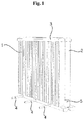
- FIG. 1 is a perspective view of a conventional micro channel type heat exchanger.
- the conventional micro channel type heat exchanger includes a first column 1 and a second column 2, and includes a header 3 connecting the first column 1 and the second column 2.
- the header 3 provides a flow channel for changing the direction of the refrigerant of the first column 1 to the second column 2.
- the inflow hole 4 of a refrigerant is disposed below the first column 1, and the discharge hole 5 of a refrigerant on the lower side of the second column 2.
- a refrigerant is supplied to the first column 1 through a plurality of flow channels.
- a refrigerant flows from bottom to top.
- the refrigerant passes through the header 3 and flows from top to bottom.
- a single discharge hole 5 is disposed. That is, fluids passing through the first column 1 are joined in some place of the second column 2, collected in the discharge hole 5, and then discharged.
- Korean Patent No. 10-0765557 shows a conventional heat exchanger.
- JP 2004 18960 A relates to a heat exchanger comprising a heat exchanger body having a pair of aluminum header pipes, a plurality of heat exchange tubes installed parallel with each other between these header pipes, a corrugated fin disposed between the heat exchange tubes, and an aluminum connection member formed by integrating a plate-like base part having a joining surface in contact with the side face of the header pipe with a plurality of refrigerant flow parts projectedly installed on the plate-like base part and communicating with the plurality of inflow ports and outflow ports for refrigerant formed in the header pipe.
- JP 2014 001896 A relates to an indoor heat exchanger for a vehicle comprising a first tube and a second tube being connected between a first header tank and a second header tank, and fins are installed in the tubes to form core portions, respectively.
- EP 0 414 433 A2 relates to a duplex heat exchanger comprising unit heat exchangers which have a plurality of tubes arranged parallel with each other and comprise fins each interposed between two adjacent ones of such tubes, opposite ends of each tube being connected to a pair of headers in fluid connection therewith.
- JP Hll 142087 A relates to a heat exchanger comprising connection holes which are confronted with each other provided on confronted surfaces of peripheral walls of headers of first and second heat-exchanger cores. Then, these both connection holes are communicated and connected through a communication hole by pinching a joint member made of an aluminum extrusion-molded material having the straight communication hole, between both headers.
- WO 2014/189112 A1 relates to a connection member including two identically shaped long and narrow plate members.
- a plurality of communicating holes having boss parts protruding cylindrically are being formed in a row by burring on one surface of each of the plate members, and the plate members are bonded to each other back-to-back.
- a connection member is disposed between the two communicating header tanks. Boss parts are inserted into holes formed in the header tanks and are bonded to the header tanks.
- An embodiment of the present invention is directed to the provision of a micro channel type heat exchanger capable of minimizing a thermal loss through a fixed plate for separating headers.
- An embodiment of the present invention is directed to the provision of a micro channel type heat exchanger having a structure capable of reducing a pressure loss of a refrigerant if it is used as an evaporator.
- An embodiment of the present invention is directed to the provision of a micro channel type heat exchanger having a structure capable of operating as a single pass in two stacked heat exchange modules.
- micro channel type heat exchanger acoording to claim 1.
- Advantageous embodiments of the invention are defined in claims 2-9.
- a micro channel type heat exchanger according a first embodiment is described with reference to FIGS. 2 to 7 .
- An air-conditioner includes a compressor 10 configured to compress a refrigerant, a condensation heat exchanger 26 configured to be supplied with the refrigerant from the compressor 10 and to condense the supplied refrigerant, an expansion unit 23 configured to expand the fluid refrigerant condensed by the condensation heat exchanger, and an evaporation heat exchanger 20 configured to evaporate the refrigerant expanded by the expansion unit 23.
- an electronic expansion valve eev
- a Bi-flow valve a capillary tube
- a capillary tube a capillary tube
- the air-conditioner may further include a condensation ventilation fan 11 configured to flow air into the condensation heat exchanger 26 and an evaporation ventilation fan 12 configured to flow air into the evaporation heat exchanger 20.
- An accumulator (not shown) may be installed between the evaporation heat exchanger 20 and the compressor 10.
- the accumulator stores a fluid refrigerant and supplies only a gaseous refrigerant to the compressor 10.
- the evaporation heat exchanger 20 is a micro channel type heat exchanger.
- the evaporation heat exchanger 20 is fabricated in two columns and has a stacked dual pass.
- the evaporation heat exchanger 20 is made of aluminum.
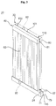
- the evaporation heat exchanger 20 has a first heat exchange module 30 and a second heat exchange module 40 stacked thereon.
- the first heat exchange module 30 and the second heat exchange module 40 stand vertically and are stacked front and back in the upright state.
- a refrigerant flows from top to bottom or from bottom to top.
- the refrigerant flows from the first heat exchange module 30 to the second heat exchange module 40.
- heat blocking members 100 and 105 for blocking or reducing the thermal conduction of the first heat exchange module 30 and the second heat exchange module 40 are installed.
- the heat blocking member may be made of a material having low heat conductivity.
- the heat blocking member has a plate form and is inserted between the first heat exchange module 30 and the second heat exchange module 40.
- the heat blocking member may be fabricated in various forms.
- the heat blocking member may be formed in a square, circle or ellipse form.
- the heat blocking members 100 and 105 separate the first heat exchange module 30 and the second heat exchange module 40.
- the heat blocking members 100 and 105 prevent the first heat exchange module 30 and the second heat exchange module 40 from directly coming into contact with each other.
- the heat blocking members 100 and 105 are disposed between the first heat exchange module 30 and the second heat exchange module 40, and connect the first heat exchange module 30 and the second heat exchange module 40.
- the configuration of the first heat exchange module 30 is basically described because the first heat exchange module 30 and the second heat exchange module 40 have a similar configuration.
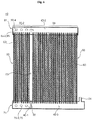
- the first heat exchange module 30 includes a plurality of flat tubes 50 configured to have a plurality of flow channels formed therein, a fin 60 configured to connect the flat tubes 50 and to conduct heat, a first lower header 70 connected to one side of the plurality of flat tubes 50 and configured to communicate with one side of the plurality of flat tubes 50 so that a refrigerant flows therein, a first upper header 80 connected to the other side of the plurality of flat tubes 50 and configured to communicate with the other side of the plurality of flat tubes 50 so that a refrigerant flows therein, and a baffle 90 formed in at least any one of the first lower header 70 and the first upper header 80 and configured to partition the inside of the first lower header 70 or the first upper header 80 so that a flow of a refrigerant is blocked.
- the second heat exchange module 40 includes a plurality of flat tubes 50 configured to have a plurality of flow channels formed therein, a fin 60 configured to connect the flat tubes 50 and conduct heat, a second lower header 71 connected to one side of the plurality of flat tubes 50 and configured to communicate with one side of the plurality of flat tubes 50 so that a refrigerant flows therein, a second upper header 81 connected to the other side of the plurality of flat tubes 50 and configured to communicate with the other side of the plurality of flat tubes 50 so that a refrigerant flows therein, and a baffle 90 formed in at least ant one of the second lower header 71 and the second upper header 81 and configured to partition the inside of the second lower header 71 or the second upper header 81 so that a flow of a refrigerant is blocked.
- the flat tubes 50 are made of metal.
- the flat tube 40 is made of aluminum.
- the first lower header 70 and the first upper header 80 are also made of aluminum.
- the elements of the first heat exchange module 30 may be made of another metal, such as copper.
- a plurality of the flow channels is formed within the flat tube 50.
- the flow channel of the flat tube 50 is lengthily extended in the length direction thereof.
- the flat tube 50 is vertically disposed, and a refrigerant flows up and down.
- the flow channel of the flat tube 50 is lengthily extended in the length direction thereof.
- the plurality of flat tubes 50 is stacked left and right.
- the upper side of the flat tube 50 is inserted into the first upper header 80 and communicates with the inside of the first upper header 80.
- the lower side of the flat tube 50 is inserted into the first lower header 70 and communicates with the inside of the first lower header 70.
- the fin 60 is made of metal and conducts heat.
- the fin 60 may be made of the same material as the flat tube 50. In the present embodiment, the fin 60 may be made of aluminum.
- the fin 60 comes into contact with two flat tubes 50.
- the fin 60 is disposed between the two flat tubes 50.
- the fin 60 may be curved and formed.
- the fin 60 connects the two flat tubes 50 that are stacked left and right and conducts heat.
- the baffle 90 functions to change the flow direction of a refrigerant.
- the direction of a refrigerant that flows from the left of the baffle 90 and the direction of a refrigerant that flows from the right of the baffle 90 are opposite.
- a first pass 31, a second pass 32, and part of a third pass 33 are formed in the first heat exchange module 30.
- the remainder of the third pass 33 and a fourth pass 34 are formed in the second heat exchange module 40.
- part of the third pass 33 formed in the first heat exchange module 30 is defined as a (3-1)-th pass 33-1, and the remainder of the third pass 33 formed in the second heat exchange module 40 is defined as a (3-2)-th pass 33-2.
- the (3-1)-th pass 33-1 and the (3-2)-th pass 33-2 are physically separated and disposed in the first heat exchange module 30 and the second heat exchange module 40, but operate like a single pass.
- the (3-1)-th pass 33-1 and the (3-2)-th pass 33-2 operate as a single pass, but are distributed and disposed in the two heat exchange modules 30 and 40.
- the (3-1)-th pass 33-1 and the (3-2)-th pass 33-2 operate like a single pass, but are stacked and installed.
- a ratio of the third pass 33 to all the passes can be easily controlled because the (3-1)-th pass 33-1 and the (3-2)-th pass 33-2 can be distributed and installed on the two heat exchange modules 30 and 40.
- a ratio of the third pass 33 can be controlled in the state in which the number of flat tubes 50 of the first heat exchange module 30 and the number of flat tubes 50 of the second heat exchange module 40 are identically configured.
- the flat tubes 50 of the first pass 31 and the second pass 32 are physically separated.
- a space for physically separating the passes is defined as a separation space.
- a separated space is formed between the first pass 31 and the second pass 32, which is defined as a first separation space 61.
- a separated space is also formed between the second pass 32 and the (3-1)-th pass 33-1, which is defined as a second separation space 62.
- a separated space is also formed between the (3-2)-th pass 33-2 and the fourth pass 34, which is defined as a third separation space 63.
- the separation spaces 61, 62 and 63 block heat from being delivered to an adjacent pass.
- the separation spaces 61, 62 and 63 may block heat from being delivered to an adjacent flat tube.
- the separation spaces 61, 62 and 63 may be formed by not forming a fin 60 connecting the flat tubes 50.
- the baffle 90 is disposed on the upper or lower side of the separation spaces 61, 62 and 63.
- the direction of a refrigerant in the passes may be changed in the upper header 80, 81 or the lower header 70, 71.
- the baffle 90 may be disposed in the upper header 80, 81 or the lower header 70, 71 in order to change the direction of a refrigerant.
- an inflow pipe 22 is connected to the first pass 31, and a discharge pipe 24 is connected to the fourth pass 34.
- the baffle 90 includes a first baffle 91 configured to partition the first pass 31 and the second pass 32, a second baffle 92 configured to partition the second pass 32 and the (3-1)-th pass 33-1, and a third baffle 93 configured to partition the (3-2)-th pass 33-2 and the fourth pass 34.
- the first baffle 91 and the second baffle 92 are disposed in the first heat exchange module 30, and the third baffle 93 is disposed in the second heat exchange module 40.
- the number and locations of the baffles may be changed.
- the (3-1)-th pass 33-1 and the (3-2)-th pass 33-2 are disposed in different heat exchange modules, but refrigerants in the (3-1)-th pass 33-1 and the (3-2)-th pass 33-2 flow in the same direction.
- the first baffle 91 is disposed within the first lower header 70
- the second baffle 92 is disposed within the first upper header 80
- the third baffle 93 is disposed within the second lower header 71.
- the inflow pipe 22 is located in the first lower header 70 of the first pass 31.
- the discharge pipe 24 is located in the second lower header 71 of the fourth pass 34. If the locations of the inflow pipe 22 and the discharge pipe 24 are changed, the location where the baffle 90 is installed may be changed.
- the plurality of heat exchange modules i.e., the first heat exchange module 30 and the second heat exchange module 40
- the third pass 33 is disposed in the plurality of heat exchange modules.
- the inside of the first lower header 70 is partitioned into a (1-1)-th space 30-1 and a (1-3)-th space 30-3 by the first baffle 91.
- the inside of the first upper header 80 is partitioned into a (1-2)-th space 30-2 and a (1-4)-th space 30-4 by the second baffle 92.
- the inside of the second lower header 71 is partitioned into a (2-1)-th space 40-1 and a (2-3)-th space 40-3 by the third baffle 93.
- a baffle is not disposed within the second upper header 81.
- the inside of the second upper header 81 is defined as a (2-2)-th space 40-2.
- the inflow pipe 22 is connected to the (1-1)-th space 30-1.
- the discharge pipe 24 is connected to the (2-3)-th space 40-3.
- the (3-1)-th pass 33-1 and the (3-2)-th pass 33-2 are connected through the first lower header 70 and the second lower header 71 and are connected through the first upper header 80 and the second upper header 81.
- a lower hole 75 is formed in order to flow a refrigerant to another heat exchange module.
- the lower hole 75 connects the first lower header 70 and the second lower header 71 and flows a refrigerant.
- a refrigerant may flow in another heat exchange module through the lower hole 75.
- a pipe may be installed in the lower hole 75, and the pipe may connect the lower holes 75.
- the lower hole 75 directly connects the (1-3)-th space 30-3 and the (2-1)-th space 40-1.
- the lower hole 75 formed in the first heat exchange module 30 is defined as a first lower hole 75-1
- the lower hole 75 formed in the second heat exchange module 40 is defined as a second lower hole 75-2.
- the first and the second lower holes 75-1 and 75-2 connect the second pass 32 and the (3-2)-th pass 33-2.
- the first and the second lower holes 75-1 and 75-2 are connected. Accordingly, separate welding for connecting the first and the second lower holes 75-1 and 75-2 is not performed.
- a manufacturing cost and a manufacturing time can be reduced because the first and the second lower holes 75-1 and 75-2 are directly bonded without using a pipe.
- a plurality of the first lower holes 75-1 and the second lower holes 75-2 may be formed so that a flow from the first heat exchange module 30 to the second heat exchange module 40 is smooth.
- an upper hole 85 that connects the first upper header 80 and the second upper header 81 is formed.
- the upper hole 85 formed in the first heat exchange module 30 is defined as a first upper hole 85-1
- the upper hole 85 formed in the second heat exchange module 40 is defined as a second upper hole 85-2.
- the first upper hole 85-1 is formed in the (1-3)-th space 30-4, and the second upper hole 85-2 is formed in the (2-2)-th space 40-2.
- the upper holes may also be connected through a separate pipe.
- the pipe may be disposed between the upper holes or between the lower holes or on the outside.
- a pipe (not shown) that connects the first lower header 70 and the second lower header 71 may be installed on the outside instead of the lower hole 75.
- a pipe (not shown) that connects the first upper header 80 and the second upper header 81 may be installed on the outside instead of the upper hole 85.
- At least two heat blocking members are installed.
- the first heat blocking member 100 is disposed between the first and the second upper holes 85-1 and 85-2.
- a first plate hole 185 configured to communicate with the first upper hole 85-1 and the second upper hole 85-2 is formed in the first heat blocking member 100.
- the number of first plate holes 185 corresponds to the number of upper holes.
- a plurality of the upper holes is formed, and a plurality of the first plate holes 185 is also formed in accordance with the plurality of upper holes.
- the second heat blocking member 105 is disposed between the first and the second lower holes 75-1 and 75-2.
- a second plate hole 175 configured to communicate with the first lower hole 75-1 and the second lower hole 75-2 is formed in the second heat blocking member 105.
- the number of second plate holes 175 corresponds to the number of lower holes.
- a plurality of the lower holes is formed, and a plurality of the second plate holes 175 is also formed in accordance with the plurality of lower holes.
- the first heat blocking member 100 is inserted between the first upper header 80 and the second upper header 81 and fixed thereto.
- the first heat blocking member 100 separates the first upper header 80 and the second upper header 81 at an interval of the thickness thereof.
- the second heat blocking member 105 is inserted between the first lower header 70 and the second lower header 71 and fixed thereto.
- the second heat blocking member 105 separates the first lower header 70 and the second lower header 82 at an interval of the thickness thereof.
- the first and the second heat exchange modules 30 and 40 are spaced apart from each other at a specific interval by the first and the second heat blocking members 100 and 105.
- the heat blocking members can block or minimize heat conductivity between the first and the second heat exchange modules 30 and 40.
- Only the first and the second heat blocking members 100 and 105 may be installed.
- a third heat blocking member 110 and a fourth heat blocking member 115 are disposed in order to stably support the first and the second heat exchange modules 30 and 40.
- the third heat blocking member 110 is disposed between the upper headers 80 and 81, and the fourth heat blocking member 115 is disposed between the lower headers 70 and 71.
- the third heat blocking member 110 is located on the other side of the upper headers 80 and 81. If the second heat blocking member 105 is located on one side of the lower headers 70 and 71, the fourth heat blocking member 115 is located on the other side of the lower headers 70 and 71.
- the third and the fourth heat blocking members 110 and 115 are installed on the opposite sides of the first and the second heat blocking members 100 and 105.
- a plate hole is not formed in the third heat blocking member 110 and the fourth heat blocking member 115.
- at least one of the third heat blocking member 110 and the fourth heat blocking member 115 may be the same as the first heat blocking member 100.
- the third heat blocking member 110 and the fourth heat blocking member 115 support the first heat exchange module 30 and the second heat exchange module 40.
- the first and the second heat blocking members 100 and 105 are installed on the left side, and the third and the fourth heat blocking members 110 and 115 are installed on the right side.
- a heat blocking space 101 is formed in the first and the second heat exchange modules 30 and 40 by the first, the second, the third, and the fourth heat blocking members 100, 105, 110, and 115.
- the first heat blocking member 100 and the second heat blocking member 105 can suppress the leakage of a refrigerant.
- the second heat blocking member 105 can suppress the leakage of the refrigerant passing through the lower hole.
- the first heat blocking member 100 can suppress the leakage of the refrigerant passing through the upper hole 85.
- the heat blocking members 100, 105, 110, and 115 are also shaped.
- flat tubes 50 that is, 15% of all of the flat tubes of the first heat exchange module 30 and the second heat exchange module 40, are disposed in the first pass 31.
- Flat tubes 50 that is, 20% of all of the flat tubes of the first heat exchange module 30 and the second heat exchange module 40, are disposed in the second pass 32.
- Flat tubes 50 that is, 30% of all of the flat tubes of the first heat exchange module 30 and the second heat exchange module 40, are disposed in the third pass.
- the number of flat tubes of the (3-1)-th pass 33-1 is the same as that of the (3-2)-th pass 33-2.
- the number of flat tubes of one of the (3-1)-th pass 33-1 and the (3-2)-th pass 33-2 may be larger and the number of flat tubes of the other of the (3-1)-th pass 33-1 and the (3-2)-th pass 33-2 may be smaller.
- the number of flat tubes of the (3-2)-th pass 33-2 may be larger than that of the (3-1)-th pass 33-1.
- the (3-1)-th pass 33-1 and the (3-2)-th pass 33-2 are distributed and disposed in the two heat exchange modules 30 and 40.
- the (3-1)-th pass 33-1 and the (3-2)-th pass 33-2 are distributed and disposed in different heat exchange modules 30 and 40, but operate like a single pass. What the (3-1)-th pass 33-1 and the (3-2)-th pass 33-2 operate like a single pass may be construed as a meaning that the flow directions of refrigerants are the same.
- Flat tubes 50 that is, 35% of all of the flat tubes of the first heat exchange module 30 and the second heat exchange module 40, are disposed in the fourth pass 34.
- a pressure loss of a refrigerant can be reduced by gradually increasing the number of flat tubes 50 in the passes 31, 32, 33 and 34.
- the number of passes 31, 32, 33 and 34 can be gradually increased due to the third pass 33 distributed to the two heat exchange modules.
- a refrigerant is evaporated within the flat tube 50 because the first heat exchange module 30 and the second heat exchange module 40 operate as the evaporation heat exchanger 20.
- a liquefied refrigerant is evaporated as a gaseous refrigerant, specific volume of the refrigerant is increased.
- the amount of a refrigerant evaporated as it moves toward the first pass 31, the second pass 32, and the third pass 33 is increased. Accordingly, it is advantageous to gradually increase the volume of each of the passes 31, 32, 33 and 34 so as to reduce a pressure loss.
- the dryness of a refrigerant is high in the discharge-side pass. That is, there are problems in that a pressure drop of a refrigerant in a gaseous area is increased to deteriorate suction pressure and the circulation flow of the refrigerant is reduced because the volumes of passes are the same compared to a case where the dryness of the refrigerant is great.
- a pressure loss of a refrigerant can be reduced by gradually increasing the number of flat tubes of each pass.
- the dryness of a refrigerant can be regularly maintained in each pass by gradually increasing the number of flat tubes of each pass.
- the first pass 31 and the second pass 32 may be fabricated less than 50% of the evaporation heat exchanger 20.
- the third pass 33 may be fabricated 30% to 50% of the evaporation heat exchanger 20.
- the third pass 33 is distributed and disposed in the first heat exchange module 30 and the second heat exchange module 40.
- a refrigerant flow of the evaporation heat exchanger 20 is described below.
- a refrigerant supplied to the inflow pipe 22 flows along the first pass 31.
- the refrigerant supplied to the inflow pipe 22 flows from the (1-1)-th space 30-1 to the (1-2)-th space 30-2. Furthermore, the refrigerant moved to the (1-2)-th space 30-2 flows to the (1-3)-th space 30-3 along the second pass 32.
- the refrigerant moved to the (1-3)-th space 30-3 flows along the third pass 33.
- the refrigerant of the (1-3)-th space 30-2 may be divided and flow to the (3-1)-th pass 33-1 or the (3-2)-th pass 33-2 because the third pass 33 includes the (3-1)-th pass 33-1 and the (3-2)-th pass 33-2.
- Some of the refrigerant of the (1-3)-th space 30-3 may flow in the (1-4)-th space 30-4 along the (3-1)-th pass 33-1.
- the refrigerant of the (1-4)-th space 30-4 may flow in the (2-2)-th space 40-2 (i.e., the upper side of the (3-2)-th pass) through the upper hole 85.
- the refrigerant introduced into the (2-2)-th space 40-2 (i.e., the upper side of the (3-2)-th pass) through the upper hole 85 may move horizontally along the (2-2)-th space 40-2 and may flow toward the upper side of the fourth pass 34.
- the remainder of the refrigerant of the (1-3)-th space 30-3 may flow in the second heat exchange module 40 through the lower hole 75.
- the remaining refrigerant may flow in the (2-1)-th space 40-1 through the lower hole 75.
- the refrigerant of the (2-1)-th space 40-1 may flow in the (2-2)-th space 40-2 along the (3-2)-th pass 33-2.
- the refrigerant of the second pass 32 may flow in the (2-2)-th space 40-2 via any one of the two separated (3-1)-th pass 33-1 and (3-2)-th pass 33-2.
- the refrigerants collected in the (2-2)-th space 40-2 flow along the (2-2)-th space 40-2 and then flow toward the fourth pass 34.
- the refrigerant passing through the fourth pass 34 is discharged from the evaporation heat exchanger 20 through the discharge pipe 24.
- refrigerants passing through the second pass 32 flows along the (3-1)-th pass 33-1 disposed in the first heat exchange module 30 and the (3-2)-th pass 33-2 disposed in the second heat exchange module 40 and are put together in the (2-2)-th space 40-2.
- the third passes 33 are disposed in the different heat exchange modules 30 and 40, but form the same flow direction.
- the upper hole 85 and the lower hole 75 are formed so that the separated (3-1)-th pass 33-1 and (3-2)-th pass 33-2 travel in the same direction and are then joined.
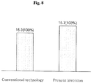
- FIG. 8 is a performance graph according to an embodiment of the present invention.
- the micro channel type heat exchanger according to the present embodiment can improve thermal exchange performance of about 3% compared to a conventional technology.
- a second embodiment of the present invention is described below with reference to FIG. 9 .
- a heat blocking member 120 according to the present embodiment is not located between headers, but connects the headers.
- the heat blocking members according to the first embodiment are inserted between the headers and fixed thereto.
- the heat blocking member 120 according to the present embodiment connects the outsides of the headers.
- the heat blocking member 120 connects the first and the second lower headers 70 and 71 or connects the first and the second upper headers 80 and 81.
- the heat blocking member 120 may be curved along the outside surfaces of the first and the second lower headers 70 and 71. In some embodiments, the heat blocking member 120 may be formed in a plate form.
- the heat blocking member 120 can be fixed to the first and the second lower headers 70 and 71.
- a heat blocking space 101 is formed between the first and the second lower headers 70 and 71.
- a heat blocking space 101 is also formed between the first and the second upper headers 80 and 81 (not shown).
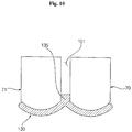
- a third embodiment of the present invention is described below with reference to FIG. 10 .
- a heat blocking member 130 according to the present embodiment is similar to that of the second embodiment, but further includes an insertion part 135 inserted between headers.
- the insertion part 135 is inserted between the first and the second lower headers 70 and 71 and fixed thereto.
- a heat blocking space 101 is secured by the insertion part 135.
- the insertion part 135 may support the first heat exchange module 30 and the second heat exchange module 40. Although an external impact is applied, the heat blocking space 101 is maintained by the insertion part 135.
- the heat blocking member 130 may be installed on the first and the second upper headers 80 and 81.
- the heat blocking member 130 may be installed on the first and the second lower headers 70 and 71.
- the heat exchanger of the present invention has the following one or more effects.
- an embodiment of the present invention can improve thermal exchange performance because the heat blocking member forming the heat blocking space is disposed between the first heat exchange module and the second heat exchange module and heat conductivity is minimized through the heat blocking member.
- an embodiment of the present invention can improve thermal exchange performance because the (3-1)-th pass disposed in the first heat exchange module and the (3-2)-th pass disposed in the second heat exchange module operate as a single pass.
- an embodiment of the present invention has an advantage in that it can control a ratio of flat tubes of the third pass to the number of all of flat tubes because the third pass is distributed and disposed in the two heat exchange modules.
- an embodiment of the present invention has an advantage in that it can reduce a pressure loss of a refrigerant if the heat exchanger is used as an evaporator because the number of flat tubes of each of the first pass, the second pass, and the third pass is gradually increased.
- an embodiment of the present invention has an advantage in that it can reduce a pressure loss generated when a refrigerant is evaporated because the third pass of the four passes is distributed and disposed in different heat exchange modules, but the distributed passes operate as a single pass.
Landscapes
- Engineering & Computer Science (AREA)
- Physics & Mathematics (AREA)
- Thermal Sciences (AREA)
- Mechanical Engineering (AREA)
- General Engineering & Computer Science (AREA)
- Geometry (AREA)
- Heat-Exchange Devices With Radiators And Conduit Assemblies (AREA)
Claims (9)
- Mikrokanal-Wärmetauscher, in dem ein erstes Wärmetauschmodul (30) und ein zweites Wärmetauschmodul (40) aufeinander gestapelt sind, wobei das erste Wärmetauschmodul (30) und das zweite Wärmetauschmodul (40) eine Vielzahl von flachen Röhren (50) aufweisen, wobei der Mikrokanal-Wärmetauscher aufweist:ein Wärmesperrelement (100, 105, 110, 115; 120; 130), das konfiguriert ist, durch Trennen des ersten Wärmetauschmoduls (30) und des zweiten Wärmetauschmoduls (40) einen Wärmesperrraum (101) zu bilden;einen ersten Durchgang (31), der in einigen der Vielzahl der flachen Röhren (50) angeordnet ist, die im ersten Wärmetauschmodul (30) angeordnet sind und längs derer ein Kältemittel in eine Richtung fließt;einen zweiten Durchgang (32), der in einigen restlichen der Vielzahl der flachen Röhren (50) angeordnet ist, die im ersten Wärmetauschmodul (30) angeordnet sind und längs derer das Kältemittel, das vom ersten Durchgang (31) zugeführt wird, in eine zu einer Richtung des ersten Durchgangs (31) entgegengesetzte Richtung fließt;einen dritten Durchgang (33), der in einem anderen Rest als der erste Durchgang (31) und zweite Durchgang (32) der Vielzahl der flachen Röhren (50), die im ersten Wärmetauschmodul (30) angeordnet sind, und in einigen einer Vielzahl der flachen Röhren (50) verteilt und angeordnet ist, die im zweiten Wärmetauschmodul (40) angeordnet sind; undeinen vierten Durchgang (34), der in einem Rest der Vielzahl der flachen Röhren (50) angeordnet ist, die im zweiten Wärmetauschmodul (40) angeordnet sind und längs derer ein Kältemittel, das vom dritten Durchgang (33) zugeführt wird, in eine zu einer Richtung des dritten Durchgangs (33) entgegengesetzte Richtung fließt,wobei der dritte Durchgang (33) einen (3-1)-ten Durchgang, der im anderen Rest als der erste Durchgang (31) und der zweite Durchgang (32) der Vielzahl der flachen Röhren (50) angeordnet ist, die im ersten Wärmetauschmodul (30) angeordnet sind und längs derer das Kältemittel, das vom zweiten Durchgang (32) zugeführt wird, in einer zur Richtung des zweiten Durchgangs (32) entgegengesetzte Richtung fließt, und einen (3-2)-ten Durchgang aufweist, der in einigen der Vielzahl der flachen Röhren (50) angeordnet ist, die im zweiten Wärmetauschmodul (40) angeordnet sind und längs derer das Kältemittel, das vom zweiten Durchgang (32) zugeführt wird, in die zur Richtung des zweiten Durchgangs (32) entgegengesetzte Richtung fließt und in eine zur Richtung des (3-1)-ten Durchgangs identische Richtung fließt,wobei das erste Wärmetauschmodul (30) aufweist: die Vielzahl der flachen Röhren (50), die konfiguriert sind, einen Kältemittelfluss längs der flachen Röhren (50) aufzuweisen; ein Rippe (60), die konfiguriert ist, die flachen Röhren (50) zu verbinden und Wärme zu leiten; einen ersten unteren Sammler (70), der mit einer ersten Seite der Vielzahl der flachen Röhren (50) verbunden und konfiguriert ist, mit der ersten Seite der Vielzahl der flachen Röhren (50) in Verbindung zu stehen, so dass das Kältemittel fließt; einen ersten oberen Sammler (80), der mit einer zweiten Seite der Vielzahl der flachen Röhren (50) verbunden und konfiguriert ist, mit der zweiten Seite der Vielzahl der flachen Röhren (50) in Verbindung zu stehen, so dass das Kältemittel fließt; eine erste Umlenkplatte (91), die im ersten unteren Sammler (70) angeordnet und konfiguriert ist, durch Unterteilen eines Inneren des ersten unteren Sammlers (70) den ersten Durchgang (31) und den zweiten Durchgang (32) zu bilden; und eine zweite Umlenkplatte, die im ersten oberen Sammler (80) angeordnet und konfiguriert ist, durch Unterteilen eines Inneren eines zweiten oberen Sammlers (81) den zweiten Durchgang (32) und den (3-1)-ten Durchgang zu bilden,wobei das zweite Wärmetauschmodul (40) aufweist: die Vielzahl der flachen Röhren (50), die konfiguriert sind, einen Kältemittelfluss in den flachen Röhren (50) aufzuweisen; eine Rippe (60), die konfiguriert ist, die flachen Röhren (50) zu verbinden und Wärme zu leiten; einen zweiten unteren Sammler (71), der mit einer ersten Seite der Vielzahl der flachen Röhren (50) verbunden und konfiguriert ist, mit der ersten Seite der Vielzahl der flachen Röhren (50) in Verbindung zu stehen, so dass ein Kältemittel fließt; den zweiten oberen Sammler (81), der mit einer zweiten Seite der Vielzahl der flachen Röhren (50) verbunden und konfiguriert ist, mit der zweiten Seite der Vielzahl der flachen Röhren (50) in Verbindung zu stehen, so dass das Kältemittel fließt; und eine dritte Umlenkplatte, die im zweiten unteren Sammler (71) angeordnet und konfiguriert ist, durch Unterteilen des zweiten unteren Sammlers (71) den (3-2)-ten Durchgang und den vierten Durchgang (34) zu bilden,wobei das Wärmesperrelement zwischen dem ersten oberen Sammler (80) und dem zweiten oberen Sammler (81) oder zwischen dem ersten unteren Sammler (70) und dem zweiten unteren Sammler (71) oder beiden angeordnet ist,wobei ein erster Trennraum (61) zwischen dem ersten Durchgang (31) und dem zweiten Durchgang (32) ausgebildet ist, ein zweiter Trennraum (62) zwischen dem zweiten Durchgang (32) und dem (3-1)-ten Durchgang ausgebildet ist und ein dritter Trennraum (63) zwischen dem (3-2)-ten Durchgang und dem vierten Durchgang (34) ausgebildet ist, undwobei der erste Trennraum (61), der zweite Trennraum (62) und der dritte Trennraum (63) konfiguriert sind, zu verhindern, dass Wärme an einen benachbarten Durchgang abgegeben wird.
- Mikrokanal-Wärmetauscher nach Anspruch 1, wobei das Wärmesperrelement (130) ferner ein Einsatzteil (135) aufweist, das zwischen dem ersten Wärmetauschmodul (30) und dem zweiten Wärmetauschmodul (40) eingesetzt und konfiguriert ist, das erste Wärmetauschmodul (30) und das zweite Wärmetauschmodul (40) zu halten.
- Mikrokanal-Wärmetauscher nach Anspruch 1 oder 2, wobei:ein erstes oberes Loch (85-1) im ersten oberen Sammler (80) ausgebildet ist, in dem der (3-1)-te Durchgang ausgebildet worden ist,ein zweites oberes Loch (85-2) im zweiten oberen Sammler (81) ausgebildet ist, in dem der (3-2)-te Durchgang ausgebildet worden ist,etwas des Kältemittels des dritten Durchgangs (33) im zweiten oberen Sammler (81) durch das erste obere Loch (85-1) und das zweite obere Loch (85-2) fließt, unddas Wärmesperrelement (100, 110) zwischen dem ersten oberen Loch (85-1) und dem zweiten oberen Loch (85-2) angeordnet ist.
- Mikrokanal-Wärmetauscher nach Anspruch 3, wobei das Wärmesperrelement (100) ein erstes Plattenloch (185) aufweist, das konfiguriert ist, das erste obere Loch (85-1) und das zweite obere Loch (85-2) zu verbinden, so dass das Kältemittel fließt.
- Mikrokanal-Wärmetauscher nach Anspruch 1 oder 2, wobei:ein erstes unteres Loch (75-1) im ersten unteren Sammler (70) ausgebildet ist, in dem der (3-1)-te Durchgang ausgebildet worden ist,ein zweites unteres Loch (75-2) im zweiten unteren Sammler (71) ausgebildet ist, in dem der (3-2)-te Durchgang ausgebildet worden ist,etwas des Kältemittels des dritten Durchgangs (33) im zweiten unteren Sammler (71) durch das erste untere Loch (75-1) und das zweite untere Loch (75-2) fließt, unddas Wärmesperrelement (105, 115) zwischen dem ersten unteren Loch (75-1) und dem zweiten unteren Loch (75-2) angeordnet ist.
- Mikrokanal-Wärmetauscher nach Anspruch 5, wobei das Wärmesperrelement (105) ein zweites Plattenloch (175) aufweist, das konfiguriert ist, das erste untere Loch (75-1) und das zweite untere Loch (75-2) zu verbinden, so dass das Kältemittel fließt.
- Mikrokanal-Wärmetauscher nach Anspruch 1 oder 2, wobei:ein erstes oberes Loch (85-1) im ersten oberen Sammler (80) ausgebildet ist, in dem der (3-1)-te Durchgang ausgebildet worden ist, ein zweites oberes Loch (85-2) im zweiten oberen Sammler (81) ausgebildet ist, in dem der (3-2)-ten Durchgang ausgebildet worden ist, und etwas des Kältemittels des dritten Durchgangs (33) im zweiten oberen Sammler (81) durch das erste obere Loch (85-1) und das zweite obere Loch (85-2) fließt,ein erstes unteres Loch (75-1) im ersten unteren Sammler (70) ausgebildet ist, in dem der (3-1)-te Durchgang ausgebildet worden ist, ein zweites unteres Loch (75-2) im zweiten unteren Sammler (71) ausgebildet ist, in dem der (3-2)-te Durchgang ausgebildet worden ist, und ein Rest des Kältemittels des dritten Durchgangs (33) im zweiten unteren Sammler (71) durch das erste untere Loch (75-1) und das zweite untere Loch (75-2) fließt, unddas Wärmesperrelement ein erstes Wärmesperrelement (100), das zwischen dem ersten oberen Loch (85-1) und dem zweiten oberen Loch (85-2) angeordnet ist, und ein zweites Wärmesperrelement (105) aufweist, das zwischen dem ersten unteren Loch (75-1) und dem zweiten unteren Loch (75-2) angeordnet ist.
- Mikrokanal-Wärmetauscher nach Anspruch 7, wobei:das erste Wärmesperrelement (100) ferner ein erstes Plattenloch (185) aufweist, das konfiguriert ist, das erste obere Loch (85-1) und das zweite obere Loch (85-2) zu verbinden, unddas zweite Wärmesperrelement (105) ferner ein zweites Plattenloch (175) aufweist, das konfiguriert ist, das erste untere Loch (75-1) und das zweite untere Loch (75-2) zu verbinden.
- Mikrokanal-Wärmetauscher nach Anspruch 1, wobei:die erste Umlenkplatte (91) über oder unter dem ersten Trennraum (61) angeordnet ist,die zweite Umlenkplatte (92) über oder unter dem zweiten Trennraum (62) angeordnet ist und die dritte Umlenkplatte (93) über oder unter dem dritten Trennraum (63) angeordnet ist.
Applications Claiming Priority (1)
| Application Number | Priority Date | Filing Date | Title |
|---|---|---|---|
| KR1020150129285A KR20170031556A (ko) | 2015-09-11 | 2015-09-11 | 마이크로 채널 타입 열교환기 |
Publications (2)
| Publication Number | Publication Date |
|---|---|
| EP3141859A1 EP3141859A1 (de) | 2017-03-15 |
| EP3141859B1 true EP3141859B1 (de) | 2018-05-16 |
Family
ID=56893861
Family Applications (1)
| Application Number | Title | Priority Date | Filing Date |
|---|---|---|---|
| EP16188061.2A Not-in-force EP3141859B1 (de) | 2015-09-11 | 2016-09-09 | Mikrokanalwärmetauscher |
Country Status (3)
| Country | Link |
|---|---|
| US (1) | US11280551B2 (de) |
| EP (1) | EP3141859B1 (de) |
| KR (1) | KR20170031556A (de) |
Families Citing this family (8)
| Publication number | Priority date | Publication date | Assignee | Title |
|---|---|---|---|---|
| KR101837046B1 (ko) * | 2015-07-31 | 2018-04-19 | 엘지전자 주식회사 | 열교환기 |
| US20190162455A1 (en) * | 2017-11-29 | 2019-05-30 | Lennox Industries, Inc. | Microchannel heat exchanger |
| EP3980709A4 (de) * | 2019-06-04 | 2023-01-25 | Pranav Vikas India PVT Limited | Ccf-heizkernanordnung |
| US11765864B2 (en) | 2019-08-26 | 2023-09-19 | Ovh | Cooling arrangement for a rack hosting electronic equipment and at least one fan |
| WO2022201514A1 (ja) * | 2021-03-26 | 2022-09-29 | 三菱電機株式会社 | 空気調和装置 |
| US11737246B2 (en) * | 2021-04-27 | 2023-08-22 | Quanta Computer Inc. | Dual-radiator cooling device |
| JP7744884B2 (ja) * | 2022-07-26 | 2025-09-26 | ハイリマレリジャパン株式会社 | 熱交換器 |
| WO2025100999A1 (ko) * | 2023-11-10 | 2025-05-15 | 엘지이노텍 주식회사 | 열전소자를 포함하는 열교환장치 |
Family Cites Families (14)
| Publication number | Priority date | Publication date | Assignee | Title |
|---|---|---|---|---|
| JP3030036B2 (ja) * | 1989-08-23 | 2000-04-10 | 昭和アルミニウム株式会社 | 複式熱交換器 |
| JPH11142087A (ja) | 1997-11-13 | 1999-05-28 | Showa Alum Corp | 熱交換器 |
| JP2004144395A (ja) * | 2002-10-24 | 2004-05-20 | Denso Corp | 冷媒蒸発器 |
| JP2004183960A (ja) * | 2002-12-02 | 2004-07-02 | Nikkei Nekko Kk | 熱交換器 |
| DE102005058769B4 (de) * | 2005-12-09 | 2016-11-03 | Modine Manufacturing Co. | Ladeluftkühler |
| KR100765557B1 (ko) | 2005-12-31 | 2007-10-09 | 엘지전자 주식회사 | 열교환기 |
| US8464782B2 (en) * | 2009-10-20 | 2013-06-18 | Delphi Technologies, Inc. | Manifold fluid communication plate |
| JP2013134016A (ja) | 2011-12-27 | 2013-07-08 | Daikin Industries Ltd | 熱交換器 |
| JP5875918B2 (ja) * | 2012-03-27 | 2016-03-02 | サンデンホールディングス株式会社 | 車室内熱交換器及び車室内熱交換器のヘッダ間接続部材 |
| JP6216113B2 (ja) * | 2012-04-02 | 2017-10-18 | サンデンホールディングス株式会社 | 熱交換器及びそれを用いたヒートポンプシステム |
| KR101826365B1 (ko) | 2012-05-04 | 2018-03-22 | 엘지전자 주식회사 | 열교환기 |
| JP6111024B2 (ja) * | 2012-06-19 | 2017-04-05 | サンデンホールディングス株式会社 | 熱交換器 |
| JP6088905B2 (ja) | 2013-05-24 | 2017-03-01 | サンデンホールディングス株式会社 | 複式熱交換器 |
| KR102170312B1 (ko) * | 2014-02-07 | 2020-10-26 | 엘지전자 주식회사 | 열교환기 |
-
2015
- 2015-09-11 KR KR1020150129285A patent/KR20170031556A/ko not_active Ceased
-
2016
- 2016-09-09 US US15/260,914 patent/US11280551B2/en active Active
- 2016-09-09 EP EP16188061.2A patent/EP3141859B1/de not_active Not-in-force
Non-Patent Citations (1)
| Title |
|---|
| None * |
Also Published As
| Publication number | Publication date |
|---|---|
| KR20170031556A (ko) | 2017-03-21 |
| US20170074591A1 (en) | 2017-03-16 |
| EP3141859A1 (de) | 2017-03-15 |
| US11280551B2 (en) | 2022-03-22 |
Similar Documents
| Publication | Publication Date | Title |
|---|---|---|
| EP3141859B1 (de) | Mikrokanalwärmetauscher | |
| US9651317B2 (en) | Heat exchanger and air conditioner | |
| EP2447657B1 (de) | Mehrzonen-Wärmetauscher mit unterteilten Sammelrohren | |
| US10041710B2 (en) | Heat exchanger and air conditioner | |
| KR20160131577A (ko) | 공기조화기의 열교환기 | |
| CN102455087B (zh) | 集管单元和具有该集管单元的热交换器 | |
| US20150021003A1 (en) | Heat exchanger | |
| EP3290851B1 (de) | Geschichtetes kopfteil, wärmetauscher und klimaanlage | |
| KR20170079223A (ko) | 일체형 수냉식 응축기 | |
| JP4358981B2 (ja) | 空調用凝縮器 | |
| EP3473963A1 (de) | Wärmetauscher und klimaanlage | |
| KR20130084178A (ko) | 헤더 유닛 및 이를 가지는 열교환기 | |
| KR101837046B1 (ko) | 열교환기 | |
| EP3139122B1 (de) | Mikrokanal-wärmetauscher | |
| KR20130084179A (ko) | 열교환기 | |
| JP6939869B2 (ja) | 熱交換器 | |
| JP2024045455A (ja) | 熱交換器および冷凍サイクル装置 | |
| JP7209821B2 (ja) | 熱交換器及び冷凍サイクル装置 | |
| CN121039455A (zh) | 热交换器以及空气调节装置 | |
| WO2023195040A1 (ja) | 熱交換器、および空気調和機の室外機 | |
| KR20240095873A (ko) | 열교환기 | |
| KR20170034163A (ko) | 마이크로 채널 타입 열교환기 | |
| KR20190142855A (ko) | 응축기 |
Legal Events
| Date | Code | Title | Description |
|---|---|---|---|
| PUAI | Public reference made under article 153(3) epc to a published international application that has entered the european phase |
Free format text: ORIGINAL CODE: 0009012 |
|
| 17P | Request for examination filed |
Effective date: 20161010 |
|
| AK | Designated contracting states |
Kind code of ref document: A1 Designated state(s): AL AT BE BG CH CY CZ DE DK EE ES FI FR GB GR HR HU IE IS IT LI LT LU LV MC MK MT NL NO PL PT RO RS SE SI SK SM TR |
|
| AX | Request for extension of the european patent |
Extension state: BA ME |
|
| RBV | Designated contracting states (corrected) |
Designated state(s): AL AT BE BG CH CY CZ DE DK EE ES FI FR GB GR HR HU IE IS IT LI LT LU LV MC MK MT NL NO PL PT RO RS SE SI SK SM TR |
|
| RIC1 | Information provided on ipc code assigned before grant |
Ipc: F28F 1/12 20060101ALI20171026BHEP Ipc: F28D 1/04 20060101ALI20171026BHEP Ipc: F28D 21/00 20060101ALI20171026BHEP Ipc: F28F 9/02 20060101ALI20171026BHEP Ipc: F28D 1/053 20060101AFI20171026BHEP |
|
| GRAP | Despatch of communication of intention to grant a patent |
Free format text: ORIGINAL CODE: EPIDOSNIGR1 |
|
| INTG | Intention to grant announced |
Effective date: 20171201 |
|
| GRAS | Grant fee paid |
Free format text: ORIGINAL CODE: EPIDOSNIGR3 |
|
| GRAA | (expected) grant |
Free format text: ORIGINAL CODE: 0009210 |
|
| AK | Designated contracting states |
Kind code of ref document: B1 Designated state(s): AL AT BE BG CH CY CZ DE DK EE ES FI FR GB GR HR HU IE IS IT LI LT LU LV MC MK MT NL NO PL PT RO RS SE SI SK SM TR |
|
| REG | Reference to a national code |
Ref country code: GB Ref legal event code: FG4D |
|
| REG | Reference to a national code |
Ref country code: CH Ref legal event code: EP |
|
| REG | Reference to a national code |
Ref country code: IE Ref legal event code: FG4D |
|
| REG | Reference to a national code |
Ref country code: DE Ref legal event code: R096 Ref document number: 602016003103 Country of ref document: DE |
|
| REG | Reference to a national code |
Ref country code: AT Ref legal event code: REF Ref document number: 999963 Country of ref document: AT Kind code of ref document: T Effective date: 20180615 |
|
| REG | Reference to a national code |
Ref country code: NL Ref legal event code: MP Effective date: 20180516 |
|
| REG | Reference to a national code |
Ref country code: LT Ref legal event code: MG4D |
|
| PG25 | Lapsed in a contracting state [announced via postgrant information from national office to epo] |
Ref country code: ES Free format text: LAPSE BECAUSE OF FAILURE TO SUBMIT A TRANSLATION OF THE DESCRIPTION OR TO PAY THE FEE WITHIN THE PRESCRIBED TIME-LIMIT Effective date: 20180516 Ref country code: SE Free format text: LAPSE BECAUSE OF FAILURE TO SUBMIT A TRANSLATION OF THE DESCRIPTION OR TO PAY THE FEE WITHIN THE PRESCRIBED TIME-LIMIT Effective date: 20180516 Ref country code: BG Free format text: LAPSE BECAUSE OF FAILURE TO SUBMIT A TRANSLATION OF THE DESCRIPTION OR TO PAY THE FEE WITHIN THE PRESCRIBED TIME-LIMIT Effective date: 20180816 Ref country code: NO Free format text: LAPSE BECAUSE OF FAILURE TO SUBMIT A TRANSLATION OF THE DESCRIPTION OR TO PAY THE FEE WITHIN THE PRESCRIBED TIME-LIMIT Effective date: 20180816 Ref country code: FI Free format text: LAPSE BECAUSE OF FAILURE TO SUBMIT A TRANSLATION OF THE DESCRIPTION OR TO PAY THE FEE WITHIN THE PRESCRIBED TIME-LIMIT Effective date: 20180516 Ref country code: LT Free format text: LAPSE BECAUSE OF FAILURE TO SUBMIT A TRANSLATION OF THE DESCRIPTION OR TO PAY THE FEE WITHIN THE PRESCRIBED TIME-LIMIT Effective date: 20180516 |
|
| PG25 | Lapsed in a contracting state [announced via postgrant information from national office to epo] |
Ref country code: GR Free format text: LAPSE BECAUSE OF FAILURE TO SUBMIT A TRANSLATION OF THE DESCRIPTION OR TO PAY THE FEE WITHIN THE PRESCRIBED TIME-LIMIT Effective date: 20180817 Ref country code: HR Free format text: LAPSE BECAUSE OF FAILURE TO SUBMIT A TRANSLATION OF THE DESCRIPTION OR TO PAY THE FEE WITHIN THE PRESCRIBED TIME-LIMIT Effective date: 20180516 Ref country code: NL Free format text: LAPSE BECAUSE OF FAILURE TO SUBMIT A TRANSLATION OF THE DESCRIPTION OR TO PAY THE FEE WITHIN THE PRESCRIBED TIME-LIMIT Effective date: 20180516 Ref country code: LV Free format text: LAPSE BECAUSE OF FAILURE TO SUBMIT A TRANSLATION OF THE DESCRIPTION OR TO PAY THE FEE WITHIN THE PRESCRIBED TIME-LIMIT Effective date: 20180516 Ref country code: RS Free format text: LAPSE BECAUSE OF FAILURE TO SUBMIT A TRANSLATION OF THE DESCRIPTION OR TO PAY THE FEE WITHIN THE PRESCRIBED TIME-LIMIT Effective date: 20180516 |
|
| REG | Reference to a national code |
Ref country code: AT Ref legal event code: MK05 Ref document number: 999963 Country of ref document: AT Kind code of ref document: T Effective date: 20180516 |
|
| PG25 | Lapsed in a contracting state [announced via postgrant information from national office to epo] |
Ref country code: CZ Free format text: LAPSE BECAUSE OF FAILURE TO SUBMIT A TRANSLATION OF THE DESCRIPTION OR TO PAY THE FEE WITHIN THE PRESCRIBED TIME-LIMIT Effective date: 20180516 Ref country code: RO Free format text: LAPSE BECAUSE OF FAILURE TO SUBMIT A TRANSLATION OF THE DESCRIPTION OR TO PAY THE FEE WITHIN THE PRESCRIBED TIME-LIMIT Effective date: 20180516 Ref country code: EE Free format text: LAPSE BECAUSE OF FAILURE TO SUBMIT A TRANSLATION OF THE DESCRIPTION OR TO PAY THE FEE WITHIN THE PRESCRIBED TIME-LIMIT Effective date: 20180516 Ref country code: AT Free format text: LAPSE BECAUSE OF FAILURE TO SUBMIT A TRANSLATION OF THE DESCRIPTION OR TO PAY THE FEE WITHIN THE PRESCRIBED TIME-LIMIT Effective date: 20180516 Ref country code: DK Free format text: LAPSE BECAUSE OF FAILURE TO SUBMIT A TRANSLATION OF THE DESCRIPTION OR TO PAY THE FEE WITHIN THE PRESCRIBED TIME-LIMIT Effective date: 20180516 Ref country code: PL Free format text: LAPSE BECAUSE OF FAILURE TO SUBMIT A TRANSLATION OF THE DESCRIPTION OR TO PAY THE FEE WITHIN THE PRESCRIBED TIME-LIMIT Effective date: 20180516 Ref country code: SK Free format text: LAPSE BECAUSE OF FAILURE TO SUBMIT A TRANSLATION OF THE DESCRIPTION OR TO PAY THE FEE WITHIN THE PRESCRIBED TIME-LIMIT Effective date: 20180516 |
|
| REG | Reference to a national code |
Ref country code: DE Ref legal event code: R097 Ref document number: 602016003103 Country of ref document: DE |
|
| PG25 | Lapsed in a contracting state [announced via postgrant information from national office to epo] |
Ref country code: IT Free format text: LAPSE BECAUSE OF FAILURE TO SUBMIT A TRANSLATION OF THE DESCRIPTION OR TO PAY THE FEE WITHIN THE PRESCRIBED TIME-LIMIT Effective date: 20180516 Ref country code: SM Free format text: LAPSE BECAUSE OF FAILURE TO SUBMIT A TRANSLATION OF THE DESCRIPTION OR TO PAY THE FEE WITHIN THE PRESCRIBED TIME-LIMIT Effective date: 20180516 |
|
| PLBE | No opposition filed within time limit |
Free format text: ORIGINAL CODE: 0009261 |
|
| STAA | Information on the status of an ep patent application or granted ep patent |
Free format text: STATUS: NO OPPOSITION FILED WITHIN TIME LIMIT |
|
| 26N | No opposition filed |
Effective date: 20190219 |
|
| PG25 | Lapsed in a contracting state [announced via postgrant information from national office to epo] |
Ref country code: MC Free format text: LAPSE BECAUSE OF FAILURE TO SUBMIT A TRANSLATION OF THE DESCRIPTION OR TO PAY THE FEE WITHIN THE PRESCRIBED TIME-LIMIT Effective date: 20180516 |
|
| PG25 | Lapsed in a contracting state [announced via postgrant information from national office to epo] |
Ref country code: SI Free format text: LAPSE BECAUSE OF FAILURE TO SUBMIT A TRANSLATION OF THE DESCRIPTION OR TO PAY THE FEE WITHIN THE PRESCRIBED TIME-LIMIT Effective date: 20180516 |
|
| REG | Reference to a national code |
Ref country code: BE Ref legal event code: MM Effective date: 20180930 |
|
| REG | Reference to a national code |
Ref country code: IE Ref legal event code: MM4A |
|
| PG25 | Lapsed in a contracting state [announced via postgrant information from national office to epo] |
Ref country code: LU Free format text: LAPSE BECAUSE OF NON-PAYMENT OF DUE FEES Effective date: 20180909 |
|
| PG25 | Lapsed in a contracting state [announced via postgrant information from national office to epo] |
Ref country code: IE Free format text: LAPSE BECAUSE OF NON-PAYMENT OF DUE FEES Effective date: 20180909 |
|
| PG25 | Lapsed in a contracting state [announced via postgrant information from national office to epo] |
Ref country code: FR Free format text: LAPSE BECAUSE OF NON-PAYMENT OF DUE FEES Effective date: 20180930 Ref country code: BE Free format text: LAPSE BECAUSE OF NON-PAYMENT OF DUE FEES Effective date: 20180930 |
|
| PG25 | Lapsed in a contracting state [announced via postgrant information from national office to epo] |
Ref country code: AL Free format text: LAPSE BECAUSE OF FAILURE TO SUBMIT A TRANSLATION OF THE DESCRIPTION OR TO PAY THE FEE WITHIN THE PRESCRIBED TIME-LIMIT Effective date: 20180516 |
|
| PG25 | Lapsed in a contracting state [announced via postgrant information from national office to epo] |
Ref country code: MT Free format text: LAPSE BECAUSE OF NON-PAYMENT OF DUE FEES Effective date: 20180909 |
|
| PG25 | Lapsed in a contracting state [announced via postgrant information from national office to epo] |
Ref country code: TR Free format text: LAPSE BECAUSE OF FAILURE TO SUBMIT A TRANSLATION OF THE DESCRIPTION OR TO PAY THE FEE WITHIN THE PRESCRIBED TIME-LIMIT Effective date: 20180516 |
|
| PG25 | Lapsed in a contracting state [announced via postgrant information from national office to epo] |
Ref country code: PT Free format text: LAPSE BECAUSE OF FAILURE TO SUBMIT A TRANSLATION OF THE DESCRIPTION OR TO PAY THE FEE WITHIN THE PRESCRIBED TIME-LIMIT Effective date: 20180516 |
|
| REG | Reference to a national code |
Ref country code: CH Ref legal event code: PL |
|
| PG25 | Lapsed in a contracting state [announced via postgrant information from national office to epo] |
Ref country code: HU Free format text: LAPSE BECAUSE OF FAILURE TO SUBMIT A TRANSLATION OF THE DESCRIPTION OR TO PAY THE FEE WITHIN THE PRESCRIBED TIME-LIMIT; INVALID AB INITIO Effective date: 20160909 Ref country code: CY Free format text: LAPSE BECAUSE OF FAILURE TO SUBMIT A TRANSLATION OF THE DESCRIPTION OR TO PAY THE FEE WITHIN THE PRESCRIBED TIME-LIMIT Effective date: 20180516 Ref country code: MK Free format text: LAPSE BECAUSE OF NON-PAYMENT OF DUE FEES Effective date: 20180516 |
|
| PG25 | Lapsed in a contracting state [announced via postgrant information from national office to epo] |
Ref country code: CH Free format text: LAPSE BECAUSE OF NON-PAYMENT OF DUE FEES Effective date: 20190930 Ref country code: LI Free format text: LAPSE BECAUSE OF NON-PAYMENT OF DUE FEES Effective date: 20190930 Ref country code: IS Free format text: LAPSE BECAUSE OF FAILURE TO SUBMIT A TRANSLATION OF THE DESCRIPTION OR TO PAY THE FEE WITHIN THE PRESCRIBED TIME-LIMIT Effective date: 20180916 |
|
| GBPC | Gb: european patent ceased through non-payment of renewal fee |
Effective date: 20200909 |
|
| PG25 | Lapsed in a contracting state [announced via postgrant information from national office to epo] |
Ref country code: GB Free format text: LAPSE BECAUSE OF NON-PAYMENT OF DUE FEES Effective date: 20200909 |
|
| PGFP | Annual fee paid to national office [announced via postgrant information from national office to epo] |
Ref country code: DE Payment date: 20230807 Year of fee payment: 8 |
|
| REG | Reference to a national code |
Ref country code: DE Ref legal event code: R119 Ref document number: 602016003103 Country of ref document: DE |
|
| PG25 | Lapsed in a contracting state [announced via postgrant information from national office to epo] |
Ref country code: DE Free format text: LAPSE BECAUSE OF NON-PAYMENT OF DUE FEES Effective date: 20250401 |