EP3141880A1 - Mesure de fibre avec mise en forme d'impulsion - Google Patents
Mesure de fibre avec mise en forme d'impulsion Download PDFInfo
- Publication number
- EP3141880A1 EP3141880A1 EP16184410.5A EP16184410A EP3141880A1 EP 3141880 A1 EP3141880 A1 EP 3141880A1 EP 16184410 A EP16184410 A EP 16184410A EP 3141880 A1 EP3141880 A1 EP 3141880A1
- Authority
- EP
- European Patent Office
- Prior art keywords
- pulse
- electromagnetic radiation
- shape
- fiber
- deviation
- Prior art date
- Legal status (The legal status is an assumption and is not a legal conclusion. Google has not performed a legal analysis and makes no representation as to the accuracy of the status listed.)
- Granted
Links
Images

Classifications
-
- G—PHYSICS
- G01—MEASURING; TESTING
- G01D—MEASURING NOT SPECIALLY ADAPTED FOR A SPECIFIC VARIABLE; ARRANGEMENTS FOR MEASURING TWO OR MORE VARIABLES NOT COVERED IN A SINGLE OTHER SUBCLASS; TARIFF METERING APPARATUS; MEASURING OR TESTING NOT OTHERWISE PROVIDED FOR
- G01D5/00—Mechanical means for transferring the output of a sensing member; Means for converting the output of a sensing member to another variable where the form or nature of the sensing member does not constrain the means for converting; Transducers not specially adapted for a specific variable
- G01D5/26—Mechanical means for transferring the output of a sensing member; Means for converting the output of a sensing member to another variable where the form or nature of the sensing member does not constrain the means for converting; Transducers not specially adapted for a specific variable characterised by optical transfer means, i.e. using infrared, visible, or ultraviolet light
- G01D5/268—Mechanical means for transferring the output of a sensing member; Means for converting the output of a sensing member to another variable where the form or nature of the sensing member does not constrain the means for converting; Transducers not specially adapted for a specific variable characterised by optical transfer means, i.e. using infrared, visible, or ultraviolet light using optical fibres
-
- G—PHYSICS
- G01—MEASURING; TESTING
- G01M—TESTING STATIC OR DYNAMIC BALANCE OF MACHINES OR STRUCTURES; TESTING OF STRUCTURES OR APPARATUS, NOT OTHERWISE PROVIDED FOR
- G01M11/00—Testing of optical apparatus; Testing structures by optical methods not otherwise provided for
- G01M11/30—Testing of optical devices, constituted by fibre optics or optical waveguides
- G01M11/31—Testing of optical devices, constituted by fibre optics or optical waveguides with a light emitter and a light receiver being disposed at the same side of a fibre or waveguide end-face, e.g. reflectometers
- G01M11/3109—Reflectometers detecting the back-scattered light in the time-domain, e.g. OTDR
- G01M11/3145—Details of the optoelectronics or data analysis
-
- G—PHYSICS
- G01—MEASURING; TESTING
- G01D—MEASURING NOT SPECIALLY ADAPTED FOR A SPECIFIC VARIABLE; ARRANGEMENTS FOR MEASURING TWO OR MORE VARIABLES NOT COVERED IN A SINGLE OTHER SUBCLASS; TARIFF METERING APPARATUS; MEASURING OR TESTING NOT OTHERWISE PROVIDED FOR
- G01D5/00—Mechanical means for transferring the output of a sensing member; Means for converting the output of a sensing member to another variable where the form or nature of the sensing member does not constrain the means for converting; Transducers not specially adapted for a specific variable
- G01D5/26—Mechanical means for transferring the output of a sensing member; Means for converting the output of a sensing member to another variable where the form or nature of the sensing member does not constrain the means for converting; Transducers not specially adapted for a specific variable characterised by optical transfer means, i.e. using infrared, visible, or ultraviolet light
- G01D5/32—Mechanical means for transferring the output of a sensing member; Means for converting the output of a sensing member to another variable where the form or nature of the sensing member does not constrain the means for converting; Transducers not specially adapted for a specific variable characterised by optical transfer means, i.e. using infrared, visible, or ultraviolet light with attenuation or whole or partial obturation of beams of light
- G01D5/34—Mechanical means for transferring the output of a sensing member; Means for converting the output of a sensing member to another variable where the form or nature of the sensing member does not constrain the means for converting; Transducers not specially adapted for a specific variable characterised by optical transfer means, i.e. using infrared, visible, or ultraviolet light with attenuation or whole or partial obturation of beams of light the beams of light being detected by photocells
- G01D5/353—Mechanical means for transferring the output of a sensing member; Means for converting the output of a sensing member to another variable where the form or nature of the sensing member does not constrain the means for converting; Transducers not specially adapted for a specific variable characterised by optical transfer means, i.e. using infrared, visible, or ultraviolet light with attenuation or whole or partial obturation of beams of light the beams of light being detected by photocells influencing the transmission properties of an optical fibre
- G01D5/35338—Mechanical means for transferring the output of a sensing member; Means for converting the output of a sensing member to another variable where the form or nature of the sensing member does not constrain the means for converting; Transducers not specially adapted for a specific variable characterised by optical transfer means, i.e. using infrared, visible, or ultraviolet light with attenuation or whole or partial obturation of beams of light the beams of light being detected by photocells influencing the transmission properties of an optical fibre using other arrangements than interferometer arrangements
- G01D5/35354—Sensor working in reflection
- G01D5/35358—Sensor working in reflection using backscattering to detect the measured quantity
-
- G—PHYSICS
- G01—MEASURING; TESTING
- G01K—MEASURING TEMPERATURE; MEASURING QUANTITY OF HEAT; THERMALLY-SENSITIVE ELEMENTS NOT OTHERWISE PROVIDED FOR
- G01K11/00—Measuring temperature based upon physical or chemical changes not covered by groups G01K3/00, G01K5/00, G01K7/00 or G01K9/00
- G01K11/32—Measuring temperature based upon physical or chemical changes not covered by groups G01K3/00, G01K5/00, G01K7/00 or G01K9/00 using changes in transmittance, scattering or luminescence in optical fibres
-
- G—PHYSICS
- G01—MEASURING; TESTING
- G01L—MEASURING FORCE, STRESS, TORQUE, WORK, MECHANICAL POWER, MECHANICAL EFFICIENCY, OR FLUID PRESSURE
- G01L1/00—Measuring force or stress, in general
- G01L1/24—Measuring force or stress, in general by measuring variations of optical properties of material when it is stressed, e.g. by photoelastic stress analysis using infrared, visible light, ultraviolet
- G01L1/242—Measuring force or stress, in general by measuring variations of optical properties of material when it is stressed, e.g. by photoelastic stress analysis using infrared, visible light, ultraviolet the material being an optical fibre
-
- G—PHYSICS
- G01—MEASURING; TESTING
- G01L—MEASURING FORCE, STRESS, TORQUE, WORK, MECHANICAL POWER, MECHANICAL EFFICIENCY, OR FLUID PRESSURE
- G01L1/00—Measuring force or stress, in general
- G01L1/24—Measuring force or stress, in general by measuring variations of optical properties of material when it is stressed, e.g. by photoelastic stress analysis using infrared, visible light, ultraviolet
- G01L1/247—Measuring force or stress, in general by measuring variations of optical properties of material when it is stressed, e.g. by photoelastic stress analysis using infrared, visible light, ultraviolet using distributed sensing elements, e.g. microcapsules
-
- G—PHYSICS
- G01—MEASURING; TESTING
- G01M—TESTING STATIC OR DYNAMIC BALANCE OF MACHINES OR STRUCTURES; TESTING OF STRUCTURES OR APPARATUS, NOT OTHERWISE PROVIDED FOR
- G01M11/00—Testing of optical apparatus; Testing structures by optical methods not otherwise provided for
- G01M11/30—Testing of optical devices, constituted by fibre optics or optical waveguides
- G01M11/31—Testing of optical devices, constituted by fibre optics or optical waveguides with a light emitter and a light receiver being disposed at the same side of a fibre or waveguide end-face, e.g. reflectometers
- G01M11/3109—Reflectometers detecting the back-scattered light in the time-domain, e.g. OTDR
- G01M11/3118—Reflectometers detecting the back-scattered light in the time-domain, e.g. OTDR using coded light-pulse sequences
Definitions
- the invention relates to a fiber measurement device, to a fiber measurement method, to a program element, and to a computer-readable medium.
- DTS devices are optoelectronic devices which measure temperature by optical fibers functioning as linear sensors. Temperature values are recorded along the optical sensor cable as a continuous profile. A high accuracy of temperature determination is achieved over long distances. Measurement distances of several kilometers can be achieved. The temperature dependence of the Raman effect can be used for a DTS measurement.
- a fiber under test can be probed by sending single pulses or sequences of pulses or pulse trains of light into the fiber.
- Backscattered light can be analyzed and spatially resolved for different physical properties of the fiber. For instance, Raman-backscatter gives information on temperature, Brillouin-scattered light contains information on temperature and strain and Rayleigh scattered light can be analyzed for losses and reflective sections of the fiber (OTDR) or be used for distributed acoustic sensing (C-OTDR).
- OTDR optical acoustic sensing
- the outgoing pulse has to generate backscatter at a limited spatial region for a distinct time, this requires production of short pulses. If the returning signal is resolved temporally, it is possible to obtain a distributed measurement signal over time.
- An approach that increases signal-to-noise ratio without increasing peak light power and without affecting the spatial resolution of the acquired signal is sending pulse trains which represent a code with suitable properties, as an example but not limited to Golay codes, Barker codes, or simplex codes.
- Artefacts in pulse generation may result in artefacts in measurement data.
- EP 2,775,278 discloses an optical fiber temperature distribution measurement device for measuring a temperature distribution along a longitudinal direction of an optical fiber.
- the device includes a light transmitter configured to input a train of code-modulated light pulses into the optical fiber, a light receiver configured to receive Raman back scattering light generated by inputting the train of code-modulated light pulses into the optical fiber, a demodulator configured to perform a correlation processing between a measured signal output from the light receiver and a code string associated with a type of the code modulation performed by the light transmitter, and to demodulate the measured signal.
- a storage is provided for storing correction data to be used to correct a distortion of the measured signal output from the light receiver when an impulsive pulsed light is output from the light transmitter.
- a corrector is configured to perform a correction to one of the measured signal output from the light receiver and a demodulated signal output from the demodulator, using the correction data stored in the storage.
- a fiber measurement device for measuring a physical quantity (in particular a value of a physical parameter, such as a temperature or a spatial temperature distribution) by a fiber
- the device comprises an electromagnetic radiation source configured for generating at least one pulse of electromagnetic radiation (such as visible light, infrared light and/or ultraviolet light) as primary electromagnetic radiation to be coupled into the fiber, and an adjustment unit (for instance a processor or part thereof) configured for, prior to, during or after the generating, adjusting (or modifying) a shape (for instance an envelope) of at least one pulse for at least partially compensating a (for instance preknown or determined) deviation between a predefined target shape and an actual shape of the at least one pulse.
- electromagnetic radiation source configured for generating at least one pulse of electromagnetic radiation (such as visible light, infrared light and/or ultraviolet light) as primary electromagnetic radiation to be coupled into the fiber
- an adjustment unit for instance a processor or part thereof
- a method of measuring a physical quantity by a fiber comprises controlling an electromagnetic radiation source for generating at least one pulse of electromagnetic radiation as primary electromagnetic radiation to be coupled into the fiber, and (prior to, during or after the generating) adjusting (or modifying) a shape of the at least one pulse for at least partially compensating a deviation between a predefined target shape and an actual shape of the at least one pulse.
- a program element for instance a software routine, in source code or in executable code
- a processor such as a microprocessor or a CPU
- a computer-readable medium for instance a CD, a DVD, a USB stick, an embedded memory, a flash memory, a NAND memory, a floppy disk or a harddisk
- a computer program is stored which, when being executed by a processor (such as a microprocessor or a CPU), is adapted to control or carry out a method having the above mentioned features.
- the computer-readable medium may be used with or may form part of any electronic device such as a computer like a PC, or may be used more generally for any type of embedded device.
- Data processing which may be performed according to embodiments of the invention can be realized by a computer program, that is by software, or by using one or more special electronic optimization circuits, that is in hardware, or in hybrid form, that is by means of software components and hardware components.
- a computer program that is by software, or by using one or more special electronic optimization circuits, that is in hardware, or in hybrid form, that is by means of software components and hardware components.
- fiber may particularly denote a member (in particular an optoelectronic member) capable of guiding electromagnetic radiation to propagate along a defined path through the fiber.
- a fiber made for instance of fused silica glass may be capable for transporting visible and infrared radiation.
- a fiber may be denoted as a dielectric waveguide at least partially transparent for electromagnetic radiation.
- electromagnetic radiation may particularly denote photons of a suitable wavelength capable of propagating through a fiber.
- Optical radiation may be in a range between 400 nm and 800 nm, i.e. may be in the visible region.
- Infrared radiation usable for partial discharge detection may be in a range between 800 nm and 5000 nm. For instance, 1550 nm is a suitable measurement wavelength.
- the term "fiber measurement” may particularly denote a measurement in which primary electromagnetic radiation is coupled into a fiber which results in an interaction between the primary electromagnetic radiation and the fiber material. This interaction is dependent on physical quantities at a respective position of the fiber, in particular local temperature, the presence of local vibrations, etc.
- the primary electromagnetic radiation will be scattered, in particular partially elastically and partially inelastically.
- a secondary electromagnetic radiation beam is therefore backscattered and propagates through the fiber to be detected by an electromagnetic radiation detector.
- the electromagnetic radiation in combination with the fiber is used as a probe for the measurement of the physical quantity, such as a temperature or a temperature distribution along the fiber, a vibration or a vibration distribution along the fiber, etc.
- the term "pulse” may particularly denote a temporally and spatially limited section of electromagnetic radiation. For instance, such a pulse may have a rectangular shape.
- the pulses may be pulses with GHz band width.
- a length of a pulse may be in a range between 100 ps and 100 ns, for example 5 ns.
- a length of a pulse train may be in a range between 500 ns and 100 ⁇ s, for example 5 ⁇ s.
- the term "pulse train” may denote multiple pulses representing a code pattern.
- predefined target shape may particularly denote a desired or ideally required or defined shape or envelope of the pulse to be emitted by the electromagnetic radiation source.
- a theoretically desired target shape of a pulse may be rectangular with a vertical rising edge, a horizontal pulse duration section and a vertical falling edge.
- other target shapes are possible as well.
- actual shape may particularly denote the shape of a pulse as actually emitted by the electromagnetic radiation source. Due to imperfections and distortions, such as delays at the beginning and/or at the end of the pulse, intensity fluctuations, fluctuations in a drive signal driving the electromagnetic radiation source, pumping effects of a laser as electromagnetic radiation source, thermal effects, optical artifacts, noise, etc., the actual pulse shape may differ from the target pulse shape.
- Deviations between target shape and actual shape may refer to a change of the envelope of the pulse (including overshooting and/or undershooting phenomena), a change of the intensity of the entire pulse or (even worse) only part thereof, a positive or negative temporal delay of an actual pulse compared to a target pulse, a change in the pulse length, a change of a slope in a rising edge and/or a falling edge of a pulse, a deviation from a rectangular shape of a pulse, etc.
- Exemplary embodiments are based on the consideration that accuracy of a fiber measurement can be significantly improved by correcting a shape of at least one pulse of the probe beam to be coupled into the fiber. Therefore, pulse shape imperfections may be partially or fully corrected so that the precision of the measurement of a physical quantity may be improved. According to an exemplary embodiment, measures for correcting artifacts resulting from imperfect pulses are taken (only or also) on the transmitter/emitter side, not (or not only) on a receiver/detector side. Pulse shape correction may be performed on the level of individual pulses or in an average over multiple pulses or in sequences of multiple pulses or measurements.
- the device comprises a determining unit (such as a processor or a part thereof) configured for (in particular prior to, during or after the generating) determining the deviation between the target shape and the actual shape of the at least one pulse.
- a determining unit such as a processor or a part thereof configured for (in particular prior to, during or after the generating) determining the deviation between the target shape and the actual shape of the at least one pulse.
- the system may actively analyze the shape of the generated pulse (i.e. already emitted by the electromagnetic radiation source) or may anticipate or predict an expected shape of the pulse to be generated (i.e. before its emission by the electromagnetic radiation source) and may thereby monitor or predict the characteristics of pulse distortions.
- pulse shape analysis prior to emission of the pulse may be denoted as pulse shape prediction and may be accomplished, for instance, by monitoring and analyzing the shape of a drive signal driving an electromagnetic radiation source for emitting a pulse.
- a drive signal already comprises distortions
- an electromagnetic radiation source and/or a modulator determines, for an electromagnetic radiation source and/or a modulator, a characteristic behavior according to which the electromagnetic radiation source and/or the modulator generates an output signal (such as an emitted electromagnetic radiation pulse) on the basis of a corresponding input signal (such as an electric drive signal).
- the result of this determined or analyzed characteristic behavior of the electromagnetic radiation source and/or the modulator may then be used for modifying, correcting or adapting the input signal so that the modified, corrected or adapted input signal results in an output signal being free of distortions.
- the device may react promptly and dynamically to time-dependent changes in the deviation characteristic.
- Such a dynamic correction has the advantage that it allows a correction to be carried out with high accuracy.
- an expected (for instance theoretically expected or empirically expected) deviation may be used as a basis for the adjustment.
- a determining unit may be omitted, which is advantageous.
- Such a static correction may have the advantageous side effect that it allows a correction substantially in real time with low computational burden.
- the adjustment unit is configured for adjusting the shape before coupling the at least one pulse into the fiber.
- the adjustment unit may be configured for adjusting the shape of the at least one pulse upstream (in a propagation direction of the primary electromagnetic radiation) of the fiber. Therefore, the correction can be performed before the primary electromagnetic radiation enters the fiber and the actual fiber measurement starts, i.e. before the primary electromagnetic radiation is coupled into the fiber.
- the pulse shape correction may be already completed before the pulses enter the measurement fiber acting as a probe for measuring the physical quantity. This ensures an improved accuracy over the entire measurement path.
- the device comprises an electromagnetic radiation detector configured for detecting secondary electromagnetic radiation generated in the fiber in response to the coupling of the primary electromagnetic radiation into the fiber.
- the electromagnetic radiation detector may be a photodiode or any other photodetector which is capable of detecting the secondary electromagnetic radiation being generated as a response to the primary electromagnetic radiation coupled into the fiber.
- the electromagnetic radiation source may for instance be a light source emitting visible light, infrared light, ultraviolet light, etc.
- the adjustment unit is configured for controlling the electromagnetic radiation source for generating the at least one pulse with the adjusted shape.
- a pulse may be already emitted with the corrected shape.
- the correction according to this embodiment may be applied already on the level of electric drive signals driving the electromagnetic radiation source for emitting electromagnetic radiation pulses, rather than correcting the already generated electromagnetic radiation pulses.
- a corresponding fiber measurement device may contain a light source to emit single pulses or sequences of pulses or pulse trains. Deviations of the outgoing pulses or pulse trains from the target shape may be determined, and the light source output may be adjusted for subsequent light emission to correct the pulse deviations for future pulses accordingly.
- an optical amplifier may be provided to amplify those pulses, actual-target-deviations of the outgoing pulses or pulse trains may be determined, and the light source output may be adjusted to correct for pulse deviations as determined.
- the deviation between actual pulse and target pulse can be compensated for a future pulse before the future pulse's actual generation. If the characteristic of the electromagnetic radiation source is such that the deviation is caused due to an intrinsic behavior of the electromagnetic radiation source, it is possible to anticipate corresponding discrepancies and to adjust operation of the electromagnetic radiation source in order to partially or fully compensate the deviation.
- the adjustment unit is configured for adjusting a drive signal, in particular a drive current or a drive voltage, of the electromagnetic radiation source for generating the at least one pulse with the adjusted shape.
- the correction may be done by directly varying the drive current or drive voltage of the light source.
- the electromagnetic radiation source is a laser
- the drive current applied to such a laser may be applied with a modified profile being inverse to the shape of the distortion being responsible for the deviation between the target shape and the actual shape.
- the adjustment unit is configured for adjusting shape of the at least one pulse after its generation by the electromagnetic radiation source. Additionally or alternatively to the specific selection of a drive signal of the electromagnetic radiation source preventing an undesired erroneous shaping of an emitted pulse, it is possible to adjust the pulse shape after its generation and during its propagation towards the beam inlet of the measurement fiber. In particular, any remaining inaccuracies after the generation of the respective pulse can be compensated by optical manipulation upstream of the fiber.
- the adjustment unit comprises an electromagnetic radiation manipulator (such as an electro-optical manipulator, EOM, or an acousto-optical manipulator, AOM) configured for adjusting the shape of the already emitted at least one pulse by manipulating the generated primary electromagnetic radiation.
- an electromagnetic radiation manipulator may be either a passive electromagnetic radiation manipulator or an active electromagnetic radiation manipulator.
- a passive electromagnetic radiation manipulator may be configured so as to change the pulse shape of the pulse in a predefined static way, for instance for compensating preknown constant distortions.
- an adjustable electromagnetic radiation manipulator may be provided which may be capable of applying a definable envelope onto an actual pulse so as to reshape it to assume the target shape or a shape closer to the target shape than the actual shape.
- the electromagnetic radiation manipulator is configured for at least one of attenuating and/or amplifying the at least one pulse for adjusting its shape.
- attenuation and/or amplification of the at least one pulse may be carried out depending on an intensity profile of the at least one pulse. For instance, an uneven intensity profile along a pulse may be flattened or smoothed by selectively attenuating relatively intense sections of a pulse while selectively amplifying relatively weak sections of the pulse.
- a variable gain factor (which may be larger than one or smaller than one) may be applied to individual portions of the actual pulse.
- the correction may be done by using a manipulator capable of attenuating, amplifying or both to adjust the signal shape.
- the correction is done by using an existing optical amplifier to adjust the signal shape.
- the determining unit is configured for determining the deviation by an electromagnetic radiation sensor configured for sensing information indicative of the actual shape.
- the deviation of the outgoing signal is monitored with a separate optical detector.
- a dedicated electromagnetic radiation sensor monitors the shape of the respective pulses.
- the electromagnetic radiation sensor which may be a photodiode, detects a deviation of the pulse shape from the target shape, it may supply this information to a feedback loop so as to control the electromagnetic radiation source to produce subsequent pulses in a corrected manner.
- the electromagnetic radiation sensor may also send the information indicative of the deviation to an electromagnetic radiation manipulator downstream of the analysis position of the actual pulse but upstream of the measurement fiber, so that the compensation or correction of the actual pulse can be performed by this electromagnetic radiation manipulator based on the detection result of the electromagnetic radiation sensor.
- the device comprises a beam splitter configured for splitting the primary electromagnetic radiation into a first portion to be coupled into the fiber and into a second portion, in particular smaller (for instance at least hundred times smaller) than the first portion, to be coupled to the electromagnetic radiation sensor.
- a beam splitter or tap may couple out a small amount of the intensity of the primary electromagnetic radiation which is then used as a probe detected by the electromagnetic radiation sensor for analyzing the shape of the pulse.
- the large majority of the intensity of the primary electromagnetic radiation (for instance at least 99% or 99.9% of the entire intensity) is coupled into the measurement fiber.
- the determining unit is configured for determining the deviation by analyzing actually detected secondary electromagnetic radiation concerning a predefined reference measurement feature obtained with the at least one pulse having the actual shape rather than the target shape.
- a well-known detectable reference event such as a defined temperature event at the fiber or a predefined position thereof
- the actually measured detection data is then indicative of a convolution of the actual pulse shape and the predefined reference measurement feature.
- a deconvolution of the actually measured detection data, using the known information about the predefined reference measurement feature, then allows to derive information concerning the actual pulse shape.
- the shape deviation of the actual signal may be determined by the system response to a measured feature with known properties.
- one of the above-mentioned measures may be taken until the deviation in the measurement data falls below a threshold value, or becomes zero. This can be done by a calibration on the user side or by self-calibration.
- the determining unit may be configured for determining the deviation by comparing on the one hand actually detected secondary electromagnetic radiation concerning a predefined reference measurement feature obtained with the at least one pulse having the actual shape, and on the other hand target secondary electromagnetic radiation expected concerning the predefined reference measurement feature for the at least one pulse having the target shape.
- the pulse shape distortion may also be derived from a comparison of clean or undisturbed measurement data measured for the predefined reference measurement feature (for instance a standard temperature event) with ideal or undistorted pulse shape (which measurement data may be obtained during a calibration procedure, for instance carried out at a factory side) with actual measurement data as a fingerprint of the distorted pulse shape.
- a known feature for instance a known temperature event at a known position at the fiber, can be measured for the actual pulse shape and may be compared to a reference measurement relating to an ideal target shape (for instance a rectangular pulse) for this reference temperature event. The deviation of the expected detection signal from the actually detected detection signal may then allow to derive information about a potential erroneous pulse shape.
- the determining unit is configured for determining the deviation based on a predefined model concerning imperfection of the shape of the at least one pulse before being coupled into the fiber.
- a predefined model concerning imperfection of the shape of the at least one pulse before being coupled into the fiber.
- Such a (for instance theoretical or empirical) model may describe as to how effects within the electromagnetic radiation source and/or along an optical path from the electromagnetic radiation source to the inlet of the fiber influence the pulse shape.
- the deviation of the outgoing pulse shape may be estimated from modeling.
- the determination of the deviation may be performed without carrying out any additional measurement, merely on the basis of expert knowledge or empirical data concerning the deviation of an actual pulse shape from a target shape.
- Pulse generation in the electromagnetic radiation source and/or pulse manipulation along a propagation path between electromagnetic radiation source and fiber may then be adapted correspondingly to compensate the preknown imperfections of the pulse shape. This is a very simple measure of performing the correction which does not require any additional hardware/optics.
- the mentioned imperfections may include one or more of:
- the adjustment unit is configured for adjusting the shape by averaging (in particular temporal weighting of the backscatter of) multiple pulses of a pulse train.
- pulse train may particularly denote a sequence of consecutive pulses introduced or coupled into the fiber.
- such a pulse train may comprise 256 pulses or 512 pulses (wherein other number of pulses are of course possible).
- Averaging over multiple pulses also averages individual distortions of the actual shape which provides an improvement in the accuracy.
- the adjustment unit may be configured for adjusting the shape by manipulating, in particular varying or switching off, at least a part of the averaged multiple pulses.
- the backscatter of multiple shots of a pulse train may be averaged and the correction may be done by keeping single or individual pulses varied or switched off in a fraction of the averaged shots. For instance, by temporarily switching off the electromagnetic radiation source, erroneously shaped pulses may be eliminated.
- pulses of a pulse train that have an energy exceeding a predefined threshold value can be reduced by turning off the electromagnetic radiation source for one or more respective pulses for a certain number of shots so that an average over the shots meets a predefined energy criterion.
- the adjustment unit may be configured for, in terms of the averaging, adjusting the shape by sending only pulses with power above a predefined power value and subtracting a backscattering signal. Therefore, multiple shots of a pulse train may be averaged and the correction may be done by sending only the pulses with original or modified power that are too strong for a number of shots and subtracting the respective backscattering signal.
- the adjustment unit is configured for, in terms of the averaging, adjusting the shape by sending only pulses with power below a predefined power value. Multiple shots of a pulse train can be averaged and the correction can be done by sending only the pulses with original or modified power of a train that are too weak for a fraction of the averaged shots.
- the determining unit and the adjustment unit form part of a control loop in which the deviation is determined and the shape is adjusted.
- a control loop, regulation loop or feedback loop may be used to determine and apply the correction.
- a forward loop may transport the pulses from the electromagnetic radiation source into the fiber, whereas a feedback loop or control loop may in parallel determine potential deviations of an actual pulse shape compared to a target pulse shape and may perform a corresponding partial or full compensation or correction. This architecture leaves the actual measurement undisturbed while ensuring a proper accuracy of the pulse shape.
- the determining unit and the adjustment unit are configured for determining the deviation and adjusting the shape before or during performing a fiber measurement.
- the control loop may work online parallel to performing a measurement.
- the control loop may be used to self-calibrate the instrument before measurement start.
- the control loop may be used for calibration, for instance during factory calibration on scheduled recalibration. Carrying out the pulse adjustment already before the start of the fiber measurement ensures that the entire fiber measurement can be performed with a correct pulse shape. Carrying out the correction during the measurement also allows to react on dynamic changes of the pulse shape, for instance due to a change of the temperature of the electromagnetic radiation source, ageing effects, change of operation parameters, etc.
- the electromagnetic radiation source is configured for generating, as the at least one pulse, one of the group consisting of a single pulse, a sequence of pulses, or a pulse train.
- a single pulse may have a duration of several nanoseconds.
- a complete pulse train may have a duration of several microseconds.
- the device comprises an evaluation unit configured for evaluating the detected secondary electromagnetic radiation for determining information indicative of the physical quantity.
- the physical quantity may be a value of a physical parameter, for instance a temperature, a vibration or mechanical load, etc.
- the device is configured as a Distributed Temperature Sensing (DTS) device, a Distributed Acoustic Sensing (DAS) device and/or an Optical Time-Domain Reflectometer (OTDR) device.
- DTS Distributed Temperature Sensing
- DAS Distributed Acoustic Sensing
- OTDR Optical Time-Domain Reflectometer
- DTS it is possible to determine a temperature or a temperature distribution along the fiber.
- DAS it is possible to detect vibrations or mechanical load, and in particular a corresponding spatial distribution thereof along the extension of the fiber.
- An OTDR is an optoelectronic instrument which may be used to characterize the fiber losses and reflections.
- An exemplary embodiment of the invention put emphasis on light pulse imperfections and reduces or even eliminates such pulse imperfections by pulse shaping.
- Imperfections of generated pulses can cause distortions of the acquired and deconvoluted measurement signal in terms of fiber measurement.
- examples for such imperfections of pulses are given.
- Exemplary embodiments of the invention suppress or even eliminate such and other imperfections:
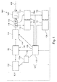
- FIG. 1 illustrates a fiber measurement device 100, embodied as a Distributed Temperature Sensing (DTS) system, according to an exemplary embodiment of the invention.
- DTS Distributed Temperature Sensing
- the fiber measurement device 100 comprising a laser as an electromagnetic radiation source 102 configured for generating pulses of electromagnetic radiation as primary electromagnetic radiation to be coupled into a fiber 108 for a DTS measurement.
- the electromagnetic radiation emitted by the electromagnetic radiation source 102 may be near infrared light, for instance with a wavelength in a range between 1000 nm and 1600 nm.
- the length of the individual pulses may be several nanoseconds, for instance 5 ns.
- a determining unit 104 is provided and configured for determining a potential deviation between a predefined target shape and an actual shape of the pulses generated and emitted by the electromagnetic radiation source 102.
- An adjustment unit 106 may be configured for adjusting the shape of the pulses for correcting or compensating the deviation between the theoretically desired target shape and the real or actual shape as emitted by the electromagnetic radiation source 102 although attempting to generate pulses of the target shape.
- the determining unit 104 and the adjustment unit 106 which may be embodied as individual processors or one common processor, include several subcomponents which will be described below in further detail.
- the amplifier 114 may be a fiber amplifier (such as a piece of pumped fiber for stimulating emission, for instance an erbium doped fiber amplifier, EDFA) or a solid-state laser.
- the primary electromagnetic radiation then propagates along the fiber 108, in a way as known by those skilled in the art of DTS, and is backscattered so that secondary electromagnetic radiation propagates backwardly along the fiber 108.
- the backscattered secondary electromagnetic radiation includes information concerning the physical entity to be sensed, such as a temperature distribution along the spatial extension of the fiber 108.
- An electromagnetic radiation detector 110 for instance a photodetector, is configured for detecting the secondary electromagnetic radiation which has been generated in the fiber 108 in response to the coupling of the primary electromagnetic radiation into the fiber 108.
- a pre-processing unit 110a (which may either form part of the electromagnetic radiation detector 110 or may be provided, in a signal flow path, downstream of the electromagnetic radiation detector 110) which is configured for pre-processing the detection signals before forwarding the (then pre-processed) detection signals to one or more of the units indicated with reference numeral 132, 130.
- An evaluation unit 130 is configured for evaluating the detected secondary electromagnetic radiation for determining information indicative of the physical quantity, i.e. for determining the temperature distribution along the fiber 108.
- a determination unit 104 may even be omitted in a scenario in which a deviation between a target pulse shape and an actual pulse shape is already known, for instance from historic measurements.
- the determining unit 104 is configured for determining the deviation by a separate electromagnetic radiation sensor 116, such as a photodiode.
- a beam splitter 118 or tap may be provided for splitting the primary electromagnetic radiation into a large first portion to be coupled into the fiber 108 and into a much smaller second portion to be coupled to the electromagnetic radiation sensor 116.
- the electromagnetic radiation sensor 116 may then detect the second portion and may use the corresponding detection data for analyzing pulse shape to thereby determine the actual pulse shape.
- the determined actual pulse shape may then be compared to the predefined target shape to determine the deviation.
- the determining unit 104 is configured for determining the deviation by analyzing actually detected secondary electromagnetic radiation concerning a predefined reference measurement feature obtained with the pulses having the actual shape (i.e. without correction or compensation). For instance, a standard spatial temperature event (such as a temperature step of 100°C at a predefined position of the fiber 108) may be applied and measured. The corresponding secondary electromagnetic radiation detected by the electromagnetic radiation detector 110 (wherein the beam splitter 118 can direct the secondary electromagnetic radiation or part thereof to the electromagnetic radiation detector 110) can then be evaluated with the knowledge that the temperature difference is 100°C at the predefined position of the fiber 108. A discrepancy between the actually detected secondary electromagnetic radiation and secondary electromagnetic radiation expected for this standard temperature event is then due to pulse shape artifacts which allows to calculate the deviation of the actual pulse shape from the predefined target pulse shape.
- a standard spatial temperature event such as a temperature step of 100°C at a predefined position of the fiber 108
- the corresponding secondary electromagnetic radiation detected by the electromagnetic radiation detector 110 (wherein the beam splitter 118 can
- the determining unit 104 is configured for determining the deviation based on a predefined model concerning imperfection of the shape of the pulses before being coupled into the fiber 108.
- a database 134 may comprise corresponding data of such a model of imperfections of the shape of the pulses.
- the adjustment unit 106 is configured for controlling, under control of a control unit 132 (such as a processor, which may be a separate processor or may form part of one of the above-mentioned processors), the electromagnetic radiation source 102 for generating the pulses already with adjusted shape. More specifically, the control unit 132 of the adjustment unit 106 may be configured for adjusting a drive current or a drive voltage of the electromagnetic radiation source 102 for generating the pulses with the adjusted shape. Thus, future pulses may already be emitted by the electromagnetic radiation source 102 with a corrected pulse shape.
- a control unit 132 such as a processor, which may be a separate processor or may form part of one of the above-mentioned processors
- the control unit 132 of the adjustment unit 106 may be configured for adjusting a drive current or a drive voltage of the electromagnetic radiation source 102 for generating the pulses with the adjusted shape.
- future pulses may already be emitted by the electromagnetic radiation source 102 with a corrected pulse shape.
- the adjustment unit 106 may be configured for adjusting shape of the pulses after its generation by the electromagnetic radiation source 102.
- the adjustment unit 106 may comprise an electromagnetic radiation manipulator 112 (such as an AOM or an EOM) configured for adjusting the shape of the pulses by manipulating the generated primary electromagnetic radiation prior to being coupled into the fiber 108.
- an electromagnetic radiation manipulator 112 such as an AOM or an EOM
- already present amplifier 114 may be synergistically used for this purpose.
- the positions of the electromagnetic radiation manipulator 112 and of the amplifier 114 may be also interexchanged.
- the electromagnetic radiation manipulator 112 may be configured for attenuating and/or amplifying an intensity profile of the pulses for adjusting their shape.
- the respective pulses may be shaped in the electromagnetic radiation manipulator 112 and may continue to propagate on their path towards optional optical amplifier 114.
- the adjustment unit 106 may be configured for adjusting the shape by averaging the acquired backscatter signal over multiple emissions of a pulse train. This may be done by manipulating, in particular varying or switching off, a part of the averaged multiple pulses. This may also be done by sending only pulses with power above a predefined power value and subtracting a backscattering signal of the secondary electromagnetic radiation. Furthermore, this can be done by sending only pulses with power below a predefined power value.
- the determining unit 104 and the adjustment unit 106 form part of a control loop 120 in which the deviation is determined and the shape is adjusted.
- the control loop 120 can be provided in parallel to the measurement or optical path 122 so that the measurement can be continued during the pulse shape correction.
- Reference numerals 116 and/or 110 and/or 134 may therefore form determining unit 104 determining a deviation between a predefined target shape and actual shape of the pulse.
- Control unit 132 controlling the pulse generation of the fiber measurement device 100 may be supplied with the data from the determining unit 104 indicative of the deviation between the target shape and the actual shape.
- the pulse generation and correction may run independently from the overall measurement evaluation.
- the control unit 132 may control the electromagnetic radiation source 102 and/or the electromagnetic radiation manipulator 112 and/or the optional amplifier 114 so as to partially or fully compensate the deviation.
- an electromagnetic radiation source control unit 132a configured for controlling electromagnetic radiation emission of the electromagnetic radiation source 102 based on control signals received from the control unit 132.
- the actual shape may correspond to the target shape.
- the pulse shape correction may be performed prior to the detection of the secondary electromagnetic radiation by the electromagnetic radiation detector 110, in particular before coupling the primary electromagnetic radiation into the fiber 108.
- the beam splitter 118 in particular what concerns the outcoupling of the secondary electromagnetic radiation beam, it is possible to implement a wavelength splitter (such as a WDM element, wavelength division multiplexer) or a circulator.
- a wavelength splitter such as a WDM element, wavelength division multiplexer
- a pre-known reference spatial event at the measurement fiber 108 alternatively inside the instrument along the measured path (such as a high temperatures spot at a certain position along the measurement fiber 108) is present. It is furthermore possible that determining and adjusting is accomplished in the presence of such a pre-known reference spatial event.
- control of the drive voltage for driving the electromagnetic radiation source 102 is integrated in the control unit 132.
- the drive voltage or any other drive signal may be generated and/or controlled also by another entity than the control unit 132.
- the determination of the deviation is carried out by the determining unit 104 based on the generated initial pulse (see reference numeral 116) and/or based on the detected response pulse (see reference numeral 110) and/or based on model data (see reference numeral 134).
- the determination of the deviation may be carried out by the determining unit 104 also on the basis of an intermediate or final result of the physical quantity to be determined (such as on the basis of a temperature signal or a pre-form thereof). For instance in case of DTS, the Stokes signal and the Antistokes signal are extracted from the detection signals detected by the electromagnetic radiation detector 110.
- the temperature distribution along the measurement fiber 108 is then determined based on a ratio between Stokes signal and Antistokes signal. Hence, certain calculations are carried out in order to obtain the physical quantity based on the detection signal. During these calculation, intermediate results and a final result are obtained. Any of these intermediate (see reference numeral 110a) or final (see reference numeral 130) results may be used as a basis for the determination of the distortion.
- Figure 2 illustrates an ideal target shape 200 of a sequence of pulses 202.
- the target shape 200 in this scenario is a rectangular shape, wherein different pulses 202 of the shown pulse train have different lengths in time or space.
- Figure 3 and Figure 4 illustrate for the sequence of pulses 202 according to Figure 2 actual pulse shapes 300 as occurring during a real measurement.
- Figure 3 and Figure 4 show different pulse shape deviations or imperfections which may be considered for at least partially compensating them according to exemplary embodiments of the invention.
- the artifacts according to Figure 3 relate to inductivity effects. Deviation features shown in Figure 3 are overshoots 302, delays 304 and rounded edges 306.
- Figure 4 additionally shows artefacts resulting from an amplifier, more specifically a gain decay of a pre-pumped amplifier. This results in a non-horizontal envelope 400 having an impact on the intensity of the pulses 202. In other words, envelope 400 renders the intensity of the pulses 202 unequal.
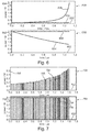
- Figure 5 shows a diagram 500 having an abscissa 502 along which the time is plotted. Along an ordinate 504, a gain is plotted.
- Figure 5 shows pulse trains 508 of individual pulses 202. Intervals of re-pumping are denoted with reference numeral 510. For instance, one interval of re-pumping 510 takes several milliseconds, whereas one interval of a pulse train 508 takes several microseconds.
- An envelope 400 is shown.
- Figure 5 therefore shows amplifier loading and depletion and also shows corresponding pulse shape artefacts which may be at least partially compensated according to an exemplary embodiment of the invention.
- an amplifier depletion compensation model will be presented in the following. More specifically, an example of a fiber amplifier will be given which gets depleted during measurement.
- a target may be to keep the output power Pout of the amplifier constant over time t during a single pulse emission (input power P in ):
- An amplifier model may relate to an optical load. Thus, gain may reduce proportional with the emitted power. It may be assumed that re-pumping occurs on much longer time scale than a pulse length, thus re-pumping during emission is omitted or neglected.
- a single pulse will be considered in the following (this consideration applies also to a sequence of pulses):
- a pulse train will be considered in the following:
- Figure 7 shows diagrams 700, 750 illustrating, for the example of a pulse train, a dependence of input power and output power over time for different kinds of compensation according to exemplary embodiments of the invention.
Landscapes
- Physics & Mathematics (AREA)
- General Physics & Mathematics (AREA)
- Optics & Photonics (AREA)
- Chemical & Material Sciences (AREA)
- Analytical Chemistry (AREA)
- Engineering & Computer Science (AREA)
- Microelectronics & Electronic Packaging (AREA)
- Length Measuring Devices By Optical Means (AREA)
- Investigating Or Analysing Materials By Optical Means (AREA)
- Optical Transform (AREA)
- Measuring Temperature Or Quantity Of Heat (AREA)
Applications Claiming Priority (1)
| Application Number | Priority Date | Filing Date | Title |
|---|---|---|---|
| DE102015113581.7A DE102015113581B4 (de) | 2015-08-17 | 2015-08-17 | Fasermessung mit Impulsformung |
Publications (2)
| Publication Number | Publication Date |
|---|---|
| EP3141880A1 true EP3141880A1 (fr) | 2017-03-15 |
| EP3141880B1 EP3141880B1 (fr) | 2018-11-14 |
Family
ID=56787289
Family Applications (1)
| Application Number | Title | Priority Date | Filing Date |
|---|---|---|---|
| EP16184410.5A Active EP3141880B1 (fr) | 2015-08-17 | 2016-08-16 | Mesure de fibre avec mise en forme d'impulsion |
Country Status (3)
| Country | Link |
|---|---|
| US (1) | US10209100B2 (fr) |
| EP (1) | EP3141880B1 (fr) |
| DE (1) | DE102015113581B4 (fr) |
Cited By (1)
| Publication number | Priority date | Publication date | Assignee | Title |
|---|---|---|---|---|
| GB2558295A (en) * | 2016-12-23 | 2018-07-11 | Aiq Dienstleistungen Ug Haftungsbeschrankt | A distributed lightning stroke detection system operating in a monitoring mode |
Families Citing this family (8)
| Publication number | Priority date | Publication date | Assignee | Title |
|---|---|---|---|---|
| DE102017207898A1 (de) * | 2017-05-10 | 2018-11-15 | Siemens Aktiengesellschaft | Umrichteranordnung mit Brandmeldeanlage |
| GB2571540B (en) * | 2018-02-28 | 2020-10-28 | Craley Group Ltd | Improvements in or relating to the monitoring of fluid pipes |
| KR102727159B1 (ko) * | 2019-01-09 | 2024-11-12 | 한국전자통신연구원 | 패턴 기반 복조 방식의 백스캐터 통신 방법 및 장치 |
| US11193801B2 (en) * | 2019-05-22 | 2021-12-07 | Nec Corporation | Amplifier dynamics compensation for brillouin optical time-domain reflectometry |
| US11296786B2 (en) * | 2020-04-07 | 2022-04-05 | Nec Corporation | Constant amplitude coded DFOS using out-of-band signaling |
| US20210348971A1 (en) * | 2020-05-07 | 2021-11-11 | Ut-Battelle, Llc | Post-processing method to extend the functional range of optical backscatter reflectometry in extreme environments |
| KR102299905B1 (ko) * | 2021-02-26 | 2021-09-09 | 주식회사 에니트 | 광 검출부 이득조절 기반 광섬유 분산 음향 감지 센서를 이용한 감시 시스템 및 그 방법 |
| CN116054931B (zh) * | 2023-02-21 | 2026-03-27 | 桂林聚联科技有限公司 | 一种光纤测量数据的补偿方法、装置、设备和存储介质 |
Citations (2)
| Publication number | Priority date | Publication date | Assignee | Title |
|---|---|---|---|---|
| WO2004073172A2 (fr) * | 2003-02-12 | 2004-08-26 | Sensornet Limited | Procede et dispositif de production et d'emission d'impulsions optiques de haute energie pour mesures de grandes distances |
| EP2775278A2 (fr) | 2013-03-06 | 2014-09-10 | Yokogawa Electric Corporation | Dispositif et procédé de mesure de répartition de température à fibre optique |
Family Cites Families (6)
| Publication number | Priority date | Publication date | Assignee | Title |
|---|---|---|---|---|
| DE3837591A1 (de) * | 1988-11-05 | 1990-05-10 | Ant Nachrichtentech | Verfahren zum ermitteln der uebertragungseigenschaften eines lichtwellenleiters |
| US5069544A (en) | 1990-04-12 | 1991-12-03 | Minnesota Mining And Manufacturing Company | Adaptive pulse width optical fault finder |
| JP3292982B2 (ja) * | 1997-10-09 | 2002-06-17 | アンリツ株式会社 | 光ファイバ特性評価装置及びプログラムを記録した媒体 |
| AU2002951705A0 (en) * | 2002-09-27 | 2002-10-17 | Crc For Intelligent Manufacturing Systems And Technologies Ltd | Reflectometry |
| US8311069B2 (en) * | 2007-12-21 | 2012-11-13 | Board Of Trustees Of Michigan State University | Direct ultrashort laser system |
| DE102014200954A1 (de) * | 2014-01-21 | 2015-07-23 | Bayerische Motoren Werke Aktiengesellschaft | Erfassung von lokalen mechanischen Belastungen |
-
2015
- 2015-08-17 DE DE102015113581.7A patent/DE102015113581B4/de active Active
-
2016
- 2016-08-16 US US15/238,658 patent/US10209100B2/en active Active
- 2016-08-16 EP EP16184410.5A patent/EP3141880B1/fr active Active
Patent Citations (2)
| Publication number | Priority date | Publication date | Assignee | Title |
|---|---|---|---|---|
| WO2004073172A2 (fr) * | 2003-02-12 | 2004-08-26 | Sensornet Limited | Procede et dispositif de production et d'emission d'impulsions optiques de haute energie pour mesures de grandes distances |
| EP2775278A2 (fr) | 2013-03-06 | 2014-09-10 | Yokogawa Electric Corporation | Dispositif et procédé de mesure de répartition de température à fibre optique |
Non-Patent Citations (1)
| Title |
|---|
| KIMIHISHA OHNO ET AL: "Adaptive pulse shaping of phase and amplitude of an amplified femtosecond pulse laser by direct reference to frequency-resolved optical gating traces", JOURNAL OF THE OPTICAL SOCIETY OF AMERICA - B, vol. 19, no. 11, November 2002 (2002-11-01), pages 2781 - 2790, XP002572770, ISSN: 0740-3224 * |
Cited By (2)
| Publication number | Priority date | Publication date | Assignee | Title |
|---|---|---|---|---|
| GB2558295A (en) * | 2016-12-23 | 2018-07-11 | Aiq Dienstleistungen Ug Haftungsbeschrankt | A distributed lightning stroke detection system operating in a monitoring mode |
| GB2558295B (en) * | 2016-12-23 | 2020-04-08 | Aiq Dienstleistungen Ug Haftungsbeschraenkt | A distributed lightning stroke detection system operating in a monitoring mode |
Also Published As
| Publication number | Publication date |
|---|---|
| DE102015113581B4 (de) | 2021-02-04 |
| DE102015113581A1 (de) | 2017-02-23 |
| US20170052041A1 (en) | 2017-02-23 |
| EP3141880B1 (fr) | 2018-11-14 |
| US10209100B2 (en) | 2019-02-19 |
Similar Documents
| Publication | Publication Date | Title |
|---|---|---|
| EP3141880B1 (fr) | Mesure de fibre avec mise en forme d'impulsion | |
| Pastor-Graells et al. | Chirped-pulse phase-sensitive reflectometer assisted by first-order Raman amplification | |
| US7585107B2 (en) | Corrected DTS measurements based on Raman-Stokes signals | |
| US20150233767A1 (en) | Distributed Optical Sensing With Two-Step Evaluation | |
| EP3088914B1 (fr) | Appareil de mesure de distance, appareil électronique, procédé de mesure de distance et programme de mesure de distance | |
| US20130156066A1 (en) | Optic fiber distributed temperature sensor system with self-correction function and temperature measuring method using thereof | |
| US20100195088A1 (en) | Distance measuring instrument and method | |
| EP3093639A1 (fr) | Dispositifs de détection optique répartis et procédés permettant d'effectuer une mesure | |
| US10432306B2 (en) | Method and apparatus for measurement of a backscattered trace of a fiber | |
| WO2020050076A1 (fr) | Appareil de mesure de caractéristique de fibre optique et procédé de mesure de caractéristique de fibre optique | |
| JP2008286697A (ja) | 分布型光ファイバセンサ | |
| CN110940487A (zh) | 测量装置和测量方法 | |
| JP3880873B2 (ja) | 多重光路干渉光測定方法および測定装置 | |
| JP6484125B2 (ja) | 温度測定装置及び温度測定方法 | |
| JP5515199B2 (ja) | 光パルス試験装置及びその調整方法 | |
| JP2011064573A (ja) | 光ファイバの障害点検出装置 | |
| JP2010014598A (ja) | 距離測定装置 | |
| JP5061981B2 (ja) | 光パルス試験器および光パルス試験器の光パワー安定化方法 | |
| JP3065832B2 (ja) | 温度分布検出装置 | |
| GB2541496A (en) | Distributed sensing considering two relations between measurement signals | |
| JP3065833B2 (ja) | 温度分布検出装置 | |
| JP2747565B2 (ja) | 光ファイバの曲率分布測定方法および装置 | |
| JPS58113832A (ja) | 光フアイバ破断点検出装置 | |
| Galal et al. | Enhanced signal-associated noise in a φ-OTDR system | |
| JP2009276287A (ja) | ラマン利得効率測定方法および装置 |
Legal Events
| Date | Code | Title | Description |
|---|---|---|---|
| PUAI | Public reference made under article 153(3) epc to a published international application that has entered the european phase |
Free format text: ORIGINAL CODE: 0009012 |
|
| STAA | Information on the status of an ep patent application or granted ep patent |
Free format text: STATUS: THE APPLICATION HAS BEEN PUBLISHED |
|
| AK | Designated contracting states |
Kind code of ref document: A1 Designated state(s): AL AT BE BG CH CY CZ DE DK EE ES FI FR GB GR HR HU IE IS IT LI LT LU LV MC MK MT NL NO PL PT RO RS SE SI SK SM TR |
|
| AX | Request for extension of the european patent |
Extension state: BA ME |
|
| STAA | Information on the status of an ep patent application or granted ep patent |
Free format text: STATUS: REQUEST FOR EXAMINATION WAS MADE |
|
| 17P | Request for examination filed |
Effective date: 20170915 |
|
| RBV | Designated contracting states (corrected) |
Designated state(s): AL AT BE BG CH CY CZ DE DK EE ES FI FR GB GR HR HU IE IS IT LI LT LU LV MC MK MT NL NO PL PT RO RS SE SI SK SM TR |
|
| GRAP | Despatch of communication of intention to grant a patent |
Free format text: ORIGINAL CODE: EPIDOSNIGR1 |
|
| STAA | Information on the status of an ep patent application or granted ep patent |
Free format text: STATUS: GRANT OF PATENT IS INTENDED |
|
| RIC1 | Information provided on ipc code assigned before grant |
Ipc: G01K 11/32 20060101AFI20180523BHEP Ipc: G01L 1/24 20060101ALI20180523BHEP Ipc: G01D 5/353 20060101ALI20180523BHEP Ipc: G01M 11/00 20060101ALI20180523BHEP |
|
| INTG | Intention to grant announced |
Effective date: 20180615 |
|
| GRAS | Grant fee paid |
Free format text: ORIGINAL CODE: EPIDOSNIGR3 |
|
| GRAA | (expected) grant |
Free format text: ORIGINAL CODE: 0009210 |
|
| STAA | Information on the status of an ep patent application or granted ep patent |
Free format text: STATUS: THE PATENT HAS BEEN GRANTED |
|
| AK | Designated contracting states |
Kind code of ref document: B1 Designated state(s): AL AT BE BG CH CY CZ DE DK EE ES FI FR GB GR HR HU IE IS IT LI LT LU LV MC MK MT NL NO PL PT RO RS SE SI SK SM TR |
|
| REG | Reference to a national code |
Ref country code: CH Ref legal event code: EP Ref country code: AT Ref legal event code: REF Ref document number: 1065394 Country of ref document: AT Kind code of ref document: T Effective date: 20181115 |
|
| REG | Reference to a national code |
Ref country code: DE Ref legal event code: R096 Ref document number: 602016007095 Country of ref document: DE |
|
| REG | Reference to a national code |
Ref country code: IE Ref legal event code: FG4D |
|
| REG | Reference to a national code |
Ref country code: NL Ref legal event code: MP Effective date: 20181114 |
|
| REG | Reference to a national code |
Ref country code: LT Ref legal event code: MG4D |
|
| REG | Reference to a national code |
Ref country code: AT Ref legal event code: MK05 Ref document number: 1065394 Country of ref document: AT Kind code of ref document: T Effective date: 20181114 |
|
| PG25 | Lapsed in a contracting state [announced via postgrant information from national office to epo] |
Ref country code: LT Free format text: LAPSE BECAUSE OF FAILURE TO SUBMIT A TRANSLATION OF THE DESCRIPTION OR TO PAY THE FEE WITHIN THE PRESCRIBED TIME-LIMIT Effective date: 20181114 Ref country code: FI Free format text: LAPSE BECAUSE OF FAILURE TO SUBMIT A TRANSLATION OF THE DESCRIPTION OR TO PAY THE FEE WITHIN THE PRESCRIBED TIME-LIMIT Effective date: 20181114 Ref country code: NO Free format text: LAPSE BECAUSE OF FAILURE TO SUBMIT A TRANSLATION OF THE DESCRIPTION OR TO PAY THE FEE WITHIN THE PRESCRIBED TIME-LIMIT Effective date: 20190214 Ref country code: IS Free format text: LAPSE BECAUSE OF FAILURE TO SUBMIT A TRANSLATION OF THE DESCRIPTION OR TO PAY THE FEE WITHIN THE PRESCRIBED TIME-LIMIT Effective date: 20190314 Ref country code: AT Free format text: LAPSE BECAUSE OF FAILURE TO SUBMIT A TRANSLATION OF THE DESCRIPTION OR TO PAY THE FEE WITHIN THE PRESCRIBED TIME-LIMIT Effective date: 20181114 Ref country code: LV Free format text: LAPSE BECAUSE OF FAILURE TO SUBMIT A TRANSLATION OF THE DESCRIPTION OR TO PAY THE FEE WITHIN THE PRESCRIBED TIME-LIMIT Effective date: 20181114 Ref country code: ES Free format text: LAPSE BECAUSE OF FAILURE TO SUBMIT A TRANSLATION OF THE DESCRIPTION OR TO PAY THE FEE WITHIN THE PRESCRIBED TIME-LIMIT Effective date: 20181114 Ref country code: HR Free format text: LAPSE BECAUSE OF FAILURE TO SUBMIT A TRANSLATION OF THE DESCRIPTION OR TO PAY THE FEE WITHIN THE PRESCRIBED TIME-LIMIT Effective date: 20181114 Ref country code: BG Free format text: LAPSE BECAUSE OF FAILURE TO SUBMIT A TRANSLATION OF THE DESCRIPTION OR TO PAY THE FEE WITHIN THE PRESCRIBED TIME-LIMIT Effective date: 20190214 |
|
| PG25 | Lapsed in a contracting state [announced via postgrant information from national office to epo] |
Ref country code: PT Free format text: LAPSE BECAUSE OF FAILURE TO SUBMIT A TRANSLATION OF THE DESCRIPTION OR TO PAY THE FEE WITHIN THE PRESCRIBED TIME-LIMIT Effective date: 20190314 Ref country code: NL Free format text: LAPSE BECAUSE OF FAILURE TO SUBMIT A TRANSLATION OF THE DESCRIPTION OR TO PAY THE FEE WITHIN THE PRESCRIBED TIME-LIMIT Effective date: 20181114 Ref country code: AL Free format text: LAPSE BECAUSE OF FAILURE TO SUBMIT A TRANSLATION OF THE DESCRIPTION OR TO PAY THE FEE WITHIN THE PRESCRIBED TIME-LIMIT Effective date: 20181114 Ref country code: SE Free format text: LAPSE BECAUSE OF FAILURE TO SUBMIT A TRANSLATION OF THE DESCRIPTION OR TO PAY THE FEE WITHIN THE PRESCRIBED TIME-LIMIT Effective date: 20181114 Ref country code: RS Free format text: LAPSE BECAUSE OF FAILURE TO SUBMIT A TRANSLATION OF THE DESCRIPTION OR TO PAY THE FEE WITHIN THE PRESCRIBED TIME-LIMIT Effective date: 20181114 |
|
| PG25 | Lapsed in a contracting state [announced via postgrant information from national office to epo] |
Ref country code: CZ Free format text: LAPSE BECAUSE OF FAILURE TO SUBMIT A TRANSLATION OF THE DESCRIPTION OR TO PAY THE FEE WITHIN THE PRESCRIBED TIME-LIMIT Effective date: 20181114 Ref country code: PL Free format text: LAPSE BECAUSE OF FAILURE TO SUBMIT A TRANSLATION OF THE DESCRIPTION OR TO PAY THE FEE WITHIN THE PRESCRIBED TIME-LIMIT Effective date: 20181114 Ref country code: DK Free format text: LAPSE BECAUSE OF FAILURE TO SUBMIT A TRANSLATION OF THE DESCRIPTION OR TO PAY THE FEE WITHIN THE PRESCRIBED TIME-LIMIT Effective date: 20181114 Ref country code: IT Free format text: LAPSE BECAUSE OF FAILURE TO SUBMIT A TRANSLATION OF THE DESCRIPTION OR TO PAY THE FEE WITHIN THE PRESCRIBED TIME-LIMIT Effective date: 20181114 |
|
| REG | Reference to a national code |
Ref country code: DE Ref legal event code: R097 Ref document number: 602016007095 Country of ref document: DE |
|
| PG25 | Lapsed in a contracting state [announced via postgrant information from national office to epo] |
Ref country code: EE Free format text: LAPSE BECAUSE OF FAILURE TO SUBMIT A TRANSLATION OF THE DESCRIPTION OR TO PAY THE FEE WITHIN THE PRESCRIBED TIME-LIMIT Effective date: 20181114 Ref country code: SM Free format text: LAPSE BECAUSE OF FAILURE TO SUBMIT A TRANSLATION OF THE DESCRIPTION OR TO PAY THE FEE WITHIN THE PRESCRIBED TIME-LIMIT Effective date: 20181114 Ref country code: RO Free format text: LAPSE BECAUSE OF FAILURE TO SUBMIT A TRANSLATION OF THE DESCRIPTION OR TO PAY THE FEE WITHIN THE PRESCRIBED TIME-LIMIT Effective date: 20181114 Ref country code: SK Free format text: LAPSE BECAUSE OF FAILURE TO SUBMIT A TRANSLATION OF THE DESCRIPTION OR TO PAY THE FEE WITHIN THE PRESCRIBED TIME-LIMIT Effective date: 20181114 |
|
| PLBE | No opposition filed within time limit |
Free format text: ORIGINAL CODE: 0009261 |
|
| STAA | Information on the status of an ep patent application or granted ep patent |
Free format text: STATUS: NO OPPOSITION FILED WITHIN TIME LIMIT |
|
| 26N | No opposition filed |
Effective date: 20190815 |
|
| PG25 | Lapsed in a contracting state [announced via postgrant information from national office to epo] |
Ref country code: SI Free format text: LAPSE BECAUSE OF FAILURE TO SUBMIT A TRANSLATION OF THE DESCRIPTION OR TO PAY THE FEE WITHIN THE PRESCRIBED TIME-LIMIT Effective date: 20181114 |
|
| PG25 | Lapsed in a contracting state [announced via postgrant information from national office to epo] |
Ref country code: TR Free format text: LAPSE BECAUSE OF FAILURE TO SUBMIT A TRANSLATION OF THE DESCRIPTION OR TO PAY THE FEE WITHIN THE PRESCRIBED TIME-LIMIT Effective date: 20181114 |
|
| PG25 | Lapsed in a contracting state [announced via postgrant information from national office to epo] |
Ref country code: LI Free format text: LAPSE BECAUSE OF NON-PAYMENT OF DUE FEES Effective date: 20190831 Ref country code: CH Free format text: LAPSE BECAUSE OF NON-PAYMENT OF DUE FEES Effective date: 20190831 Ref country code: MC Free format text: LAPSE BECAUSE OF FAILURE TO SUBMIT A TRANSLATION OF THE DESCRIPTION OR TO PAY THE FEE WITHIN THE PRESCRIBED TIME-LIMIT Effective date: 20181114 Ref country code: LU Free format text: LAPSE BECAUSE OF NON-PAYMENT OF DUE FEES Effective date: 20190816 |
|
| REG | Reference to a national code |
Ref country code: BE Ref legal event code: MM Effective date: 20190831 |
|
| PG25 | Lapsed in a contracting state [announced via postgrant information from national office to epo] |
Ref country code: IE Free format text: LAPSE BECAUSE OF NON-PAYMENT OF DUE FEES Effective date: 20190816 |
|
| PG25 | Lapsed in a contracting state [announced via postgrant information from national office to epo] |
Ref country code: BE Free format text: LAPSE BECAUSE OF NON-PAYMENT OF DUE FEES Effective date: 20190831 |
|
| PG25 | Lapsed in a contracting state [announced via postgrant information from national office to epo] |
Ref country code: CY Free format text: LAPSE BECAUSE OF FAILURE TO SUBMIT A TRANSLATION OF THE DESCRIPTION OR TO PAY THE FEE WITHIN THE PRESCRIBED TIME-LIMIT Effective date: 20181114 |
|
| PG25 | Lapsed in a contracting state [announced via postgrant information from national office to epo] |
Ref country code: GR Free format text: LAPSE BECAUSE OF FAILURE TO SUBMIT A TRANSLATION OF THE DESCRIPTION OR TO PAY THE FEE WITHIN THE PRESCRIBED TIME-LIMIT Effective date: 20181114 |
|
| PG25 | Lapsed in a contracting state [announced via postgrant information from national office to epo] |
Ref country code: MT Free format text: LAPSE BECAUSE OF FAILURE TO SUBMIT A TRANSLATION OF THE DESCRIPTION OR TO PAY THE FEE WITHIN THE PRESCRIBED TIME-LIMIT Effective date: 20181114 Ref country code: HU Free format text: LAPSE BECAUSE OF FAILURE TO SUBMIT A TRANSLATION OF THE DESCRIPTION OR TO PAY THE FEE WITHIN THE PRESCRIBED TIME-LIMIT; INVALID AB INITIO Effective date: 20160816 |
|
| PG25 | Lapsed in a contracting state [announced via postgrant information from national office to epo] |
Ref country code: MK Free format text: LAPSE BECAUSE OF FAILURE TO SUBMIT A TRANSLATION OF THE DESCRIPTION OR TO PAY THE FEE WITHIN THE PRESCRIBED TIME-LIMIT Effective date: 20181114 |
|
| P01 | Opt-out of the competence of the unified patent court (upc) registered |
Effective date: 20230523 |
|
| PGFP | Annual fee paid to national office [announced via postgrant information from national office to epo] |
Ref country code: DE Payment date: 20250831 Year of fee payment: 10 |
|
| PGFP | Annual fee paid to national office [announced via postgrant information from national office to epo] |
Ref country code: GB Payment date: 20250811 Year of fee payment: 10 |
|
| PGFP | Annual fee paid to national office [announced via postgrant information from national office to epo] |
Ref country code: FR Payment date: 20250808 Year of fee payment: 10 |