EP3141895A1 - Procédé d'analyse d'azote et dispositif d'analyse d'azote - Google Patents
Procédé d'analyse d'azote et dispositif d'analyse d'azote Download PDFInfo
- Publication number
- EP3141895A1 EP3141895A1 EP15812869.4A EP15812869A EP3141895A1 EP 3141895 A1 EP3141895 A1 EP 3141895A1 EP 15812869 A EP15812869 A EP 15812869A EP 3141895 A1 EP3141895 A1 EP 3141895A1
- Authority
- EP
- European Patent Office
- Prior art keywords
- specimen
- nitrogen
- concentration
- diluted
- solvent
- Prior art date
- Legal status (The legal status is an assumption and is not a legal conclusion. Google has not performed a legal analysis and makes no representation as to the accuracy of the status listed.)
- Granted
Links
Images


Classifications
-
- G—PHYSICS
- G01—MEASURING; TESTING
- G01N—INVESTIGATING OR ANALYSING MATERIALS BY DETERMINING THEIR CHEMICAL OR PHYSICAL PROPERTIES
- G01N21/00—Investigating or analysing materials by the use of optical means, i.e. using sub-millimetre waves, infrared, visible or ultraviolet light
- G01N21/17—Systems in which incident light is modified in accordance with the properties of the material investigated
- G01N21/25—Colour; Spectral properties, i.e. comparison of effect of material on the light at two or more different wavelengths or wavelength bands
- G01N21/27—Colour; Spectral properties, i.e. comparison of effect of material on the light at two or more different wavelengths or wavelength bands using photo-electric detection ; circuits for computing concentration
- G01N21/274—Calibration, base line adjustment, drift correction
-
- G—PHYSICS
- G01—MEASURING; TESTING
- G01N—INVESTIGATING OR ANALYSING MATERIALS BY DETERMINING THEIR CHEMICAL OR PHYSICAL PROPERTIES
- G01N1/00—Sampling; Preparing specimens for investigation
- G01N1/02—Devices for withdrawing samples
- G01N1/22—Devices for withdrawing samples in the gaseous state
- G01N1/24—Suction devices
-
- G—PHYSICS
- G01—MEASURING; TESTING
- G01N—INVESTIGATING OR ANALYSING MATERIALS BY DETERMINING THEIR CHEMICAL OR PHYSICAL PROPERTIES
- G01N1/00—Sampling; Preparing specimens for investigation
- G01N1/28—Preparing specimens for investigation including physical details of (bio-)chemical methods covered elsewhere, e.g. G01N33/50, C12Q
- G01N1/38—Diluting, dispersing or mixing samples
-
- G—PHYSICS
- G01—MEASURING; TESTING
- G01N—INVESTIGATING OR ANALYSING MATERIALS BY DETERMINING THEIR CHEMICAL OR PHYSICAL PROPERTIES
- G01N21/00—Investigating or analysing materials by the use of optical means, i.e. using sub-millimetre waves, infrared, visible or ultraviolet light
- G01N21/75—Systems in which material is subjected to a chemical reaction, the progress or the result of the reaction being investigated
- G01N21/76—Chemiluminescence; Bioluminescence
- G01N21/766—Chemiluminescence; Bioluminescence of gases
-
- G—PHYSICS
- G01—MEASURING; TESTING
- G01N—INVESTIGATING OR ANALYSING MATERIALS BY DETERMINING THEIR CHEMICAL OR PHYSICAL PROPERTIES
- G01N33/00—Investigating or analysing materials by specific methods not covered by groups G01N1/00 - G01N31/00
- G01N33/0004—Gaseous mixtures, e.g. polluted air
- G01N33/0009—General constructional details of gas analysers, e.g. portable test equipment
- G01N33/0011—Sample conditioning
- G01N33/0013—Sample conditioning by a chemical reaction
-
- G—PHYSICS
- G01—MEASURING; TESTING
- G01N—INVESTIGATING OR ANALYSING MATERIALS BY DETERMINING THEIR CHEMICAL OR PHYSICAL PROPERTIES
- G01N1/00—Sampling; Preparing specimens for investigation
- G01N1/02—Devices for withdrawing samples
- G01N1/22—Devices for withdrawing samples in the gaseous state
- G01N1/24—Suction devices
- G01N2001/247—Syringes
-
- G—PHYSICS
- G01—MEASURING; TESTING
- G01N—INVESTIGATING OR ANALYSING MATERIALS BY DETERMINING THEIR CHEMICAL OR PHYSICAL PROPERTIES
- G01N2201/00—Features of devices classified in G01N21/00
- G01N2201/06—Illumination; Optics
Definitions
- the present invention relates to a nitrogen analyzing method and a nitrogen analyzer, and more particularly, to a nitrogen analyzing method, specifically, a method for quantitative analysis of nitrogen in a specimen by a chemiluminescence method using ozone which is capable of measuring a concentration of nitrogen contained in a specimen such as, for example, petroleum, with still higher accuracy, and a nitrogen analyzer used for practicing the analyzing method.
- a specimen is injected into a reaction tube, and the reaction tube is heated while feeding oxygen thereinto to burn the specimen and recover a specimen gas from the reaction tube, and then the resulting specimen gas is allowed to react with ozone generated in an ozone generator to thereby measure a chemiluminescence intensity due to the reaction using a chemiluminescence detector.
- the specimen to be measured is diluted with a solvent to prepare a diluted specimen having an appropriate concentration, and the resulting diluted specimen is subjected to the above analysis procedure in view of measuring ranges of the chemiluminescence detector and handling property of the specimen.
- the reason why the specimen is diluted as the pretreatment in the above nitrogen analysis is as follows. That is, when the concentrations of nitrogen in the respective specimens are largely different from each other, the production efficiency of nitrogen monoxide upon combustion of each specimen is also varied. Therefore, even when it is intended to use a calibration curve prepared based on the correlation of linear equation, since the dynamic range thereof tends to be excessively narrow, it is not possible to immediately utilize the calibration curve. For this reason, in the measurement, the specimen is appropriately diluted to such an extent that the concentration of nitrogen in the specimen is reduced to not more than 1000 ppm.
- the procedure for diluting the specimen requires skilled delicate technologies using a metering container such as a measuring flask, a whole pipette and a measuring pipette.
- a metering container such as a measuring flask, a whole pipette and a measuring pipette.
- the analysis accuracy is very low such that the true concentration is inconsistent with the analyzed value.
- the concentration of nitrogen in the specimen after being diluted is more than 1000 ppm
- deviation of the analyzed value from the true concentration is considerably increased.
- human errors tend to occur so that the analyzed value tends to be frequently fluctuated.
- the amount of the diluted specimen to be measured is very small, e.g., as small as about 50 ⁇ L, the diluted specimen tends to be prepared in as large an amount as 20 to 50 mL in the diluting procedure, so that a majority of the thus prepared diluted specimen must be discarded, which results in problems such as large environmental burden.
- An object of the present invention is to provide a nitrogen analyzing method in which a specimen comprising a nitrogen compound is burned, and the resulting specimen gas is allowed to react with ozone to measure a chemiluminescence intensity thereof, thereby conducting quantitative analysis of nitrogen in the specimen, and which is capable of measuring a concentration of nitrogen contained in the specimen with still higher accuracy, as well as a nitrogen analyzer for practicing the analyzing method. Also, another object of the present invention is to provide a nitrogen analyzing method and a nitrogen analyzer which have a less adverse influence on human body and are also capable of further reducing environmental burden even when analyzing nitrogen in the aforementioned fuel-related specimens.
- the present inventors first prepared a specimen having a known concentration.
- the specimen was previously diluted with a solvent to prepare diluted specimens having various different concentrations, and the resulting diluted specimens were subjected to measurement of the chemiluminescence intensity by the aforementioned analyzing method to analyze the relationship between the concentration of nitrogen in the diluted specimen and the chemiluminescence intensity.
- the concentration of nitrogen in the diluted specimen is in the range of 500 to 2500 ppm, 1000 to 5000 ppm, 3000 to 10000 ppm or 5000 to 20000 ppm, the correlation of linear equation is observed in the respective ranges, but slopes of the respective linear equations are different from each other.
- a nitrogen analyzing method comprising the steps of:
- a nitrogen analyzer mainly comprising a specimen gas feeding mechanism, a nitrogen analyzing mechanism and a computer for analysis
- the specimen gas feeding mechanism comprises a reaction tube having a double tube structure comprising an inner tube for introducing a liquid specimen which is provided at a head portion thereof with an automatic syringe and an outer tube for recovering the specimen gas through which oxygen is fed, and a heating furnace for heating the reaction tube, the specimen gas feeding mechanism having a function of heating and burning the specimen in the reaction tube by the heating furnace to convert nitrogen in the specimen into nitrogen monoxide and recover the nitrogen monoxide as the specimen gas
- the nitrogen analyzing mechanism comprises an ozone generator and a chemiluminescence detector, and is constructed such that a chemiluminescence intensity based on a reaction between the nitrogen monoxide in the specimen gas fed from the specimen gas feeding mechanism and ozone produced in the ozone generator is measured by the chemiluminescence detector; and wherein when injecting the specimen into
- the nitrogen analyzing method and the nitrogen analyzer according to the present invention by using the diluted specimen prepared by diluting the specimen into a specific concentration range, it is possible to maintain a constant production efficiency of nitrogen monoxide upon burning the specimen, and further since the weight of nitrogen in the specimen can be calculated based on an accurate calibration curve having an approximately proportional relation between the nitrogen concentration and a chemiluminescence intensity in the aforementioned specific concentration range, it is possible to measure concentrations of nitrogen in various specimens that are extremely different in nitrogen concentration from each other, with high accuracy.
- the preferred embodiments of the nitrogen analyzing method and the nitrogen analyzer according to the present invention are explained below by referring to the accompanying drawings.
- the analyzing method according to the present invention can be applied to various specimens described above, and can be practiced using the nitrogen analyzer utilizing chemiluminescence measured using ozone.
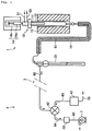
- the nitrogen analyzer is constructed mainly of a specimen gas feeding mechanism 1, a nitrogen analyzing mechanism 4 and a computer for analysis (not shown).
- the specimen gas feeding mechanism 1 comprises a reaction tube 10 into which the specimen is introduced and oxygen is fed, and a heating furnace 13 for heating the reaction tube, and has a function of heating and burning the specimen in the reaction tube 10 by the heating furnace to convert the nitrogen in the specimen into nitrogen monoxide and recover the nitrogen monoxide as the specimen gas.
- the reaction tube 10 has a double tube structure comprising an inner tube 11 for introducing the specimen and an outer tube 12 for recovering the specimen gas through which oxygen is fed.
- the inner tube 11 is provided at a heat portion thereof with an automatic syringe 14 as a specimen injecting device for injecting a liquid specimen.
- the inner tube 11 is designed so as to have an outer diameter smaller than an inner diameter of the outer tube 12 and a depth shorter than that of the outer tube 12 in order to ensure a clearance for allowing a gas to pass therethrough between an outer peripheral surface of the inner tube 11 and an inner peripheral surface of the outer tube 12.
- the inner tube 11 is connected at an upper portion thereof with a carrier gas feed passage 51 through which oxygen for promoting burning of the specimen and an inert gas such as argon for transportation are introduced.
- the outer tube 12 is constructed of an elongated cylindrical tube that is closed at a bottom end thereof and sealed at an upper end thereof.
- the outer tube 12 is connected at an upper portion thereof with an oxygen feed passage 52 for introducing oxygen for burning the specimen, and at a bottom thereof with a passage 61 for withdrawing the specimen gas obtained by burning the specimen.
- a heater 15 for heating conduits is disposed over an outer periphery of the passage 61 in order to completely oxidize the specimen gas.
- the heating furnace 13 serves as a heating means for heating the reaction tube 10, and is constructed of an electric furnace provided at a central portion thereof with a reaction tube insertion hole through which the reaction tube 10 is inserted. More specifically, the heating furnace 13 is constructed of a cylindrical casing, a heat insulator accommodated in the casing and a plurality of heaters embedded in the heat insulator, for example, sheathed heaters produced by accommodating a KANTHAL heating element, a nichrome heating element, a silver heating element or the like in a metal tube. Meanwhile, the heating furnace 13 is designed so as to detect a temperature of the reaction tube 10 and control energization of the heaters based on the temperature thus detected in order to maintain the reaction tube 10 at a predetermined temperature.
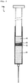
- the automatic syringe 14 is constructed of a microsyringe 14a for sampling and injecting the specimen and a plunger pump 14b for fixing the microsyringe and operating a plunger of the microsyringe.
- the microsyringe 14a is constructed of an elongated cylindrical syringe provided at one end thereof with a needle like an injection needle, and a plunger inserted into the syringe from the other end of the syringe (refer to FIG. 2 ).
- the plunger pump 14b comprises a base to which the syringe of the microsyringe 14a is fitted, and a movable element coupled to a base portion of the plunger of the microsyringe 14a and reciprocatively moved on the base along a longitudinal direction of the syringe of the microsyringe, and constructed so as to control a driving member such as a stepping motor by a controller having a suitable program written therein and operate the movable element at a predetermined speed.
- a driving member such as a stepping motor
- the specimen gas feeding mechanism 1 the specimen is injected into the inner tube from the automatic syringe 14 and fed from the inner tube 11 to the outer tube 12 by the aid of the oxygen and inert gas supplied through the carrier gas feed passage 51, and then while heating the outer tube 12 by the heating furnace 13, the specimen is oxidized and burned in a portion of the outer tube 12 located on the side of a tip end of the inner tube 11 by oxygen fed from the oxygen feed passage 52.
- the specimen gas feeding mechanism 1 is further constructed such that nitrogen in the specimen is converted into nitrogen monoxide and withdrawn as the specimen gas therefrom through the passage 61.
- a dehydration bath 21 filled, for example, with phosphoric acid as a dehydration agent is disposed to subject the specimen gas to dehydration and scrubbing (washing) of gases. More specifically, the passage 61 extending from the outer tube 12 of the reaction tube 10 is connected to the dehydration bath 21. A gas outlet of the dehydration bath 21 is connected to the nitrogen analyzing mechanism 4 through the passage 62. Meanwhile, the dehydration bath 21 may be constructed of a fluororesin tube filled with fluororesin fibers which has a function of removing water.
- the nitrogen analyzing mechanism 4 comprises an ozone generator 41 and a chemiluminescence detector 42, and is so designed as to measure an intensity of chemiluminescence generated by the reaction between nitrogen monoxide in the specimen gas fed from the specimen gas feeding mechanism 1 and ozone produced in the ozone generator 41 using the chemiluminescence detector 42.
- the ozone generator 41 a generator utilizing a so-called ozonizer microelement which has, for example, such a structure that a D.C.
- the chemiluminescence detector 42 is a detector of a reduced pressure chemiluminescence type in which light generated by the oxidation reaction is received by an electron multiplier tube and subjected to waveform processing to obtain an AREA value, and the amount of nitrogen in the specimen is measured from the AREA value using the below-mentioned previously prepared calibration curve. More specifically, in the nitrogen analysis using the chemiluminescence detector 42, nitrogen monoxide in the specimen gas is contacted with ozone to perform such an oxidation reaction as represented by NO + O 3 ⁇ NO 2 + O 2 + hN (wherein N is a frequency) to generate a light having a wavelength of 590 to 2500 nm. The thus generated light is received the electron multiplier tube to measure an intensity thereof, and subjected to the above processing.
- the ozone generator 41 is connected with an oxygen feed passage 53 for introducing oxygen for production of ozone thereinto.
- the oxygen feed passage 53 may be a passage branched from the oxygen feed passage 52.
- the chemiluminescence detector 42 is connected with a passage 63 for feed of ozone extending from the ozone generator 41, and is also connected with a passage 62 extending from the aforementioned dehydration bath 21.
- a detoxifying device 43 filled, for example, with activated carbon is disposed through a passage 64 to subject surplus ozone to detoxification treatment.
- a vacuum pump 7 is disposed through a passage 65.
- the nitrogen analyzer may be constructed in the form of a multifunction analyzer capable of analyzing not only nitrogen but also chlorine and sulfur at the same time.
- a chlorine analyzing mechanism and a sulfur analyzing mechanism are disposed at the position shown by reference numeral 3 in the course of the passage 62.
- the chlorine analyzing mechanism there may be used, for example, a mechanism comprising a titration cell filled with an electrolyte solution comprising acetic acid to subject hydrogen chloride in the specimen gas to coulometric titration in which the hydrogen chloride is absorbed into the acetic acid and titrated with silver ions coulometrically generated, to measure a quantity of electricity required for the titration and thereby compute an amount of chlorine.
- the sulfur analyzing mechanism there may be used a mechanism comprising an ultraviolet fluorescence detector for measuring a fluorescence intensity of sulfur dioxide in the specimen gas by irradiating the specimen gas with ultraviolet light in which the amount of sulfur in the specimen is measured using a calibration curve previously prepared, or a mechanism comprising a titration cell filled with an electrolyte solution comprising potassium iodide to subject sulfur dioxide in the specimen gas to coulometric titration in which the sulfur dioxide is absorbed into the aqueous solution of potassium iodide and titrated with triiodide ions coulometrically generated, to measure a quantity of electricity required for the titration and thereby compute an amount of sulfur, etc.
- an ultraviolet fluorescence detector for measuring a fluorescence intensity of sulfur dioxide in the specimen gas by irradiating the specimen gas with ultraviolet light in which the amount of sulfur in the specimen is measured using a calibration curve previously prepared
- the analyzing process of the present invention is the same to the conventional analyzing process. Namely, the specimen comprising a nitrogen compound is burned to obtain a specimen gas, and the resulting specimen gas is reacted with ozone to measure a chemiluminescence intensity thereof, thereby quantitatively determining a concentration of nitrogen in the specimen.
- the heating furnace 13 is energized to heat an inside of the reaction tube 10 to a temperature of 600 to 1100°C, and the vacuum pump 7 disposed on the downstream side is also operated.
- the specimen gas feeding mechanism 1 oxygen and an inert gas as a carrier gas are fed into the inner tube 11 through the carrier gas feed passage 51, and oxygen is fed to the outer tube 12 through the oxygen feed passage 52.
- the automatic syringe 14 is operated to inject a predetermined amount of the specimen, for example, fuel-related specimen, from the microsyringe 14a into the inner tube 11.
- the pressure and flow rate of the carrier gas and oxygen are adjusted to about 0.3 to 0.5 MPa and about 0.2 to 1 L/min, respectively, by controlling flow regulating valves (not shown) fitted to the feed passage 51 and the oxygen feed passage 52, respectively.
- the specimen gas obtained in the reaction tube 10 is subjected to dehydration treatment in the dehydration bath 21, and then withdrawn through the passage 62 and introduced into the chemiluminescence detector 42 in the nitrogen analyzing mechanism 4.
- the nitrogen analyzing mechanism 4 ozone is generated in the ozone generator 41, and introduced into the chemiluminescence detector 42 through the passage 63.
- the chemiluminescence detector 42 the chemiluminescence intensity based on the reaction between nitrogen monoxide in the specimen gas and ozone is measured, and the amount of nitrogen in the specimen is calculated from the chemiluminescence intensity using the computer for analysis separately provided. Concretely, the amount of nitrogen in the specimen is calculated based on a calibration curve previously prepared with respect to a predetermined concentration range, and a whole nitrogen concentration in the specimen is quantitatively determined from the resulting value.
- the calibration curve there is used a calibration curve previously prepared from a standard specimen having a nitrogen concentration of 5 to 100 ppm and preferably 5 to 60 ppm.
- the specimen is used in the form of a diluted specimen prepared by diluting the specimen with a solvent into a nitrogen concentration of 5 to 100 ppm and preferably 5 to 60 ppm.
- the weight of nitrogen in the diluted specimen is calculated using the calibration curve that is even more accurate in the nitrogen concentration range of 5 to 100 ppm in which a chemiluminescence area obtained from the chemiluminescence intensity as measured and the weight of nitrogen in the specimen are highly correlated with each other and have an approximately proportional relation with each other, so that it is possible to quantitatively determine the value of the nitrogen concentration with still higher accuracy.
- the reason why the calibration curve prepared from a standard specimen having a nitrogen concentration of 5 to 100 ppm is used, and the diluted specimen having the same nitrogen concentration as that of the standard specimen is prepared, is as follows. That is, in the case of the specimen having a nitrogen concentration of more than 100 ppm, the relationship between the weight of nitrogen in the specimen and the chemiluminescence intensity (chemiluminescence area) corresponds to a correlation of linear equation in certain respective nitrogen concentration ranges. However, since the production efficiency of nitrogen monoxide upon burning is varied, the slopes of the linear equation in the respective nitrogen concentration ranges are different from each other and gradually decreased as the nitrogen concentration is increased, so that there is such a tendency that the measured value is gradually deviated from the true value.
- the detection sensitivity for the chemiluminescence intensity must be set to a higher value owing to problems concerning a sensitivity of a sensor used in the chemiluminescence detector 42.
- the procedure of diluting the specimen in order to allow the concentration of nitrogen in the diluted specimen to fall within the above-specified range and accurately determine the amount of the diluted specimen, it is preferred to conduct the procedure of diluting the specimen using the aforementioned automatic syringe 14. More specifically, in the diluting procedure, by using the automatic syringe 14 capable of sucking the specimen into a syringe of the microsyringe 14a by mechanically operating a plunger of the microsyringe 14a, the specimen is diluted in the syringe of the microsyringe 14a.
- the solvent for diluting the specimen there may be used an organic solvent.
- the solvent when using heavy oil, light oil, gasoline, etc., as the solvent, include toluene, xylene and trimethyl benzene.
- 10 to 20 ⁇ L of a flush solvent (A), 0 to 5 ⁇ L of air (preair) (B), 2 to 5 ⁇ L of the specimen (C) and 30 to 50 ⁇ L of the solvent (D) are successively sucked into the syringe.
- the flush solvent (A) is first sucked into the syringe to wash the microsyringe 14a.
- the flush solvent (A) there may be used a liquid constituted of the same components as those of the solvent (D).
- water may be used as the flush solvent (A).
- the air (preair) (B) is sucked into the syringe for the purposes of completely driving the specimen (diluted specimen) out of the syringe of the microsyringe 14a and preventing inclusion of the flush solvent (A) into the specimen (C) and the solvent (D).
- the amounts of the specimen (C) and the solvent (D) to be sucked and the dilution ratio may be optionally determined as far as the concentration of nitrogen in the diluted specimen is controlled to the above-specified range.
- X is a concentration of nitrogen monoxide or a weight of nitrogen in terms of nitrogen monoxide
- Y is a chemiluminescence intensity
- a and b are each a constant coefficient
- the chemiluminescence intensity (chemiluminescence area) is computed by the computer for analysis, and the weight of nitrogen in the diluted specimen is calculated based on the calibration curve previously written therein.
- the concentration of nitrogen in the original specimen is calculated from the amount of the diluted specimen measured in the automatic syringe 14.
- the specimen is diluted by referring to the nitrogen concentration thereof as measured in a consignor.
- the specimen whose nitrogen concentration is unknown is analyzed by a calibration curve separately prepared.
- the nitrogen concentration weight of nitrogen in the specimen
- the measuring result is adopted.
- the nitrogen concentration is higher than the maximum concentration of the calibration curve or in the case where the nitrogen concentration is lower than the minimum concentration of the calibration curve, an approximate value is calculated from the calibration curve, and the measurement is conducted again while varying the dilution ratio.
- the nitrogen analyzing method according to the present invention by using the diluted specimen prepared by diluting the specimen into a specific concentration range, it is possible to maintain a constant production efficiency of nitrogen monoxide upon burning the specimen, and further since the weight of nitrogen in the specimen can be calculated based on an accurate calibration curve in the aforementioned specific concentration range in which an approximately proportional relation between the nitrogen concentration and chemiluminescence intensity is established, it is possible to measure concentrations of nitrogen in various specimens that are extremely different in nitrogen concentration from each other, with high accuracy.
- the nitrogen analyzing method by using the automatic syringe 14 to dilute the specimen in the syringe, it is possible to exclude occurrence of human errors in the diluting procedure, and avoid exposure of human body to carcinogenic substances even when analyzing fuel-related specimens. Besides, according to the present invention, it is possible to conduct the analysis using a minimum amount of the diluted specimen and therefore further reduce environmental burden.
- the nitrogen analyzer used for practicing the analyzing method according to the present invention mainly comprises the specimen gas feeding mechanism 1, the nitrogen analyzing mechanism 4 and the computer for analysis.
- the specimen gas feeding mechanism 1 comprises the reaction tube 10 having a double tube structure comprising the inner tube 11 for introducing a liquid specimen which is provided at a head portion thereof with the automatic syringe 14 and the outer tube 12 for recovering the specimen gas through which oxygen is fed, and the heating furnace 13 for heating the reaction tube, and has a function of heating and burning the specimen in the reaction tube 10 by the heating furnace to convert nitrogen in the specimen into nitrogen monoxide and recover the nitrogen monoxide as the specimen gas.
- the nitrogen analyzing mechanism 4 comprises the ozone generator 41 and the chemiluminescence detector 42, and is constructed such that the chemiluminescence intensity based on the reaction between the nitrogen monoxide in the specimen gas fed from the specimen gas feeding mechanism 1 and ozone produced in the ozone generator 41 is measured by the chemiluminescence detector 42.
- the diluting procedure in which the specimen is diluted with the solvent to prepare the diluted specimen having a nitrogen concentration of 5 to 100 ppm is conducted in the automatic syringe 14, and when quantitatively determining a concentration of nitrogen in the specimen from the chemiluminescence intensity obtained in the nitrogen analyzing mechanism 4, the computer for analysis calculates a weight of nitrogen in the diluted specimen based on a calibration curve previously prepared from a standard specimen having a nitrogen concentration of 5 to 100 ppm which expresses a relationship between the chemiluminescence intensity and the weight of nitrogen.
- the nitrogen analyzer by preparing the diluted specimen by diluting the specimen into a specific concentration range in the automatic syringe 14, it is possible to maintain a constant production efficiency of nitrogen monoxide in the specimen gas feeding mechanism 1 upon burning the specimen, and further since the weight of nitrogen in the specimen can be calculated by the computer for analysis based on an accurate calibration curve in the aforementioned specific concentration range in which an approximately proportional relation between the nitrogen concentration and chemiluminescence intensity is established, it is possible to measure concentrations of nitrogen in various specimens that are extremely different in nitrogen concentration from each other, with high accuracy.
- the automatic syringe 14 to dilute the specimen in the syringe, it is possible to exclude occurrence of human errors in the diluting procedure, and avoid exposure of human body to carcinogenic substances even when analyzing fuel-related specimens. Besides, according to the present invention, it is possible to conduct the analysis using a minimum amount of the diluted specimen and therefore further reduce environmental burden.
- a plurality of specimens having known concentrations were prepared, and diluted with a solvent in the automatic syringe 14 of the nitrogen analyzer shown in FIG. 1 .
- the obtained diluted specimens were analyzed by the nitrogen analyzer, thereby preparing a calibration curve.
- Various conditions used in Example are as follows, and the thus prepared calibration curve is as shown in FIG. 3 .
- a plurality of specimens having known concentrations were prepared, and respectively analyzed by the nitrogen analyzer shown in FIG. 1 , thereby preparing a calibration curve.
- the procedure of Comparative Example was different from that of Example in such points that the concentrations of nitrogen in the specimens as well as the kinds of solvents used were different from those of Example, and the specimens were not diluted.
- the diluting conditions used in Comparative Example are as follows, and the thus prepared calibration curves are as shown in FIG. 4 .
- the calibration curves prepared by the conventional methods have high linearity in the respective nitrogen weight ranges.
- the calibration curves had such a tendency that as the nitrogen concentration was increased, the slope of the respective curves became smaller, and the intercept thereof is more largely spaced apart from the origin in the positive direction.
- the calibration curve capable of maintaining a high proportional relation was obtained.
- the nitrogen analyzing method and the nitrogen analyzer according to the present invention there is used the diluted specimen prepared by diluting the specimen into the specific concentration range in which an approximately proportional relationship between the nitrogen concentration and chemiluminescence intensity is established, so that it is possible to measure concentrations of nitrogen in various specimens that are extremely different in nitrogen concentration from each other, with high accuracy.
- the nitrogen analyzing method and the nitrogen analyzer according to the present invention can be suitably used for quantitative analysis of nitrogen in fuel-related specimens including petroleum such as diesel fuel, oils and gasoline, and coals such as coal tar.
Landscapes
- Chemical & Material Sciences (AREA)
- Physics & Mathematics (AREA)
- Health & Medical Sciences (AREA)
- Life Sciences & Earth Sciences (AREA)
- General Health & Medical Sciences (AREA)
- Pathology (AREA)
- Immunology (AREA)
- General Physics & Mathematics (AREA)
- Biochemistry (AREA)
- Analytical Chemistry (AREA)
- Engineering & Computer Science (AREA)
- Chemical Kinetics & Catalysis (AREA)
- Medicinal Chemistry (AREA)
- Food Science & Technology (AREA)
- Molecular Biology (AREA)
- Mathematical Physics (AREA)
- Plasma & Fusion (AREA)
- Theoretical Computer Science (AREA)
- Spectroscopy & Molecular Physics (AREA)
- Biomedical Technology (AREA)
- Combustion & Propulsion (AREA)
- Investigating Or Analysing Materials By The Use Of Chemical Reactions (AREA)
- Investigating Or Analyzing Non-Biological Materials By The Use Of Chemical Means (AREA)
- Oil, Petroleum & Natural Gas (AREA)
- General Chemical & Material Sciences (AREA)
Applications Claiming Priority (2)
| Application Number | Priority Date | Filing Date | Title |
|---|---|---|---|
| JP2015141972 | 2015-07-16 | ||
| PCT/JP2015/074870 WO2017010021A1 (fr) | 2015-07-16 | 2015-09-01 | Procédé d'analyse d'azote et dispositif d'analyse d'azote |
Publications (3)
| Publication Number | Publication Date |
|---|---|
| EP3141895A1 true EP3141895A1 (fr) | 2017-03-15 |
| EP3141895A4 EP3141895A4 (fr) | 2017-06-21 |
| EP3141895B1 EP3141895B1 (fr) | 2018-05-09 |
Family
ID=57757189
Family Applications (1)
| Application Number | Title | Priority Date | Filing Date |
|---|---|---|---|
| EP15812869.4A Active EP3141895B1 (fr) | 2015-07-16 | 2015-09-01 | Dispositif d'analyse d'azote |
Country Status (5)
| Country | Link |
|---|---|
| US (1) | US20180059009A1 (fr) |
| EP (1) | EP3141895B1 (fr) |
| JP (1) | JPWO2017010021A1 (fr) |
| KR (1) | KR20180029034A (fr) |
| WO (1) | WO2017010021A1 (fr) |
Families Citing this family (10)
| Publication number | Priority date | Publication date | Assignee | Title |
|---|---|---|---|---|
| CN205228898U (zh) * | 2015-12-28 | 2016-05-11 | 成都科林分析技术有限公司 | 多通道顶空提取针 |
| US10690605B1 (en) * | 2016-12-15 | 2020-06-23 | Florida A&M University | Method of crude oil analysis |
| KR102150148B1 (ko) * | 2017-08-16 | 2020-08-31 | 주식회사 엘지화학 | 합성고무 내 미량의 질소 분석방법 |
| CN108489773B (zh) * | 2018-03-14 | 2020-10-09 | 中国科学院过程工程研究所 | 样品采集装置、系统、方法及存储介质 |
| CN108444857A (zh) * | 2018-06-08 | 2018-08-24 | 天津市生态环境监测中心 | 一种便携式废气含湿量重量法测定仪 |
| CN112384130B (zh) * | 2018-06-28 | 2024-08-30 | 贝克顿·迪金森公司 | 用于标准化血液培养测量系统中的信号的系统和方法 |
| KR102759347B1 (ko) * | 2019-08-29 | 2025-01-24 | 주식회사 엘지화학 | 촉매 분석 방법 |
| CN111650332A (zh) * | 2020-04-30 | 2020-09-11 | 新疆天熙环保科技有限公司 | 一种烟气的采集分析方法 |
| CN113655012B (zh) * | 2020-05-12 | 2024-03-08 | 华奇(中国)化工有限公司 | 一种高cod废水总氮测试方法 |
| KR102807378B1 (ko) * | 2022-06-22 | 2025-05-15 | 현대제철 주식회사 | 바이오매스 연소성 평가장치 |
Family Cites Families (9)
| Publication number | Priority date | Publication date | Assignee | Title |
|---|---|---|---|---|
| JPS55136957A (en) * | 1979-04-14 | 1980-10-25 | Olympus Optical Co Ltd | Automatic analyzer |
| JPS6282360A (ja) * | 1985-10-07 | 1987-04-15 | Yokogawa Electric Corp | 試料希釈装置 |
| JP3446583B2 (ja) * | 1997-01-30 | 2003-09-16 | 三菱マテリアル株式会社 | 水素化物生成分析装置 |
| JPH10282083A (ja) * | 1997-04-09 | 1998-10-23 | Meidensha Corp | 水中のアンモニウムイオン測定方法 |
| JP3853978B2 (ja) * | 1998-06-12 | 2006-12-06 | 株式会社島津製作所 | 水質分析計 |
| US6261847B1 (en) * | 1998-07-10 | 2001-07-17 | Bayer Corporation | Sample dilution module with offset mixing chamber |
| JP4042422B2 (ja) * | 2001-09-18 | 2008-02-06 | 栗田工業株式会社 | 水系処理剤濃度の自動測定装置と自動測定方法並びに制御方法 |
| JP4811221B2 (ja) * | 2006-09-27 | 2011-11-09 | 株式会社三菱化学アナリテック | 分析装置 |
| JP4779911B2 (ja) | 2006-09-27 | 2011-09-28 | 株式会社三菱化学アナリテック | 分析装置 |
-
2015
- 2015-09-01 WO PCT/JP2015/074870 patent/WO2017010021A1/fr not_active Ceased
- 2015-09-01 US US15/506,401 patent/US20180059009A1/en not_active Abandoned
- 2015-09-01 JP JP2015560457A patent/JPWO2017010021A1/ja active Pending
- 2015-09-01 KR KR1020187001010A patent/KR20180029034A/ko not_active Ceased
- 2015-09-01 EP EP15812869.4A patent/EP3141895B1/fr active Active
Also Published As
| Publication number | Publication date |
|---|---|
| JPWO2017010021A1 (ja) | 2018-04-26 |
| EP3141895A4 (fr) | 2017-06-21 |
| US20180059009A1 (en) | 2018-03-01 |
| KR20180029034A (ko) | 2018-03-19 |
| EP3141895B1 (fr) | 2018-05-09 |
| WO2017010021A1 (fr) | 2017-01-19 |
Similar Documents
| Publication | Publication Date | Title |
|---|---|---|
| EP3141895A1 (fr) | Procédé d'analyse d'azote et dispositif d'analyse d'azote | |
| CN101907558A (zh) | 总有机碳在线分析仪及分析总有机碳的方法 | |
| Almeida et al. | A simple electroanalytical procedure for the determination of calcium in biodiesel | |
| US20110068005A1 (en) | Device for determining sulfur content in fuel | |
| JP2003065958A (ja) | 硫黄の分析方法および分析装置 | |
| Li et al. | Miniaturized TOC analyzer using dielectric barrier discharge for catalytic oxidation vapor generation and point discharge optical emission spectrometry | |
| D'Ulivo et al. | Mechanisms involved in chemical vapor generation by aqueous tetrahydroborate (III) derivatization: role of hexacyanoferrate (III) in plumbane generation | |
| Rotureau et al. | Towards improving the electroanalytical speciation analysis of indium | |
| Yu et al. | Determination of gallium and indium by solution cathode glow discharge as an excitation source for atomic emission spectrometry | |
| Shimizu et al. | Combining advanced oxidation principles and electrochemical detection for indirect determination of phosphonate in scale inhibitors employed in the oilfield | |
| Maessen et al. | Direct determination of gold, cobalt, and lithium in blood plasma using the mini-Massmann carbon rod atomizer | |
| Gao et al. | Determination of 1-naphthylamine by using oscillating chemical reaction | |
| CN1141568C (zh) | 一种元素分析仪用燃烧管 | |
| JP4811221B2 (ja) | 分析装置 | |
| JP2011237316A (ja) | イオンクロマトグラフ用試料処理装置 | |
| JP7810636B2 (ja) | 定量分析用溶液の調製方法と調製装置 | |
| JP4779911B2 (ja) | 分析装置 | |
| Delgado et al. | Total internal reflection absorption spectroscopy (TIRAS) for the detection of solvated electrons at a plasma-liquid interface | |
| Reddy et al. | Direct determination of ultra-trace sodium in reactor secondary coolant waters and other waters by electrolyte cathode discharge atomic emission spectrometry | |
| CN106290217A (zh) | 多参数在线监测仪 | |
| Ai et al. | Quantitative measurement model for sulfate in the temperature range of 298.15–343.15 K based on vacuum ultraviolet absorption spectroscopy | |
| RU2053507C1 (ru) | Способ определения общего содержания органических веществ в воде и устройство для его осуществления | |
| KR100890364B1 (ko) | 액체 시료 속 주석 화합물의 분석 장치 및 이를 이용한주석의 분석 방법 | |
| CN2539167Y (zh) | 一种元素分析仪用裂解管 | |
| JP2001124757A (ja) | 3態窒素分析システムにおけるシステムの自己診断方法 |
Legal Events
| Date | Code | Title | Description |
|---|---|---|---|
| PUAI | Public reference made under article 153(3) epc to a published international application that has entered the european phase |
Free format text: ORIGINAL CODE: 0009012 |
|
| 17P | Request for examination filed |
Effective date: 20160104 |
|
| AK | Designated contracting states |
Kind code of ref document: A1 Designated state(s): AL AT BE BG CH CY CZ DE DK EE ES FI FR GB GR HR HU IE IS IT LI LT LU LV MC MK MT NL NO PL PT RO RS SE SI SK SM TR |
|
| AX | Request for extension of the european patent |
Extension state: BA ME |
|
| A4 | Supplementary search report drawn up and despatched |
Effective date: 20170524 |
|
| RIC1 | Information provided on ipc code assigned before grant |
Ipc: G01N 1/38 20060101ALN20170518BHEP Ipc: G01N 21/27 20060101ALI20170518BHEP Ipc: G01N 21/76 20060101ALI20170518BHEP Ipc: G01N 31/12 20060101ALI20170518BHEP Ipc: G01N 31/00 20060101AFI20170518BHEP |
|
| 17Q | First examination report despatched |
Effective date: 20170809 |
|
| GRAP | Despatch of communication of intention to grant a patent |
Free format text: ORIGINAL CODE: EPIDOSNIGR1 |
|
| RIC1 | Information provided on ipc code assigned before grant |
Ipc: G01N 21/27 20060101ALI20171218BHEP Ipc: G01N 31/12 20060101ALI20171218BHEP Ipc: G01N 21/76 20060101ALI20171218BHEP Ipc: G01N 31/00 20060101AFI20171218BHEP Ipc: G01N 1/38 20060101ALN20171218BHEP Ipc: G01N 33/00 20060101ALI20171218BHEP |
|
| DAV | Request for validation of the european patent (deleted) | ||
| DAX | Request for extension of the european patent (deleted) | ||
| INTG | Intention to grant announced |
Effective date: 20180124 |
|
| RAP1 | Party data changed (applicant data changed or rights of an application transferred) |
Owner name: MITSUBISHI CHEMICAL ANALYTECH CO., LTD. |
|
| RIN1 | Information on inventor provided before grant (corrected) |
Inventor name: KAGAWA, SHUJI Inventor name: SATO, KANA Inventor name: TOMOYOSE, TAMAKI Inventor name: HECHT, HENRIK |
|
| GRAS | Grant fee paid |
Free format text: ORIGINAL CODE: EPIDOSNIGR3 |
|
| GRAA | (expected) grant |
Free format text: ORIGINAL CODE: 0009210 |
|
| AK | Designated contracting states |
Kind code of ref document: B1 Designated state(s): AL AT BE BG CH CY CZ DE DK EE ES FI FR GB GR HR HU IE IS IT LI LT LU LV MC MK MT NL NO PL PT RO RS SE SI SK SM TR |
|
| REG | Reference to a national code |
Ref country code: GB Ref legal event code: FG4D |
|
| REG | Reference to a national code |
Ref country code: CH Ref legal event code: EP Ref country code: AT Ref legal event code: REF Ref document number: 998041 Country of ref document: AT Kind code of ref document: T Effective date: 20180515 |
|
| REG | Reference to a national code |
Ref country code: DE Ref legal event code: R096 Ref document number: 602015011025 Country of ref document: DE Ref country code: IE Ref legal event code: FG4D |
|
| REG | Reference to a national code |
Ref country code: NL Ref legal event code: FP |
|
| REG | Reference to a national code |
Ref country code: LT Ref legal event code: MG4D Ref country code: FR Ref legal event code: PLFP Year of fee payment: 4 |
|
| PG25 | Lapsed in a contracting state [announced via postgrant information from national office to epo] |
Ref country code: ES Free format text: LAPSE BECAUSE OF FAILURE TO SUBMIT A TRANSLATION OF THE DESCRIPTION OR TO PAY THE FEE WITHIN THE PRESCRIBED TIME-LIMIT Effective date: 20180509 Ref country code: SE Free format text: LAPSE BECAUSE OF FAILURE TO SUBMIT A TRANSLATION OF THE DESCRIPTION OR TO PAY THE FEE WITHIN THE PRESCRIBED TIME-LIMIT Effective date: 20180509 Ref country code: BG Free format text: LAPSE BECAUSE OF FAILURE TO SUBMIT A TRANSLATION OF THE DESCRIPTION OR TO PAY THE FEE WITHIN THE PRESCRIBED TIME-LIMIT Effective date: 20180809 Ref country code: NO Free format text: LAPSE BECAUSE OF FAILURE TO SUBMIT A TRANSLATION OF THE DESCRIPTION OR TO PAY THE FEE WITHIN THE PRESCRIBED TIME-LIMIT Effective date: 20180809 Ref country code: FI Free format text: LAPSE BECAUSE OF FAILURE TO SUBMIT A TRANSLATION OF THE DESCRIPTION OR TO PAY THE FEE WITHIN THE PRESCRIBED TIME-LIMIT Effective date: 20180509 Ref country code: LT Free format text: LAPSE BECAUSE OF FAILURE TO SUBMIT A TRANSLATION OF THE DESCRIPTION OR TO PAY THE FEE WITHIN THE PRESCRIBED TIME-LIMIT Effective date: 20180509 |
|
| PG25 | Lapsed in a contracting state [announced via postgrant information from national office to epo] |
Ref country code: HR Free format text: LAPSE BECAUSE OF FAILURE TO SUBMIT A TRANSLATION OF THE DESCRIPTION OR TO PAY THE FEE WITHIN THE PRESCRIBED TIME-LIMIT Effective date: 20180509 Ref country code: LV Free format text: LAPSE BECAUSE OF FAILURE TO SUBMIT A TRANSLATION OF THE DESCRIPTION OR TO PAY THE FEE WITHIN THE PRESCRIBED TIME-LIMIT Effective date: 20180509 Ref country code: RS Free format text: LAPSE BECAUSE OF FAILURE TO SUBMIT A TRANSLATION OF THE DESCRIPTION OR TO PAY THE FEE WITHIN THE PRESCRIBED TIME-LIMIT Effective date: 20180509 Ref country code: GR Free format text: LAPSE BECAUSE OF FAILURE TO SUBMIT A TRANSLATION OF THE DESCRIPTION OR TO PAY THE FEE WITHIN THE PRESCRIBED TIME-LIMIT Effective date: 20180810 |
|
| REG | Reference to a national code |
Ref country code: AT Ref legal event code: MK05 Ref document number: 998041 Country of ref document: AT Kind code of ref document: T Effective date: 20180509 |
|
| PG25 | Lapsed in a contracting state [announced via postgrant information from national office to epo] |
Ref country code: CZ Free format text: LAPSE BECAUSE OF FAILURE TO SUBMIT A TRANSLATION OF THE DESCRIPTION OR TO PAY THE FEE WITHIN THE PRESCRIBED TIME-LIMIT Effective date: 20180509 Ref country code: RO Free format text: LAPSE BECAUSE OF FAILURE TO SUBMIT A TRANSLATION OF THE DESCRIPTION OR TO PAY THE FEE WITHIN THE PRESCRIBED TIME-LIMIT Effective date: 20180509 Ref country code: PL Free format text: LAPSE BECAUSE OF FAILURE TO SUBMIT A TRANSLATION OF THE DESCRIPTION OR TO PAY THE FEE WITHIN THE PRESCRIBED TIME-LIMIT Effective date: 20180509 Ref country code: DK Free format text: LAPSE BECAUSE OF FAILURE TO SUBMIT A TRANSLATION OF THE DESCRIPTION OR TO PAY THE FEE WITHIN THE PRESCRIBED TIME-LIMIT Effective date: 20180509 Ref country code: AT Free format text: LAPSE BECAUSE OF FAILURE TO SUBMIT A TRANSLATION OF THE DESCRIPTION OR TO PAY THE FEE WITHIN THE PRESCRIBED TIME-LIMIT Effective date: 20180509 Ref country code: EE Free format text: LAPSE BECAUSE OF FAILURE TO SUBMIT A TRANSLATION OF THE DESCRIPTION OR TO PAY THE FEE WITHIN THE PRESCRIBED TIME-LIMIT Effective date: 20180509 Ref country code: SK Free format text: LAPSE BECAUSE OF FAILURE TO SUBMIT A TRANSLATION OF THE DESCRIPTION OR TO PAY THE FEE WITHIN THE PRESCRIBED TIME-LIMIT Effective date: 20180509 |
|
| REG | Reference to a national code |
Ref country code: DE Ref legal event code: R097 Ref document number: 602015011025 Country of ref document: DE |
|
| PG25 | Lapsed in a contracting state [announced via postgrant information from national office to epo] |
Ref country code: IT Free format text: LAPSE BECAUSE OF FAILURE TO SUBMIT A TRANSLATION OF THE DESCRIPTION OR TO PAY THE FEE WITHIN THE PRESCRIBED TIME-LIMIT Effective date: 20180509 Ref country code: SM Free format text: LAPSE BECAUSE OF FAILURE TO SUBMIT A TRANSLATION OF THE DESCRIPTION OR TO PAY THE FEE WITHIN THE PRESCRIBED TIME-LIMIT Effective date: 20180509 |
|
| PLBE | No opposition filed within time limit |
Free format text: ORIGINAL CODE: 0009261 |
|
| STAA | Information on the status of an ep patent application or granted ep patent |
Free format text: STATUS: NO OPPOSITION FILED WITHIN TIME LIMIT |
|
| 26N | No opposition filed |
Effective date: 20190212 |
|
| PG25 | Lapsed in a contracting state [announced via postgrant information from national office to epo] |
Ref country code: MC Free format text: LAPSE BECAUSE OF FAILURE TO SUBMIT A TRANSLATION OF THE DESCRIPTION OR TO PAY THE FEE WITHIN THE PRESCRIBED TIME-LIMIT Effective date: 20180509 |
|
| REG | Reference to a national code |
Ref country code: CH Ref legal event code: PL |
|
| PG25 | Lapsed in a contracting state [announced via postgrant information from national office to epo] |
Ref country code: SI Free format text: LAPSE BECAUSE OF FAILURE TO SUBMIT A TRANSLATION OF THE DESCRIPTION OR TO PAY THE FEE WITHIN THE PRESCRIBED TIME-LIMIT Effective date: 20180509 |
|
| REG | Reference to a national code |
Ref country code: IE Ref legal event code: MM4A |
|
| PG25 | Lapsed in a contracting state [announced via postgrant information from national office to epo] |
Ref country code: LU Free format text: LAPSE BECAUSE OF NON-PAYMENT OF DUE FEES Effective date: 20180901 |
|
| PG25 | Lapsed in a contracting state [announced via postgrant information from national office to epo] |
Ref country code: IE Free format text: LAPSE BECAUSE OF NON-PAYMENT OF DUE FEES Effective date: 20180901 |
|
| PG25 | Lapsed in a contracting state [announced via postgrant information from national office to epo] |
Ref country code: LI Free format text: LAPSE BECAUSE OF NON-PAYMENT OF DUE FEES Effective date: 20180930 Ref country code: CH Free format text: LAPSE BECAUSE OF NON-PAYMENT OF DUE FEES Effective date: 20180930 |
|
| PG25 | Lapsed in a contracting state [announced via postgrant information from national office to epo] |
Ref country code: AL Free format text: LAPSE BECAUSE OF FAILURE TO SUBMIT A TRANSLATION OF THE DESCRIPTION OR TO PAY THE FEE WITHIN THE PRESCRIBED TIME-LIMIT Effective date: 20180509 |
|
| PG25 | Lapsed in a contracting state [announced via postgrant information from national office to epo] |
Ref country code: MT Free format text: LAPSE BECAUSE OF NON-PAYMENT OF DUE FEES Effective date: 20180901 |
|
| PG25 | Lapsed in a contracting state [announced via postgrant information from national office to epo] |
Ref country code: TR Free format text: LAPSE BECAUSE OF FAILURE TO SUBMIT A TRANSLATION OF THE DESCRIPTION OR TO PAY THE FEE WITHIN THE PRESCRIBED TIME-LIMIT Effective date: 20180509 |
|
| PG25 | Lapsed in a contracting state [announced via postgrant information from national office to epo] |
Ref country code: PT Free format text: LAPSE BECAUSE OF FAILURE TO SUBMIT A TRANSLATION OF THE DESCRIPTION OR TO PAY THE FEE WITHIN THE PRESCRIBED TIME-LIMIT Effective date: 20180509 |
|
| PG25 | Lapsed in a contracting state [announced via postgrant information from national office to epo] |
Ref country code: HU Free format text: LAPSE BECAUSE OF FAILURE TO SUBMIT A TRANSLATION OF THE DESCRIPTION OR TO PAY THE FEE WITHIN THE PRESCRIBED TIME-LIMIT; INVALID AB INITIO Effective date: 20150901 Ref country code: MK Free format text: LAPSE BECAUSE OF NON-PAYMENT OF DUE FEES Effective date: 20180509 Ref country code: CY Free format text: LAPSE BECAUSE OF FAILURE TO SUBMIT A TRANSLATION OF THE DESCRIPTION OR TO PAY THE FEE WITHIN THE PRESCRIBED TIME-LIMIT Effective date: 20180509 |
|
| PG25 | Lapsed in a contracting state [announced via postgrant information from national office to epo] |
Ref country code: IS Free format text: LAPSE BECAUSE OF FAILURE TO SUBMIT A TRANSLATION OF THE DESCRIPTION OR TO PAY THE FEE WITHIN THE PRESCRIBED TIME-LIMIT Effective date: 20180909 |
|
| PGFP | Annual fee paid to national office [announced via postgrant information from national office to epo] |
Ref country code: DE Payment date: 20250919 Year of fee payment: 11 |
|
| PGFP | Annual fee paid to national office [announced via postgrant information from national office to epo] |
Ref country code: NL Payment date: 20250918 Year of fee payment: 11 |
|
| PGFP | Annual fee paid to national office [announced via postgrant information from national office to epo] |
Ref country code: BE Payment date: 20250918 Year of fee payment: 11 Ref country code: GB Payment date: 20250919 Year of fee payment: 11 |
|
| PGFP | Annual fee paid to national office [announced via postgrant information from national office to epo] |
Ref country code: FR Payment date: 20250922 Year of fee payment: 11 |