EP3141965A1 - Kraftaufnahmeeinheit und -verarbeitungskasten - Google Patents
Kraftaufnahmeeinheit und -verarbeitungskasten Download PDFInfo
- Publication number
- EP3141965A1 EP3141965A1 EP15788964.3A EP15788964A EP3141965A1 EP 3141965 A1 EP3141965 A1 EP 3141965A1 EP 15788964 A EP15788964 A EP 15788964A EP 3141965 A1 EP3141965 A1 EP 3141965A1
- Authority
- EP
- European Patent Office
- Prior art keywords
- engaging portion
- receiving unit
- force
- force receiving
- transmitting portion
- Prior art date
- Legal status (The legal status is an assumption and is not a legal conclusion. Google has not performed a legal analysis and makes no representation as to the accuracy of the status listed.)
- Withdrawn
Links
- 238000012545 processing Methods 0.000 title description 2
- 238000000034 method Methods 0.000 claims abstract description 48
- 230000008569 process Effects 0.000 claims abstract description 45
- 238000003384 imaging method Methods 0.000 claims abstract description 27
- 230000000903 blocking effect Effects 0.000 claims description 22
- 238000012546 transfer Methods 0.000 abstract description 20
- 238000010586 diagram Methods 0.000 description 33
- 230000005540 biological transmission Effects 0.000 description 3
- 230000008878 coupling Effects 0.000 description 3
- 238000010168 coupling process Methods 0.000 description 3
- 238000005859 coupling reaction Methods 0.000 description 3
- 230000007246 mechanism Effects 0.000 description 3
- 230000000694 effects Effects 0.000 description 2
- 238000009434 installation Methods 0.000 description 2
- 238000004026 adhesive bonding Methods 0.000 description 1
- 238000013459 approach Methods 0.000 description 1
- 210000000078 claw Anatomy 0.000 description 1
- 238000011161 development Methods 0.000 description 1
- 238000012986 modification Methods 0.000 description 1
- 230000004048 modification Effects 0.000 description 1
- 230000007704 transition Effects 0.000 description 1
- 238000013519 translation Methods 0.000 description 1
Images


Classifications
-
- G—PHYSICS
- G03—PHOTOGRAPHY; CINEMATOGRAPHY; ANALOGOUS TECHNIQUES USING WAVES OTHER THAN OPTICAL WAVES; ELECTROGRAPHY; HOLOGRAPHY
- G03G—ELECTROGRAPHY; ELECTROPHOTOGRAPHY; MAGNETOGRAPHY
- G03G21/00—Arrangements not provided for by groups G03G13/00 - G03G19/00, e.g. cleaning, elimination of residual charge
- G03G21/16—Mechanical means for facilitating the maintenance of the apparatus, e.g. modular arrangements
- G03G21/18—Mechanical means for facilitating the maintenance of the apparatus, e.g. modular arrangements using a processing cartridge, whereby the process cartridge comprises at least two image processing means in a single unit
- G03G21/1839—Means for handling the process cartridge in the apparatus body
- G03G21/1857—Means for handling the process cartridge in the apparatus body for transmitting mechanical drive power to the process cartridge, drive mechanisms, gears, couplings, braking mechanisms
Definitions
- the present disclosure relates to a force receiving unit and a process cartridge.
- a process cartridge can be detachably installed to an electronic imaging device.
- the electronic imaging device is provided with a driving unit with a rotational driving force.
- the process cartridge comprises at least a developing unit, toner, a toner control unit, and a force receiving unit disposed at one side of the process cartridge along an axial direction of the developing unit.
- the force receiving unit receives the rotational driving force and drives the developing unit, causing the developing unit to rotate and to participate the developing process of the electronic imaging device.
- the force receiving unit of the process cartridge makes contact and engage with the driving unit of the electronic imaging device.
- the driving unit 500 of an electronic imaging device engages with the force receiving unit 100 located at one end of the process cartridge C, and the driving unit 500 moves toward the force receiving unit 100 along the longitudinal direction Y1 (the longitudinal direction Y1 is approximately perpendicular to the rotational axis L3 of the developing unit 10).
- the transmitting pin 510 of the driving unit 500 engages with the projection 110 of the force receiving unit 100 to transfer the rotational driving force to the force receiving unit 100, and the force receiving unit 100 transfers the driving force to various units of the process cartridge C through a set of gears.
- the rotational axis L1 of the driving unit 500 is substantially coaxial with the rotational axis L2 of the force receiving unit 100.
- the transmitting pin 510 needs to make contact and engage with the projection 110.
- the driving unit 500 moves along the longitudinal Y1 direction, because the two ends of process cartridge C of the electronic imaging device are relatively fixed by the inner wall or guiding rails of the electronic imaging device, the process cartridge C cannot move in the axial direction.
- the driving unit 500 inside the electronic imaging device is also designed to move only long the longitudinal direction Y1 but not along its own axis.
- the driving unit 500 before the driving unit 500 engages with the force receiving unit 100, the driving unit can only move along the longitudinal direction Y1. Because there is a height difference H1 between the lowest point of the transmitting pin 510 and the highest point of the projection 110, there is a possibility that transmitting pin 510 and the projection 110 of the force receiving unit 100 can structurally interfere with each other during the engagement. To reduce the structural wear or interference on the transmitting pin 510 or the projection 110, the outer surface of the transmitting pin 510 or the projection is generally configured as a tilted surface or a smooth and round surface. Therefore, such existing approach can only reduce the structural interference between the projection 110 and the transmitting pin 510.
- the transmitting pin 510 and the projection 110 make contact with each other to transfer the driving force
- the driving unit 500 disengages with the force receiving unit 100 after the transfer of the driving force
- the driving unit 500 needs to withdraw from the force receiving unit 100 through a translation motion (cannot move in the axial direction), and the transmitting pin 510 still in the abutment state often can only (through the inclination or smooth transition of its outer surface) forcibly disengage with the projection 110 to part from the projection.
- the disclosed process cartridges and methods are directed to solve one or more problems set forth above and other problems.
- the present disclosure includes a force receiving unit to resolve the issue of structural interference when the force receiving unit engages or disengages with the driving unit of an electronic imaging device.
- the technical solution provided in the present disclosure includes:
- a force receiving unit to be installed at one end of a process cartridge, comprising:
- the engaging portion of the force receiving unit remains at an inclined state before and during engaging with the driving unit, so as to resolve the issue of the structural interference when the engaging portion of the force receiving unit engages or disengages with the transmitting pin of the driving unit of the electronic imaging device.
- FIG. 5 illustrates an exemplary process cartridge C inserted into the electronic imaging device.
- the process cartridge C may include a housing 90 in which toner 30 is stored, and a toner control unit 20 is disposed on the surface of the housing 90.
- the baffle 80 and another baffle 70 are located at both ends of the housing 90, respectively.
- the developing unit 10 is rotatably installed on the housing 90 by the baffle 80 and the baffle 70.
- the force receiving unit 100 is located at one end of the process cartridge C, and the force receiving unit 100 is rotatably disposed between the baffle plate 80 and the housing 90.
- the present disclosure provides an improved assembly structure.
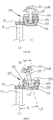
- FIGS 6A , 6B, and 7 illustrate an exemplary force receiving unit in the electronic imaging device.
- the force receiving unit 100 can engage with the developing unit 10 through a gear 15.
- the force receiving unit 100 includes an engaging portion 130, a force transmitting portion 150, and a position-limiter 600.
- the engaging portion 130 includes a projection 110 for engaging with the transmitting pin 510 of the driving unit (i.e., the projection thereof is provided with at least two projections), and transferring the rotational driving force to the connecting member 120.
- One end of the connecting member 120 is connected to the projection 110, and the other end of the connecting member 120 is disposed with the transferring member 125.
- the force transmitting portion 150 is provided with a transmission gear 152 for transferring a driving force, a cavity 155 in the center, and one or more chutes 151 on the side wall of the cavity 155.
- the various components may be assembled in certain ways.
- One end of the connecting member 120 i.e., the end with the transferring member 125
- the transferring member 125 abuts the chute 151 thereof to transfer the driving force
- the transmission gear 152 on the surface of the force transmitting portion 150 then transfers the driving force to the gear 15 of the developing unit 10, to drive the rotation of the developing unit 10.
- the engaging portion 130 can swing toward at least a certain direction in the force transmitting portion 150. That is, there is an inclination angle R1 between the center line L5 of the engaging portion 130 and the rotation axis of the force transmitting portion 150 or the rotation axis L3 of the developing unit 10, and the inclination range of the inclination angle R1 may be approximately between 5 degrees to 50 degrees.
- the position-limiter 600 disposed on the process cartridge C causes the engaging portion 130 to tilt toward the developing unit 10, and the center line L5 of the engaging portion 130 may remain constantly inclined to the rotation axis L4 of the force transmitting portion 150 or the rotation axis L3 of the developing unit 10. Because the engaging portion 130 remains at an inclined state, the distances between each one of the projections of the engaging portion 130 and the force transmitting portion 150 are different; that is, one projection is closer to the transmitting unit 150 than the other projection.
- the position-limiter 600 is a tensile spring. One end of the position-limiter 600 is attached to the connecting member 120, and the other end of the position-limiter 600 is attached to a protrusion or projection 81 of the position-limiter 80 (e.g., referring to Figure 5 ).
- the engaging portion 130 remains inclined due to the elastic force of the tensile spring.
- the position-limiter 600 may be a separate component disposed on the baffle 80, or the position-limiter 600 may also be a part of the baffle 80.
- the position-limiter 600 may include a blocking recess 650, and the blocking recess 650 abuts the connecting member 120 to cause the engaging portion 130 to remain in an inclined state constantly.
- the outer surface of the position-limiter 600 also has a slope 630. The slope 630 is able to abut the reverse side of the projection 110, also causing the engaging portion 130 to remain in an inclined state.
- the driving unit 500 moves in the longitudinal direction Y1.
- the engaging portion 130 remains in an inclined state constantly.
- the projection 110a of the engaging portion 130 which is closer to the force transmitting portion 150, can substantially avoid structural interference with the transmitting pin 510 moving together with the driving unit 500.
- the drive mechanism 500 can more easily enter the center position of the engaging portion 130.
- the driving unit 500 engages with the force receiving unit 100 to transfer the driving force, even when the distances between each of the projections (110a, 110b) and the force transmitting portion 150 are different, at least one transmitting pin 510 on the driving unit 500 can abut the projection 110b further from the force transmitting portion 150.
- the force receiving unit 100 remains inclined due to the restriction of the position-limiter 600. That is, the center line L5 of the engaging portion 130 remains inclined to the rotational axis L1 of the driving unit 500, and an inclination angle R2 exists between the center line L5 and the rotational axis L1.
- the drive assembly 100 may not need to be coaxial with the axial direction (i.e., L1, L2/L5) of the driving unit 500.
- the connecting member 120 of the engaging portion 130 also remains in the inclined state, when the force receiving unit 100 engages with the driving unit 500 at the other end of the connecting member 120, the rotation center of the force transmitting portion 150 is apart from the rotation center of the drive mechanism 500.
- the rotation axis L4 of the force transmitting portion 150 is apart from the rotation axis L1 of the driving unit 500 (i.e., there is a distance H2 in between), and the rotation axis L4 is substantially parallel to the rotation axis L1. If the force transmitting portion 150 and the gear 15 are separated from each other due to the distance H2, an additional gear may be added between the force transmitting portion 150 and the gear 15, or the size of the gear 15 may also be adjusted.
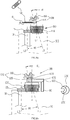
- the projection 110 of the engaging portion 130 may be replaced by a bowl-shaped body 160 having an inner recess.
- the bowl-shaped body 160 is disposed at one end of the connecting member 120 in the same manner as the projection 110.
- the bowl-shaped 160 has a concave opening 165, and the opening 165 has at least two blocking walls 161.
- the concave opening 165 enclaves or fittingly wraps the circular arc projection 515 at the front side of the driving unit 500 (e.g., Figure 11a ), and the blocking wall 161 is disposed to abut the transmitting pin 510 of the driving unit 500 to receive the driving force.
- the bowl-shaped body 160 is restricted by the position-limiter 600, and the center line L5 of the bowl-shaped body 160 remains inclined with respect to the rotation axis L4 of the transmission unit 150 or the rotation axis L1 of the driving unit 500.
- the driving unit 500 moves along the longitudinal direction Y1 into the bowl-shaped body 160 of the engaging portion 130, and the transmitting pin 510 of the driving unit 500 transfers the driving force by abutting one blocking wall 160 on the bowl-shaped body 160. Due to the shape configuration of the bowl-shaped body 160, during the transfer of the driving force, the arc projection 515 of the driving unit 500 is enclaved by the bowl-shaped 160, and the transmitting pin 510 also abuts the blocking wall 161 in the opening 165. Accordingly, when the driving unit 500 engages with the force receiving unit 100 to transfer the driving force, the driving unit 500 and the engaging portion 130 can largely avoid disengagement.
- the connecting member 120 of the engaging portion 130 may be a cylindrical rod, or an elastic member (i.e., a tensile spring) connecting the projection 110 and the transmitting unit 150.
- an elastic member i.e., a tensile spring
- 150 by replacing the connecting rod with the elastic member, the transferring member 125 of the connecting member 120, and the cavity 155 and chutes 151 of the force transmitting portion 150 may be omitted.
- a simple process e.g., gluing, buckling, or riveting, may be used to connect the elastic member with the projection 110 and the force transmitting portion 150.
- the position-limiter 600 may have a blocking recess 650 and may abut the connecting member 120 or the reverse side of the projection 110, causing the engaging portion 130 to maintain the inclined state. That is, the center line L5 of engaging portion 130 constantly remains inclined with respect to the rotation axis L4 of the force transmitting portion 150 or the rotation axis L3 of the developing unit 10.
- the projection 110 of the engaging portion 130 can also be replaced by the bowl-shaped body 160 shown in Figure 10 .
- the engaging portion 130 remains inclined when engaging with the transmitting pin 510 of the driving unit 500, two or more projections 110 on the engaging portion 130 or two or more blocking walls 161 in the bowl-shaped body 160 may be provided.
- the transmitting pin 510 can more easily abut the projection 110 or the blocking wall 161 to transfer the driving force.
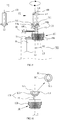
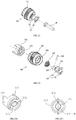
- Figures 14 and 15 illustrate another exemplary force receiving unit of the process cartridge C.
- the force receiving unit 200 includes an engaging portion 230, a force transmitting portion 250, a position-limiter 600, and a base 270.
- the position-limiter 600 may be a tensile spring and, in one embodiment, may be a conical tensile spring.
- a base 270 is provided with a cavity 275 on one end; one or more chute 276 is provided on the side of the cavity 275; and a positioning protrusion 272 is provided on the cylindrical side-surface of the base 270.
- the cavity 275 is located at an offset from the central axis of the base 270. That is, the center point A1' of the cavity 275 is at an offset from the rotation central axis A1 of the base 270, and a distance D1 exists between the center point A1' and the rotation central axis A1, which may be in a range of approximately 2mm to 8mm.
- an opening 255 and a blocking protrusion 257 are disposed on one end of the force transmitting portion 250; a recess 256 is disposed next to the opening 255, and a positioning hole 252 is situated on the cylindrical surface of the force transmitting portion 250.
- the opening 255 is not centered on the central axis of the force transmitting portion 250. That is, the center point A2' of the opening 255 is at an offset from the rotation central axis L4 of the force transmitting portion 250.
- a distance D1 exists between the center point A2' and the rotation central axis L4 exists, and may be in a ranges from approximately 2mm to 8mm.
- the engaging portion 230 includes a projection 210 and a connecting member 220.
- the connecting member 220 is connected to the projection 210 at one end, and includes a sphere body 225 at the other end.
- the connecting member 220 may also include a blocking layer 222.
- the various components may be assembled in certain ways. As shown in Figures 15 to 20 , the sphere body 225 of the engaging portion 230 passes through the position-limiter 600 and a transferring member 226 is assembled into the sphere body 225. The sphere body 225 and the transferring member 226 pass through the opening 255 and the recess 256 of the force transmitting portion 250. The sphere body 225 at one end of the connecting member 220 is placed into the cavity 275, and the transferring member 226 is located in the chute 276.
- the base 270 is fixed on the force transmitting portion 250, through the positioning protrusion 272 locked to the positioning hole 252.
- the connecting member 220 passes through the position-limiter 600, and the connecting member 220 is disposed between the end surface 251a and the blocking layer 222. Because the opening 255 is structurally deviated from the cavity 275, when coupling the force transmitting portion 250 with the base 270, the center point A2' needs to be coaxially aligned with the center point A1'.
- the opening 255 may substantially overlap with the cavity 275, while the recess 256 and the chute 276 may not substantially overlap or do not overlap. Accordingly, after the transferring member 226 of the sphere body 225 is placed into the chute 276, the transferring member 226 may be confined in the chute 276, so as to prevent engaging portion 230 from disengaging from the force transmitting portion 250.
- the position-limiter 600 abutting the end surface 251a may also remain inclined.
- the engaging portion 230 may also be tilted, and the center line L5 of the engaging portion 230 remains inclined with respect to the rotation axis L4 of the force transmitting portion 250.
- the elastic property of the position-limiter 600 may cause the engaging portion 230 to retreat inwardly when being compressed, and to extend outwardly when not being compressed.
- a blocking or retaining projection 257 may be disposed on the end surface of the force transmitting portion 250. The retaining projection 257 may prevent the position-limiter 600 from separating from the end surface 251a.
- the engagement process of the force receiving unit 200 with the driving unit 500 may be similar to those described above, for example, as shown in Figures 9 , 11A and 13 .
- the center line L5 of the assembled engaging portion 230 is at an offset position with respect to the rotation axis L4 of the force transmitting portion 250.
- the position-limiter 600 not only can cause the engaging portion 230 to constantly remain inclined with respect to the force transmitting portion 250, but also can cause the entire engaging portion 230 to retreat inwardly relative to the force transmitting portion 250 ( Figure 21A ) when under pressure due to a certain probability that the projection 210 structurally interferes with the transmitting pin 510.
- the rotating transmitting pin 510 can contact with the engagement claws in a staggered format.
- the projection 210 is not under pressure, and the engaging portion 230 receives an elastic force from the position-limiter 600 and extends outwardly. Finally, the projection 210 contacts and engages the transmitting pin 510 to receive the rotational driving force ( Figure 21B ).
- the center line L5 remains constantly inclined with respect to the rotation axis L1 of the driving unit 500 or the rotation axis L4 of the force transmitting portion 250.
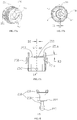
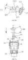
- Figures 22 and 23 illustrate another exemplary force receiving unit of the process cartridge C.
- the force receiving unit 300 includes an engaging portion 330, a force transmitting portion 350, a position-limiter 600, and a base 370.
- the position-limiter 600 is a tensile spring, and the tensile spring may be in a conical shape.
- the center point A10' of the cavity 375 on the end surface is substantially coaxial with the rotation center A1 of the base 370 ( Figure 24B ); and the chute 376 and the positioning protrusion 372 may be disposed in similar ways as described in the second embodiment.
- the center point A20' of the opening 355 on the end surface is substantially coaxial with the rotation axis L4 of the force transmitting portion 350; and the recess 356, positioning hole 352 and blocking protrusion 357 may be disposed in similar ways as described in the second embodiment.
- the engaging portion 330 includes a projection 310 and a connecting member 320.
- the connecting member 320 is connected to the projection 310 at one end and is provided with a sphere 325 at the other end.
- the connecting member may also be disposed with a blocking layer 322.
- the center line L5 of the engaging portion 330 is deviated from the center line L5a of the sphere 325 on one end of the connecting member 320, and a distance D3 exists between the center line L5 and the center line L5a, which may be in a ranges of approximately 2mm to 8mm.
- one side 320a of the connecting member 320 is outwardly higher (i.e., along the Y' axis) than one side 325b of the sphere 325, and a distance H3 exists between the side 320a and the side 325a.
- the diameter H5 of the opening 355 is larger than or equal to the diameter H4 of the sphere 325, the diameter H4 of the sphere 325 plus the total length of the distance H3 is larger than the diameter H5 of the opening 355, and the diameter H5 of the opening 355 is substantially equal to the diameter of the cavity 375.
- the various components may be assembled in certain ways. As shown from Figures 23 to 29 , the sphere 325 of the engaging portion 330 passes through the position-limiter 600, and the transferring member 326 is assembled into the sphere 325. The sphere 325 and the transferring member 326 pass through the opening 355 and the recess 356 of the force transmitting portion 350. The sphere 325 at one end of the connecting member 320 is placed into the cavity 375, and the transferring member 326 is located in the chute 376.
- the base 370 is fixed on the force transmitting portion 350.
- the position-limiter 600 is passed through by the connecting member 320, and is situated between the transferring surface 350 and the blocking layer 322. Because the diameter H5 of the opening 355 is greater than or equal to the diameter H4 of the sphere 325, the sphere 325 can smoothly passes through the opening 355 and can be assembled inside the cavity 375 ( Figure 27A ).
- the side 320a is restricted by the diameter size of the opening 355, causing the engaging portion 330 to remain inclined with respect to the force transmitting portion 350. That is, the center line L5 of the engaging portion 330 is inclined with respect to the rotation axis L4 of the force transmitting portion 350 ( Figure 27B ).
- the engaging portion 330 remains at a predetermined inclination angle.
- the engaging portion 330 reaches a minimum inclination angle with respect to the force transmitting portion 350.
- the engaging portion 330 may retreat or extend with respect to the force transmitting portion 350, as similarly described in the second embodiment.
- an engaging portion 430 includes a projection 410 and a connecting member 420.
- the connecting member 420 is connected to the projection 410 at one end and is disposed with a sphere 325 at the other end, and a baffle 422 may also be disposed on the connecting member 420.
- the engaging portion 430 is an arc-shaped structure, and the center line L6 of the engaging portion 430 is not a straight line, rather having a certain degree of curving or arc.
- the arc-shaped engaging portion 430 can achieve the same effect through the inclination angle between the engaging portion (130/230/330) and the force transmitting portion (150/250/350) as illustrated in the third, fourth, and third embodiments, such that the driving unit 500 can be easily entered into the center of the engaging portion 430 and the rotating transmitting pin 510 can abut the projection 410 to transfer the driving force.
- the structural dispositions and installations of the engaging portion (i.e., 230/330/430) in the second, third and fourth embodiments are different from the structural disposition and installation of the engaging portion 330 in the first embodiment.
- the axis or center line (i.e., L5/L6) of the engaging portion (i.e., 230/ 330/430) and the rotation axis L4 of the force transmitting portion (i.e., 250/350) intersect at a point X1 outside the end surface of the force transmitting portion (i.e., 250/350).
- the center line (L5) of the engaging portion i.e., 230 / 330
- the center axis L4 of the force transmitting portion i.e., 250 / 350.
- the center axis L5 of the engaging portion 130 and the rotation axis L4 of the power transfer 150 may intersect at a point X2 inside the force transmitting portion 150 in the first embodiment.
- the structural disposition of the position-limiter 600 in the second, third, and fourth embodiments are different.
- the position-limiter 600 is situated in the engaging portion 130 at one end and in the baffle 80 or the housing of the process cartridge C at the other end; while in the fourth, fifth and fourth embodiments, the position-limiter 600 can be disposed in the force receiving unit 200/300. This way, the operation can be facilitated, the operation length can be shortened, and the procedures can be reduced.
- the force receiving unit 100/200/300 and the driving unit 500 may detach from each other, and the drive mechanism 500 moves in the opposite direction to the longitude direction Y1. Because the engaging portion 130/230/330 of the force receiving unit 100/200/300 remain in the inclined state with respect to the force transmitting portion 150/250/350, the driving unit 500 can easily detach from the engaging portion 130/230/330, and the transmitting pin 510 of the driving unit 500 does not substantially interfere with projection 110/210/310 or the blocking wall 161 (similarly with the arc-shaped engaging portion 430).
- the engaging portion of the force receiving unit engages the driving unit in the electronic imaging device or after the engaging portion of the force receiving unit engages the driving unit in the electronic imaging device to transfer the driving force, the engaging portion of the force receiving unit remains constantly inclined with respect to the force transmitting portion, the driving unit, or the developing unit of the force receiving unit.
- the present invention not only overcomes the structural interference occurred in the engagement or disengagement of the force receiving unit with the driving unit, but also maintains structural strength even after multiple engagement and disengagement, avoiding the structural tear or breaking and improving the service life of the process cartridge or the electronic imaging device.
Landscapes
- Engineering & Computer Science (AREA)
- Computer Vision & Pattern Recognition (AREA)
- Physics & Mathematics (AREA)
- General Physics & Mathematics (AREA)
- Electrophotography Configuration And Component (AREA)
- Casings For Electric Apparatus (AREA)
- Ink Jet (AREA)
Applications Claiming Priority (3)
| Application Number | Priority Date | Filing Date | Title |
|---|---|---|---|
| CN201410188674 | 2014-05-06 | ||
| CN201410321331.5A CN105093871B (zh) | 2014-05-06 | 2014-07-07 | 一种动力接收单元及处理盒 |
| PCT/CN2015/078260 WO2015169205A1 (zh) | 2014-05-06 | 2015-05-05 | 一种动力接收单元及处理盒 |
Publications (2)
| Publication Number | Publication Date |
|---|---|
| EP3141965A1 true EP3141965A1 (de) | 2017-03-15 |
| EP3141965A4 EP3141965A4 (de) | 2017-12-27 |
Family
ID=54392146
Family Applications (1)
| Application Number | Title | Priority Date | Filing Date |
|---|---|---|---|
| EP15788964.3A Withdrawn EP3141965A4 (de) | 2014-05-06 | 2015-05-05 | Kraftaufnahmeeinheit und -verarbeitungskasten |
Country Status (3)
| Country | Link |
|---|---|
| EP (1) | EP3141965A4 (de) |
| CN (1) | CN105093871B (de) |
| WO (1) | WO2015169205A1 (de) |
Families Citing this family (3)
| Publication number | Priority date | Publication date | Assignee | Title |
|---|---|---|---|---|
| CN105242511B (zh) * | 2015-11-17 | 2022-04-19 | 珠海天威飞马打印耗材有限公司 | 齿轮座、驱动组件和处理盒 |
| WO2017084412A1 (zh) * | 2015-11-21 | 2017-05-26 | 珠海艾派克科技股份有限公司 | 一种处理盒、以及包含该处理盒的图像形成装置 |
| CN205899249U (zh) * | 2016-05-25 | 2017-01-18 | 珠海艾派克科技股份有限公司 | 一种处理盒的驱动组件及包含该驱动组件的处理盒 |
Family Cites Families (11)
| Publication number | Priority date | Publication date | Assignee | Title |
|---|---|---|---|---|
| JP3689504B2 (ja) * | 1996-09-26 | 2005-08-31 | キヤノン株式会社 | 電子写真画像形成装置 |
| JP2004045603A (ja) * | 2002-07-10 | 2004-02-12 | Konica Minolta Holdings Inc | 画像形成装置 |
| JP4498407B2 (ja) * | 2006-12-22 | 2010-07-07 | キヤノン株式会社 | プロセスカートリッジ、電子写真画像形成装置、及び、電子写真感光体ドラムユニット |
| JP4558083B2 (ja) * | 2008-06-20 | 2010-10-06 | キヤノン株式会社 | カートリッジ、前記カートリッジの組立て方法、及び、前記カートリッジの分解方法 |
| JP4803267B2 (ja) * | 2009-02-17 | 2011-10-26 | 富士ゼロックス株式会社 | 画像形成装置 |
| JP5344580B2 (ja) * | 2009-02-27 | 2013-11-20 | キヤノン株式会社 | カートリッジ及び電子写真画像形成装置 |
| CN103376683B (zh) * | 2012-04-25 | 2016-01-13 | 上福全球科技股份有限公司 | 感光鼓的传动组件 |
| JP5943716B2 (ja) * | 2012-06-04 | 2016-07-05 | キヤノン株式会社 | 現像カートリッジ |
| CN203573085U (zh) * | 2013-09-29 | 2014-04-30 | 珠海凯威置业有限公司 | 一种旋转力驱动组件以及处理盒 |
| CN204009372U (zh) * | 2014-07-02 | 2014-12-10 | 珠海赛纳打印科技股份有限公司 | 一种动力接收单元及处理盒 |
| CN204009361U (zh) * | 2014-05-06 | 2014-12-10 | 珠海赛纳打印科技股份有限公司 | 一种动力接收单元及处理盒 |
-
2014
- 2014-07-07 CN CN201410321331.5A patent/CN105093871B/zh active Active
-
2015
- 2015-05-05 WO PCT/CN2015/078260 patent/WO2015169205A1/zh not_active Ceased
- 2015-05-05 EP EP15788964.3A patent/EP3141965A4/de not_active Withdrawn
Non-Patent Citations (1)
| Title |
|---|
| See references of WO2015169205A1 * |
Also Published As
| Publication number | Publication date |
|---|---|
| WO2015169205A1 (zh) | 2015-11-12 |
| CN105093871B (zh) | 2017-12-29 |
| EP3141965A4 (de) | 2017-12-27 |
| CN105093871A (zh) | 2015-11-25 |
Similar Documents
| Publication | Publication Date | Title |
|---|---|---|
| US9846409B2 (en) | Processing cartridge and driving assembly thereof | |
| CN111505924A (zh) | 作用机构以及驱动组件和显影盒 | |
| CN106200297B (zh) | 旋转力驱动组件及处理盒 | |
| JP3191130U (ja) | 電子写真感光体 | |
| RU2014115669A (ru) | Деталь, передающая вращательное усилие | |
| EP3141965A1 (de) | Kraftaufnahmeeinheit und -verarbeitungskasten | |
| WO2015005446A1 (ja) | 軸受部材、端部部材、感光体ドラムユニット、現像ローラユニット、プロセスカートリッジ、中間部材、及び軸受部材の本体 | |
| CN105589318B (zh) | 一种处理盒用驱动组件、感光鼓单元、处理盒及图像形成装置 | |
| US20170176914A1 (en) | Photosensitive drum driving component and a cartridge comprising the same | |
| JP4419604B2 (ja) | 画像形成装置 | |
| CN107544225B (zh) | 一种显影盒 | |
| CN103885306B (zh) | 驱动组件、辊和处理盒 | |
| CN107436551B (zh) | 一种处理盒的驱动组件及包含该驱动组件的处理盒 | |
| EP3467593B1 (de) | Antriebskraftempfangsanordnung und verarbeitungskammer mit der anordnung | |
| CN108153128B (zh) | 动力传递装置以及处理盒 | |
| CN116300361A (zh) | 处理盒和成像设备 | |
| CN107219736B (zh) | 旋转力传递组件和处理盒 | |
| US9152126B2 (en) | Driving force transmission mechanism for image forming apparatus and processing cartridge | |
| CN107561890B (zh) | 一种显影盒 | |
| CN110727191A (zh) | 一种处理盒 | |
| CN107632502A (zh) | 一种显影盒 | |
| CN104035302B (zh) | 一种显影盒 | |
| CN109001966B (zh) | 处理盒 | |
| CN207366937U (zh) | 一种显影盒 | |
| CN216351791U (zh) | 一种处理盒的驱动组件及处理盒 |
Legal Events
| Date | Code | Title | Description |
|---|---|---|---|
| PUAI | Public reference made under article 153(3) epc to a published international application that has entered the european phase |
Free format text: ORIGINAL CODE: 0009012 |
|
| 17P | Request for examination filed |
Effective date: 20161122 |
|
| AK | Designated contracting states |
Kind code of ref document: A1 Designated state(s): AL AT BE BG CH CY CZ DE DK EE ES FI FR GB GR HR HU IE IS IT LI LT LU LV MC MK MT NL NO PL PT RO RS SE SI SK SM TR |
|
| AX | Request for extension of the european patent |
Extension state: BA ME |
|
| DAV | Request for validation of the european patent (deleted) | ||
| DAX | Request for extension of the european patent (deleted) | ||
| RAP1 | Party data changed (applicant data changed or rights of an application transferred) |
Owner name: NINESTAR CORPORATION |
|
| A4 | Supplementary search report drawn up and despatched |
Effective date: 20171124 |
|
| RIC1 | Information provided on ipc code assigned before grant |
Ipc: G03G 21/18 20060101AFI20171120BHEP Ipc: G03G 15/00 20060101ALI20171120BHEP |
|
| STAA | Information on the status of an ep patent application or granted ep patent |
Free format text: STATUS: THE APPLICATION IS DEEMED TO BE WITHDRAWN |
|
| 18D | Application deemed to be withdrawn |
Effective date: 20180623 |