EP3142045B1 - Vorhersage der genauigkeit von objekterkennung in einem zusammengesetzten bild - Google Patents
Vorhersage der genauigkeit von objekterkennung in einem zusammengesetzten bild Download PDFInfo
- Publication number
- EP3142045B1 EP3142045B1 EP15199566.9A EP15199566A EP3142045B1 EP 3142045 B1 EP3142045 B1 EP 3142045B1 EP 15199566 A EP15199566 A EP 15199566A EP 3142045 B1 EP3142045 B1 EP 3142045B1
- Authority
- EP
- European Patent Office
- Prior art keywords
- image
- images
- object recognition
- processing device
- image processing
- Prior art date
- Legal status (The legal status is an assumption and is not a legal conclusion. Google has not performed a legal analysis and makes no representation as to the accuracy of the status listed.)
- Active
Links
Images




Classifications
-
- G—PHYSICS
- G06—COMPUTING OR CALCULATING; COUNTING
- G06T—IMAGE DATA PROCESSING OR GENERATION, IN GENERAL
- G06T3/00—Geometric image transformations in the plane of the image
- G06T3/40—Scaling of whole images or parts thereof, e.g. expanding or contracting
- G06T3/4038—Image mosaicing, e.g. composing plane images from plane sub-images
-
- G—PHYSICS
- G06—COMPUTING OR CALCULATING; COUNTING
- G06T—IMAGE DATA PROCESSING OR GENERATION, IN GENERAL
- G06T7/00—Image analysis
- G06T7/0002—Inspection of images, e.g. flaw detection
-
- G—PHYSICS
- G06—COMPUTING OR CALCULATING; COUNTING
- G06F—ELECTRIC DIGITAL DATA PROCESSING
- G06F18/00—Pattern recognition
- G06F18/20—Analysing
- G06F18/21—Design or setup of recognition systems or techniques; Extraction of features in feature space; Blind source separation
- G06F18/217—Validation; Performance evaluation; Active pattern learning techniques
-
- G—PHYSICS
- G06—COMPUTING OR CALCULATING; COUNTING
- G06F—ELECTRIC DIGITAL DATA PROCESSING
- G06F18/00—Pattern recognition
- G06F18/20—Analysing
- G06F18/24—Classification techniques
- G06F18/241—Classification techniques relating to the classification model, e.g. parametric or non-parametric approaches
- G06F18/2415—Classification techniques relating to the classification model, e.g. parametric or non-parametric approaches based on parametric or probabilistic models, e.g. based on likelihood ratio or false acceptance rate versus a false rejection rate
-
- G—PHYSICS
- G06—COMPUTING OR CALCULATING; COUNTING
- G06T—IMAGE DATA PROCESSING OR GENERATION, IN GENERAL
- G06T5/00—Image enhancement or restoration
- G06T5/50—Image enhancement or restoration using two or more images, e.g. averaging or subtraction
-
- G—PHYSICS
- G06—COMPUTING OR CALCULATING; COUNTING
- G06V—IMAGE OR VIDEO RECOGNITION OR UNDERSTANDING
- G06V10/00—Arrangements for image or video recognition or understanding
- G06V10/20—Image preprocessing
- G06V10/30—Noise filtering
-
- G—PHYSICS
- G06—COMPUTING OR CALCULATING; COUNTING
- G06V—IMAGE OR VIDEO RECOGNITION OR UNDERSTANDING
- G06V10/00—Arrangements for image or video recognition or understanding
- G06V10/40—Extraction of image or video features
- G06V10/56—Extraction of image or video features relating to colour
-
- G—PHYSICS
- G06—COMPUTING OR CALCULATING; COUNTING
- G06V—IMAGE OR VIDEO RECOGNITION OR UNDERSTANDING
- G06V10/00—Arrangements for image or video recognition or understanding
- G06V10/70—Arrangements for image or video recognition or understanding using pattern recognition or machine learning
-
- G—PHYSICS
- G06—COMPUTING OR CALCULATING; COUNTING
- G06V—IMAGE OR VIDEO RECOGNITION OR UNDERSTANDING
- G06V10/00—Arrangements for image or video recognition or understanding
- G06V10/70—Arrangements for image or video recognition or understanding using pattern recognition or machine learning
- G06V10/764—Arrangements for image or video recognition or understanding using pattern recognition or machine learning using classification, e.g. of video objects
-
- G—PHYSICS
- G06—COMPUTING OR CALCULATING; COUNTING
- G06V—IMAGE OR VIDEO RECOGNITION OR UNDERSTANDING
- G06V10/00—Arrangements for image or video recognition or understanding
- G06V10/70—Arrangements for image or video recognition or understanding using pattern recognition or machine learning
- G06V10/77—Processing image or video features in feature spaces; using data integration or data reduction, e.g. principal component analysis [PCA] or independent component analysis [ICA] or self-organising maps [SOM]; Blind source separation
- G06V10/776—Validation; Performance evaluation
-
- G—PHYSICS
- G06—COMPUTING OR CALCULATING; COUNTING
- G06V—IMAGE OR VIDEO RECOGNITION OR UNDERSTANDING
- G06V10/00—Arrangements for image or video recognition or understanding
- G06V10/98—Detection or correction of errors, e.g. by rescanning the pattern or by human intervention; Evaluation of the quality of the acquired patterns
- G06V10/993—Evaluation of the quality of the acquired pattern
-
- G—PHYSICS
- G06—COMPUTING OR CALCULATING; COUNTING
- G06T—IMAGE DATA PROCESSING OR GENERATION, IN GENERAL
- G06T2207/00—Indexing scheme for image analysis or image enhancement
- G06T2207/30—Subject of image; Context of image processing
- G06T2207/30168—Image quality inspection
-
- G—PHYSICS
- G06—COMPUTING OR CALCULATING; COUNTING
- G06V—IMAGE OR VIDEO RECOGNITION OR UNDERSTANDING
- G06V10/00—Arrangements for image or video recognition or understanding
- G06V10/10—Image acquisition
- G06V10/16—Image acquisition using multiple overlapping images; Image stitching
-
- G—PHYSICS
- G06—COMPUTING OR CALCULATING; COUNTING
- G06V—IMAGE OR VIDEO RECOGNITION OR UNDERSTANDING
- G06V10/00—Arrangements for image or video recognition or understanding
- G06V10/20—Image preprocessing
- G06V10/32—Normalisation of the pattern dimensions
-
- G—PHYSICS
- G06—COMPUTING OR CALCULATING; COUNTING
- G06V—IMAGE OR VIDEO RECOGNITION OR UNDERSTANDING
- G06V10/00—Arrangements for image or video recognition or understanding
- G06V10/20—Image preprocessing
- G06V10/34—Smoothing or thinning of the pattern; Morphological operations; Skeletonisation
Definitions
- An image capture device such as a camera, a mobile phone that includes a camera, or the like, may capture a set of images with some overlap between images of the set of images.
- the set of images may be combined, or stitched, into a stitched image based on the overlap between the images, to capture an image of a wide area at a higher resolution than the resolutions of each individual image.
- a device may perform an object recognition operation to detect objects in the stitched image.
- the stitched image may show a store shelf, and the device may perform an object recognition operation to determine which products are stocked on the store shelf.
- US 2008/0306787 (Hamilton ) describes a method for measuring retail store display compliance. Images of retail store conditions are captured and associated with related information. The captured images and the related information are transmitted to a processing location. The retail store conditions in the captured images are compared with a library to identify them.
- the invention provides a device, a method, a computer program product and a computer system, as defined in the appended claims.
- a device may include one or more processors.
- the device receives a set of images for an object recognition operation.
- the object recognition operation identifies one or more objects in the set of images after the set of images are combined into a stitched image.
- the device combines the set of images into the stitched image.
- the device determines one or more reliability scores for the set of images.
- the one or more reliability scores are determined based on a difference in a color parameter of two or more images of the set of images, and the one or more reliability scores predicts a quality of the stitched image that includes an image, of the set of images, to which the one or more reliability score corresponds.
- the device determines whether a result of the object recognition operation is likely to satisfy a threshold based on the one or more reliability scores.
- the device selectively performs the object recognition operation based on whether the result of the object recognition operation is likely to satisfy the threshold.
- the one or more processors when determining whether the result of the object recognition operation is likely to satisfy the threshold, are to determine whether the result of the object recognition operation is likely to satisfy the threshold based on a predictive model. Accordingly, the predictive model may output a likelihood of the result of the object recognition operation satisfying the threshold based on the one or more reliability scores.
- the one or more processors may update the predictive model based on:
- the one or more processors when determining the one or more reliability scores, generate a composite image based on two or more images of the plurality of images Accordingly, the composite image is generated based on differences at corresponding points in a first image and a second image of the plurality of images.
- the differences include differences between the corresponding points in the first image and the second image, in at least one of a hue parameter, a saturation parameter, or a value parameter.
- the one or more processors when determining the one or more reliability scores, determine a reliability score for the first image and the second image based on at least one of a mean of hue parameters of a plurality of points in the composite image, a mean of saturation parameters of a plurality of points in the composite image, or a mean of value parameters of a plurality of points in the composite image.
- the one or more processors when determining the one or more reliability scores, may perform at least one morphological operation on the composite image.
- the morphological operation may include at least one of the following:
- the one or more processors when determining the one or more reliability scores may perform a filtering operation on the first image and the second image to reduce noise in the first image and the second image.
- the filtering operation may include one or more of:
- the one or more processors when determining the one or more reliability scores, may determine a plurality of reliability scores corresponding to the plurality of images.
- the disclosed subject matter may be implemented as a computer program product.
- the computer program product may be a (possibly non-transitory) computer-readable medium storing instructions.
- the non-transitory computer-readable medium stores one or more instructions that, when executed by one or more processors, cause the one or more processors to receive a set of images for an object recognition operation.
- the object recognition operation identifies one or more objects in the set of images after the set of images are combined into a stitched image.
- the one or more instructions when executed by the one or more processors, cause the one or more processors to combine the set of images into the stitched image.
- the one or more instructions when executed by the one or more processors, cause the one or more processors to determine one or more reliability scores for the set of images.
- the one or more reliability scores are determined based on a difference at corresponding points of two or more images of the set of images, and the one or more reliability scores reflect a quality of a stitched image that includes an image, of the set of images, to which the one or more reliability scores corresponds.
- the one or more instructions when executed by the one or more processors, cause the one or more processors to determine that the object recognition operation is likely to satisfy a threshold based on the one or more reliability scores.
- the one or more instructions when executed by the one or more processors, cause the one or more processors to perform the object recognition operation based on the object recognition operation being likely to satisfy the threshold.
- the one or more reliability scores include a plurality of reliability scores corresponding to the plurality of images.
- the one or more instructions may also cause the one or more processors to combine the plurality of reliability scores by determining at least one of:
- the one or more instructions, that cause the one or more processors to determine the one or more reliability scores also cause the one or more processors to determine an overlapped area of a first image and a corresponding overlapped area of a second image.
- the plurality of images include the first image and the second image.
- the one or more instructions may further cause the one or more processors to determine a first mean luminosity corresponding to the overlapped area of the first image and a second mean luminosity corresponding to the overlapped area of the second image.
- the one or more instructions may further cause the one or more processors change a luminosity of the overlapped area in the first image and the overlapped area of the second image to a third mean luminosity.
- the third mean luminosity may be determined based on combining the first mean luminosity and the second mean luminosity.
- the one or more instructions, that cause the one or more processors to combine the plurality of images may also cause the one or more processors to determine a plurality of homography matrices corresponding to the plurality of images.
- the plurality of homography matrices may provide parameters for projecting the plurality of images onto a common plane.
- the one or more instructions may also cause the one or more processors to project the plurality of images onto the common plane based on the plurality of homography matrices.
- the one or more instructions when executed by the one or more processors, may cause the one or more processors to convert the plurality of images to a hue-saturation-value color space.
- the one or more instructions, that cause the one or more processors to determine the one or more reliability scores cause the one or more processors to determine a composite image based on a pair of images of the plurality of images.
- the composite image being determined based on combining at least one of:
- the one or more instructions when executed by the one or more processors, may cause the one or more processors to provide information indicating that the object recognition operation is likely to satisfy the threshold.
- the one or more instructions, that cause the one or more processors to perform the object recognition operation cause the one or more processors to receive an instruction to perform the object recognition operation based on providing the information indicating that the object recognition operation is likely to satisfy the threshold.
- a (computer-implemented) method includes receiving a stitched image for an object recognition operation.
- the stitched image includes a set of images.
- the object recognition operation identifies one or more objects in the stitched image.
- the method may include obtaining the set of images.
- the method includes determining one or more reliability scores for the set of images.
- the one or more reliability scores are determined based on a difference at corresponding points of two or more images of the set of images.
- the one or more reliability scores correspond to a quality of the stitched image that includes an image, of the set of images, to which the one or more reliability scores correspond.
- the method includes determining that a result of the object recognition operation is likely to satisfy a threshold based on the one or more reliability scores.
- the method includes performing the object recognition operation based on the result of the object recognition operation being likely to satisfy the threshold.
- Determining the one or more reliability scores may comprise determining at least two reliability scores for a particular image of the plurality of images.
- the particular image may overlap at least two other images, of the plurality of images, in the stitched image.
- the method may further comprise combining the at least two reliability scores for the particular image to determine a final reliability score for the particular image.
- the final reliability score may be one of the one or more reliability scores for the plurality of images.
- the method may further comprise identifying the one or more objects based on the object recognition operation, and providing information identifying the one or more objects.
- Determining the one or more reliability scores comprises generating a composite image based on two or more images of the plurality of images.
- the composite image is generated based on differences at corresponding points in a first image and a second image of the plurality of images.
- the differences include differences between the corresponding points in the first image and the second image, in at least one of a hue parameter, a saturation parameter, or a value parameter.
- the method further comprises determining a reliability score for the first image and the second image based on at least one of:
- the method further comprises providing information indicating that the result of the object recognition operation is likely to satisfy the threshold.
- Performing the object recognition operation comprises receiving an instruction to perform the object recognition operation based on providing the information indicating that the result of the object recognition operation is likely to satisfy the threshold, and performing the object recognition operation based on the instruction.
- Determining that the result of the object recognition operation is likely to satisfy the threshold comprises determining that the result of the object recognition operation is likely to satisfy the threshold based on a predictive model.
- the predictive model outputs a likelihood of the result of the object recognition operation satisfying the threshold based on the one or more reliability scores.
- An image capture device may capture a set of images. Some images, of the set of images, may share an overlapped area. For example, the set of images may be arranged in a grid, and adjacent images in the grid may overlap each other.
- the image capture device, or an image processing device may combine, or stitch, the set of images into a single, stitched image. For example, the image capture device may locate common elements in overlaps between two images, may project the two images onto a common plane, and may align the common elements to overlap the images into a stitched image.
- the image processing device may analyze the stitched image to identify objects in the stitched image. For example, the image processing device may identify inventory products in a stitched image of a store shelf, may identify identities of persons in a stitched image of a crowd, may identify cars in a stitched image of a parking lot, or the like.
- the image processing device may require a stitched image of a particular quality to identify the objects. For example, the image processing device may require a particular resolution of the stitched image, may require a stitched image that is not blurry, or the like. However, determining whether the stitched image is of the particular quality may be difficult for a user of the image capture device.
- Implementations described herein enable the image processing device to predict a result of the object recognition operation based on reliability scores for the set of images. Based on the reliability scores, the image processing device or another device (e.g., a client device, based on a user input) may determine whether to proceed with the object recognition operation. In this way, the image processing device conserves processor and memory resources and improves accuracy of object recognition, which saves time and money for the organization implementing the object recognition operation.
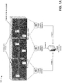
- Figs. 1A and 1B are diagrams of an overview of an example implementation 100 described herein.
- a set of image capture devices e.g., image capture device 1, image capture device 2, and image capture device 3 may capture images of objects on a shelf.
- the images captured by the set of image capture devices may share some overlap.
- image 1 and image 2 share an overlap that includes one object
- image 2 and image 3 share an overlap that includes two objects.
- image capture device 1, image capture device 2, and image capture device 3 may provide image 1, image 2, and image 3 to an image processing device.
- the image processing device may stitch image 1, image 2, and image 3 into a stitched image. Assume that the stitched image shows each of the products captured in image 1, image 2, and image 3. As further shown, the image processing device may determine reliability scores for each of image 1, image 2, and image 3. The image processing device may determine the reliability scores based on differences between images in the overlapped areas of the images. For example, the image processing device may determine a reliability score for image 1 based on differences between image 1 and image 2 with regard to the overlapped area between image 1 and image 2.
- the image processing device may determine a reliability score for image 2 based on differences between image 1 and image 2 with regard to the overlapped area between image 1 and image 2, and based on differences between image 2 and image 3 with regard to the overlapped area between image 2 and image 3.
- the image processing device may determine that an object recognition operation is likely to be successful (e.g., likely to identify a threshold quantity of objects, likely to identify a threshold ratio of objects included in the stitched image, etc.) for the stitched image. As shown, the image processing device may determine that the object recognition operation is likely to be successful based on a predictive model.
- the predictive model may output a predicted likelihood that the object recognition operation is likely to be successful based on an input of a set of reliability scores, and may be trained based on known results of object recognition operations and past reliability scores.
- the image processing device may provide object recognition results and the stitched image to a client device.
- the image processing device 210 may update the predictive model based on the object recognition results and based on the reliability scores to improve the predictive model. In this way, the image processing device predicts whether the object recognition operation is likely to be successful, which conserves processor and memory resources and improves accuracy of object recognition by performing the objection recognition operation in situations where the object recognition operation is predicted to be successful and not performing the objection recognition operation otherwise.
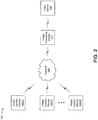
- FIG. 2 is a diagram of an example environment 200 in which systems and/or methods, described herein, may be implemented.
- environment 200 may include an image processing device 210, one or more image capture devices 220-1 through 220-N (N ⁇ 1) (hereinafter referred to collectively as “image capture devices 220," and individually as “image capture device 220"), a client device 230, and a network 240.
- Image capture devices 220 and individually as “image capture device 220"
- client device 230 a client device 230
- network 240 a network 240.
- Devices of environment 200 may interconnect via wired connections, wireless connections, or a combination of wired and wireless connections.
- Image processing device 210 may include a device capable of receiving, storing, generating, processing, and/or providing information.
- image processing device 210 may include a computing device (e.g., a desktop computer, a laptop computer, a tablet computer, a handheld computer, etc.), a server, a device in a cloud computing network, or a similar device.
- image processing device 210 may include a communication interface that allows image processing device 210 to receive information from and/or transmit information to image capture device 220, client device 230, or another device.
- Image capture device 220 may include a device capable of capturing an image (e.g., a photograph, a digital picture, a video, etc.).
- image capture device 220 may include a camera (e.g., a digital camera, a web camera, etc.), a video camera (e.g., a camcorder, a movie camera), a smart camera, a mobile telephone (e.g., a smartphone, a cellular telephone, etc.) a computing device (e.g., a desktop computer, a laptop computer, a tablet computer, a handheld computer, etc.), or a similar device.
- image capture device 220 may combine a set of captured images into a stitched image.
- image capture device 220 may receive information from and/or transmit information to image processing device 210 (e.g., captured images, a stitched image, information associated with captured images, etc.).
- Client device 230 may include one or more devices capable of receiving, generating, storing, processing, and/or providing information.
- client device 230 may include a communication and/or computing device, such as a mobile phone (e.g., a smart phone, etc.), a laptop computer, a tablet computer, a handheld computer, a wearable communication device (e.g., a smart wristwatch, a pair of smart eyeglasses, etc.), or a similar type of device.
- client device 230 may receive information from and/or transmit information to another device in environment 200.
- Network 240 may include one or more wired and/or wireless networks.
- network 240 may include a cellular network (e.g., a long-term evolution (LTE) network, a 3G network, a code division multiple access (CDMA) network, etc.), a public land mobile network (PLMN), a local area network (LAN), a wide area network (WAN), a metropolitan area network (MAN), a telephone network (e.g., the Public Switched Telephone Network (PSTN)), a private network, an ad hoc network, an intranet, the Internet, a fiber optic-based network, a cloud computing network, or the like, and/or a combination of these or other types of networks.
- LTE long-term evolution
- CDMA code division multiple access
- PLMN public land mobile network
- LAN local area network
- WAN wide area network
- MAN metropolitan area network
- PSTN Public Switched Telephone Network
- the number and arrangement of devices and networks shown in Fig. 2 are provided as an example. In practice, there may be additional devices and/or networks, fewer devices and/or networks, different devices and/or networks, or differently arranged devices and/or networks than those shown in Fig. 2 . Furthermore, two or more devices shown in Fig. 2 may be implemented within a single device, or a single device shown in Fig. 2 may be implemented as multiple, distributed devices. Additionally, or alternatively, a set of devices (e.g., one or more devices) of environment 200 may perform one or more functions described as being performed by another set of devices of environment 200.
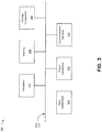
- Fig. 3 is a diagram of example components of a device 300.
- Device 300 may correspond to image processing device 210, image capture device 220, and/or client device 230.
- image processing device 210, image capture device 220, and/or client device 230 may include one or more devices 300 and/or one or more components of device 300.
- device 300 may include a bus 310, a processor 320, a memory 330, a storage component 340, an input component 350, an output component 360, and a communication interface 370.
- Bus 310 may include a component that permits communication among the components of device 300.
- Processor 320 is implemented in hardware, firmware, or a combination of hardware and software.
- Processor 320 may include a processor (e.g., a central processing unit (CPU), a graphics processing unit (GPU), an accelerated processing unit (APU), etc.), a microprocessor, and/or any processing component (e.g., a field-programmable gate array (FPGA), an application-specific integrated circuit (ASIC), etc.) that interprets and/or executes instructions.
- processor 320 may include one or more processors that can be programmed to perform a function.
- Memory 330 may include a random access memory (RAM), a read only memory (ROM), and/or another type of dynamic or static storage device (e.g., a flash memory, a magnetic memory, an optical memory, etc.) that stores information and/or instructions for use by processor 320.
- RAM random access memory
- ROM read only memory
- static storage device e.g., a flash memory, a magnetic memory, an optical memory, etc.
- Storage component 340 may store information and/or software related to the operation and use of device 300.
- storage component 340 may include a hard disk (e.g., a magnetic disk, an optical disk, a magneto-optic disk, a solid state disk, etc.), a compact disc (CD), a digital versatile disc (DVD), a floppy disk, a cartridge, a magnetic tape, and/or another type of computer-readable medium, along with a corresponding drive.
- Input component 350 may include a component that permits device 300 to receive information, such as via user input (e.g., a touch screen display, a keyboard, a keypad, a mouse, a button, a switch, a microphone, etc.). Additionally, or alternatively, input component 350 may include a sensor for sensing information (e.g., a global positioning system (GPS) component, an accelerometer, a gyroscope, an actuator, etc.). Output component 360 may include a component that provides output information from device 300 (e.g., a display, a speaker, one or more light-emitting diodes (LEDs), etc.).
- GPS global positioning system
- LEDs light-emitting diodes
- Communication interface 370 may include a transceiver-like component (e.g., a transceiver, a separate receiver and transmitter, etc.) that enables device 300 to communicate with other devices, such as via a wired connection, a wireless connection, or a combination of wired and wireless connections. Communication interface 370 may permit device 300 to receive information from another device and/or provide information to another device.
- communication interface 370 may include an Ethernet interface, an optical interface, a coaxial interface, an infrared interface, a radio frequency (RF) interface, a universal serial bus (USB) interface, a Wi-Fi interface, a cellular network interface, or the like.
- RF radio frequency
- USB universal serial bus
- Device 300 may perform one or more processes described herein. Device 300 may perform these processes in response to processor 320 executing software instructions stored by a computer-readable medium, such as memory 330 and/or storage component 340.
- a computer-readable medium is defined herein as a non-transitory memory device.
- a memory device includes memory space within a single physical storage device or memory space spread across multiple physical storage devices.
- Software instructions may be read into memory 330 and/or storage component 340 from another computer-readable medium or from another device via communication interface 370. When executed, software instructions stored in memory 330 and/or storage component 340 may cause processor 320 to perform one or more processes described herein. Additionally, or alternatively, hardwired circuitry may be used in place of or in combination with software instructions to perform one or more processes described herein. Thus, implementations described herein are not limited to any specific combination of hardware circuitry and software.
- device 300 may include additional components, fewer components, different components, or differently arranged components than those shown in Fig. 3 . Additionally, or alternatively, a set of components (e.g., one or more components) of device 300 may perform one or more functions described as being performed by another set of components of device 300.
- a set of components e.g., one or more components
- Fig. 4 is a flow chart of an example process 400 for determining whether to perform an object recognition operation on a stitched image.
- one or more process blocks of Fig. 4 may be performed by image processing device 210.
- one or more process blocks of Fig. 4 may be performed by another device or a group of devices separate from or including image processing device 210, such as image capture device 220 and client device 230.
- process 400 may include obtaining a set of images, including objects to be recognized, with one or more overlaps between images of the set of images (block 410).
- image processing device 210 may obtain a set of images that include one or more objects to be recognized.
- the set of images may be arranged in a grid, a row, or the like, with areas of overlap between adjacent images in the grid, row, or the like.
- Image processing device 210 may obtain the set of images from one or more image capture devices 220.
- a particular image capture device 220 may capture the set of images, and may provide the set of images to image processing device 210.
- a set of image capture devices 220 may each capture one or more images, of the set of images, and may collectively provide the set of images to image processing device 210.
- process 400 may include combining the set of images into a stitched image (block 420).
- image processing device 210 may combine the set of images into a stitched image.
- image processing device 210 may receive a stitched image from image capture device 220.
- image capture device 220 may capture the set of images, may combine the set of images into a single, stitched image, and may provide the stitched image to image processing device 210.
- image processing device 210 may receive additional information from image capture device 220 (e.g., an orientation of image capture device 220, a position of each image in the set of images, a relative position of each image in the set of images relative to each other image in the set of images, etc.), and may combine the set of images based on the additional information.
- additional information e.g., an orientation of image capture device 220, a position of each image in the set of images, a relative position of each image in the set of images relative to each other image in the set of images, etc.
- image processing device 210 may combine the set of images based on common features in overlapped areas. For example, image processing device 210 may detect common features in an overlapped area between a first image and a second image, and may combine the first image and the second image by aligning the common features. In some implementations, image processing device 210 may blend features of a first image and a second image. For example, image processing device 210 may determine luminosity values of an overlapped area in a first image and a second image, and may blend the luminosity values of the overlapped area to make the luminosity of the overlapped area uniform, as described in more detail in connection with Fig. 6 , below.
- image processing device 210 may project the set of images onto a particular plane based on homography matrices.
- a set of images may include images that are captured at different orientations, different locations, or the like.
- Image processing device 210 may determine homography matrices corresponding to one or more images, of the set of images, based on the orientations, based on common features of the images, or the like. Based on parameters of the homography matrices, image processing device 210 may project the set of images onto a particular plane.
- a homography matrix may include particular parameters.
- the homography matrix may include the following parameters, as shown in Table 1: Table 1.
- H 11 A scale factor in the x-direction with a constant scale factor in the y-direction H 12
- a shear factor in the x-direction proportionate to a distance from the origin in the y-direction H 13 A translation in the x-direction H 21
- a shear factor in the y-direction proportionate to a distance from the origin in the x-direction H 23
- H 31 A shear factor when a projected location of X is dependent on both X and Y H 32
- a shear factor when a projected location of Y is dependent on both X and Y H 33 1
- image processing device 210 may estimate the parameters based on the set of images. For example, image processing device 210 may detect common features in overlapped areas and may estimate the parameters based on the common features. As another example, image processing device 210 may obtain camera information identifying tilt, orientation, magnification, or the like, for image capture device 220, and may determine the homography matrices based on the camera information.
- process 400 may include determining one or more reliability scores for the set of images of the stitched image (block 430).
- image processing device 210 may determine reliability scores for the set of images.
- a reliability score for a particular image may indicate an expected quality of a stitched image that includes the particular image. For example, if an overlapped area of a first image differs in shared features, resolution, lighting, or the like, from a corresponding overlapped area of a second image, the reliability score for the first image may be relatively low (e.g., relative to if the overlapped area shared the features, resolution, lighting, or the like).
- the reliability score for the first image may be relatively high (e.g., relative to if the overlapped area does not share the threshold quantity of features).
- process 400 may include determining that an object recognition operation is likely to be successful based on a predictive model and based on the reliability scores (block 440). For example, image processing device 210 may determine that an object recognition operation for the stitched image is likely to be successful for the stitched image. Image processing device 210 may determine that an object recognition operation is successful when a threshold ratio of identified objects to unidentified objects is satisfied, when a threshold quantity of objects is recognized, or the like.
- Image processing device 210 may determine whether the object recognition operation is likely to be successful based on a predictive model. For example, image processing device 210 may obtain (e.g., receive, train, etc.) a predictive model that predicts outcomes of object recognition operations based on reliability scores.
- a predictive model that predicts outcomes of object recognition operations based on reliability scores.
- Image processing device 210 may input, to the predictive model, a set of reliability scores (e.g., a mean of the set, a median of the set, a mode of the set, a weighted average of the set, a subset of the set, a range of the set, a first quartile value of the set, a second quartile value of the set, a third quartile value of the set, a standard deviation of the set, a variance of the set, etc.) for the images included in the stitched image, and may output a predicted outcome of an object recognition operation.
- the predictive model may output a predicted ratio of identified objects to unidentified objects, a predicted quantity of objects identified, a binary result (e.g., pass/fail, perform/do not perform, good/bad, etc.), or the like.
- image processing device 210 may train the predictive model. For example, image processing device 210 may obtain training data (e.g., known reliability scores and known results of object recognition operations corresponding to the known reliability scores). Image processing device 210 may analyze the training data to determine a set of rules for predicting a result of an object recognition operation based on one or more reliability scores.
- training data e.g., known reliability scores and known results of object recognition operations corresponding to the known reliability scores.
- Image processing device 210 may analyze the training data to determine a set of rules for predicting a result of an object recognition operation based on one or more reliability scores.
- process 400 may include performing the object recognition operation on the stitched image (block 450).
- image processing device 210 may perform the object recognition operation on the stitched image based on determining that the object recognition operation is likely to be successful (e.g., based on the output of the predictive model, etc.).
- image processing device 210 may cause another device to perform the object recognition operation.
- another device e.g., image capture device 220, client device 230, a device not shown in Fig. 2 , etc.
- image processing device 210 may provide information to another device.
- image processing device 210 may provide the stitched image and/or a result of the object recognition operation to client device 210, or another device.
- image processing device 210 may selectively perform the object recognition operation based on whether the result of the object recognition operation is likely to satisfy a threshold. For example, image processing device 210 may use the predictive model to determine a likelihood that a result of the object recognition operation is likely to satisfy a threshold based on reliability scores of the set of images. When the result of the object recognition operation is likely to satisfy a threshold quantity of object identified, a threshold ratio of objects identified, or the like, image processing device 210 may perform the object recognition operation. When the result of the object recognition operation is not likely to satisfy the threshold, image processing device 210 may not perform the object recognition operation. In such cases, image processing device 210 may provide information to another device.
- image processing device 210 may notify image capture device 220 and/or client device 230 that the object recognition operation is not likely to be successful, may cause image capture device 220 to capture additional images of one or more of the objects included in the stitched image, or the like.
- process 400 may include updating the predictive model to predict whether the object recognition operation is likely to be successful based on a result of performing the object recognition operation (block 460).
- image processing device 210 may update the predictive model based on a result of performing the object recognition operation.
- image processing device 210 may compare the output of the predictive model to the result of performing the object recognition operation, and may modify parameters or rules of the predictive model based on a difference between the output and the result. In this way, image processing device 210 updates a predictive model to predict the result of performing the object recognition operation, which conserves processor and memory resources by reducing a quantity of unnecessary object recognition operations performed.
- process 400 may include additional blocks, fewer blocks, different blocks, or differently arranged blocks than those depicted in Fig. 4 . Additionally, or alternatively, two or more of the blocks of process 400 may be performed in parallel.
- Figs. 5A and 5B are diagrams of an example implementation 500 relating to example process 400 shown in Fig. 4 .
- Figs. 5A and 5B show an example of determining whether to perform object recognition on a stitched image.
- image processing device 210 may receive four images from image capture devices 220-1 through 220-4. As further shown, the four images overlap in some overlapped areas. Here, image 1, image 2, and image 3 show object A, image 2 and image 4 show object B, image 3 and image 4 show object C, and image 3 and image 4 show object D. As shown by reference number 504, image processing device 210 may calculate homography matrices for the four images. In some implementations, image processing device 210 may determine the homography matrices based on shared objects A, B, C, and D. Additionally, or alternatively, image processing device 210 may determine the homography information based on camera information from image capture devices 220-1 through 220-4.
- image capture device 220 may stitch the four images into a stitched image based on the homography matrices of the four images and based on objects A, B, C, and D in the overlapped areas.
- image processing device 210 may project the four images onto a common plane, and may align the four images based on the objects in the overlapped area, as shown by reference number 508.
- image processing device 210 may determine reliability scores corresponding to each image, of the four images. For example, in one possible implementation, image processing device 210 may combine each image with each neighboring image (i.e., image 1/image 2, image 1/image 3, image 1/image 4, image 2/image 3, image 2/image 4, and image 3/image 4), and may determine reliability scores for each pair of images.
- image processing device 210 may combine each image with each neighboring image (i.e., image 1/image 2, image 1/image 3, image 1/image 4, image 2/image 3, image 2/image 4, and image 3/image 4), and may determine reliability scores for each pair of images.
- image processing device 210 may combine each image/neighbor pair into composite images based on hue, saturation, and/or value parameters of the pair of images. As shown, image processing device 210 may erode the composite image to eliminate shared details and may dilate the eroded composite image to magnify differences between the pair of images, which may be shown in the eroded composite image. As further shown, image processing device 210 may take mean hue-saturation-value measurements of the eroded and dilated composite images to determine a reliability score for images 1-4.
- image processing device 210 may take a mean hue parameter value of a set of points in a particular composite image, a mean saturation parameter value of the set of points in the particular composite image, and a mean value parameter value of the set of points in the particular composite image.
- the reliability score for the particular composite image in some implementations, may be determined based on a mean of the mean hue, mean saturation, and mean value parameter values for the particular composite image. A more detailed description of determining reliability scores is provided, with reference to Fig. 6 , below.
- image processing device 210 may generate a composite image based on a proper subset of a set of images (e.g., based on images 1 and 2, based on images 1, 2, and 3, based on images 1, 2, and 4, based on images 1, 3, and 4, based on images 2, 3, and 4, etc.). In some implementations, image processing device 210 may generate a composite image based on a set of images.
- image processing device 210 may determine reliability scores of 0.93, 0.95, 0.92, and 0.91 for the four images.
- reliability scores range between values of 0 and 1, and a reliability score that is closer to 1 indicates that an image is likely to produce a more reliable stitched image than an image with a reliability score that is closer to 0.
- image processing device 210 determines a mean value of the reliability scores (e.g., 0.92), and a standard deviation of the reliability scores (e.g., 0.017).
- image processing device 210 may determine whether an object recognition operation is likely to be successful based on a relationship between reliability scores and object recognition success rates. As shown by reference number 516, the relationship between the reliability scores and the object recognition success rates may be determined based on a predictive model. The predictive model may be trained based on past object recognition success rates as compared with reliability scores corresponding to the past object recognition success rates.
- image processing device 210 may determine whether the object recognition operation is likely to be successful based on the mean of the four reliability scores, plus or minus one standard deviation.
- image processing device 210 determines to perform the object recognition operation (e.g., as shown by PASS) when the mean plus or minus one standard deviation is between 1 and 0.9, and when the mean plus or minus one standard deviation is between 0.95 and 0.85.
- image processing device 210 determines not to perform the object recognition operation (e.g., as shown by BLOCK) when the mean plus or minus one standard deviation is between 0.95 and 0.7, and when the mean plus or minus one standard deviation is below 0.7.
- image processing device 210 determines that the object recognition operation is likely to be successful (e.g., based on the mean of the four reliability scores being equal to 0.92, and the standard deviation being equal to 0.017). As further shown, image processing device 210 performs the object recognition operation on the stitched image. Here, image processing device 210 correctly identifies object A, object B, and object C. As shown, image processing device 210 incorrectly identifies object D as a different object (object M). As shown by reference number 520, image processing device 210 determines an object recognition success rate of 75%. As shown by reference number 522, image processing device 210 updates the predictive model based on the reliability scores and the object recognition success rate. In this way, image processing device 210 determines whether to proceed with the objection recognition operation based on the reliability scores of the set of images, which conserves processor power that may be used for unsuccessful object recognition operations and improves accuracy of object recognition operations.
- FIGS. 5A and 5B are provided merely as an example. Other examples are possible and may differ from what was described with regard to Figs. 5A and 5B .
- Fig. 6 is a flow chart of an example process 600 for determining a reliability score.
- one or more process blocks of Fig. 6 may be performed by image processing device 210.
- one or more process blocks of Fig. 6 may be performed by another device or a group of devices separate from or including image processing device 210, such as image capture device 220 and client device 230.
- process 600 may include obtaining two images that share an overlapped area (block 610).
- image processing device 210 may obtain two or more images from image capture device 220. Two images, of the two or more images, may share an overlapped area. For example, a portion of a first image may depict the same object as a corresponding portion of a second image.
- image processing device 210 may determine that the images share the overlapped area. For example, image processing device 210 may detect shared features in the overlapped area, may determine that the two images are adjacent in a grid of images, or the like.
- image processing device 210 may receive a stitched image, and may determine reliability scores for two or more images that are included in the stitched image. In such a case, image processing device 210 may obtain the stitched image from image capture device 220, client device 230, or the like.
- process 600 may include determining a mean luminosity of the overlapped area (block 620).
- image processing device 210 may determine a mean luminosity of the overlapped area in each of the two images.
- Image processing device 210 may determine the mean luminosity by determining a mean luminosity value of each pixel in the overlapped area, by determining a mean luminosity value of portions of the overlapped area, or the like.
- Image processing device 210 may determine the mean luminosity value to improve a quality of the composite image.
- image processing device 210 may modify the luminosity of the two images, in the overlapped area, to match the luminosities, as described in more detail below.
- process 600 may include normalizing the luminosity of the overlapped region (block 630).
- image processing device 210 may normalize the luminosity of the overlapped area of the two images.
- image processing device 210 may determine a normalized luminosity by taking a mean value of the mean luminosities of the two images.
- image processing device 210 may apply a function to determine the normalized luminosity.
- image processing device 210 may blend the normalized luminosity of the overlapped area from a mean luminosity value of a first image to a mean luminosity value of a second image. In this way, image processing device 210 prevents inconsistencies in luminosity from appearing in between images in the composite image.
- process 600 may include converting the two images to a hue-saturation-value (HSV) color space (block 640).
- HSV hue-saturation-value
- the two images may be in a red-green-blue (RGB) color space.
- Image processing device 210 may convert the two images to a cylindrical-coordinate color model, such as an HSV color space. By converting the two images to the HSV color space, image processing device 210 may improve efficiency of processing the two images and thus conserve processor resources.
- image processing device 210 may convert the two images to another color space, such as a hue-saturation-intensity color space, a hue-saturation-lightness color space, or the like.
- another device such as image capture device 220, may convert the two images to the HSV color space, and may provide the converted images to image processing device 210.
- color parameters e.g., hue parameters, saturation parameters, value parameters, lightness parameters, intensity parameters, etc.
- process 600 may include filtering the two images to reduce noise (block 650).
- image processing device 210 may filter the two images to reduce noise in the two images. By reducing noise in the two images, image processing device 210 improves accuracy of the composite image and increases reliability of object detection, thus saving an organization that implements the object detection time and money.
- image processing device 210 may perform a smoothing filtering operation, such as a box filtering operation, a Gaussian filtering operation, or the like. By performing a box filtering operation, image processing device 210 conserves processing resources as compared to a Gaussian filtering operation.
- image processing device 210 By performing a Gaussian filtering operation, image processing device 210 reduces high-frequency artifacts that may be present in an image that is processed based on a box filtering operation, which improves accuracy of the composite image and thus conserves resources of the organization that implements the object detection.
- process 600 may include obtaining a composite image based on hue, saturation, and/or value parameters of the two images (block 660).
- image processing device 210 may obtain a composite image based on hue, saturation, and/or value parameters of the two images.
- image processing device 210 may obtain the composite image by combining the two images based on a hue, saturation, and/or value parameter of the two images.
- image processing device 210 may set a hue parameter of the composite image based on a combination of hue parameters of the two images, a saturation parameter of the composite image based on a combination of saturation parameters of the two images, and a value parameter of the composite image based on a combination of value parameters of the two images.
- image processing device 210 may add the parameters, subtract the parameters, multiply the parameters, divide the parameters, average the parameters, or may perform another operation on the parameters.
- image processing device 210 may set hue, saturation, and value parameters in the composite image based on a value of a particular parameter. As an example, assume that a particular pixel in a first image is associated with a value parameter of 0.28, and assume that a corresponding pixel in a second image is associated with a value parameter of 0.82. Image processing device 210 may subtract the value parameters of the particular pixels to obtain a value difference of 0.54. In some implementations, image processing device 210 may set hue, saturation, and value parameters of the resulting composite image to the value difference. For example, in the particular pixel of the composite image, (Hue, Saturation, Value) may equal [0.54 0.54 0.54].
- image processing device 210 generates a composite image that identifies differences in value between the two images using a lightness of a pixel in the composite image, which aids in identifying images that may generate a poorly stitched image when combined.
- process 600 may include performing one or more morphological operations on the composite image (block 670).
- image processing device 210 may perform one or more morphological operations on the composite image.
- Image processing device 210 may perform morphological operations to remove overlapped details and/or to strengthen non-overlapped details. For example, when the composite image includes a lighter area corresponding to a greater difference between the two images, image processing device 210 may perform a morphological operation to increase a size and/or brightness of the lighter area. Additionally, or alternatively, when the composite image includes a dark area corresponding to a lesser difference between the two images, image processing device 210 may perform a morphological operation to decrease a size and/or brightness of the darker area.
- the morphological operation may include erosion.
- image processing device 210 may erode the composite image one or more times to eliminate small details, corresponding to lesser differences between the two images.
- the morphological operation may include dilation.
- image processing device 210 may dilate the composite image one or more times to magnify non-overlapped details (e.g., lighter areas corresponding to greater differences between the two images).
- image processing device 210 may erode the composite image before dilating the composite image, which may eliminate lesser differences before magnifying the remaining, greater differences.
- image processing device 210 may perform another type of morphological operation (e.g., a dilation followed by an erosion, a hit and miss transform, etc.).
- process 600 may include determining mean hue, saturation, and/or value parameters of the composite image (block 680).
- image processing device 210 may determine mean hue, saturation, and/or value parameters of the composite image.
- image processing device 210 may determine a mean hue parameter, a mean saturation parameter, and/or a mean value parameter for the composite image.
- image processing device 210 may determine a mean of a mean hue parameter, a mean saturation parameter, and/or a mean value parameter for the composite image.
- process 600 may include determining a reliability score based on the mean hue, saturation, and/or value parameters (block 690).
- image processing device 210 may determine a reliability score based on the mean hue, saturation, and/or value parameters.
- image processing device 210 may determine a mean of the hue, saturation, and value parameters for the composite image, and may subtract the mean from 1. For example, a reliability score of 1 may be a highest attainable reliability score, corresponding to no difference between the two images. Image processing device 210 may determine the mean hue, saturation, and/or value parameters for the composite image, corresponding to differences between the two images, and may subtract the mean hue, saturation, and/or value parameters from 1 to determine the reliability score.
- image processing device 210 may determine reliability scores for multiple images.
- a stitched image may include multiple images (e.g., four images, eight images, etc.).
- Image processing device 210 may determine reliability scores for each of the images that are included in the stitched image.
- image processing device 210 may determine reliability scores for each of the overlapped areas of the particular image, and may combine the reliability scores for the overlapped areas of the particular image.
- a reliability score may be an average of the reliability scores, may be a sum of the reliability scores, may be a weighted sum of the reliability scores, or the like, to determine a final reliability score for the particular image.
- Image processing device 210 may determine whether an object recognition operation is likely to be successful for the stitched image based on the reliability scores for the images in the stitched image, as described in more detail in connection with Fig. 4 , above. In this way, image processing device 210 determines reliability scores for the images included in a stitched image, based on which image processing device 210 determines whether the object recognition operation is likely to be successful. Thus, image processing device 210 conserves processor resources of image processing device 210 and/or client device 230 and organizational resources (e.g., time, money, worker hours, etc.) for an organization that implements the object recognition operation.
- organizational resources e.g., time, money, worker hours, etc.
- process 600 may include additional blocks, fewer blocks, different blocks, or differently arranged blocks than those depicted in Fig. 6 . Additionally, or alternatively, two or more of the blocks of process 600 may be performed in parallel.
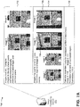
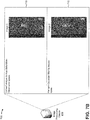
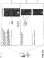
- Figs. 7A-7D are diagrams of an example implementation 700 relating to example process 600 shown in Fig. 6 .
- Figs. 7A-7D show an example of determining a reliability score.
- image processing device 210 may receive two images (e.g., image 1 and image 2). Assume that image processing device 210 receives the two images from image capture device 220. As further shown, image processing device 210 may compare image 1 and image 2 to identify shared points in the two images and to determine homography matrices to project image 1 and image 2 onto a common plane. Assume that image processing device 210 projects the images onto the common plane based on two homography matrices corresponding to image 1 and image 2, respectively.
- image processing device 210 may determine parts of the images to overlay, which are indicated by areas inside the dotted lines. Here, a majority of images 1 and 2 are overlaid. Images 1 and 2, as projected to the common plane, are shown by reference number 706. As shown by reference number 708, image processing device 210 may determine a mean luminosity for the overlapped part of each image. Here, image processing device 210 determines a mean luminosity of 110 (e.g., out of 255) for image 1, and a mean luminosity of 111 for image 2. As further shown, image processing device 210 normalizes luminosity of the overlapped area. Here, image processing device 210 normalizes the luminosity based on an average value for the two images (e.g., 110.5).
- image processing device 210 may convert the images to a hue-saturation-value (HSV) color space.
- HSV hue-saturation-value
- image 2 is shown in the HSV color space.
- image processing device 210 converts image 1 to the HSV color space (not shown).
- image processing device 210 may perform a Gaussian filter to reduce noise in images 1 and 2.
- image 2 is shown after applying the Gaussian filter.
- image processing device 210 applies the Gaussian filter to image 1 (not shown).
- image processing device 210 may combine images 1 and 2 to generate a composite image. As shown, image processing device 210 may combine images 1 and 2 by determining a difference in a value parameter at corresponding points (e.g., pixels) in image 1 and image 2. As further shown, to generate the composite image, image processing device 210 may set a hue parameter, a saturation parameter, and a value parameter of each point in the composite image to be equal to a difference in value at the particular point of image 1 and image 2.
- image processing device 210 may erode the composite image to eliminate details from the composite image that are shared by image 1 and image 2. As shown by reference number 718, image processing device 210 may dilate the composite image after eroding the composite image to exaggerate the remaining, non-shared details (e.g., the white area at the bottom of the image, the white area near the center of the image, the white area near the top of the image, etc.).
- image processing device 210 may erode the composite image to eliminate details from the composite image that are shared by image 1 and image 2.
- image processing device 210 may dilate the composite image after eroding the composite image to exaggerate the remaining, non-shared details (e.g., the white area at the bottom of the image, the white area near the center of the image, the white area near the top of the image, etc.).
- image processing device 210 may compute mean hue (H), saturation (S), and value (V) parameters for the composite image. As further shown, assume that the mean hue (Mean H), mean saturation (Mean S), and mean value (Mean V) parameters are each equal to 0.07 for the composite image. As further shown, image processing device 210 may determine a reliability score for the image by determining a mean of the mean hue, mean saturation, and mean value parameters, and by subtracting the determined mean from 1. As shown, image processing device 210 determines that the composite image is associated with a reliability score of 0.94. Based on the composite image being associated with a reliability score of 0.94, image processing device 210 determines that image 1 and image 2 are associated with a reliability score of 0.94.
- image processing device 210 determines a reliability score based on differences between image 1 and image 2, which permits image processing device 210 to predict whether an object recognition operation will be successful for a stitched image that includes image 1 and image 2.
- image processing device 210 conserves processor and memory resources that might otherwise be consumed for object recognition operations that are unlikely to succeed and conserves resources (e.g., time, money, worker hours, etc.) for an organization that implements the object recognition operation.
- FIGS. 7A-7D are provided merely as an example. Other examples are possible and may differ from what was described with regard to Figs. 7A-7D .
- Implementations described herein enable an image processing device to predict a result of the object recognition operation based on reliability scores for the set of images. Based on the reliability scores, the image processing device or another device (e.g., a client device, based on a user input) may determine whether to proceed with the object recognition operation. In this way, the image processing device conserves processor and memory resources and improves accuracy of object recognition, which saves time and money for the organization implementing the object recognition operation.
- the term component is intended to be broadly construed as hardware, firmware, and/or a combination of hardware and software.
- satisfying a threshold may refer to a value being greater than the threshold, more than the threshold, higher than the threshold, greater than or equal to the threshold, less than the threshold, fewer than the threshold, lower than the threshold, less than or equal to the threshold, equal to the threshold, etc.
Landscapes
- Engineering & Computer Science (AREA)
- Theoretical Computer Science (AREA)
- Physics & Mathematics (AREA)
- General Physics & Mathematics (AREA)
- Multimedia (AREA)
- Computer Vision & Pattern Recognition (AREA)
- Evolutionary Computation (AREA)
- Artificial Intelligence (AREA)
- General Health & Medical Sciences (AREA)
- Medical Informatics (AREA)
- Software Systems (AREA)
- Health & Medical Sciences (AREA)
- Databases & Information Systems (AREA)
- Computing Systems (AREA)
- Quality & Reliability (AREA)
- Data Mining & Analysis (AREA)
- Life Sciences & Earth Sciences (AREA)
- Bioinformatics & Cheminformatics (AREA)
- Bioinformatics & Computational Biology (AREA)
- Evolutionary Biology (AREA)
- General Engineering & Computer Science (AREA)
- Probability & Statistics with Applications (AREA)
- Image Analysis (AREA)
- User Interface Of Digital Computer (AREA)
Claims (9)
- Eine Vorrichtung, die Folgendes umfasst:
einen oder mehrere Prozessoren, um Folgendes zu bewerkstelligen:Empfangen einer Vielzahl von Bildern für einen Objekterkennungsvorgang,wobei die Vielzahl von Bildern in einem Raster angeordnet ist, mit Bereichen der Überlappung zwischen benachbarten Bildern im Raster;wobei der Objekterkennungsvorgang ein oder mehrere Objekte in der Vielzahl von Bildern identifiziert, nachdem die Vielzahl von Bildern zu einem zusammengesetzten Bild kombiniert wurde;Kombinieren der Vielzahl von Bildern im zusammengesetzten Bild;Bestimmen eines überlappenden Bereichs eines ersten Bildes und eines zweiten Bildes aus der Vielzahl von Bildern;Bestimmen einer mittleren Helligkeit (luminosity) des überlappenden Bereichs;Normalisieren einer Helligkeit des überlappenden Bereichs des ersten Bildes und des zweiten Bildes basierend auf der mittleren Helligkeit;Umwandeln des ersten Bildes und des zweiten Bildes in einen HSV-Farbraum;Erhalten eines zusammengesetzten Bildes basierend auf Farbwert-, Farbsättigungs- und/oder Hellwertparametern des ersten Bildes und des zweiten Bildes;wobei das zusammengesetzte Bild erzeugt wird basierend auf Unterschieden an entsprechenden Stellen im ersten Bild und im zweiten Bild,wobei die Unterschiede zwischen den entsprechenden Punkten im ersten Bild und im zweiten Bild Unterschiede bezüglich mindestens einem aus einem Farbwertparameter, einem Farbsättigungsparameter oder einem Hellwertparameter beinhalten;Bestimmen eines Verlässlichkeitswerts für das erste Bild und das zweite Bild basierend auf mindestens einem aus einem Mittel der Farbwertparameter einer Vielzahl von Punkten im zusammengesetzten Bild, einem Mittel der Farbsättigungsparameter einer Vielzahl von Punkten im zusammengesetzten Bild oder einem Mittel der Hellwertparameter einer Vielzahl von Punkten im zusammengesetzten Bild;
wobei der Verlässlichkeitswert eine Qualität des zusammengefügten Bildes voraussagt, das das erste Bild und das zweite Bild aus der Vielzahl von Bildern beinhaltet;Bestimmen, ob es wahrscheinlich ist, dass ein Ergebnis des Objekterkennungsvorgangs einen Schwellenwert erfüllt, der auf einem prädiktiven Modell basiert, wobei das prädiktive Modell eine Wahrscheinlichkeit ausgibt, dass das Ergebnis des Objekterkennungsvorgangs den Schwellenwert erfüllt, der auf dem Zuverlässigkeitswert basiert; undselektives Ausführen des Objekterkennungsvorgangs basierend darauf, ob es wahrscheinlich ist, dass das Ergebnis des Objekterkennungsvorgangs den Schwellenwert erfüllt. - Die Vorrichtung nach Anspruch 1, wobei der eine oder die mehreren Prozessoren ferner dienen, um Folgendes zu bewerkstelligen:
Aktualisieren des prädiktiven Modells basierend auf Ergebnissen der Durchführung des Objekterkennungsvorgangs und basierend auf dem Verlässlichkeitswert. - Die Vorrichtung nach Anspruch 1, wobei der eine oder die mehreren Prozessoren bei der Bestimmung des Zuverlässigkeitswertes dazu dienen, Folgendes zu bewerkstelligen:Durchführen mindestens einer morphologischen Operation am zusammengesetzten Bild,wobei die morphologische Operation mindestens eine der Folgenden beinhaltet: eine erste Operation zum Erodieren des zusammengesetzten Bildes oder eine zweite Operation zum Erweitern des zusammengesetzten Bildes.
- Die Vorrichtung nach Anspruch 1, wobei der eine oder die mehreren Prozessoren bei der Bestimmung des Zuverlässigkeitswertes dazu dienen, Folgendes zu bewerkstelligen:
Durchführen eines Filtervorgangs für das erste Bild und das zweite Bild, um das Rauschen im ersten Bild und im zweiten Bild zu reduzieren,
wobei der Filtervorgang einen oder mehrere der folgenden Punkte beinhaltet:einen Box-Filtervorgang odereine Gaußsche Filterung. - Ein computerimplementiertes Verfahren, das Folgendes umfasst:Empfangen, durch eine Vorrichtung, eines zusammengesetzten Bildes für einen Objekterkennungsvorgang,wobei das zusammengesetzte Bild eine Vielzahl von Bildern beinhaltet, undwobei der Objekterkennungsvorgang ein oder mehrere Objekte im zusammengesetzten Bild identifiziert;Erhalten, durch die Vorrichtung, der Vielzahl von Bildern, wobei die Vielzahl von Bildern in einem Raster angeordnet ist, mit Bereichen der Überlappung zwischen benachbarten Bildern im Raster;Bestimmen eines überlappenden Bereichs von einem ersten Bild und einem zweiten Bild aus der Vielzahl von Bildern;Bestimmen einer mittleren Helligkeit des überlappenden Bereichs;Normalisieren einer Helligkeit des überlappenden Bereichs des ersten Bildes und des zweiten Bildes basierend auf der mittleren Helligkeit;Umwandeln des ersten Bildes und des zweiten Bildes in einen HSV-Farbraum;Erhalten eines zusammengesetzten Bildes basierend auf Farbwert-, Farbsättigungs- und/oder Hellwertparametern des ersten Bildes und des zweiten Bildes;wobei das zusammengesetzte Bild erzeugt wird basierend auf Unterschieden an entsprechenden Stellen im ersten Bild und im zweiten Bild,wobei die Unterschiede zwischen den entsprechenden Punkten im ersten Bild und im zweiten Bild Unterschiede bezüglich mindestens einem aus einem Farbwertparameter, einem Farbsättigungsparameter oder einem Hellwertparameter beinhalten;Bestimmen eines Verlässlichkeitswerts für das erste Bild und das zweite Bild basierend auf mindestens einem aus einem Mittel der Farbwertparameter einer Vielzahl von Punkten im zusammengesetzten Bild, einem Mittel der Farbsättigungsparameter einer Vielzahl von Punkten im zusammengesetzten Bild oder einem Mittel der Hellwertparameter einer Vielzahl von Punkten im zusammengesetzten Bild;wobei der Verlässlichkeitswert einer Qualität des zusammengefügten Bildes entspricht, das das erste Bild und das zweite Bild aus der Vielzahl von Bildern beinhaltet;Bestimmen, durch die Vorrichtung, ob es wahrscheinlich ist, dass ein Ergebnis des Objekterkennungsvorgangs einen Schwellenwert erfüllt, der auf einem prädiktiven Modell basiert, wobei das prädiktive Modell eine Wahrscheinlichkeit ausgibt, dass das Ergebnis des Objekterkennungsvorgangs den Schwellenwert erfüllt, der auf dem Zuverlässigkeitswert basiert; undDurchführen, durch die Vorrichtung, des Objekterkennungsvorgangs basierend auf dem Ergebnis, dass der Objekterkennungsvorgang wahrscheinlich den Schwellenwert erfüllt.
- Das Verfahren nach Anspruch 5, wobei das Bestimmen des Zuverlässigkeitswertes Folgendes umfasst:Bestimmen von mindestens zwei Zuverlässigkeitswerten für ein bestimmtes Bild aus der Vielzahl von Bildern,wobei das bestimmte Bild mindestens zwei weitere Bilder aus der Vielzahl der Bilder in dem zusammengesetzten Bild überlappt; undKombinieren der mindestens zwei Zuverlässigkeitswerte für das bestimmte Bild, um einen endgültigen Zuverlässigkeitswert für das bestimmte Bild zu bestimmen.
- Das Verfahren nach Anspruch 6, das ferner Folgendes umfasst:Identifizieren des einen oder der mehreren Objekte basierend auf dem Objekterkennungsvorgang; undBereitstellen von Informationen, die das eine oder die mehreren Objekte identifizieren.
- Ein Computerprogrammprodukt, das maschinenausführbare Anweisungen umfasst, die, wenn sie von einem Prozessor geladen und ausgeführt werden, bewirken, dass der Prozessor Operationen gemäß dem Verfahren nach irgendeinem der Ansprüche von 5 bis 7 ausführt.
- Ein Computersystem zum Vorhersagen der Genauigkeit der Objekterkennung in einem zusammengesetzten Bild, wobei das System konfiguriert ist, um Operationen nach irgendeinem der Ansprüche von 5 bis 7 durchzuführen.
Applications Claiming Priority (2)
| Application Number | Priority Date | Filing Date | Title |
|---|---|---|---|
| IN4784CH2015 | 2015-09-09 | ||
| US14/921,372 US9767387B2 (en) | 2015-09-09 | 2015-10-23 | Predicting accuracy of object recognition in a stitched image |
Publications (2)
| Publication Number | Publication Date |
|---|---|
| EP3142045A1 EP3142045A1 (de) | 2017-03-15 |
| EP3142045B1 true EP3142045B1 (de) | 2020-01-22 |
Family
ID=58190147
Family Applications (1)
| Application Number | Title | Priority Date | Filing Date |
|---|---|---|---|
| EP15199566.9A Active EP3142045B1 (de) | 2015-09-09 | 2015-12-11 | Vorhersage der genauigkeit von objekterkennung in einem zusammengesetzten bild |
Country Status (3)
| Country | Link |
|---|---|
| US (1) | US9767387B2 (de) |
| EP (1) | EP3142045B1 (de) |
| AU (1) | AU2016225841B2 (de) |
Families Citing this family (12)
| Publication number | Priority date | Publication date | Assignee | Title |
|---|---|---|---|---|
| US9721371B2 (en) * | 2015-12-02 | 2017-08-01 | Caterpillar Inc. | Systems and methods for stitching metallographic and stereoscopic images |
| SE1630035A1 (en) * | 2016-02-26 | 2017-08-27 | Katam Tech Ab | Methods, devices and computer programs for positioning |
| JP2018026706A (ja) * | 2016-08-10 | 2018-02-15 | パナソニックIpマネジメント株式会社 | 画像処理装置、画像表示装置、画像処理システム、及び画像処理方法 |
| JP6960997B2 (ja) * | 2017-08-09 | 2021-11-05 | 富士フイルム株式会社 | 画像処理システム、サーバ装置、画像処理方法、及び画像処理プログラム |
| US11495041B2 (en) * | 2019-03-29 | 2022-11-08 | Jumio Corporation | Biometric identification using composite hand images |
| CN110276744B (zh) * | 2019-05-15 | 2021-10-26 | 北京航空航天大学 | 图像拼接质量的测评方法及装置 |
| US11210562B2 (en) * | 2019-11-19 | 2021-12-28 | Salesforce.Com, Inc. | Machine learning based models for object recognition |
| CN111047510B (zh) | 2019-12-17 | 2023-02-14 | 大连理工大学 | 一种基于标定的大视场角图像实时拼接方法 |
| CN111898699B (zh) * | 2020-08-11 | 2024-05-10 | 海之韵(苏州)科技有限公司 | 一种船体目标自动检测识别方法 |
| EP4036851B1 (de) * | 2021-02-01 | 2024-07-31 | Axis AB | Verfahren und bildverarbeitungsvorrichtung zur auswertung einer ausrichtung von zusammengesetzten bildern |
| CN115393935B (zh) * | 2022-08-24 | 2026-01-09 | 深圳万兴软件有限公司 | 人脸特征点的滤波处理方法、装置、设备及存储介质 |
| US20250193339A1 (en) * | 2023-12-11 | 2025-06-12 | Advanced Micro Devices, Inc. | Videoconference image enhancement based on scene models |
Family Cites Families (8)
| Publication number | Priority date | Publication date | Assignee | Title |
|---|---|---|---|---|
| CA2603522A1 (en) | 2005-04-13 | 2006-10-26 | Store Eyes, Inc. | System and method for measuring display compliance |
| GB0514715D0 (en) * | 2005-07-18 | 2005-08-24 | Isis Innovation | Combination of images |
| US20090192921A1 (en) * | 2008-01-24 | 2009-07-30 | Michael Alan Hicks | Methods and apparatus to survey a retail environment |
| US8396269B2 (en) | 2010-04-08 | 2013-03-12 | Digital Pathco LLC | Image quality assessment including comparison of overlapped margins |
| KR20140060760A (ko) * | 2012-11-12 | 2014-05-21 | 엘지전자 주식회사 | 어레이 카메라, 휴대 단말기 및 그 동작 방법 |
| US9064304B2 (en) | 2013-03-18 | 2015-06-23 | General Electric Company | Image quality assessment of microscopy images |
| US9495606B2 (en) | 2014-02-28 | 2016-11-15 | Ricoh Co., Ltd. | Method for product recognition from multiple images |
| CA2966635C (en) * | 2014-11-21 | 2023-06-20 | Christopher M. Mutti | Imaging system for object recognition and assessment |
-
2015
- 2015-10-23 US US14/921,372 patent/US9767387B2/en active Active
- 2015-12-11 EP EP15199566.9A patent/EP3142045B1/de active Active
-
2016
- 2016-09-07 AU AU2016225841A patent/AU2016225841B2/en active Active
Non-Patent Citations (1)
| Title |
|---|
| None * |
Also Published As
| Publication number | Publication date |
|---|---|
| US9767387B2 (en) | 2017-09-19 |
| AU2016225841A1 (en) | 2017-03-23 |
| US20170068840A1 (en) | 2017-03-09 |
| AU2016225841B2 (en) | 2017-08-03 |
| EP3142045A1 (de) | 2017-03-15 |
Similar Documents
| Publication | Publication Date | Title |
|---|---|---|
| EP3142045B1 (de) | Vorhersage der genauigkeit von objekterkennung in einem zusammengesetzten bild | |
| CN101828201B (zh) | 图像处理装置及方法、学习装置及方法 | |
| US9524558B2 (en) | Method, system and software module for foreground extraction | |
| US11354889B2 (en) | Image analysis and processing pipeline with real-time feedback and autocapture capabilities, and visualization and configuration system | |
| US9047673B2 (en) | Apparatus and method for extracting target, and recording medium storing program for performing the method | |
| CN111340749B (zh) | 图像质量的检测方法、装置、设备及存储介质 | |
| US20210271913A1 (en) | Information processing apparatus, information processing method, and storage medium | |
| US20230334235A1 (en) | Detecting occlusion of digital ink | |
| JP6458570B2 (ja) | 画像処理装置および画像処理方法 | |
| US20210082127A1 (en) | Image analysis apparatus, image analysis method, and storage medium to display information representing flow quantity | |
| JP6520919B2 (ja) | 画像補正装置、画像補正方法およびプログラム | |
| EP2709063A1 (de) | Bildverarbeitungsvorrichtung, computerlesbares Aufzeichnungsmedium und Bildverarbeitungsverfahren | |
| US10140555B2 (en) | Processing system, processing method, and recording medium | |
| JP2004030007A (ja) | 化粧シミュレーション装置、化粧シミュレーション方法、化粧シミュレーションプログラム及びそのプログラムを記録した記録媒体 | |
| US12136143B2 (en) | Image processing system configured to generate a colorized image | |
| KR20160119997A (ko) | 물고기 영상의 특징 정보 추출 방법 및 물고기 영상의 특징 정보를 이용한 물고기 식별 방법 | |
| JP2010271921A (ja) | 皮膚領域抽出方法、皮膚領域抽出装置、および皮膚領域抽出プログラム | |
| US20180276458A1 (en) | Information processing device, method and storage medium | |
| JP6350331B2 (ja) | 追尾装置、追尾方法及び追尾プログラム | |
| US9842406B2 (en) | System and method for determining colors of foreground, and computer readable recording medium therefor | |
| JP2019100937A (ja) | 欠陥検査装置及び欠陥検査方法 | |
| JP6565513B2 (ja) | 色補正装置、色補正方法及び色補正用コンピュータプログラム | |
| JP2018005505A (ja) | 画像認識パラメータ設定装置、画像認識パラメータ設定方法、および画像認識パラメータ設定プログラム | |
| JP2007025902A (ja) | 画像処理装置、画像処理方法 | |
| JP6855175B2 (ja) | 画像処理装置、画像処理方法およびプログラム |
Legal Events
| Date | Code | Title | Description |
|---|---|---|---|
| PUAI | Public reference made under article 153(3) epc to a published international application that has entered the european phase |
Free format text: ORIGINAL CODE: 0009012 |
|
| STAA | Information on the status of an ep patent application or granted ep patent |
Free format text: STATUS: THE APPLICATION HAS BEEN PUBLISHED |
|
| AK | Designated contracting states |
Kind code of ref document: A1 Designated state(s): AL AT BE BG CH CY CZ DE DK EE ES FI FR GB GR HR HU IE IS IT LI LT LU LV MC MK MT NL NO PL PT RO RS SE SI SK SM TR |
|
| AX | Request for extension of the european patent |
Extension state: BA ME |
|
| STAA | Information on the status of an ep patent application or granted ep patent |
Free format text: STATUS: REQUEST FOR EXAMINATION WAS MADE |
|
| 17P | Request for examination filed |
Effective date: 20170907 |
|
| RBV | Designated contracting states (corrected) |
Designated state(s): AL AT BE BG CH CY CZ DE DK EE ES FI FR GB GR HR HU IE IS IT LI LT LU LV MC MK MT NL NO PL PT RO RS SE SI SK SM TR |
|
| STAA | Information on the status of an ep patent application or granted ep patent |
Free format text: STATUS: EXAMINATION IS IN PROGRESS |
|
| 17Q | First examination report despatched |
Effective date: 20180308 |
|
| REG | Reference to a national code |
Ref country code: DE Ref legal event code: R079 Ref document number: 602015045925 Country of ref document: DE Free format text: PREVIOUS MAIN CLASS: G06K0009620000 Ipc: G06K0009030000 |
|
| GRAP | Despatch of communication of intention to grant a patent |
Free format text: ORIGINAL CODE: EPIDOSNIGR1 |
|
| STAA | Information on the status of an ep patent application or granted ep patent |
Free format text: STATUS: GRANT OF PATENT IS INTENDED |
|
| RIC1 | Information provided on ipc code assigned before grant |
Ipc: G06T 7/00 20170101ALI20190708BHEP Ipc: G06K 9/20 20060101ALI20190708BHEP Ipc: G06K 9/03 20060101AFI20190708BHEP Ipc: G06T 3/40 20060101ALI20190708BHEP Ipc: G06K 9/62 20060101ALI20190708BHEP |
|
| INTG | Intention to grant announced |
Effective date: 20190801 |
|
| GRAS | Grant fee paid |
Free format text: ORIGINAL CODE: EPIDOSNIGR3 |
|
| GRAJ | Information related to disapproval of communication of intention to grant by the applicant or resumption of examination proceedings by the epo deleted |
Free format text: ORIGINAL CODE: EPIDOSDIGR1 |
|
| GRAL | Information related to payment of fee for publishing/printing deleted |
Free format text: ORIGINAL CODE: EPIDOSDIGR3 |
|
| STAA | Information on the status of an ep patent application or granted ep patent |
Free format text: STATUS: EXAMINATION IS IN PROGRESS |
|
| GRAR | Information related to intention to grant a patent recorded |
Free format text: ORIGINAL CODE: EPIDOSNIGR71 |
|
| STAA | Information on the status of an ep patent application or granted ep patent |
Free format text: STATUS: GRANT OF PATENT IS INTENDED |
|
| INTC | Intention to grant announced (deleted) | ||
| INTG | Intention to grant announced |
Effective date: 20191113 |
|
| GRAA | (expected) grant |
Free format text: ORIGINAL CODE: 0009210 |
|
| STAA | Information on the status of an ep patent application or granted ep patent |
Free format text: STATUS: THE PATENT HAS BEEN GRANTED |
|
| AK | Designated contracting states |
Kind code of ref document: B1 Designated state(s): AL AT BE BG CH CY CZ DE DK EE ES FI FR GB GR HR HU IE IS IT LI LT LU LV MC MK MT NL NO PL PT RO RS SE SI SK SM TR |
|
| REG | Reference to a national code |
Ref country code: GB Ref legal event code: FG4D |
|
| REG | Reference to a national code |
Ref country code: CH Ref legal event code: EP |
|
| REG | Reference to a national code |
Ref country code: AT Ref legal event code: REF Ref document number: 1227395 Country of ref document: AT Kind code of ref document: T Effective date: 20200215 |
|
| REG | Reference to a national code |
Ref country code: IE Ref legal event code: FG4D |
|
| REG | Reference to a national code |
Ref country code: DE Ref legal event code: R096 Ref document number: 602015045925 Country of ref document: DE |
|
| REG | Reference to a national code |
Ref country code: NL Ref legal event code: MP Effective date: 20200122 |
|
| REG | Reference to a national code |
Ref country code: LT Ref legal event code: MG4D |
|
| PG25 | Lapsed in a contracting state [announced via postgrant information from national office to epo] |
Ref country code: PT Free format text: LAPSE BECAUSE OF FAILURE TO SUBMIT A TRANSLATION OF THE DESCRIPTION OR TO PAY THE FEE WITHIN THE PRESCRIBED TIME-LIMIT Effective date: 20200614 Ref country code: NO Free format text: LAPSE BECAUSE OF FAILURE TO SUBMIT A TRANSLATION OF THE DESCRIPTION OR TO PAY THE FEE WITHIN THE PRESCRIBED TIME-LIMIT Effective date: 20200422 Ref country code: FI Free format text: LAPSE BECAUSE OF FAILURE TO SUBMIT A TRANSLATION OF THE DESCRIPTION OR TO PAY THE FEE WITHIN THE PRESCRIBED TIME-LIMIT Effective date: 20200122 Ref country code: RS Free format text: LAPSE BECAUSE OF FAILURE TO SUBMIT A TRANSLATION OF THE DESCRIPTION OR TO PAY THE FEE WITHIN THE PRESCRIBED TIME-LIMIT Effective date: 20200122 Ref country code: NL Free format text: LAPSE BECAUSE OF FAILURE TO SUBMIT A TRANSLATION OF THE DESCRIPTION OR TO PAY THE FEE WITHIN THE PRESCRIBED TIME-LIMIT Effective date: 20200122 |
|
| PG25 | Lapsed in a contracting state [announced via postgrant information from national office to epo] |
Ref country code: HR Free format text: LAPSE BECAUSE OF FAILURE TO SUBMIT A TRANSLATION OF THE DESCRIPTION OR TO PAY THE FEE WITHIN THE PRESCRIBED TIME-LIMIT Effective date: 20200122 Ref country code: IS Free format text: LAPSE BECAUSE OF FAILURE TO SUBMIT A TRANSLATION OF THE DESCRIPTION OR TO PAY THE FEE WITHIN THE PRESCRIBED TIME-LIMIT Effective date: 20200522 Ref country code: GR Free format text: LAPSE BECAUSE OF FAILURE TO SUBMIT A TRANSLATION OF THE DESCRIPTION OR TO PAY THE FEE WITHIN THE PRESCRIBED TIME-LIMIT Effective date: 20200423 Ref country code: BG Free format text: LAPSE BECAUSE OF FAILURE TO SUBMIT A TRANSLATION OF THE DESCRIPTION OR TO PAY THE FEE WITHIN THE PRESCRIBED TIME-LIMIT Effective date: 20200422 Ref country code: LV Free format text: LAPSE BECAUSE OF FAILURE TO SUBMIT A TRANSLATION OF THE DESCRIPTION OR TO PAY THE FEE WITHIN THE PRESCRIBED TIME-LIMIT Effective date: 20200122 Ref country code: SE Free format text: LAPSE BECAUSE OF FAILURE TO SUBMIT A TRANSLATION OF THE DESCRIPTION OR TO PAY THE FEE WITHIN THE PRESCRIBED TIME-LIMIT Effective date: 20200122 |
|
| REG | Reference to a national code |
Ref country code: DE Ref legal event code: R097 Ref document number: 602015045925 Country of ref document: DE |
|
| PG25 | Lapsed in a contracting state [announced via postgrant information from national office to epo] |
Ref country code: CZ Free format text: LAPSE BECAUSE OF FAILURE TO SUBMIT A TRANSLATION OF THE DESCRIPTION OR TO PAY THE FEE WITHIN THE PRESCRIBED TIME-LIMIT Effective date: 20200122 Ref country code: RO Free format text: LAPSE BECAUSE OF FAILURE TO SUBMIT A TRANSLATION OF THE DESCRIPTION OR TO PAY THE FEE WITHIN THE PRESCRIBED TIME-LIMIT Effective date: 20200122 Ref country code: LT Free format text: LAPSE BECAUSE OF FAILURE TO SUBMIT A TRANSLATION OF THE DESCRIPTION OR TO PAY THE FEE WITHIN THE PRESCRIBED TIME-LIMIT Effective date: 20200122 Ref country code: ES Free format text: LAPSE BECAUSE OF FAILURE TO SUBMIT A TRANSLATION OF THE DESCRIPTION OR TO PAY THE FEE WITHIN THE PRESCRIBED TIME-LIMIT Effective date: 20200122 Ref country code: SK Free format text: LAPSE BECAUSE OF FAILURE TO SUBMIT A TRANSLATION OF THE DESCRIPTION OR TO PAY THE FEE WITHIN THE PRESCRIBED TIME-LIMIT Effective date: 20200122 Ref country code: DK Free format text: LAPSE BECAUSE OF FAILURE TO SUBMIT A TRANSLATION OF THE DESCRIPTION OR TO PAY THE FEE WITHIN THE PRESCRIBED TIME-LIMIT Effective date: 20200122 Ref country code: SM Free format text: LAPSE BECAUSE OF FAILURE TO SUBMIT A TRANSLATION OF THE DESCRIPTION OR TO PAY THE FEE WITHIN THE PRESCRIBED TIME-LIMIT Effective date: 20200122 Ref country code: EE Free format text: LAPSE BECAUSE OF FAILURE TO SUBMIT A TRANSLATION OF THE DESCRIPTION OR TO PAY THE FEE WITHIN THE PRESCRIBED TIME-LIMIT Effective date: 20200122 |
|
| REG | Reference to a national code |
Ref country code: AT Ref legal event code: MK05 Ref document number: 1227395 Country of ref document: AT Kind code of ref document: T Effective date: 20200122 |
|
| PLBE | No opposition filed within time limit |
Free format text: ORIGINAL CODE: 0009261 |
|
| STAA | Information on the status of an ep patent application or granted ep patent |
Free format text: STATUS: NO OPPOSITION FILED WITHIN TIME LIMIT |
|
| 26N | No opposition filed |
Effective date: 20201023 |
|
| PG25 | Lapsed in a contracting state [announced via postgrant information from national office to epo] |
Ref country code: IT Free format text: LAPSE BECAUSE OF FAILURE TO SUBMIT A TRANSLATION OF THE DESCRIPTION OR TO PAY THE FEE WITHIN THE PRESCRIBED TIME-LIMIT Effective date: 20200122 Ref country code: AT Free format text: LAPSE BECAUSE OF FAILURE TO SUBMIT A TRANSLATION OF THE DESCRIPTION OR TO PAY THE FEE WITHIN THE PRESCRIBED TIME-LIMIT Effective date: 20200122 |
|
| PG25 | Lapsed in a contracting state [announced via postgrant information from national office to epo] |
Ref country code: PL Free format text: LAPSE BECAUSE OF FAILURE TO SUBMIT A TRANSLATION OF THE DESCRIPTION OR TO PAY THE FEE WITHIN THE PRESCRIBED TIME-LIMIT Effective date: 20200122 Ref country code: SI Free format text: LAPSE BECAUSE OF FAILURE TO SUBMIT A TRANSLATION OF THE DESCRIPTION OR TO PAY THE FEE WITHIN THE PRESCRIBED TIME-LIMIT Effective date: 20200122 |
|
| REG | Reference to a national code |
Ref country code: CH Ref legal event code: PL |
|
| PG25 | Lapsed in a contracting state [announced via postgrant information from national office to epo] |
Ref country code: MC Free format text: LAPSE BECAUSE OF FAILURE TO SUBMIT A TRANSLATION OF THE DESCRIPTION OR TO PAY THE FEE WITHIN THE PRESCRIBED TIME-LIMIT Effective date: 20200122 |
|
| REG | Reference to a national code |
Ref country code: BE Ref legal event code: MM Effective date: 20201231 |
|
| PG25 | Lapsed in a contracting state [announced via postgrant information from national office to epo] |
Ref country code: LU Free format text: LAPSE BECAUSE OF NON-PAYMENT OF DUE FEES Effective date: 20201211 |
|
| REG | Reference to a national code |
Ref country code: DE Ref legal event code: R079 Ref document number: 602015045925 Country of ref document: DE Free format text: PREVIOUS MAIN CLASS: G06K0009030000 Ipc: G06V0030120000 |
|
| PG25 | Lapsed in a contracting state [announced via postgrant information from national office to epo] |
Ref country code: CH Free format text: LAPSE BECAUSE OF NON-PAYMENT OF DUE FEES Effective date: 20201231 Ref country code: LI Free format text: LAPSE BECAUSE OF NON-PAYMENT OF DUE FEES Effective date: 20201231 |
|
| PG25 | Lapsed in a contracting state [announced via postgrant information from national office to epo] |
Ref country code: TR Free format text: LAPSE BECAUSE OF FAILURE TO SUBMIT A TRANSLATION OF THE DESCRIPTION OR TO PAY THE FEE WITHIN THE PRESCRIBED TIME-LIMIT Effective date: 20200122 Ref country code: MT Free format text: LAPSE BECAUSE OF FAILURE TO SUBMIT A TRANSLATION OF THE DESCRIPTION OR TO PAY THE FEE WITHIN THE PRESCRIBED TIME-LIMIT Effective date: 20200122 Ref country code: CY Free format text: LAPSE BECAUSE OF FAILURE TO SUBMIT A TRANSLATION OF THE DESCRIPTION OR TO PAY THE FEE WITHIN THE PRESCRIBED TIME-LIMIT Effective date: 20200122 |
|
| PG25 | Lapsed in a contracting state [announced via postgrant information from national office to epo] |
Ref country code: MK Free format text: LAPSE BECAUSE OF FAILURE TO SUBMIT A TRANSLATION OF THE DESCRIPTION OR TO PAY THE FEE WITHIN THE PRESCRIBED TIME-LIMIT Effective date: 20200122 Ref country code: AL Free format text: LAPSE BECAUSE OF FAILURE TO SUBMIT A TRANSLATION OF THE DESCRIPTION OR TO PAY THE FEE WITHIN THE PRESCRIBED TIME-LIMIT Effective date: 20200122 |
|
| PG25 | Lapsed in a contracting state [announced via postgrant information from national office to epo] |
Ref country code: BE Free format text: LAPSE BECAUSE OF NON-PAYMENT OF DUE FEES Effective date: 20201231 |
|
| P01 | Opt-out of the competence of the unified patent court (upc) registered |
Effective date: 20230523 |
|
| PGFP | Annual fee paid to national office [announced via postgrant information from national office to epo] |
Ref country code: DE Payment date: 20241001 Year of fee payment: 10 |
|
| PGFP | Annual fee paid to national office [announced via postgrant information from national office to epo] |
Ref country code: GB Payment date: 20241001 Year of fee payment: 10 |
|
| PGFP | Annual fee paid to national office [announced via postgrant information from national office to epo] |
Ref country code: FR Payment date: 20241001 Year of fee payment: 10 |
|
| PGFP | Annual fee paid to national office [announced via postgrant information from national office to epo] |
Ref country code: IE Payment date: 20251001 Year of fee payment: 11 |