EP3142082A1 - Dispositif de distribution de rouleaux de pièces de monnaie, machine de traitement de monnaie, et procédé de distribution de rouleaux de pièces de monnaie - Google Patents
Dispositif de distribution de rouleaux de pièces de monnaie, machine de traitement de monnaie, et procédé de distribution de rouleaux de pièces de monnaie Download PDFInfo
- Publication number
- EP3142082A1 EP3142082A1 EP15789138.3A EP15789138A EP3142082A1 EP 3142082 A1 EP3142082 A1 EP 3142082A1 EP 15789138 A EP15789138 A EP 15789138A EP 3142082 A1 EP3142082 A1 EP 3142082A1
- Authority
- EP
- European Patent Office
- Prior art keywords
- roll
- coins
- unit
- coin
- storing
- Prior art date
- Legal status (The legal status is an assumption and is not a legal conclusion. Google has not performed a legal analysis and makes no representation as to the accuracy of the status listed.)
- Withdrawn
Links
- 238000000034 method Methods 0.000 title claims description 10
- 230000007246 mechanism Effects 0.000 claims abstract description 82
- 238000001514 detection method Methods 0.000 claims abstract description 9
- 230000000717 retained effect Effects 0.000 claims description 7
- 238000005096 rolling process Methods 0.000 claims description 4
- 238000000151 deposition Methods 0.000 description 14
- 238000004519 manufacturing process Methods 0.000 description 3
- 230000003287 optical effect Effects 0.000 description 3
- 238000010586 diagram Methods 0.000 description 2
- 230000000903 blocking effect Effects 0.000 description 1
- 230000003068 static effect Effects 0.000 description 1
- 239000002699 waste material Substances 0.000 description 1
Images






Classifications
-
- G—PHYSICS
- G07—CHECKING-DEVICES
- G07D—HANDLING OF COINS OR VALUABLE PAPERS, e.g. TESTING, SORTING BY DENOMINATIONS, COUNTING, DISPENSING, CHANGING OR DEPOSITING
- G07D1/00—Coin dispensers
-
- G—PHYSICS
- G07—CHECKING-DEVICES
- G07D—HANDLING OF COINS OR VALUABLE PAPERS, e.g. TESTING, SORTING BY DENOMINATIONS, COUNTING, DISPENSING, CHANGING OR DEPOSITING
- G07D9/00—Counting coins; Handling of coins not provided for in the other groups of this subclass
-
- G—PHYSICS
- G07—CHECKING-DEVICES
- G07D—HANDLING OF COINS OR VALUABLE PAPERS, e.g. TESTING, SORTING BY DENOMINATIONS, COUNTING, DISPENSING, CHANGING OR DEPOSITING
- G07D9/00—Counting coins; Handling of coins not provided for in the other groups of this subclass
- G07D9/002—Coin holding devices
Definitions
- the present invention relates to a coin-roll ejecting device for ejecting a roll of coins stored inside a housing thereof to the outside of the housing, a money processing machine including the coin-roll ejecting device, and a coin-roll ejecting method implemented on the coin-roll ejecting device.
- Japanese Patent No. 3456851 discloses a method of detecting the number and the denomination of the rolls of coins that have been stored in a storing unit of a coin-roll ejecting device.
- a coin-roll detecting mechanism disclosed in Japanese Patent No. 3456851 in addition to a sensor that scans with a sensing light an edge portion on a fringe side away from a central part of an end face of a roll of coins in a cassette for storing the roll of coins, a sensor that scans with a sensing light the central part of the end face of the roll of coins in the cassette is provided.
- the number and the denomination of the rolls of coins are detected based on a length, i.e., a diameter, of the edge portion of the roll of coins and presence / absence of a hole in the roll of coins.
- One object of the present invention is to provide a coin-roll ejecting device, a money processing machine, and a coin-roll ejecting method that can determine whether a roll of coins is present in a storing unit even if no sensor to detect a roll of coins is provided in every storing unit allowing the configuration to be made simpler and the production cost to be reduced.
- the coin-roll ejecting device of the present invention includes: a storing unit that stores therein a plurality of rolls of coins and having an ejecting mechanism for ejecting the stored rolls of coins one by one; an ejected coin-roll detecting unit that detects a roll of coins ejected from the storing unit by the ejecting mechanism; and a controlling unit that determines whether a roll of coins is present in the storing unit based on a detection result of the roll of coins obtained by the ejected coin-roll detecting unit.
- the coin-roll ejecting device of the present invention may further include a lifting unit including a coin-roll storing member for storing therein the roll of coins ejected from the storing unit by the ejecting mechanism, and that is movable in a vertical direction, and the ejected coin-roll detecting unit may be arranged in the coin-roll storing member of the lifting unit.
- the ejecting mechanism may include a rotating member having a notch for receiving the roll of coins one by one that is stored in the storing unit, and that rotates around a shaft center that extends horizontally; and a driving unit that rotates the rotating member around the shaft center in an ejection direction of the roll of coins or in a direction opposite to the ejection direction, and the controlling unit may control, when the rotating member is rotated by the driving unit in the ejection direction of the roll of coins and if a predetermined number of the roll of coins is not detected by the ejected coin-roll detecting unit, the ejecting mechanism to perform a retry operation that includes performing once or multiple times a combination of each of an operation to rotate the rotating member in the direction opposite to the ejection direction of the roll of coins and an operation to rotate the rotating member in the ejection direction of the roll of coins, and determines that no roll of coins is stored in the storing unit when the predetermined number of the roll of
- the storing unit may include a bottom surface that is inclined with respect to a horizontal plane, and a plurality of the rolls of coins is stored on the bottom surface in a piled-up manner and along a rolling direction parallel to the inclined bottom surface.
- the coin-roll ejecting device of the present invention may further include a gate unit arranged above the rotating member and that prevents a situation where the roll of coins stored in the storing unit does not enter into the notch of the rotating member whereby the roll of coin is ejected from above the rotating member, and the gate unit may move following a rotation motion of the rotating member.
- a plurality of retry operations may be set previously in the controlling unit as the retry operation, each of the plurality of retry operations including a combination of the operation to rotate the rotating member in the direction opposite to the ejection direction of the roll of coins having a different duration and/or times and/or the operation to rotate the rotating member in the ejection direction of the roll of coins having a different duration and/or times, and the controlling unit may select one among the retry operations set previously based on whether a predetermined condition is satisfied, the retry operation being performed, if a predetermined number of the roll of coins is not detected by the ejected coin-roll detecting unit when the rotating member is rotated by the driving unit in the ejection direction of the roll of coins.
- the storing unit may include a plurality of storing units each storing a roll of coins of a preset denomination, and the predetermined condition may be to eject the roll of coins from the storing units for which the same denomination has been set when the same denomination of the roll of coins is set in the plurality of the storing units.
- controlling unit may determine based on the kind of the performed retry operation that a current state of the storing unit is one of a plurality of confirmed states including a confirmed empty state and a temporary confirmed empty state, upon determining that no roll of coins has been stored in the storing unit.
- the types of the retry operations may be set in the controlling unit as a normal retry operation and a simpler retry operation in which the duration and/or times to rotate the rotating member in the direction opposite to the ejection direction of the roll of coins and/or the duration and/or times to rotate the rotating member in the ejection direction of the roll of coins are shorter/fewer than those in the normal retry operation, and the controlling unit may determine that the current state of the storing unit is the confirmed empty state when the normal retry operation has been performed and determines that the current state of the storing unit is the temporary confirmed empty state when the simpler retry operation has been performed, upon determining that no roll of coins has been stored in the storing unit.
- the controlling unit may control the ejecting mechanism so that when the next roll of coins of the same denomination is ejected from the storing unit, the roll of coins is ejected in a preferential manner from a storing unit other than the storing unit of which the confirmed state has been determined as the confirmed empty state or the temporary confirmed empty state.
- the controlling unit may reset information relating to a determination that the storing unit is in one of the plurality of the confirmed states including the confirmed empty state or the temporary confirmed empty state.
- the storing unit may include a plurality of storing units each storing a roll of coins of a preset denomination, and when the same denomination of roll of coins is set in a plurality of the storing units in the controlling unit, the controlling unit may be capable of performing an inventory management of the roll of coins of each of the denominations by inputting a total number of roll of coins of the same denomination stored in the storing units.
- the controlling unit may determine whether to eject the roll of coins from that storing unit based on the inventory amount of the roll of coins of the given denomination and based on a determination result relating to whether the roll of coins has been stored in that storing unit.
- the controlling unit may control the ejecting mechanism to eject the roll of coins from the storing unit corresponding to the given denomination upon determining that the inventory amount of the roll of coins of the given denomination is one or more, and upon determining that no roll of coins has been stored in any of the storing units corresponding to the given denomination.
- the coin-roll ejecting device of the present invention may further include a memory unit that stores therein information relating to a determination made by the controlling unit that no roll of coins has been stored in the storing unit, and the information stored in the memory unit relating to the determination that no roll of coins has been stored in the storing unit may be retained therein until a specific instruction is given to the controlling unit.
- the money processing machine of the present invention includes the coin-roll ejecting device described above.
- the coin-roll ejecting method of the present invention implemented in a coin-roll ejecting device including a storing unit that stores therein a plurality of rolls of coins and having an ejecting mechanism for ejecting the stored rolls of coins one by one, includes: detecting with an ejected coin-roll detecting unit a roll of coins ejected from the storing unit by the ejecting mechanism; and determining whether a roll of coins is present in the storing unit based on a detection result of the roll of coins obtained by the ejected coin-roll detecting unit.
- FIGS. 1 to 15 are views of a coin-roll ejecting device and a money changer that includes the coin-roll ejecting device according to the present embodiment.
- FIG. 1 is a side view of an internal configuration of the coin-roll ejecting device according to the present embodiment
- FIG. 2 is a perspective view of a configuration of an ejecting mechanism arranged in each of storing units of the coin-roll ejecting device shown in FIG. 1
- FIGS. 3 and 4 are side views of the ejecting mechanism shown in FIG. 2 .
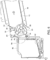
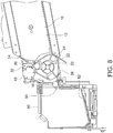
- FIGS. 5 to 8 are side views of the coin-roll ejecting device shown in FIG.
- FIG. 9 is a side view depicting a state in which a bridge phenomenon of the rolls of coins has occurred near the ejecting mechanism in the storing unit of the coin-roll ejecting device shown in FIG. 1 .
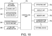
- FIG. 10 is a functional block diagram of a configuration of a control system of the coin-roll ejecting device shown in FIG. 1
- FIGS. 11 and 12 are flowcharts of operations performed by the coin-roll ejecting device shown in FIG. 1
- FIG. 13 is a flowchart of a simpler retry operation and FIG.
- FIG. 14 is a flowchart of a normal retry operation performed by the coin-roll ejecting device shown in FIG. 1 .
- FIG. 15 is a perspective view of a configuration of the money changer that includes the coin-roll ejecting device shown in FIG. 1 .
- a roll of coins processed by the coin-roll ejecting device is shown with a reference letter W.
- the roll of coins stored in the storing unit has not been shown in FIGS. 6 to 8 , and the like.
- a coin-roll ejecting device 1 includes a housing 2 having a substantially cuboidal shape, a plurality of (e.g., six) storing units 10 that are arranged inside the housing 2 one above the other in the vertical direction, and a lifting unit 80 capable of moving in the vertical direction.
- Each of the storing units 10 includes a bottom surface 12 and an ejecting mechanism 19 that ejects the rolls of coins stored in the storing unit one by one from near the bottom surface 12 that is at a lower level with respect to the vertical direction.
- the lifting unit 80 includes a coin-roll storing member 82 in which a roll of coins ejected by the ejecting mechanism 19 of each of the storing units 10 is stored, and an ejected coin-roll detecting unit 84 that detects a roll of coins ejected by the ejecting mechanism 19 of each of the storing units 10. Moreover, a shutter 90 for opening and closing a coin-roll removal opening is arranged on the top surface of the housing 2. When the lifting unit 80 is at an up position (i.e., when the lifting unit 80 is at a position where it is shown with a continuous line in FIG. 1 ), the shutter 90 can be opened and the rolls of coins stored in the coin-roll storing member 82 of the lifting unit 80 can be taken out.
- a controlling unit 70 is arranged in an upper part of the coin-roll ejecting device 1.
- the controlling unit 70 controls the ejecting mechanism 19 of each of the storing units 10 and the lifting unit 80.
- a detailed explanation of various components of the coin-roll ejecting device 1 is given below.
- each of the storing units 10 the rolls of coins are stored on the bottom surface 12 in a piled-up manner and along a rolling direction of the inclined bottom surface 12 with respect to a horizontal plane (i.e., a lower left direction in FIGS. 1 and 5 ).
- the term "to store the rolls of coins in a piled-up manner" includes, based on the number of the rolls of coins stored in the storing unit 10, a situation where the rolls of coins are piled-up in several layers on the bottom surface 12, a situation where the rolls of coins are lined-up in one layer (one row) on the bottom surface 12, or a situation where there is only one roll of coins.
- the rolls of coins may be stored in an orderly and properly aligned manner, or the rolls of coins may be stored in a non-orderly manner though their directions may be aligned. That is, what is meant here is that, though the rolls of coins can be piled-up in several layers, it is not necessary that the rolls of coins are piled-up in several layers, and it is not necessary that the rolls of coins are properly aligned.
- An angle of inclination of the bottom surface 12 of each of the storing units 10 with respect to the horizontal plane is within a range of 8 degrees to 20 degrees.
- the maximum static friction coefficient of the bottom surface 12 of each of the storing units 10 with respect to the roll of coins is within a range of 0.01 to 0.15.
- Each of the storing units 10 includes a pair of side walls that constitutes a storing area for the rolls of coins. At least one of the pair of the side walls constitutes a door that is opened when replenishing the rolls of coins in the storing unit 10 or taking out the rolls of coins from the storing unit 10.
- the side wall of the storing unit 10 that constitutes the door is made from a transparent member or a semi-transparent member, for example, so that an operator can see inside the storing unit 10 through this side wall.
- the door can be provided with a slit, a hole, and the like, to allow the operator to see inside the storing unit 10.
- each of the storing units 10 includes the ejecting mechanism 19 that ejects the rolls of coins one by one from near the bottom surface 12 that is at a lower level with respect to the vertical direction.
- the ejecting mechanism 19 includes a rotating member 20 that rotates around a rotation axis 22 as a shaft center in the counterclockwise direction in FIG. 1 .
- the rotation axis 22 extends horizontally and orthogonally to the direction of inclination of the storing unit 10 (i.e., extends orthogonally to the paper sheet of FIG. 1 ).
- Each of the rotating members 20 is provided with at least two notches 24 (three notches are shown in the example shown in FIG. 1 and the like). Every notch 24 receives one by one the roll of coins stored in the storing unit 10.
- the ejecting mechanism 19 includes a driving unit 21 (see FIG. 2 ) that rotates the rotating member 20 around the rotation axis 22, a rotation position detecting unit 50 that detects a rotating position of the rotating member 20, and a gate unit 30.
- the gate unit 30 is arranged above the rotating member 20. This gate unit 30 prevents a situation where the roll of coins stored in the storing unit 10 does not enter into the notch 24 of the rotating member 20 whereby the roll of coins is ejected from above the rotating member 20.
- the driving unit 21 can rotate the rotating member 20 in both of a forward direction and a reverse direction.
- the forward direction i.e., the counterclockwise direction in FIG. 1
- the reverse direction i.e., the clockwise direction in FIG. 1
- the driving unit 21 can change a rotational speed of the rotating member 20.
- the rotating member 20 is provided with the three notches 24 at an equal interval in the direction of rotation of the rotating member 20 around the rotation axis 22.
- the rotating member 20 is at a rotation position shown in FIG. 3 , one roll of coins among the rolls of coins stored in the storing unit 10 but positioned at the lowest point with respect to the vertical direction on the bottom surface 12 is received in one of the notches 24.
- the rotating member 20 has an outer surface 26 to which the roll of coins stored in the storing unit 10 contacts.
- the outer surface 26 has a shape such that a distance thereof from the center of the rotation axis 22 changes.
- the rotating member 20 has a substantially polygonal shape (substantially triangular in the example shown in FIGS. 3 and 4 ) in a side cross-section.
- the notches 24 are formed near the vertices of the polygon. If a large number of the rolls of coins are stored in the storing unit 10 piled-up in several layers, the rolls of coins stored in the storing unit 10 also contact the outer surface 26 of the rotating member 20.
- the rolls of coins cannot move in the storing unit 10, and though the notch 24 of the rotating member 20 is empty, the roll of coins may not enter the notch 24.
- the distance between the outer surface 26 of the rotating member 20 and the center of the rotation axis 22 is changed. Because this distance is changed, the position of the roll of coins that is in contact with the outer surface 26 when the rotating member 20 is rotated around the rotation axis 22 also changes. Accordingly, because the rolls of coins are stirred and caused to move within the storing unit 10, the roll of coins can be sent in the notch 24 of the rotating member 20.
- the notches 24 of the rotating member 20 are formed such that, when one of the notches 24 of the rotating member 20 is positioned at a storing position (i.e., a position shown in FIG. 3 ), which is a position at which the rotating member 20 is at the rotation position where it is ready to receive the roll of coins from the storing unit 10, an inner wall (shown with a reference number 24a in FIG. 3 ) of this notch 24 and the bottom surface 12 of the storing unit 10 are positioned substantially on one line.
- a storing position i.e., a position shown in FIG. 3
- an inner wall shown with a reference number 24a in FIG. 3
- a shape and a position of each of the notches 24 in the rotating member 20 are set such that, when one notch 24 of the rotating member 20 is positioned at an ejecting position, which is a position at which the rotating member 20 is at the rotation position and ready to eject the roll of coins, other leading notches 24 of this notch 24 are positioned below the bottom surface 12 of the storing unit 10 so that those other leading notches 24 do not receive the rolls of coins from the storing unit 10.
- a length (a length in a depth direction of the rotating member 20 shown in FIG. 2 ) in a longitudinal direction of the rotating member 20 along the rotation axis 22 is larger than 1/2 of the maximum length in a longitudinal direction of the roll of coins that is to be ejected. Accordingly, even if the roll of coins stored in the storing unit 10 is long in the longitudinal direction, the long roll of coins can be ejected surely without losing its balance and stably by the rotating member 20.
- a gear 28 is provided on the rotation axis 22 on a side of the rotating member 20.
- This gear 28 rotates in synchronization with the rotating member 20.
- three to-be-detected members 52 are arranged at an equal interval on a circumference of a rotating member that is provided coaxially with and near the gear 28.
- the rotation position detecting unit 50 that detects each of the to-be-detected members 52 is arranged in a fixed manner near and outside of the gear 28 in a diametrical direction thereof. The rotation position of the rotating member 20 can be detected by the rotation position detecting unit 50 by detecting each of the to-be-detected members 52.
- the rotation position detecting unit 50 is constituted by an optical sensor and the like that includes, for example, a light emitting element and a light receiving element.
- the to-be-detected member 52 is detected because an optical axis between the light emitting element and the light receiving element is blocked by this to-be-detected member 52.
- the gate unit 30 is arranged above the rotating member 20. This gate unit 30 prevents a situation where the roll of coins stored in the storing unit 10 does not enter into the notch 24 of the rotating member 20 whereby the roll of coins is ejected from above the rotating member 20. That is, as shown in FIG. 1 , by blocking a gap between a top surface of the storing unit 10 and the rotating member 20 with the gate unit 30, when a large number of the rolls of coins have been stored in the storing unit 10, it is prevented that the roll of coins is ejected to the lifting unit 80 side from this gap between the top surface of the storing unit 10 and the rotating member 20.
- a swing shaft 32 as a shaft that extends horizontally is provided on upper part of the gate unit 30, and the gate unit 30 is swingable around the swing shaft 32.
- a mechanism to swing the gate unit 30 is explained below.
- a gear 40 that engages with the gear 28 is arranged above the gear 28.
- the gear 40 is rotated around a rotation axis 42 by the driving unit 21. Because teeth provided on a circumference of the gear 28 are engaged with teeth provided on a circumference of the gear 40, the gear 28 rotates following the rotation of the gear 40.
- the rotating member 20 is rotated via the gears 40 and 28 by the driving unit 21.
- a cam 44 is arranged on a side of the gear 40.
- the cam 44 rotates around the rotation axis 42 in synchronization with the gear 40.
- the cam 44 has a substantially quadrangular shape in a cross section.
- each vertex of the cam 44 intermittently pushes a side of the gate unit 30 from the left side in FIGS. 3 and 4 to move the gate unit 30.
- the gate unit 30 swings around the swing shaft 32 between a position at which the gate unit 30 is shown with a continuous line and a position at which the gate unit 30 is shown with a two-dot chain line in FIGS. 3 and 4 .
- the shape of the teeth of the gears 28 and 40 has been omitted from the drawings.
- a swing angle of the gate unit 30 around the swing shaft 32 is, for example, 7 degrees.
- the roll of coins stored in the storing unit 10 when the roll of coins stored in the storing unit 10 is in contact with the gate unit 30, the roll of coins that is pushed and moved by the gate unit 30, or the other rolls of coins in the storing unit 10, may not move smoothly inside the storing unit 10 even if the gate unit 30 is swung.
- the factors that often govern the occurrence of this phenomenon are a distance between the bottom surface 12 of the storing unit 10 and a side surface of the gate unit 30 where the roll of coins contacts the gate unit 30, a diameter of the rolls of coins, and the like.
- one or more mounting members 34 are detachably mounted on the side surface of the gate unit 30 where the roll of coins contacts the gate unit 30.
- These mounting members 34 are arranged such that they can contact the roll of coins stored in the storing unit 10.
- the mounting members 34 allow changing the distance between the bottom surface 12 of the storing unit 10 and the side surface of the gate unit 30 where the roll of coins contacts the gate unit 30. More particularly, as shown in FIG. 2 , a plurality of mounting holes are formed in the side surface of the gate unit 30 where the roll of coins contacts the gate unit 30 and along the direction in which the rotation axis 22 of the rotating member 20 extends. At least one mounting member 34 can be mounted in one of the mounting holes.
- FIGS. 5 to 8 An operation performed by the ejecting mechanism 19, having the above-explained configuration, when ejecting a roll of coins stored in the storing unit 10 is explained below by referring to FIGS. 5 to 8 .
- a storing position which is a position at which the rotating member 20 is at the rotation position and ready to receive the roll of coins from the storing unit 10
- one roll of coins among the rolls of coins stored in the storing unit 10 but positioned at the lowest point with respect to the vertical direction on the bottom surface 12 is received smoothly in this notch 24.
- FIG. 5 when the rotating member 20 is rotated by the driving unit 21 in the counterclockwise direction in FIG.
- the rotating member 20 rotates to an ejecting position shown in FIG. 8 after passing through positions shown in FIGS. 6 and 7 .
- the roll of coins is ejected from the notch 24 of the rotating member 20 to be sent to the coin-roll storing member 82 of the lifting unit 80.
- the roll of coins of which denomination should be stored in which storing unit 10 is set previously.
- this setting it is possible to set such that the rolls of coins of the same denomination are stored in a plurality of the storing units 10.
- the controlling unit 70 of the coin-roll ejecting device 1 explained below, when the setting is made so that the rolls of coins of the same denomination are to be stored in the plurality of the storing units 10, by inputting the total number of the rolls of coins of the same denomination that have been stored in the plurality of the storing units 10 by using a later-explained operating unit 72 and the like, it is possible to perform an inventory management of the rolls of coins of each of the denominations.
- the controlling unit 70 in performing the inventory management of the rolls of coins stored in each of the storing units 10 of the coin-roll ejecting device 1, the controlling unit 70, rather than separately managing the numbers of rolls of coins of JPY 100 stored in these three storing units 10, manages the total number of rolls of coins of JPY 100 stored in all three storing units 10 together. Moreover, when replenishing the rolls of coins of JPY 100 in these three storing units 10, the operator inputs, by using the later-explained operating unit 72, the total number of the rolls of coins of JPY 100 stored in each of these storing units 10.
- the lifting unit 80 is movable up and down, as shown with an arrow in FIG. 1 , between a position at which the lifting unit 80 faces the ejecting mechanism 19 of each of the storing units 10 and an upper position near the shutter 90.
- a lifting unit driving motor 86 that causes the lifting unit 80 to move up and down is arranged inside the housing 2 of the coin-roll ejecting device 1. That is, the lifting unit 80 is driven by the lifting unit driving motor 86.
- the lifting unit 80 is moved to the position facing this ejecting mechanism 19.
- the lifting unit 80 includes the coin-roll storing member 82 in which the roll of coins ejected by the ejecting mechanism 19 of each of the storing units 10 is stored, and the ejected coin-roll detecting unit 84 that detects the roll of coins ejected by the ejecting mechanism 19 of each of the storing units 10.
- the ejected coin-roll detecting unit 84 includes an optical sensor and the like that includes, for example, a light emitting element and a light receiving element.
- the coin-roll ejecting device 1 includes the controlling unit 70.
- the ejecting mechanism 19 (specifically, the driving unit 21 and the rotation position detecting unit 50), the ejected coin-roll detecting unit 84, and the lifting unit driving motor 86 are connected to the controlling unit 70 in a communicable manner. Detection information obtained in each of the rotation position detecting unit 50 and the ejected coin-roll detecting unit 84 are sent to the controlling unit 70.
- the controlling unit 70 sends a command signal to the driving unit 21 and the lifting unit driving motor 86 to control these structural components.
- the operating unit 72 is constituted by, for example, a keyboard that is arranged on a front surface or a top surface of the housing 2.
- the operator can input various pieces of information and commands into the controlling unit 70 by using the operating unit 72.
- the display unit 74 is constituted by, for example, a monitor that is arranged on the front surface or the top surface of the housing 2.
- the information and the like relating to the inventory amount of each of the denominations of the roll of coins stored in each of the storing units 10 and the processing contents of the roll of coins in the coin-roll ejecting device 1 is displayed on the display unit 74.
- an operation and displaying unit such as a touch panel in which the operating unit 72 and the display unit 74 are integrated can be used.
- the information and the like relating to the inventory amount of each of the denominations of the roll of coins stored in each of the storing units 10 and the processing contents of the roll of coins in the coin-roll ejecting device 1 is stored in the memory unit 76.
- the controlling unit 70 can transmit / receive signals via the communication interface unit 78 to / from an external device (for example, specifically, a host device) arranged separately from the coin-roll ejecting device 1.
- FIG. 15 is a perspective view of a configuration of a money changer 100 as the money processing machine that includes the coin-roll ejecting device 1 according to the present embodiment.
- the money changer 100 that includes the coin-roll ejecting device 1 according to the present embodiment has an outer housing 112 with a substantially cuboidal shape.
- the coin-roll ejecting device 1 Inside the outer housing 112, the coin-roll ejecting device 1 according to the present embodiment, a loose-coin depositing and dispensing device 150, and a loose-banknote depositing and dispensing device 160 are arranged side-by-side in a lateral direction.
- An upper door 114 and a lower door 116 are arranged on a front surface of the outer housing 112 of the money changer 100.
- the upper door 114 can be opened upward from its closed state shown in FIG. 15 .
- the lower door 116 can be opened laterally from its closed state shown in FIG. 15 .
- a reference number 152 represents a coin depositing opening used when depositing a loose coin inside a body of the loose-coin depositing and dispensing device 150
- a reference number 154 represents a coin ejection opening for ejecting a loose coin outside the body of the loose-coin depositing and dispensing device 150.
- a reference number 162 represents a banknote depositing opening used when depositing a banknote inside a body of the loose-banknote depositing and dispensing device 160
- a reference number 164 represents a banknote ejection opening for ejecting a banknote outside the body of the loose-banknote depositing and dispensing device 160.
- an operation and displaying unit 140 constituted by, for example, a touch panel and the like, is arranged in the upper door 114 of the money changer 100.
- the operation and displaying unit 140 displays information relating to a processing state, an inventory amount, and the like of the money in each of the devices 1, 150, and 160.
- the operator can input various commands into each of the devices 1, 150, and 160 by operating the operation and displaying unit 140.
- the lifting unit 80 When ejecting a roll of coins from a given storing unit 10 of the coin-roll ejecting device 1 according to the present embodiment, the lifting unit 80 is moved at a position facing the ejecting mechanism 19 of this storing unit 10. Then, the rotating member 20 of this ejecting mechanism 19 is rotated in the ejection direction (specifically, the counterclockwise direction in FIG. 1 ) whereby a roll of coins that had been accommodated in the notch 24 of this rotating member 20 is sent to the coin-roll storing member 82 of the lifting unit 80. In this process, the roll of coins ejected from the storing unit 10 by the ejecting mechanism 19 is detected by the ejected coin-roll detecting unit 84 of the lifting unit 80.
- the controlling unit 70 determines whether the roll of coins is present in the storing unit 10 based on the detection result of the roll of coins obtained by the ejected coin-roll detecting unit 84. Specifically, the controlling unit 70 determines, when rotating the rotating member 20 in the ejection direction of the roll of coins by the driving unit 21 of the ejecting mechanism 19 to cause a predetermined number of the roll of coins to be ejected from the storing unit 10, whether the predetermined number of the roll of coins is detected by the ejected coin-roll detecting unit 84.
- the controlling unit 70 controls, when the predetermined number of the roll of coins is not detected, the driving unit 21 of the ejecting mechanism 19 to perform a retry operation that includes performing once or multiple times a combination of each of an operation to rotate the rotating member 20 in the direction opposite to the ejection direction of the roll of coins and an operation to rotate the rotating member 20 in the ejection direction of the roll of coins.
- the controlling unit 70 determines that no roll of coins has been stored in the storing unit 10 when no roll of coins is detected by the ejected coin-roll detecting unit 84 even when the retry operation has been performed.
- the rolls of coins are stored in the storing unit 10 in the manner shown in FIG. 9 . That is, a plurality of the rolls of coins is involved in a so-called bridge phenomenon between the bottom surface 12 of the storing unit 10 and the gate unit 30. When this happens, the rolls of coins cannot move within the storing unit 10. That is, though the rolls of coins have been stored in the storing unit 10, no roll of coins is sent in the notch 24 of the rotating member 20. In this situation, no roll of coins is detected by the ejected coin-roll detecting unit 84 because no roll of coins is ejected from the storing unit 10 by the ejecting mechanism 19.
- the retry operation of rotating the rotating member 20 in the reverse direction and the forward direction is performed.
- the gate unit 30 is swung following the rotation motion of the rotating member 20. Accordingly, the rolls of coins that are involved in the bridge phenomenon in the storing unit 10 are stirred and caused to move within the storing unit 10 by being pushed and shifted by the gate unit 30. In this manner, even if the rolls of coins are involved in the bridge phenomenon in the storing unit 10 as shown in FIG.
- the rolls of coins that are involved in the bridge phenomenon can be relieved by performing the retry operation. Accordingly, because there is a high possibility that the roll of coins is sent in the notch 24 of the rotating member 20, the roll of coins can be ejected from the storing unit 10 by the ejecting mechanism 19. In this manner, in the present embodiment, the controlling unit 70 determines that no roll of coins has been stored in the storing unit 10 only when no roll of coins is detected by the ejected coin-roll detecting unit 84 even after performing the retry operation.
- a plurality of retry operations is set previously as the retry operation.
- Each of the plurality of retry operations includes a combination of the operation to rotate the rotating member 20 in the direction opposite to the ejection direction of the roll of coins having a different duration and/or times and/or the operation to rotate the rotating member 20 in the ejection direction of the roll of coins having a different duration and/or times.
- the retry operation in the controlling unit 70 are set a simpler retry operation and a normal retry operation.
- the duration and/or times to rotate the rotating member 20 in the direction opposite to the ejection direction of the roll of coins and the duration and/or times to rotate the rotating member 20 in the ejection direction of the roll of coins are shorter/fewer.
- the duration and/or times to rotate the rotating member 20 in the direction opposite to the ejection direction of the roll of coins and the duration and/or times to rotate the rotating member 20 in the ejection direction of the roll of coins are longer/more than those in the simpler retry operation.
- the simpler retry operation and the normal retry operation are explained by using flowcharts shown in FIGS. 13 and 14 .
- the rotating member 20 is rotated in the forward direction (counterclockwise direction in FIG. 1 ) for 3 seconds (STEP102).
- the simpler retry operation when the predetermined number of the roll of coins is not detected by the ejected coin-roll detecting unit 84, by performing the simpler retry operation, it can be determined in about 3.2 seconds whether a roll of coins has been stored in the storing unit 10.
- an operation to stop the rotation of the rotating member 20 after rotating the rotating member 20 in the reverse direction for 0.2 seconds is repeated three times (STEP207), and then the rotating member 20 is rotated in the forward direction for 3 seconds (STEP208).
- an operation to stop the rotation of the rotating member 20 after rotating the rotating member 20 in the reverse direction for 0.2 seconds is repeated four times (STEP209), and then the rotating member 20 is rotated in the forward direction for 3 seconds (STEP210).
- the duration and/or times to rotate the rotating member 20 in the direction opposite to the ejection direction of the roll of coins and the duration and/or times to rotate the rotating member 20 in the ejection direction of the roll of coins are longer/more than those in the simpler retry operation.
- the ejected coin-roll detecting unit 84 when the predetermined number of the roll of coins is not detected by the ejected coin-roll detecting unit 84, by performing the normal retry operation, it can be determined in about 30 seconds whether a roll of coins has been stored in the storing unit 10. Though more time is required to determine whether a roll of coins has been stored in the storing unit 10 in comparison with the simpler retry operation, because the duration and/or times to rotate the rotating member 20 in the forward direction and the reverse direction are longer/more, it can be determined more surely whether a roll of coins has been stored in the storing unit 10.
- the controlling unit 70 determines, upon determining that no roll of coins has been stored in the storing unit 10, based on the performed retry operation, that a current state of the storing unit 10 is one of a plurality of confirmed states including a confirmed empty state and a temporary confirmed empty state. Specifically, the controlling unit 70 determines, upon determining that no roll of coins has been stored in the storing unit 10, that the current state of the storing unit 10 is the confirmed empty state when the normal retry operation has been performed, and that the current state of the storing unit 10 is the temporary confirmed empty state when the simpler retry operation has been performed.
- the information relating to a determination that the storing unit 10 is one of the plurality of the confirmed states including the confirmed empty state and the temporary confirmed empty state is stored in the memory unit 76.
- the controlling unit 70 updates the information relating to the inventory amount of the roll of coins stored in the storing unit 10.
- this information is updated, the information relating to the determination that the storing unit 10 is in one of the plurality of the confirmed states including the confirmed empty state and the temporary confirmed empty state is reset.
- the information relating to the determination that the storing unit 10 is in one of the plurality of the confirmed states including the confirmed empty state and the temporary confirmed empty state is retained in the memory unit 76 until a specific instruction is given to the controlling unit 70 irrespective of whether a power of the coin-roll ejecting device 1 is turned off, a door to access each of the storing units 10 of the coin-roll ejecting device 1 is opened / closed, an entire unit of the storing units 10 is drawn out, and the like.
- the information retained in the memory unit 76 relating to the determination that the storing unit 10 is in one of the plurality of the confirmed states including the confirmed empty state and the temporary confirmed empty state is not reset. This information is retained in the memory unit 76 until the specific instruction is given to the controlling unit 70 (specifically, until the information relating to the inventory amount of the roll of coins stored in the storing unit 10 is updated).
- the controlling unit 70 selects, if the predetermined number of the roll of coins is not detected by the ejected coin-roll detecting unit 84 when the rotating member 20 is rotated by the driving unit 21 of the ejecting mechanism 19 in the ejection direction of the roll of coins, the retry operation to be performed among the plurality of the retry operations set previously (specifically, the simpler retry operation and the normal retry operation) based on whether the predetermined condition is satisfied.
- the "predetermined condition" is that, when the same denomination of the roll of coins is set in a plurality of the storing units 10, and ejecting the roll of coins from the storing unit 10 for which the same denomination has been set.
- the controlling unit 70 When such a "predetermined condition" is satisfied, the controlling unit 70 performs the simpler retry operation as the retry operation, and when this "predetermined condition" is not satisfied, the controlling unit 70 performs the normal retry operation as the retry operation. Moreover, the controlling unit 70 controls, upon determining that the current state of at least one of the storing units 10 for which the same denomination has been set is the confirmed empty state or the temporary confirmed empty state, the ejecting mechanism 19 so that, when ejecting the next roll of coins of the same denomination from the storing unit 10, a roll of coins is ejected in a preferential manner from a storing unit 10 other than the storing unit 10 of which the confirmed state has been determined as the confirmed empty state or the temporary confirmed empty state.
- the controlling unit 70 drives the driving unit 21 of the ejecting mechanism 19 of the storing unit 10 from which the roll of coins that should be ejected from the coin-roll ejecting device 1 is stored. Accordingly, the rotating member 20 is rotated in the ejection direction (the counterclockwise direction in FIG.
- the controlling unit 70 determines that the roll of coins had been stored in the storing unit 10 (STEP6).
- the controlling unit 70 performs the retry operation that includes performing once or multiple times a combination of each of the operation to rotate the rotating member 20 in the direction opposite to the ejection direction of the roll of coins and the operation to rotate the rotating member 20 in the ejection direction of the roll of coins.
- the controlling unit 70 performs the simpler retry operation (STEP4).
- the controlling unit 70 performs the normal retry operation (STEP8).
- the controlling unit 70 performs the simpler retry operation (STEP4), if the roll of coins is detected by the ejected coin-roll detecting unit 84 (STEP5: YES), the controlling unit 70 determines that the roll of coins has been stored in the storing unit 10 (STEP6). Specifically, in this case, it is possible that the rolls of coins involved in the bridge phenomenon that has occurred in the storing unit 10 as shown in FIG. 9 have been separated by the simpler retry operation whereby the roll of coins is sent in the notch 24 of the rotating member 20.
- the controlling unit 70 determines that the the curreent state of the storing unit 10 is the temporary confirmed empty state (STEP7).
- the temporary confirmed empty state means that the storing unit 10 is regarded as empty; however, it also refers to a state in which the possibility that the rolls of coins have been stored in the storing unit 10 but the bridge phenomenon has occurred is higher than the same in the confirmed empty state.
- the controlling unit 70 performs the normal retry operation (STEP8), if the roll of coins is detected by the ejected coin-roll detecting unit 84 (STEP9: YES), the controlling unit 70 determines that the roll of coins has been stored in the storing unit 10 (STEP11). Specifically, in this case, it is possible that the rolls of coins involved in the bridge phenomenon that has occurred in the storing unit 10 as shown in FIG. 9 have been separated by the normal retry operation whereby the roll of coins is sent in the notch 24 of the rotating member 20.
- the controlling unit 70 determines that the curreent state of the storing unit 10 is the confirmed empty state (STEP10).
- the controlling unit 70 When a determination is made by the controlling unit 70 for a given storing unit 10 that it is the confirmed empty state or the temporary confirmed empty state, the information relating to this determination is stored in the memory unit 76. Even if the power of the coin-roll ejecting device 1 is turned off, the door to access each of the storing units 10 of the coin-roll ejecting device 1 is opened / closed, the entire unit of the storing units 10 is drawn out, and the like, the information stored in the memory unit 76 is not reset.
- the controlling unit 70 updates the information relating to the inventory amount of the roll of coins stored in the storing unit 10.
- the information stored in the memory unit 76 relating to the determination that the storing unit 10 is in one of the plurality of the confirmed states including the confirmed empty state and the temporary confirmed empty state is reset.
- the controlling unit 70 determines that the curernt state of the storing unit 10 is the temporary confirmed empty state (STEP7), the controlling unit 70 attempts to eject the roll of coins from other storing unit 10 in which the roll of coins of the same denomination has been stored.
- the controlling unit 70 drives the driving unit 21 of the ejecting mechanism 19 of the other storing unit 10 for which the same denomination of the roll of coins has been set to cause that storing unit 10 to eject the roll of coins (STEP13).
- the controlling unit 70 determines that the current state of all the storing units 10, for which the same denomination of the roll of coins has been set, is the temporary confirmed empty state (STEP12: YES), and when the inventory amount of the roll of coins of that denomination is zero (STEP14: NO), it is possible that no roll of coins of this denomination has been stored in any of the storing units 10 of the coin-roll ejecting device 1.
- the controlling unit 70 stops the operation of the coin-roll ejecting device 1, and causes the display unit 74 (or the operation and displaying unit 140 of the money changer 100) to display a warning message that no roll of coins of this denomination has been stored in the coin-roll ejecting device 1.
- the controlling unit 70 determines that the current state of all the storing units 10, for which the same denomination of the roll of coins has been set, is the temporary confirmed empty state (STEP12: YES), and when the inventory amount of the roll of coins of that denomination is one or more (STEP14: YES), the controlling unit 70 performs the normal retry operation, instead of the simpler retry operation, in all the storing units 10 of that denomination (STEP15).
- the controlling unit 70 has determined that the current state of all the storing units 10, for which the same denomination of the roll of coins has been set, is in the temporary confirmed empty state, in reality, it is possible that the rolls of coins have been stored in at least one of the storing units 10 among the storing units 10 corresponding to this denomination but the bridge phenomenon as shown in FIG. 9 has occurred. In this case, the bridge phenomenon can be relieved by performing the normal retry operation, and the roll of coins may be fed from the storing unit 10 of this denomination.
- the roll of coins is fed in a preferential manner from the storing unit 10 for which it was determined in the earlier ejection operation of the roll of coins that the roll of coins has been stored in the storing unit 10 (i.e., the storing unit 10 that is determined not to be the temporary confirmed empty state or the confirmed empty state).
- the roll of coins is fed in a preferential manner from the storing unit 10 for which it is determined that it is not the temporary confirmed empty state or the confirmed empty state.
- the roll of coins can be surely ejected from the storing unit 10, and the time required to process the roll of coins in the coin-roll ejecting device 1 can be shortened.
- the ejection operation of the roll of coins from the coin-roll ejecting device 1 when performing the ejection operation of the roll of coins from the coin-roll ejecting device 1, if the inventory amount of the roll of coins of that denomination is zero, it is considered that no roll of coins of this denomination has been stored in any of the storing units 10 of the coin-roll ejecting device 1. Instead of performing the ejection operation of the roll of coins from the storing unit 10 by using the ejecting mechanism 19, the warning message that no roll of coins of this denomination has been stored in the coin-roll ejecting device 1 is displayed on the display unit 74 (or the operation and displaying unit 140 of the money changer 100).
- the ejected coin-roll detecting unit 84 that detects the roll of coins ejected from the storing unit 10 by the ejecting mechanism 19 is provided, and the controlling unit 70 determines whether a roll of coins is present in the storing unit 10 based on the detection result of the roll of coins obtained by the ejected coin-roll detecting unit 84. According to this coin-roll ejecting device 1, whether a roll of coins is present in the storing unit 10 can be determined even if no sensor to detect a roll of coins is provided in every storing unit 10 allowing the configuration to be made simpler and the production cost to be reduced.
- the ejected coin-roll detecting unit 84 that detects the roll of coins ejected from the storing unit 10 by the ejecting mechanism 19 is arranged in the coin-roll storing member 82 of the lifting unit 80.
- the controlling unit 70 controls, if the predetermined number of the roll of coins is not detected by the ejected coin-roll detecting unit 84 when the rotating member 20 is rotated by the driving unit 21 in the ejection direction of the roll of coins, the ejecting mechanism 19 to perform the retry operation that includes performing once or multiple times a combination of each of the operation to rotate the rotating member 20 in the direction opposite to the ejection direction of the roll of coins and the operation to rotate the rotating member 20 in the ejection direction of the roll of coins.
- the controlling unit 70 determines that no roll of coins has been stored in the storing unit 10 when no roll of coins is detected by the ejected coin-roll detecting unit 84 even after performing the retry operation. In this case, even if the bridge phenomenon of the rolls of coins has occurred in the storing unit 10 as shown in FIG. 9 , the rolls of coins involved in the bridge phenomenon can be separated by performing the retry operation, and whether a roll of coins has been stored in the storing unit 10 can be determined more precisely.
- the rolls of coins are stored on the bottom surface 12 in a piled-up manner and along the rolling direction of the inclined bottom surface 12 with respect to the horizontal plane.
- the gate unit 30 is arranged above the rotating member 20. This gate unit 30 prevents a situation where the roll of coins stored in the storing unit 10 does not enter into the notches 24 of the rotating member 20 whereby the roll of coins is ejected from above the rotating member 20. Moreover, the gate unit 30 moves following the rotation motion of the rotating member 20. In this case, even if the bridge phenomenon of the rolls of coins has occurred in the storing unit 10 as shown in FIG. 9 , the rolls of coins involved in the bridge phenomenon can be separated by the gate unit 30.
- a plurality of retry operations is set previously in the controlling unit 70 as the retry operation, and each of the plurality of retry operations includes the operation to rotate the rotating member 20 in the direction opposite to the ejection direction of the roll of coins having a different duration and/or times and/or the operation to rotate the rotating member 20 in the ejection direction of the roll of coins having a different duration and/or times.
- the controlling unit 70 selects, if the predetermined number of the roll of coins is not detected by the ejected coin-roll detecting unit 84 when the rotating member 20 is rotated by the driving unit 21 in the ejection direction of the roll of coins, one retry operation among the plurality of the retry operations set previously based on whether a predetermined condition is satisfied as the retry operation to be performed.
- controlling unit 70 are set, as the retry operations, the normal retry operation and the simpler retry operation in which the duration and/or times to rotate the rotating member 20 in the direction opposite to the ejection direction of the roll of coins and the duration and/or times to rotate the rotating member 20 in the ejection direction of the roll of coins are shorter/fewer than those in the normal retry operation.
- the controlling unit 70 determines, upon determining that no roll of coins has been stored in the storing unit 10, that the current state of the storing unit 10 is the confirmed empty state when the normal retry operation has been performed and determines that the current state of the storing unit 10 is the temporary confirmed empty state when the simpler retry operation has been performed.
- the "predetermined condition" is that, when the same denomination of the roll of coins is set in the plurality of the storing units 10, ejecting the roll of coins from the storing unit 10 for which the same denomination has been set.
- a "predetermined condition” is satisfied, in performing the ejection operation of the roll of coins from the plurality of the storing units 10 for which the same denomination has been set, the simpler retry operation has been performed. Accordingly, even if no roll of coins is stored in a certain storing unit 10, the ejection operation of the roll of coins can be performed from another storing unit 10 in a short time.
- the time required to perform the ejection operation of the roll of coins in each of the storing units 10 can be shortened in comparison with the case when the normal retry operation has been performed.
- JPY 100 is set as the denomination of the roll of coins for three storing units 10, and that the rolls of coins of JPY 100 are stored in only one of these storing units 10.
- the ejection operation of the roll of coins is performed sequentially from those storing units 10 for which the roll of coins of JPY 100 has been set.
- the controlling unit 70 controls the ejecting mechanism 19 so that, when ejecting the next roll of coins of the same denomination from the storing unit 10, a roll of coins is ejected in a preferential manner from a storing unit 10 other than the storing unit 10 of which the confirmed state has been determined as the confirmed empty state or the temporary confirmed empty state.
- the roll of coins is fed in a preferential manner from the storing unit 10 for which it is determined that it is not in the temporary confirmed empty state or the confirmed empty state.
- the roll of coins can be surely ejected from the storing unit 10, and the time required to perform the ejection operation of the roll of coins can be shortened.
- the controlling unit 70 when the information relating to the inventory amount of the roll of coins stored in the storing unit 10 is updated, the information relating to the determination that the storing unit 10 is in one of the plurality of the confirmed states including the confirmed empty state and the temporary confirmed empty state is reset.
- the controlling unit 70 when the setting is made so that the rolls of coins of the same denomination are to be stored in the plurality of the storing units 10, by inputting the total number of the rolls of coins of the same denomination that have been stored in the plurality of the storing units 10, it is possible to perform the inventory management of the rolls of coins of each of the denominations.
- the operator replenishes the rolls of coins in the coin-roll ejecting device 1, because there is no need to input the replenished number of the rolls of coins for each of the storing units 10 for which the same denomination has been set, the workload of the operator can be reduced and the convenience can be improved.
- the controlling unit 70 can determine, when ejecting the roll of coins of a given denomination from the storing unit 10, whether the roll of coins is to be ejected from the storing unit 10 based on the inventory amount of the roll of coins of the given denomination. That is, no roll of coins is ejected from the storing unit 10 for which the inventory amount of the roll of coins of the denomination that is about to be ejected from that storing unit 10 is zero. In this manner, waste of time in driving the ejecting mechanism 19 though no roll of coins has been stored in the storing unit 10 can be prevented.
- controlling unit 70 controls, when ejecting the roll of coins of a given denomination from the storing unit 10, if the inventory amount of the roll of coins of that denomination is one or more but it is determined that no roll of coins is stored in any of the storing units 10 corresponding to the denomination, the ejecting mechanism 19 to eject the roll of coins from the storing unit 10 corresponding to the denomination.
- the ejecting mechanism 19 is controlled to eject the roll of coins from the storing unit 10 corresponding to the denomination.
- the information relating to the determination made by the controlling unit 70 that no roll of coins has been stored in the storing unit 10 is stored in the memory unit 76, and the information relating to the determination stored in the memory unit 76 that no roll of coins has been stored in the storing unit 10 is retained until the specific instruction is given to the controlling unit 70.
- the coin-roll ejecting device 1 and the coin-roll ejecting method according to the present embodiment are not limited to the above-explained embodiments and various changes can be made as appropriate.
- the ejected coin-roll detecting unit 84 which detects the roll of coins ejected from the storing unit 10 by the ejecting mechanism 19, is arranged in the coin-roll storing member 82 of the lifting unit 80; however, the configuration is not limited to this example.
- the ejected coin-roll detecting unit which detects the roll of coins ejected from the storing unit 10 by the ejecting mechanism 19, can be arranged at a location other than in the coin-roll storing member 82 of the lifting unit 80.
- the gate unit 30 is swung around a horizontally-extending shaft center following the rotation motion of the rotating member 20 to separate the rolls of coins involved in the bridge phenomenon by the gate unit 30 when the bridge phenomenon of the rolls of coins has occurred in the storing unit 10 as shown in FIG. 9 ; however, the configuration is not limited to this example.
- a mechanism other than the gate unit 30 can be used as the mechanism that separates the rolls of coins involved in the bridge phenomenon occurring in the storing unit 10.
- the gate unit 30 is omitted, because the outer surface 26 of the rotating member 20 is configured so that a distance thereof from the center of the rotation axis 22 as a shaft center changes, the position of the roll of coins that is in contact with the outer surface 26 is shifted when the rotating member 20 rotates around the rotation axis 22. Therefore, if a large number of the rolls of coins have been stored in the storing unit 10 piled-up in several layers, based on a storing state of the rolls of coins in the storing unit 10, the rolls of coins cannot move within the storing unit 10, and the roll of coins may not enter the notch 24 though this notch 24 of the rotating member 20 is empty.
- three or more kinds of retry operations each including the operation to rotate the rotating member 20 in the direction opposite to the ejection direction of the roll of coins having a different duration and/or times and/or the operation to rotate the rotating member 20 in the ejection direction of the roll of coins having a different duration and/or times can be set in the controlling unit 70, and one retry operation among those three or more kinds of the retry operations can be performed.
- the storing unit 10 upon determining that no roll of coins has been stored in the storing unit 10, it can be determined that the storing unit 10 is in one of the plurality of confirmed states having various levels each corresponding to each of the three or more kinds of the retry operations.
Landscapes
- Physics & Mathematics (AREA)
- General Physics & Mathematics (AREA)
- Basic Packing Technique (AREA)
Applications Claiming Priority (2)
| Application Number | Priority Date | Filing Date | Title |
|---|---|---|---|
| JP2014096542A JP2015215662A (ja) | 2014-05-08 | 2014-05-08 | 包装硬貨投出装置、貨幣処理機および包装硬貨投出方法 |
| PCT/JP2015/062390 WO2015170598A1 (fr) | 2014-05-08 | 2015-04-23 | Dispositif de distribution de rouleaux de pièces de monnaie, machine de traitement de monnaie, et procédé de distribution de rouleaux de pièces de monnaie |
Publications (2)
| Publication Number | Publication Date |
|---|---|
| EP3142082A1 true EP3142082A1 (fr) | 2017-03-15 |
| EP3142082A4 EP3142082A4 (fr) | 2018-04-04 |
Family
ID=54392451
Family Applications (1)
| Application Number | Title | Priority Date | Filing Date |
|---|---|---|---|
| EP15789138.3A Withdrawn EP3142082A4 (fr) | 2014-05-08 | 2015-04-23 | Dispositif de distribution de rouleaux de pièces de monnaie, machine de traitement de monnaie, et procédé de distribution de rouleaux de pièces de monnaie |
Country Status (4)
| Country | Link |
|---|---|
| US (1) | US10002482B2 (fr) |
| EP (1) | EP3142082A4 (fr) |
| JP (1) | JP2015215662A (fr) |
| WO (1) | WO2015170598A1 (fr) |
Families Citing this family (1)
| Publication number | Priority date | Publication date | Assignee | Title |
|---|---|---|---|---|
| EP4266271B1 (fr) * | 2022-04-20 | 2024-12-25 | Glory Ltd. | Unité de rouleau de pièces de monnaie |
Family Cites Families (22)
| Publication number | Priority date | Publication date | Assignee | Title |
|---|---|---|---|---|
| US3604432A (en) * | 1969-07-14 | 1971-09-14 | Deering Milliken Res Corp | Coin counter |
| US4469245A (en) * | 1981-06-23 | 1984-09-04 | Casino Technology | Bulk loaded change dispensing apparatus |
| JPS58146987A (ja) * | 1982-02-26 | 1983-09-01 | グローリー工業株式会社 | 物品投出機の投出制御装置 |
| JPH0237080Y2 (fr) * | 1985-09-12 | 1990-10-08 | ||
| US4840290A (en) * | 1986-03-01 | 1989-06-20 | Kabushiki Kaisha Sigma | Bulk loaded coin dispensing machine |
| US4940162A (en) * | 1988-10-17 | 1990-07-10 | Autovend, Inc. | Rolled coin dispenser |
| US5848725A (en) * | 1996-08-15 | 1998-12-15 | Okura Yusoki Kabushiki Kaisha | Picking apparatus |
| US5830055A (en) * | 1996-11-07 | 1998-11-03 | Telequip Corporation | Coin/token canister and ejection mechanism |
| JP3456851B2 (ja) | 1996-12-24 | 2003-10-14 | グローリー工業株式会社 | 棒金検知装置および棒金投出機 |
| EP0996935B1 (fr) * | 1997-04-23 | 2004-09-15 | Jürgen Walter | Distributeur automatique d'argent |
| JPH11259717A (ja) * | 1998-03-11 | 1999-09-24 | Toshiba Corp | 棒金入出金装置 |
| JPH11288479A (ja) * | 1998-04-01 | 1999-10-19 | Toshiba Corp | 棒金処理装置および現金処理装置 |
| US6095369A (en) * | 1998-05-23 | 2000-08-01 | Jenkins; Stuart M. | Coin dispensing apparatus |
| US6206234B1 (en) * | 1998-11-26 | 2001-03-27 | Slim Line Designs Ltd. | Cigar vending machine |
| CA2282104A1 (fr) * | 1999-09-13 | 2001-03-13 | Namsys Inc. | Distributeur de rouleaux de pieces de monnaie et systeme comprenant ce distributeur |
| JP3979820B2 (ja) * | 2001-10-31 | 2007-09-19 | サクサ株式会社 | 棒金払出し装置 |
| US8523641B2 (en) * | 2004-09-15 | 2013-09-03 | Cummins-Allison Corp. | System, method and apparatus for automatically filling a coin cassette |
| EP1879155B1 (fr) * | 2005-03-31 | 2012-12-05 | Glory Ltd. | Systeme de gestion de supplementation de monnaie et conteneur de rouleaux de pieces |
| JP4375279B2 (ja) * | 2005-04-27 | 2009-12-02 | 富士電機リテイルシステムズ株式会社 | 釣銭払出機 |
| US7571833B2 (en) * | 2005-11-30 | 2009-08-11 | Fki Security Products | Bulk coin dispenser |
| US9569912B2 (en) * | 2008-06-26 | 2017-02-14 | Shopatm Bv (Sarl) | Article storage and retrieval apparatus and vending machine |
| EP3079124B1 (fr) * | 2013-12-04 | 2023-02-15 | Glory Ltd. | Dispositif de décharge de paquets de pièces de monnaie |
-
2014
- 2014-05-08 JP JP2014096542A patent/JP2015215662A/ja active Pending
-
2015
- 2015-04-23 WO PCT/JP2015/062390 patent/WO2015170598A1/fr not_active Ceased
- 2015-04-23 US US15/309,386 patent/US10002482B2/en active Active
- 2015-04-23 EP EP15789138.3A patent/EP3142082A4/fr not_active Withdrawn
Also Published As
| Publication number | Publication date |
|---|---|
| WO2015170598A1 (fr) | 2015-11-12 |
| JP2015215662A (ja) | 2015-12-03 |
| US10002482B2 (en) | 2018-06-19 |
| US20170076529A1 (en) | 2017-03-16 |
| EP3142082A4 (fr) | 2018-04-04 |
Similar Documents
| Publication | Publication Date | Title |
|---|---|---|
| EP3079124B1 (fr) | Dispositif de décharge de paquets de pièces de monnaie | |
| US9922484B2 (en) | Coin processing apparatus | |
| EP3142082A1 (fr) | Dispositif de distribution de rouleaux de pièces de monnaie, machine de traitement de monnaie, et procédé de distribution de rouleaux de pièces de monnaie | |
| JP2015108931A (ja) | 両替機 | |
| JP2003208649A (ja) | 棒金払出し装置 | |
| KR101429400B1 (ko) | 확률형 자판기 및 그 구동 장치와 방법 | |
| JP4684710B2 (ja) | 棒金収納庫 | |
| JP2020025823A (ja) | 賞品払出機 | |
| JP5201953B2 (ja) | 開閉扉装置および硬貨取扱機 | |
| JP5063067B2 (ja) | 景品払出機 | |
| JP5033484B2 (ja) | 貨幣放出装置 | |
| CN204856687U (zh) | 包装硬币投出装置 | |
| JP7122846B2 (ja) | 賞品払出機 | |
| JP4874429B2 (ja) | 棒金収納庫 | |
| JP5005824B2 (ja) | 釣銭補充管理システムおよび棒金収納庫 | |
| CN204189223U (zh) | 包装硬币投出装置 | |
| JP4948951B2 (ja) | 景品払出機 | |
| KR102152096B1 (ko) | 코인 튜브 | |
| JP7140471B2 (ja) | 賞品払出装置 | |
| WO2016051943A1 (fr) | Dispositif et procédé pour la distribution de pièces de monnaie emballées | |
| JP5632528B2 (ja) | 棒金収納庫のための制御システム、棒金収納庫、釣銭補充管理システムおよび棒金収納庫のための制御方法 | |
| JP4952041B2 (ja) | 硬貨取扱装置 | |
| WO2015083682A1 (fr) | Dispositif de décharge de paquets de pièces de monnaie | |
| JP5793608B1 (ja) | メダル検出装置及び遊技機 | |
| JP5474918B2 (ja) | 棒金収納庫のための制御システム、棒金収納庫、釣銭補充管理システムおよび棒金収納庫のための制御方法 |
Legal Events
| Date | Code | Title | Description |
|---|---|---|---|
| PUAI | Public reference made under article 153(3) epc to a published international application that has entered the european phase |
Free format text: ORIGINAL CODE: 0009012 |
|
| 17P | Request for examination filed |
Effective date: 20161130 |
|
| AK | Designated contracting states |
Kind code of ref document: A1 Designated state(s): AL AT BE BG CH CY CZ DE DK EE ES FI FR GB GR HR HU IE IS IT LI LT LU LV MC MK MT NL NO PL PT RO RS SE SI SK SM TR |
|
| AX | Request for extension of the european patent |
Extension state: BA ME |
|
| DAV | Request for validation of the european patent (deleted) | ||
| DAX | Request for extension of the european patent (deleted) | ||
| A4 | Supplementary search report drawn up and despatched |
Effective date: 20180302 |
|
| RIC1 | Information provided on ipc code assigned before grant |
Ipc: G07D 9/00 20060101AFI20180226BHEP Ipc: G07D 1/00 20060101ALI20180226BHEP |
|
| STAA | Information on the status of an ep patent application or granted ep patent |
Free format text: STATUS: THE APPLICATION IS DEEMED TO BE WITHDRAWN |
|
| 18D | Application deemed to be withdrawn |
Effective date: 20191101 |