EP3142225A1 - Machine electrique dotee de couplages dans un systeme frigorifique - Google Patents
Machine electrique dotee de couplages dans un systeme frigorifique Download PDFInfo
- Publication number
- EP3142225A1 EP3142225A1 EP15184226.7A EP15184226A EP3142225A1 EP 3142225 A1 EP3142225 A1 EP 3142225A1 EP 15184226 A EP15184226 A EP 15184226A EP 3142225 A1 EP3142225 A1 EP 3142225A1
- Authority
- EP
- European Patent Office
- Prior art keywords
- couplings
- coupling
- electric machine
- cooling
- terminal
- Prior art date
- Legal status (The legal status is an assumption and is not a legal conclusion. Google has not performed a legal analysis and makes no representation as to the accuracy of the status listed.)
- Withdrawn
Links
- 230000008878 coupling Effects 0.000 title claims abstract description 158
- 238000010168 coupling process Methods 0.000 title claims abstract description 158
- 238000005859 coupling reaction Methods 0.000 title claims abstract description 158
- 238000001816 cooling Methods 0.000 title claims abstract description 113
- 238000007789 sealing Methods 0.000 claims description 10
- 238000000034 method Methods 0.000 claims description 9
- 238000004519 manufacturing process Methods 0.000 claims description 7
- 238000004804 winding Methods 0.000 claims description 5
- 239000002826 coolant Substances 0.000 description 9
- RYGMFSIKBFXOCR-UHFFFAOYSA-N Copper Chemical compound [Cu] RYGMFSIKBFXOCR-UHFFFAOYSA-N 0.000 description 7
- 229910052802 copper Inorganic materials 0.000 description 7
- 239000010949 copper Substances 0.000 description 7
- 239000000463 material Substances 0.000 description 6
- 238000004382 potting Methods 0.000 description 5
- 239000000110 cooling liquid Substances 0.000 description 3
- XEEYBQQBJWHFJM-UHFFFAOYSA-N Iron Chemical compound [Fe] XEEYBQQBJWHFJM-UHFFFAOYSA-N 0.000 description 2
- 238000009826 distribution Methods 0.000 description 2
- 239000000956 alloy Substances 0.000 description 1
- 229910045601 alloy Inorganic materials 0.000 description 1
- 229910052782 aluminium Inorganic materials 0.000 description 1
- XAGFODPZIPBFFR-UHFFFAOYSA-N aluminium Chemical compound [Al] XAGFODPZIPBFFR-UHFFFAOYSA-N 0.000 description 1
- 239000012809 cooling fluid Substances 0.000 description 1
- 230000000694 effects Effects 0.000 description 1
- 238000005538 encapsulation Methods 0.000 description 1
- 238000001746 injection moulding Methods 0.000 description 1
- 238000009434 installation Methods 0.000 description 1
- 229910052742 iron Inorganic materials 0.000 description 1
- 238000003475 lamination Methods 0.000 description 1
- 238000005259 measurement Methods 0.000 description 1
- 229910052751 metal Inorganic materials 0.000 description 1
- 239000002184 metal Substances 0.000 description 1
- 239000007769 metal material Substances 0.000 description 1
- 239000012778 molding material Substances 0.000 description 1
- 239000000243 solution Substances 0.000 description 1
- 230000001360 synchronised effect Effects 0.000 description 1
Images



Classifications
-
- H—ELECTRICITY
- H02—GENERATION; CONVERSION OR DISTRIBUTION OF ELECTRIC POWER
- H02K—DYNAMO-ELECTRIC MACHINES
- H02K1/00—Details of the magnetic circuit
- H02K1/06—Details of the magnetic circuit characterised by the shape, form or construction
- H02K1/12—Stationary parts of the magnetic circuit
- H02K1/20—Stationary parts of the magnetic circuit with channels or ducts for flow of cooling medium
-
- H—ELECTRICITY
- H02—GENERATION; CONVERSION OR DISTRIBUTION OF ELECTRIC POWER
- H02K—DYNAMO-ELECTRIC MACHINES
- H02K15/00—Processes or apparatus specially adapted for manufacturing, assembling, maintaining or repairing of dynamo-electric machines
- H02K15/02—Processes or apparatus specially adapted for manufacturing, assembling, maintaining or repairing of dynamo-electric machines of stator or rotor bodies
-
- H—ELECTRICITY
- H02—GENERATION; CONVERSION OR DISTRIBUTION OF ELECTRIC POWER
- H02K—DYNAMO-ELECTRIC MACHINES
- H02K15/00—Processes or apparatus specially adapted for manufacturing, assembling, maintaining or repairing of dynamo-electric machines
- H02K15/06—Embedding prefabricated windings in the machines
-
- H—ELECTRICITY
- H02—GENERATION; CONVERSION OR DISTRIBUTION OF ELECTRIC POWER
- H02K—DYNAMO-ELECTRIC MACHINES
- H02K5/00—Casings; Enclosures; Supports
- H02K5/04—Casings or enclosures characterised by the shape, form or construction thereof
- H02K5/10—Casings or enclosures characterised by the shape, form or construction thereof with arrangements for protection from ingress, e.g. water or fingers
-
- H—ELECTRICITY
- H02—GENERATION; CONVERSION OR DISTRIBUTION OF ELECTRIC POWER
- H02K—DYNAMO-ELECTRIC MACHINES
- H02K9/00—Arrangements for cooling or ventilating
-
- H—ELECTRICITY
- H02—GENERATION; CONVERSION OR DISTRIBUTION OF ELECTRIC POWER
- H02K—DYNAMO-ELECTRIC MACHINES
- H02K9/00—Arrangements for cooling or ventilating
- H02K9/19—Arrangements for cooling or ventilating for machines with closed casing and closed-circuit cooling using a liquid cooling medium, e.g. oil
- H02K9/197—Arrangements for cooling or ventilating for machines with closed casing and closed-circuit cooling using a liquid cooling medium, e.g. oil in which the rotor or stator space is fluid-tight, e.g. to provide for different cooling media for rotor and stator
-
- H—ELECTRICITY
- H02—GENERATION; CONVERSION OR DISTRIBUTION OF ELECTRIC POWER
- H02K—DYNAMO-ELECTRIC MACHINES
- H02K2213/00—Specific aspects, not otherwise provided for and not covered by codes H02K2201/00 - H02K2211/00
- H02K2213/12—Machines characterised by the modularity of some components
Definitions
- the cooling circuit has at least one cooling tube, which extends substantially in the longitudinal extension of the electrical machine.
- the cooling circuit further comprises a first circular, not completely circumferential distribution tube, which spans a plane, wherein the axis of the longitudinal extent of the electric machine is substantially perpendicular to this plane.
- at least one cooling pipe can be connected tightly to the first distribution pipe, wherein the cooling circuit can be flowed through by a coolant.
- An object of the invention is to facilitate the use of cooling tubes for cooling an electrical machine.
- Cooling tubes of an electric machine can be connected with couplings.
- the cooling tubes are, for example, completely, partially or predominantly in a laminated core of the electric machine.
- copper tubes are bent and placed in suitable slots and or passages provided in the lamination stack, or suitable standard parts made of copper or other metallic material are brazed to the tubes.
- the laminated core of the electric machine for example, the laminated core of a stator of the electric machine or the laminated core of a rotor of the electric machine. Since the couplings are part of the cooling of the electrical machine, these are cooling elements for these.
- the electric machine is for example an electric motor or a generator.
- Electrical machines are, for example, synchronous machines or asynchronous machines.
- the electric machine can also be segmented.
- the stator of a segmented electric machine has segments, which each have a laminated core with cooling tubes.
- cooling tubes are located in the laminated core.
- the laminated core is, for example, the laminated core of a primary part or a secondary part.
- the primary part is, for example, a stator and the secondary part, for example, a rotor or rotor.
- the electric machine can be a rotary machine or a linear machine and operated as a motor or as a generator.
- the cooling tubes are for example made of a metal such as copper, iron, aluminum, an alloy, or a temperature-resistant plastic. Through the cooling tubes can be allowed to flow during operation of the electric machine coolant.
- the couplings the cooling pipes can be connected to each other. This can be used to build a cooling system or a cooling circuit.
- the couplings can be made of different materials, or have this. Couplings can in particular have the same materials as the cooling tubes, or even different materials.
- a coupling made of plastic for example, can be produced inexpensively and the design is also easy to implement.
- first coupling of a first coupling type which has a T-shaped branch or a T-shaped form.
- the first coupling type is T-shaped. So he has three openings.
- To connect two cooling tubes at least two couplings are necessary. These two couplings are in particular directly connected to each other and each directly with one of the two cooling tubes. Two adjacent cooling tubes are thus connected or connectable to each other by means of two couplings.
- the couplings form part of the cooling system of the electric machine and are therefore cooling element. Cooling elements for connecting cooling tubes of an electrical machine can be used uniformly for different sizes, in particular different diameters and thus different curvatures of the electric machine. With a few types of couplings, it is therefore possible to connect cooling tubes of different machine sizes.
- the couplings are plugged or plugged onto the cooling tubes.
- the cooling tube or the coupling for example, a seal, so that no coolant can escape.
- the first coupling type has a first terminal, a second terminal and a third terminal.
- the connections can be similar or different in their type.
- a connection type is for example a lancing connection.
- Another type of connection is a screw connection or a flange.
- the first coupling type has plug connections, in particular only plug connections, as the connection. Punctures have a male side and a female side.
- the first coupling type is designed such that the first terminal is a plug-in terminal and the second terminal is a female terminal.
- the plug connection of a coupling can be plugged into the socket connection of a further coupling or be.
- the first terminal of the coupling which is a cooling element
- the second terminal may also be referred to as a first side (A side) and the second terminal as a second side (B side), which is different from the first side.
- One or more couplings may also have a third side (C-side) into which a cooling tube engages.
- C-side third side
- the third page concerns a third connection.
- the connections one, two and three form a kind of T-shape.
- the coupling in addition to a first terminal, a second terminal and a third terminal.
- the third connection is for example a socket connection.
- the third connection can for example be plugged onto a cooling tube.
- the part of the coupling to be patched has the female terminal (this is, for example, the third terminal).
- the cooling tube corresponds to the plug connection.
- the female terminal at least partially surrounds the male terminal.
- a second coupling has a second coupling type.
- the second coupling type has an L-shape. So with the L shape is an elbow can be realized.
- the elbow or the coupling of type two has two connections.
- the first terminal of the second coupling connects, for example, to the cooling tube and the second terminal of the second coupling to a coupling of the first type.
- the first connection is designed, for example, as a socket connection and the second connection as a plug connection.
- the connection types plug connection / socket connection
- the respective first, second, third and further connections of a coupling can also be chosen differently.
- the second or another coupling type has a first terminal, a second terminal and a third terminal.
- the terminals may be made similar or different in type.
- a connection type is for example a lancing connection.
- Another type of connection is a screw connection.
- the second or further coupling type only has connections as a connection. Punctures have a male side and a female side.
- the second or further coupling type can be designed such that the first connection is a plug connection and the second connection is a socket connection.
- the plug connection of a coupling can be plugged into the socket connection of a further coupling or be.
- the different couplings of different types may be at certain positions in the cooling system.
- the position is in particular at least one of the end faces of the laminated core of the electric machine, which is in particular a rotating electrical machine.
- each coupling has a direct connection, ie a direct connection, on at least one cooling tube.
- each coupling of the electric machine as a cooling element has either only an A-side or only a B-side but always a C-side.
- the C-side is used for direct connection of the coupling to the cooling tube.
- this has a third coupling of a third coupling type.
- the third coupling type has an L-shape. With the L-shape, an angle piece can also be realized here.
- the contra-angle has two connections and can cover angles from 0 degrees to 360 degrees, whereby the L-shape is not always recognizable.
- the first terminal of the third coupling of the third coupling type for example, connects to the cooling tube and the second terminal of the third coupling of the third type to a coupling of the first type.
- the second connection of the third type has, in the case of a plug connection, a different type of sterling connection than in the case of the coupling of the type two.
- the coupling of the type three has e.g. only female connectors on and vice versa.
- the choice of plug connection and socket connection at the connections of couplings of different types must be made according to the respective requirements.
- the number of couplings is greater than or equal to the number of cooling tubes. Due to the high number of couplings, it is easy to connect all cooling tubes with a few types of couplings.
- the electric machine has these teeth in or on the laminated core.
- the laminated core therefore has teeth.
- the number of couplings is greater than or equal to the number of teeth of the laminated core.
- Each tooth may also be associated with a cooling tube. A high number of cooling tubes allows a good and uniform cooling of the laminated core.
- the couplings are plugged together.
- the couplings form in a rotary electric machine, for example, a ring structure or even a circle segment.
- Plug-in connections are easy to use in production and not so labor-intensive compared to welded joints.
- the plug connections can also be potted.
- the encapsulation also contributes to the tightness of the connectors.
- an O-ring seals the connection between two couplings or the connection of a coupling and a cooling tube.
- the electric machine have different couplings, these are couplings of the same type or different types, different diameters. This allows the flow rate to be set. The flow rate affects the cooling capacity of the different cooling tubes of the electric machine.
- the electrical machine couplings are shed.
- a winding head can be shed with.
- the potting not only an additional sealing of the couplings with each other or the couplings can be achieved to the cooling tubes, but the potting can also contribute to the cooling of the winding head.
- couplings for different flow rates are interconnected. This allows the cooling capacity to be adjusted. So the cooling capacity depends on the temperature of the coolant. However, the cooling liquid heats up the longer the cooling liquid flows through the cooling tubes in the laminated core.
- the couplings are shed.
- the couplings merge in the region of their plug connections according to a further embodiment of the method.
- the end winding of the stator of the electric machine is cast together with the couplings in a potting.
- the potting can be adjacent to the laminated core, which increases the stability.
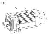
- FIG. 1 shows an electrical machine 1 with a shaft 2 and a plurality of cooling tubes 3 in the laminated core 4.
- the cooling tubes 3 are connected via couplings 40, 41, 42, etc. and part of a cooling system of the electric machine. 1
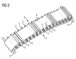
- the representation after FIG. 2 shows a laminated core 4 of an electric machine with teeth 6 and a plurality of cooling tubes 3.
- the laminated core 4 after FIG. 2 is part of a segment motor or generator.
- the laminated core 4 has a first end face 7 and a second end face 8. In the area of the end faces 7 and 8 are located on the cooling tubes 3 stop discs 5. On the stop plates 5 couplings can be set, which in FIG. 2 but not shown.
- the illustrated segment part with the laminated core 4 also has mounting aids 9 and 10.
- FIG. 3 shows a first coupling of a first coupling type 11.
- This coupling of the first type has a first terminal 14 which is a plug-in terminal 26.
- the coupling further comprises a second terminal 17 which is a female terminal 27.
- a plug-in connection 26 of a further coupling can be inserted, since the diameter of the female terminal 27 is greater than the diameter of the plug-in connection 26.
- the coupling of the first type 11 has Further, a third terminal 20.
- the third port 20 is a female connector 27. In these, a cooling tube can be inserted, which in FIG. 3 but not shown.
- the three ports 14, 17 and 20 form a T-shaped branch for cooling fluid.
- FIG. 4 shows a second coupling of a second coupling type 12.
- This coupling of the second type 12 has a first terminal 15, which is a female terminal 27.
- This coupling also has a second connection 18, which is a plug connection 26.
- the female terminal 27 is provided for connection to a cooling pipe. If the cooling tube has a smaller diameter than the connection of the coupling, the cooling tube would be the plug connection.
- the second terminal 18 of the type two is provided for connecting a further coupling of the type 1, for example.
- the second coupling type 12 has an L-shape.
- FIG. 5 shows a third coupling of a third coupling type 13.
- This coupling of the third type like the coupling type 2 has two terminals 16 and 19 on.
- the first terminal 16 of the third coupling type 13 is a female terminal 27. This also applies to the second terminal 19 of the third coupling type 13. At least one of the female terminals is provided for connection to a cooling tube.
- the third coupling type 13 also has an L-shape.
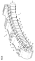
- FIG. 6 shows a laminated core 4 with a plurality of coils 26, 27, 28, 29.
- the plurality of coils 26, 27, 28, 29 forms on the end faces 7 and 8 of the laminated core 4 each have a winding head 22 from.
- the cooling tubes are guided, which in FIG. 6 are not shown.
- the cooling tubes are connected to one another via couplings 30, 31, 32, 40, 41, 42 such that a cooling liquid can be passed through them.
- at least two couplings 30, 31 are mounted on adjacent copper pipes.
- the coupling 30 is of the coupling type three (see FIG. 5 ). With the coupling 30, the coupling 31 is connected.
- the coupling 31 is of the coupling type 1 (see FIG. 3 ).
- the coupling 32 is connected to the coupling 31.
- the coupling 32 is also of the coupling type 1.
- the couplings 30, 31, 32, 33, 40, 41, 42 are part of the cooling system and thus cooling elements. These cooling elements are used to connect cooling tubes of an electrical machine and can be used uniformly for various sizes of electrical machines. This relates in particular to different diameters and thus different curvatures, so that couplings of the same size and the same type can be used in electrical machines of different sizes and shapes.
- the cavity in the cooling elements in which the cooling medium flows is sealed to the environment between the A side of the one cooling element and the B side of the other cooling element with at least one cooling element.
- the sealing element ie the seal 21 may be a 0-ring.
- the sealing element 21 is located in particular centered in a rounding at the end of the B-side of the cooling element. By means of this rounding, a plurality of adjacent cooling elements arranged in a
- the cooling tubes 3 may be made of copper or any other suitable materials.
- the cooling elements can be made of measurement, of injection-molded material or any other suitable materials. For serial production, a production of injection molding materials is possible for reasons of economy.
- the seals 21 disposed in the curves of the B sides of the cooling elements allow the sealing of adjacent cooling elements, i. Couplings, for different curvatures of the cooling system using the same cooling elements. This allows a cost-saving modular system.
- FIG. 9 shows a cooling tube 3 in the laminated core 4 in section.
- the sealing of the couplings 30 and 40 takes place by means of the seals 21. To position the seals 21 serve stop plates. 5
Landscapes
- Engineering & Computer Science (AREA)
- Power Engineering (AREA)
- Manufacturing & Machinery (AREA)
- Motor Or Generator Cooling System (AREA)
- Motor Or Generator Frames (AREA)
Priority Applications (5)
| Application Number | Priority Date | Filing Date | Title |
|---|---|---|---|
| EP15184226.7A EP3142225A1 (fr) | 2015-09-08 | 2015-09-08 | Machine electrique dotee de couplages dans un systeme frigorifique |
| CN201680051801.8A CN108028561B (zh) | 2015-09-08 | 2016-08-16 | 具有在冷却系统中的联接器的电机 |
| EP16753344.7A EP3317946B1 (fr) | 2015-09-08 | 2016-08-16 | Machine electrique dotee de couplages dans un systeme frigorifique |
| US15/757,881 US10749389B2 (en) | 2015-09-08 | 2016-08-16 | Method and electrical machine with couplings in the cooling system |
| PCT/EP2016/069364 WO2017041995A1 (fr) | 2015-09-08 | 2016-08-16 | Moteur électrique muni de raccords dans le système de refroidissement |
Applications Claiming Priority (1)
| Application Number | Priority Date | Filing Date | Title |
|---|---|---|---|
| EP15184226.7A EP3142225A1 (fr) | 2015-09-08 | 2015-09-08 | Machine electrique dotee de couplages dans un systeme frigorifique |
Publications (1)
| Publication Number | Publication Date |
|---|---|
| EP3142225A1 true EP3142225A1 (fr) | 2017-03-15 |
Family
ID=54065792
Family Applications (2)
| Application Number | Title | Priority Date | Filing Date |
|---|---|---|---|
| EP15184226.7A Withdrawn EP3142225A1 (fr) | 2015-09-08 | 2015-09-08 | Machine electrique dotee de couplages dans un systeme frigorifique |
| EP16753344.7A Active EP3317946B1 (fr) | 2015-09-08 | 2016-08-16 | Machine electrique dotee de couplages dans un systeme frigorifique |
Family Applications After (1)
| Application Number | Title | Priority Date | Filing Date |
|---|---|---|---|
| EP16753344.7A Active EP3317946B1 (fr) | 2015-09-08 | 2016-08-16 | Machine electrique dotee de couplages dans un systeme frigorifique |
Country Status (4)
| Country | Link |
|---|---|
| US (1) | US10749389B2 (fr) |
| EP (2) | EP3142225A1 (fr) |
| CN (1) | CN108028561B (fr) |
| WO (1) | WO2017041995A1 (fr) |
Cited By (3)
| Publication number | Priority date | Publication date | Assignee | Title |
|---|---|---|---|---|
| WO2019007880A1 (fr) * | 2017-07-04 | 2019-01-10 | Bayerische Motoren Werke Aktiengesellschaft | Stator pour moteur électrique ainsi que dispositif de refroidissement dudit stator |
| DE102018216525A1 (de) * | 2018-09-27 | 2020-04-02 | Bayerische Motoren Werke Aktiengesellschaft | Kühlvorrichtung für einen Stator einer elektrischen Maschine eines Kraftfahrzeugs, Stator, elektrische Maschine, Kraftfahrzeug sowie Verfahren |
| DE102018130687A1 (de) * | 2018-12-03 | 2020-06-04 | Schlemmer Holding GmbH | Kühlsystem und elektrische Komponente |
Families Citing this family (5)
| Publication number | Priority date | Publication date | Assignee | Title |
|---|---|---|---|---|
| DE102015116811B4 (de) * | 2015-10-02 | 2017-04-13 | Dynamic E Flow Gmbh | Verbindungsstück |
| DE102017218933A1 (de) * | 2017-10-24 | 2019-04-25 | Bayerische Motoren Werke Aktiengesellschaft | Kühlvorrichtung für einen Stator einer elektrischen Maschine eines Kraftfahrzeugs, Stator sowie Kraftfahrzeug |
| CN111697770B (zh) * | 2020-06-08 | 2021-07-06 | 明阳智慧能源集团股份公司 | 半直驱永磁同步风力发电机冷却水管破裂塔上修复方法 |
| BR112023003433A2 (pt) * | 2020-09-30 | 2023-04-11 | Weg Equipamentos Eletricos S/A | Sistema dedicado de arrefecimento a ar para mancais de máquinas elétricas girantes e máquina elétrica girante correspondente |
| WO2024254657A1 (fr) * | 2023-06-13 | 2024-12-19 | Weg Equipamentos Elétricos S.a. | Système de refroidissement pour palier axial |
Citations (6)
| Publication number | Priority date | Publication date | Assignee | Title |
|---|---|---|---|---|
| JPS4718006U (fr) * | 1971-03-31 | 1972-10-31 | ||
| DE19813160A1 (de) | 1997-03-28 | 1998-11-19 | Aisin Seiki | Kühlvorrichtung für einen Elektromotor |
| DE19757605A1 (de) * | 1997-12-23 | 1999-06-24 | Siemens Ag | Elektromotor mit Kühlung |
| DE10131119A1 (de) * | 2001-06-28 | 2003-01-23 | Siemens Linear Motor Systems G | Elektromotor mit Kühlschlange |
| DE102005044832A1 (de) | 2005-09-20 | 2007-03-22 | Siemens Ag | Elektrische Maschine |
| US20140015351A1 (en) * | 2012-07-13 | 2014-01-16 | Lcdrives Corp. | Liquid cooled high efficiency permanent magnet machine with glycol cooling |
Family Cites Families (8)
| Publication number | Priority date | Publication date | Assignee | Title |
|---|---|---|---|---|
| US4080703A (en) * | 1975-08-01 | 1978-03-28 | The Stolle Corporation | Radiating or absorbing heat exchange panel |
| DE10132962A1 (de) * | 2001-07-06 | 2003-01-23 | Rexroth Indramat Gmbh | Kühlvorrichtung eines Elektromotors |
| JP2009261181A (ja) | 2008-04-18 | 2009-11-05 | Toyota Motor Corp | 電動機 |
| CA2736254A1 (fr) * | 2008-09-19 | 2010-03-25 | Martin Mittelmark | Dispositif de micro-irrigation, systeme et procede de purification de l'air interieur par des plantes et bioregeneration par filtre de purification |
| CN201742181U (zh) * | 2010-06-25 | 2011-02-09 | 武汉登奇机电技术有限公司 | 液体冷却管路内嵌式电机 |
| KR101367483B1 (ko) * | 2010-07-06 | 2014-03-12 | 미쓰비시덴키 가부시키가이샤 | 리니어 모터의 전기자 및 리니어 모터 |
| FI124814B (fi) * | 2010-10-18 | 2015-01-30 | Lappeenrannan Teknillinen Yliopisto | Sähkökoneen staattori ja sähkökone |
| CN102931739A (zh) * | 2012-11-23 | 2013-02-13 | 上海中科深江电动车辆有限公司 | 电机定子冷却结构 |
-
2015
- 2015-09-08 EP EP15184226.7A patent/EP3142225A1/fr not_active Withdrawn
-
2016
- 2016-08-16 US US15/757,881 patent/US10749389B2/en active Active
- 2016-08-16 EP EP16753344.7A patent/EP3317946B1/fr active Active
- 2016-08-16 WO PCT/EP2016/069364 patent/WO2017041995A1/fr not_active Ceased
- 2016-08-16 CN CN201680051801.8A patent/CN108028561B/zh active Active
Patent Citations (6)
| Publication number | Priority date | Publication date | Assignee | Title |
|---|---|---|---|---|
| JPS4718006U (fr) * | 1971-03-31 | 1972-10-31 | ||
| DE19813160A1 (de) | 1997-03-28 | 1998-11-19 | Aisin Seiki | Kühlvorrichtung für einen Elektromotor |
| DE19757605A1 (de) * | 1997-12-23 | 1999-06-24 | Siemens Ag | Elektromotor mit Kühlung |
| DE10131119A1 (de) * | 2001-06-28 | 2003-01-23 | Siemens Linear Motor Systems G | Elektromotor mit Kühlschlange |
| DE102005044832A1 (de) | 2005-09-20 | 2007-03-22 | Siemens Ag | Elektrische Maschine |
| US20140015351A1 (en) * | 2012-07-13 | 2014-01-16 | Lcdrives Corp. | Liquid cooled high efficiency permanent magnet machine with glycol cooling |
Cited By (4)
| Publication number | Priority date | Publication date | Assignee | Title |
|---|---|---|---|---|
| WO2019007880A1 (fr) * | 2017-07-04 | 2019-01-10 | Bayerische Motoren Werke Aktiengesellschaft | Stator pour moteur électrique ainsi que dispositif de refroidissement dudit stator |
| US11239712B2 (en) | 2017-07-04 | 2022-02-01 | Bayerische Motoren Werke Aktiengesellschaft | Stator of an electrical machine and cooling apparatus for same |
| DE102018216525A1 (de) * | 2018-09-27 | 2020-04-02 | Bayerische Motoren Werke Aktiengesellschaft | Kühlvorrichtung für einen Stator einer elektrischen Maschine eines Kraftfahrzeugs, Stator, elektrische Maschine, Kraftfahrzeug sowie Verfahren |
| DE102018130687A1 (de) * | 2018-12-03 | 2020-06-04 | Schlemmer Holding GmbH | Kühlsystem und elektrische Komponente |
Also Published As
| Publication number | Publication date |
|---|---|
| US10749389B2 (en) | 2020-08-18 |
| US20180337568A1 (en) | 2018-11-22 |
| EP3317946B1 (fr) | 2019-11-27 |
| CN108028561B (zh) | 2020-12-04 |
| EP3317946A1 (fr) | 2018-05-09 |
| WO2017041995A1 (fr) | 2017-03-16 |
| CN108028561A (zh) | 2018-05-11 |
Similar Documents
| Publication | Publication Date | Title |
|---|---|---|
| EP3317946B1 (fr) | Machine electrique dotee de couplages dans un systeme frigorifique | |
| EP2933901B1 (fr) | Stator d'une machine électrique et sa fabrication | |
| DE112016002113T5 (de) | Isolierharzbeschichtungsverfahren und Stator | |
| EP3127218A1 (fr) | Conducteur creux électrique pour machine électromagnétique | |
| EP3163721A1 (fr) | Machine électrique | |
| DE102012221325A1 (de) | Neuartige Wickelkopf-Kühlung | |
| DE102014201305A1 (de) | Verfahren zur Herstellung eines Statorteils mit einer Hohlleiterspule | |
| AT521063A2 (de) | Stator | |
| DE102014011026B4 (de) | Anschlussvorrichtung und elektrische Maschine | |
| EP3357142A2 (fr) | Composant de machine électrique et machine électrique munie d'au moins un enroulement | |
| WO2021099190A1 (fr) | Système de refroidissement et composant pour une machine électrique à refroidissement par conducteur creux | |
| EP3352341B1 (fr) | Stator et procédé de fabrication d'un stator | |
| DE102021126697A1 (de) | Kurzschlussläufer und Asynchronmaschine mit integrierter Kühlmittelführung, Fertigungsverfahren und Kraftfahrzeug | |
| DE102023201984A1 (de) | Stator einer elektrischen Maschine | |
| DE102019135139A1 (de) | Statorgehäuse für eine elektrische Maschine, elektrische Maschine und Fahrzeug | |
| DE102011108042A1 (de) | Stator für eine elektrische Maschine und Verfahren zu dessen Herstellung | |
| DE102019117832B4 (de) | Stator für eine elektrische Maschine und elektrische Maschine | |
| DE102015211355A1 (de) | Formspule, Wicklungsaufbau sowie Stator eines Generators einer Windenergieanlage und Verfahren zum Herstellen eines Stators | |
| WO2023242164A1 (fr) | Procédé de fabrication d'un composant générateur d'énergie d'une machine électrique tournante et machine électrique tournante | |
| DE102014223421A1 (de) | Maschinenkomponente für eine elektrische Maschine sowie eine elektrische Maschine mit einer Kühleinrichtung | |
| DE102013201320B4 (de) | Verfahren zum Herstellen eines Stators und Stator | |
| DE102015219763A1 (de) | Einteiliges kühlsystem für elektrische maschineund verfahren zur herstellung eines kühlsystems für eine elektrische maschine | |
| DE102015201630A1 (de) | Wicklungsanordnung und elektrische Maschine mit einer derartigen Wicklungsanordnung | |
| DE102016225503A1 (de) | Stator für eine elektrische Rotationsmaschine | |
| DE102021129452B4 (de) | Innengekühlte elektrische Maschine mit einer Hohlleiter-Wicklung und Verfahren zu deren Herstellung |
Legal Events
| Date | Code | Title | Description |
|---|---|---|---|
| PUAI | Public reference made under article 153(3) epc to a published international application that has entered the european phase |
Free format text: ORIGINAL CODE: 0009012 |
|
| AK | Designated contracting states |
Kind code of ref document: A1 Designated state(s): AL AT BE BG CH CY CZ DE DK EE ES FI FR GB GR HR HU IE IS IT LI LT LU LV MC MK MT NL NO PL PT RO RS SE SI SK SM TR |
|
| AX | Request for extension of the european patent |
Extension state: BA ME |
|
| RAP1 | Party data changed (applicant data changed or rights of an application transferred) |
Owner name: SIEMENS AKTIENGESELLSCHAFT |
|
| STAA | Information on the status of an ep patent application or granted ep patent |
Free format text: STATUS: THE APPLICATION IS DEEMED TO BE WITHDRAWN |
|
| 18D | Application deemed to be withdrawn |
Effective date: 20170916 |