EP3142349B1 - Bildgebungsvorrichtung - Google Patents
Bildgebungsvorrichtung Download PDFInfo
- Publication number
- EP3142349B1 EP3142349B1 EP15789651.5A EP15789651A EP3142349B1 EP 3142349 B1 EP3142349 B1 EP 3142349B1 EP 15789651 A EP15789651 A EP 15789651A EP 3142349 B1 EP3142349 B1 EP 3142349B1
- Authority
- EP
- European Patent Office
- Prior art keywords
- display
- viewfinder
- state
- image pickup
- display section
- Prior art date
- Legal status (The legal status is an assumption and is not a legal conclusion. Google has not performed a legal analysis and makes no representation as to the accuracy of the status listed.)
- Active
Links
Images


Classifications
-
- H—ELECTRICITY
- H04—ELECTRIC COMMUNICATION TECHNIQUE
- H04N—PICTORIAL COMMUNICATION, e.g. TELEVISION
- H04N23/00—Cameras or camera modules comprising electronic image sensors; Control thereof
- H04N23/60—Control of cameras or camera modules
- H04N23/63—Control of cameras or camera modules by using electronic viewfinders
- H04N23/633—Control of cameras or camera modules by using electronic viewfinders for displaying additional information relating to control or operation of the camera
-
- G—PHYSICS
- G03—PHOTOGRAPHY; CINEMATOGRAPHY; ANALOGOUS TECHNIQUES USING WAVES OTHER THAN OPTICAL WAVES; ELECTROGRAPHY; HOLOGRAPHY
- G03B—APPARATUS OR ARRANGEMENTS FOR TAKING PHOTOGRAPHS OR FOR PROJECTING OR VIEWING THEM; APPARATUS OR ARRANGEMENTS EMPLOYING ANALOGOUS TECHNIQUES USING WAVES OTHER THAN OPTICAL WAVES; ACCESSORIES THEREFOR
- G03B13/00—Viewfinders; Focusing aids for cameras; Means for focusing for cameras; Autofocus systems for cameras
- G03B13/02—Viewfinders
- G03B13/06—Viewfinders with lenses with or without reflectors
-
- G—PHYSICS
- G03—PHOTOGRAPHY; CINEMATOGRAPHY; ANALOGOUS TECHNIQUES USING WAVES OTHER THAN OPTICAL WAVES; ELECTROGRAPHY; HOLOGRAPHY
- G03B—APPARATUS OR ARRANGEMENTS FOR TAKING PHOTOGRAPHS OR FOR PROJECTING OR VIEWING THEM; APPARATUS OR ARRANGEMENTS EMPLOYING ANALOGOUS TECHNIQUES USING WAVES OTHER THAN OPTICAL WAVES; ACCESSORIES THEREFOR
- G03B15/00—Special procedures for taking photographs; Apparatus therefor
-
- G—PHYSICS
- G03—PHOTOGRAPHY; CINEMATOGRAPHY; ANALOGOUS TECHNIQUES USING WAVES OTHER THAN OPTICAL WAVES; ELECTROGRAPHY; HOLOGRAPHY
- G03B—APPARATUS OR ARRANGEMENTS FOR TAKING PHOTOGRAPHS OR FOR PROJECTING OR VIEWING THEM; APPARATUS OR ARRANGEMENTS EMPLOYING ANALOGOUS TECHNIQUES USING WAVES OTHER THAN OPTICAL WAVES; ACCESSORIES THEREFOR
- G03B17/00—Details of cameras or camera bodies; Accessories therefor
- G03B17/02—Bodies
- G03B17/04—Bodies collapsible, foldable or extensible, e.g. book type
-
- G—PHYSICS
- G03—PHOTOGRAPHY; CINEMATOGRAPHY; ANALOGOUS TECHNIQUES USING WAVES OTHER THAN OPTICAL WAVES; ELECTROGRAPHY; HOLOGRAPHY
- G03B—APPARATUS OR ARRANGEMENTS FOR TAKING PHOTOGRAPHS OR FOR PROJECTING OR VIEWING THEM; APPARATUS OR ARRANGEMENTS EMPLOYING ANALOGOUS TECHNIQUES USING WAVES OTHER THAN OPTICAL WAVES; ACCESSORIES THEREFOR
- G03B17/00—Details of cameras or camera bodies; Accessories therefor
- G03B17/18—Signals indicating condition of a camera member or suitability of light
- G03B17/20—Signals indicating condition of a camera member or suitability of light visible in viewfinder
-
- H—ELECTRICITY
- H04—ELECTRIC COMMUNICATION TECHNIQUE
- H04N—PICTORIAL COMMUNICATION, e.g. TELEVISION
- H04N23/00—Cameras or camera modules comprising electronic image sensors; Control thereof
- H04N23/50—Constructional details
- H04N23/53—Constructional details of electronic viewfinders, e.g. rotatable or detachable
- H04N23/531—Constructional details of electronic viewfinders, e.g. rotatable or detachable being rotatable or detachable
-
- H—ELECTRICITY
- H04—ELECTRIC COMMUNICATION TECHNIQUE
- H04N—PICTORIAL COMMUNICATION, e.g. TELEVISION
- H04N23/00—Cameras or camera modules comprising electronic image sensors; Control thereof
- H04N23/60—Control of cameras or camera modules
- H04N23/64—Computer-aided capture of images, e.g. transfer from script file into camera, check of taken image quality, advice or proposal for image composition or decision on when to take image
-
- H—ELECTRICITY
- H04—ELECTRIC COMMUNICATION TECHNIQUE
- H04N—PICTORIAL COMMUNICATION, e.g. TELEVISION
- H04N23/00—Cameras or camera modules comprising electronic image sensors; Control thereof
- H04N23/60—Control of cameras or camera modules
- H04N23/667—Camera operation mode switching, e.g. between still and video, sport and normal or high- and low-resolution modes
-
- H—ELECTRICITY
- H04—ELECTRIC COMMUNICATION TECHNIQUE
- H04N—PICTORIAL COMMUNICATION, e.g. TELEVISION
- H04N23/00—Cameras or camera modules comprising electronic image sensors; Control thereof
- H04N23/60—Control of cameras or camera modules
- H04N23/61—Control of cameras or camera modules based on recognised objects
Definitions
- the disclosure relates to an image pickup apparatus that is suitable for an apparatus such as a compact digital still camera (DSC).
- DSC compact digital still camera
- An image pickup apparatus with a viewfinder that is foldable along a body or is containable inside the body has been proposed, taking into consideration reduction in size for the sake of convenience in carrying the image pickup apparatus, for example, as disclosed in PTL 1 or PTL 2.
- Such an image pickup apparatus is so configured that a user (a photographer) pulls out the viewfinder in a direction toward the user upon using the viewfinder.
- WO 2013/161583 describes a display controller that includes circuitry configured to cause a display device to display self-portrait photographing information in response to receiving an indication that the display device and an imaging unit are in a predetermined positional relationship.
- An image pickup apparatus provided with a display panel besides a viewfinder is also known.
- the display panel may display information on shooting as an icon, or may display an image such as a so-called live-view image and an image that has been shot.
- Such an image pickup apparatus may include a display panel that is so attached to a body of the image pickup apparatus as to be pivotable on the body.
- a state of the display panel is variable between a first pivoting state in which a display surface is oriented to rear surface side of the body and a second pivoting state in which the display surface is oriented to front surface side of the body.
- Such an image pickup apparatus makes it possible to easily shoot a so-called “selfie”, that is, to direct an image pickup lens toward a photographer oneself to shoot an image of the photographer oneself. This may be achieved due to the second pivoting state in which the display surface of the display panel is oriented to the front surface side, for example. Further, orientation of the body of the image pickup apparatus may be varied from a horizontal state to a vertical state in some cases, when shooting an image such as a selfie using such an image pickup apparatus. In a case where orientation of a component such as the display panel and the body is variable between various states in such a manner, it is preferable to display icons, etc. displayed on the display panel in appropriate positions, an appropriate arrangement, etc., depending on shooting circumstances.
- An image pickup apparatus including: a body; a display section that is pivotable on the body between a first state in which a display surface is oriented to rear surface side of the body and a second state in which the display surface is oriented to front surface side of the body; and a display controller that varies an arrangement state of a predetermined icon depending on orientation of the body, when the display section is in the second state, the predetermined icon being displayed on the display section; and a viewfinder that is contained inside the body and is to be popped up from the body when in use; wherein the display controller varies a display state of the display section depending on a contained state of the viewfinder, when the display section is in the second state.
- the image pickup apparatus of the embodiment of the disclosure has a configuration in which the arrangement state of the predetermined icon displayed on the display section is varied depending on the orientation of the body, when the display surface of the display section is oriented to the front surface side.
- the arrangement state of the predetermined icon displayed on the display section is varied depending on the orientation of the body, when the display surface of the display section is oriented to the front surface side. This makes it possible to perform appropriate information display depending on shooting circumstances.
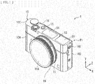
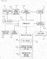
- FIG. 1 illustrates a configuration of an image pickup apparatus 1 according to one embodiment of the disclosure, as viewed from the front.
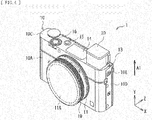
- FIG. 2 illustrates the configuration of the image pickup apparatus 1, as viewed from the back.
- the image pickup apparatus 1 may be a compact digital single-lens camera, for example.
- the image pickup apparatus 1 may include a body 10 and a viewfinder 20. Referring to FIG. 3 , the viewfinder 20 may be contained at a contained position P1 inside the body 10 when the viewfinder 20 is not in use, and may be popped up to a use position P2 outside the body 10 when the viewfinder 20 is in use.
- the body 10 may have an approximate rectangular-parallelepiped shape that is longer in a horizontal direction, for example.
- the body 10 may include a front surface 10A, a rear surface 10B, a top surface 10C, and a side surface 10D, for example.
- a body mount 11 may be provided on the front surface 10A of the body 10. Further, the body 10 may contain, for example, an image pickup device 112 and various control system circuits such as a signal processor 102 illustrated in FIG. 12 describe later.
- a viewfinder operation section 10E may be provided on the side surface 10D of the body 10. The viewfinder operation section 10E may be provided to pop up the viewfinder 20.
- a power button 15 and a shutter button 16 may be provided on the top surface 10C of the body 10.
- a display section 12 may be provided on the rear surface 10B of the body 10.
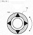
- a plurality of operation buttons 17 and a control wheel 18 may be also provided on the rear surface 10B of the body 10.
- the control wheel 18 may be one of directional selection sections that allow for selection of contents to be displayed on the display section 12 by means of an operation direction. Referring to FIG. 10 , the control wheel 18 may have a function as an operation button 18A that is operable in upward, downward, rightward, and leftward directions, for example.
- the control wheel 18 may also be one of ring-like operation sections that each have an operation direction that is variable between a clockwise direction and a counterclockwise direction.
- the contents to be displayed on the display section 12 such as predetermined shooting information may be selected by means of the operation direction of the control wheel 18, for example.
- an eye sensor 60 may be provided near the viewfinder 20, also on the rear surface 10B of the body 10.
- the eye sensor 60 may detect whether a user (a photographer) is looking into the viewfinder 20, by means of a magnetic sensor, for example.
- the front is front surface side of the body 10, and is lens side or subject side in a front-back direction Z of the body 10.
- the back is rear surface side of the body 10.
- the front-back direction Z may be the same as an optical axis direction of an image pickup lens 111 illustrated in FIG. 12 described later that is attached to the body 10.
- a right-left direction of the body 10 is referred to as an X direction
- a top-bottom direction of the body 10 is referred to as a Y direction.
- the same is applicable to other drawings referred to below.
- the body mount 11 may mechanically or electrically couple the body 10 and the interchangeable image pickup lens 111 illustrated in FIG. 12 described later to each other.
- the user may select the interchangeable image pickup lens 111 depending on its use.
- the selected image pickup lens 111 may be coupled to the body 10. It is to be noted that FIG. 1 illustrates a state in which the body mount 11 is covered with a cap 11A.
- the body mount 11 may be also provided with a control ring 19.
- the control ring 19 may be one of the directional selection sections that allows for selection of contents to be displayed on the display section 12 by means of an operation direction.
- the control ring 19 may also be one of the ring-like operation sections that each have an operation direction that is variable between the clockwise direction and the counterclockwise direction.
- the contents to be displayed on the display section 12 such as predetermined shooting information may be selected by means of the operation direction of the control ring 19, for example.
- the viewfinder 20 may be provided for visually confirming an image to be shot to perform operations such as composition setting and focusing.
- the viewfinder 20 may be an optical viewfinder (OVF) or an electronic viewfinder (EVF).
- OVF optical viewfinder
- EVF electronic viewfinder
- the viewfinder 20 may include an unillustrated eyepiece and an unillustrated display screen behind a viewing window 21 (not illustrated in FIGs. 1 to 3 , see FIG. 7 ).
- the display screen may be a liquid crystal display screen or an organic electroluminescence (EL) display screen, for example.
- the viewfinder 20 may be movable in two or more directions between the contained position P1 at which the viewfinder 20 is contained inside the body 10 and the use position P2 at which the viewfinder 20 is popped up to outside of the body 10. This allows for reduction in size of the image pickup apparatus 1.
- the viewfinder 20 may be preferably movable in two directions that are orthogonal to each other. Specifically, it may be preferable that the viewfinder 20 stretch out upward (be popped up) from the body 10 from the contained position P1 (see FIGs. 1 to 3 ) as illustrated by an arrow A1 in FIGs. 4 and 5 , and be moved backward of the body 10 (in a direction to be closer to the user's eye) as illustrated by an arrow A2 in FIGs. 6 and 7 thereafter to arrive at the use position P2.
- the use position P2 may be located on the upper side of the body 10 by popping up the viewfinder 20 from the body 10.
- the viewfinder 20 may be preferably moved backward of the body 10 by an amount that allows a surface 22A to be in contact with the user's eye of the viewfinder 20 to be located at a position that is farther in the back compared to the rear surface 10B (the display section 12) of the body 10, for example. This reduces the clearance to the user's eye, and decreases possibility that the user's nose hits the display section 12. As a result, usability is improved.
- the body 10 may preferably have an opening 13 on the top surface 10C.
- the viewfinder 20 may be popped out from the body 10 through the opening 13 and may be contained inside the body 10 through the opening 13. This allows for provision of the opening 13, through which the viewfinder 20 is popped up from and contained inside the body 10, at a location other than the rear surface 10B of the body 10. This makes it easier to achieve increase in size of the lens barrel and increase in size of the screen of the display section 12.
- the opening 13 is provided on the rear surface 10B of the body 10
- the size of the lens barrel may be reduced. This may lead to decrease in magnification, brightness, and size of the image pickup device.
- the size of the display section 12 may also be reduced.
- the location of the opening 13 illustrated in FIGs. 1 to 3 may be a location where an electronic flash is arranged in a usual digital single-lens camera.
- An electronic flash 14 in the present embodiment may be located closer to the middle than the opening 13, which is different from the usual location of the electronic flash.
- the viewfinder 20 be so located as to avoid the body mount 11 as illustrated in FIG. 3 described above. This allows for avoidance of interference of the viewfinder 20 with the lens barrel. It is to be noted that the viewfinder 20 may overlap the display section 12 as viewed from the back.
- the viewfinder 20 may be provided with a diopter adjuster 26 as illustrated in FIGs. 6 and 7 .
- the diopter adjuster 26 may be an operation section (such as a lever, a knob, or a dial) for adjusting diopter of the viewfinder 20 depending on eyesight of the user.
- the diopter adjuster 26 may be preferably provided on a top surface of a viewfinder unit that configures the viewfinder 20. Further, the diopter adjuster 26 may be preferably hidden inside the body 10 when the viewfinder 20 is located at the contained position P1 as illustrated in FIGs. 1 to 3 , and may be preferably exposed when the viewfinder 20 is located at the use position P2 as illustrated in FIGs. 6 and 7 .
- the diopter adjuster 26 limits accessibility to the diopter adjuster 26 allows for avoidance of unintentional operation of the diopter adjuster 26 which leads to unintentional change in setting. Further, this reduces an amount of the diopter adjuster 26 that is exposed from the the top surface of the viewfinder unit. This allows for decrease in possibility that the setting is reset due to returning of the viewfinder 20 from the use position P2 to the contained position P1. Thus, troublesome re-adjustment of the diopter adjuster 26 for every use may be eliminated. As a result, it is possible to improve convenience for the user.
- the display section 12 may be a liquid crystal panel, for example.
- the display section 12 may display various pieces of predetermined shooting information that are related to shooting.
- the predetermined shooting information may be a live-view image of a subject 2, icon-like display, etc. as illustrated in FIG. 13 described later.
- the display section 12 may also display various menu display related to the setting of the apparatus, an electronic level, etc.
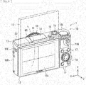
- the display section 12 is pivotable on the body 10 between a first state in which a display surface 12A is oriented to the rear surface side of the body 10 and a second state in which the display surface 12A is oriented to the front surface side of the body 10.
- the display section 12 may be pivotable by 180 degrees on one side of an upper portion of the body 10 as illustrated in FIG. 8 , for example.
- the display section 12 By allowing the display section 12 to be in the second state, it is possible to easily shoot a so-called “selfie”, that is, to direct the image pickup lens 111 ( FIG. 12 ) toward a photographer oneself to shoot an image of the photographer oneself.
- the photographer is allowed to perform shooting while confirming a through view of the subject 2 including the photographer oneself on the display section 12.
- the image pickup apparatus 1 may allow for appropriate selection, depending on preference of the photographer, between shooting with the body 10 oriented horizontally as illustrated in an upper part of FIG. 11 and shooting with the body 10 oriented vertically as illustrated in a lower part of FIG. 11 , in a case such as a case of shooting a selfie.
- FIG. 12 illustrates a configuration example of a control system circuit of the image pickup apparatus 1.
- the image pickup apparatus 1 may include a controller 101, a signal processor 102, a display controller 103, an image recorder 104, an operation section 105, and a sensing section 106, as the control system circuit.
- the image pickup apparatus 1 may further include an image pickup section 110 and a lens driver 113.
- the image pickup section 110 may include the image pickup lens 111 and the image pickup device 112.
- the sensing section 106 may include the eye sensor 60, a display section pivoting sensing section 107, and an orientation sensing section 108.
- the image pickup lens 111 may form an optical image of a subject on the image pickup device 112.
- the image pickup lens 111 may include a plurality of lenses. Factors such as optical zooming magnification and focusing may be adjusted by causing the lenses to travel.
- the image pickup device 112 may form an image of the subject on a light receiving surface through the image pickup lens 111 and generate an electric signal by photoelectric conversion.
- the image pickup device 112 may be a complementary metal oxide semiconductor (CMOS) image sensor, for example.
- CMOS complementary metal oxide semiconductor
- the lens driver 113 may drive the lenses in the image pickup lens 111 for adjusting the factors such as the optical zooming magnification, an F-value, and focusing.
- the signal processor 102 may perform various signal processing on an image pickup signal supplied from the image pickup device 112, thereby generating data such as data of images to be displayed on the viewfinder 20 and the display section 12 and image data to be recorded by the image recorder 104.
- the image recorder 104 may record the image data in an unillustrated recording medium inside the body or an unillustrated recording medium outside the body.
- the operation section 105 may include the power button 15, the shutter button 16, the operation buttons 17, the control wheel 18, the operation button 18A, and the control ring 19, illustrated in FIGs. 1 to 10 described above.
- the controller 101 may perform overall control of the respective sections in the image pickup apparatus 1.
- the controller 101 may have a function as an image pickup controller that performs control depending on a shooting mode.
- One example of the shooting mode may be a self-timer mode in which actual shooting processing is executed after predetermined time has passed since an instruction for starting shooting has been made.
- the display controller 103 may perform display control of the viewfinder 20 and the display section 12.
- the display controller 103 may perform display control of various pieces of shooting information related to shooting that are to be displayed on the viewfinder 20 and the display section 12, for example.
- the display controller 103 may perform control of a live-view image of the subject 2, icon-like display, etc. as illustrated in FIG. 13 .
- the display controller 103 may also perform display control of various menu display related to the setting of the apparatus, the electronic level, etc.
- the display controller 103 may execute display control for displaying text, images, and other various pieces of information on the display section 12, on the basis of the control performed by the controller 101.
- the display section 12 may display the text, the images, and the other various pieces of information, display of which is controlled by the display controller 103.
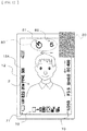
- FIG. 13 illustrates an example in which a group of icons 71, a group of icons 72, a group of icons 73, a self-timer icon 80, and the live-view image of the subject 2 are displayed on the display section 12.
- the self-timer icon 80 may include a shooting mode icon 81 and a countdown icon 82.
- the shooting mode icon 81 may express that the shooting mode is set to the self-timer mode.
- the countdown icon 82 may express passage of time in the self-timer mode.
- the countdown icon 82 may display the passage of time in a countdown style on a second unit basis, for example.
- the display section pivoting sensing section 107 may include a sensor for sensing a state of the display section 12.
- the display section pivoting sensing section 107 may sense at least whether the display section 12 is in the first state (in which the display surface 12A is oriented to the rear surface side) or the second state (in which the display surface 12A is oriented to the front surface side).
- the orientation sensing section 108 may include a sensor for sensing the orientation of the body 10 of the image pickup apparatus 1.
- the sensor for sensing the orientation of the body 10 may be a sensor such as an acceleration sensor and a gyro sensor, for example.
- an angle of the body 10 may be sensed using a sensor such as an angle sensor and a so-called vertical-horizontal sensor, for example.
- the orientation sensing section 108 may sense at least whether the body 10 is oriented horizontally or is oriented vertially.
- the orientation sensing section 108 may also sense a horizontal position in a case of using the electronic level.
- the image pickup apparatus 1 may operate as follows, for example.
- the image pickup apparatus 1 may allow for performing shooting while confirming composition of the subject 2 using one of the viewfinder 20 and the display section 12.
- the image pickup apparatus 1 may be turned on or off by operating the power button 15. Further, in a particular case of using the viewfinder 20, the image pickup apparatus 1 may be turned on or off automatically in accordance with a popping up operation of the viewfinder 20.
- the viewfinder 20 may be contained at the contained position P1 inside the body 10, when the viewfinder 20 is not in use as illustrated in FIGs. 1 to 3 .
- the user may slide the viewfinder operation section 10E provided on the side surface 10D of the body 10. This may pop up the viewfinder unit configuring the viewfinder 20 outside the body 10 as illustrated in FIGs. 4 and 5 .
- the diopter adjuster 26 may be exposed to be operable, when the viewfinder 20 is located at the use position P2.
- the image pickup apparatus 1 may have a configuration in which the viewfinder 20 is movable in two or more directions between the contained position P1 at which the viewfinder 20 is contained inside the body 10 and the use position P2 at which the viewfinder 20 is popped up to outside of the body 10. This allows for provision of the opening 13, through which the viewfinder 20 is popped up from and contained inside the body 10, at a location other than the rear surface 10B of the body 10. This makes it possible to reduce the size of the body 10 while achieving increase in size of the lens barrel and increase in size of the screen of the display section 12.
- the display controller 103 may vary the display state of the display section 12 depending on the contained state of the viewfinder 20, when the display section 12 is in the second state (in which the display surface 12A is oriented to the front surface side).
- a state in which the viewfinder 20 is popped up may refer to a state in which the viewfinder 20 is popped up only on the upper side of the body 10 (in the direction illustrated by the arrow A1 in FIGs. 4 and 5 ), or may refer to a state in which the surface 22A to be in contact with the user's eye is also moved on the rear surface side of the body 10 (in the direction illustrated by the arrow A2 in FIGs. 6 and 7 ) from the foregoing state.
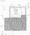
- FIG. 14 illustrates an example of a display region in a case where the display section 12 is in the second state and the viewfinder 20 is popped up.
- the display controller 103 may allow a display region 12B to be a region other than a portion in which the viewfinder 20 overlaps the display section 12 as viewed from the front surface side as illustrated in FIG. 14 , when the display section 12 is in the second state and the viewfinder 20 is popped up from the body 10.
- the live-view image of the subject 2, the icons, etc. may be displayed in the display region 12B.
- FIG. 15 illustrates a display example of the icons in the case where the display section 12 is in the second state and the viewfinder 20 is popped up.
- the display controller 103 may display a plurality of icons in a region other than a portion in which the viewfinder 20 overlaps the display section 12 as viewed from the front surface side as illustrated in a lower part of FIG. 15 , when the display section 12 is in the second state and the viewfinder 20 is popped up from the body 10.
- display positions of the self-timer icon 80 and the group of icons 73 may be so moved that the self-timer icon 80 and the group of icons 73 do not overlap the viewfinder 20 as viewed from the front surface side.
- the display positions of the self-timer icon 80 and the group of icons 73 may be moved from a display state illustrated in an upper part of FIG. 15 to a display state illustrated in the lower part of FIG. 15 , for example.
- the display controller 103 may vary the arrangement state of part of the plurality of icons, as the predetermined icon, depending on the orientation of the body 10, when the display section 12 is in the second state. In this case, the display controller 103 may vary one or both of orientation and a position of the predetermined icon as the arrangement state.
- FIG. 16 illustrates a display example of the icons in a case where the display section 12 is in the second state and the body 10 is oriented vertically as illustrated in the lower part of FIG. 11 .
- the display controller 103 may allow the plurality of icons to be in a first arrangement state in which the plurality of icons are all oriented in the same direction, when the display section 12 is in the second state and the body 10 is oriented horizontally as illustrated in the upper part of FIG. 11 , for example.
- the display controller 103 may allow only part of the icons as the predetermined icon to be in a second arrangement state, when the display section 12 is in the second state and the body 10 is oriented vertically.
- the orientation of the self-timer icon 80 (the shooting-mode icon 81 and the countdown icon 82) as the predetermined icon is so varied in the display example illustrated in FIG. 16 from the display example illustrated in FIG. 13 that the orientation of the self-timer icon 80 is vertical in accordance with the orientation of the body 10.
- FIG. 17 illustrates a display example of the icons in a case where the display section 12 is in the second state, the body 10 is oriented vertically, and the viewfinder 20 is popped up.
- the display controller 103 may display the plurality of icons in a region other than a portion in which the viewfinder 20 overlaps the display section 12 as viewed from the front surface side, when the display section 12 is in the second state and the viewfinder 20 is popped up from the body 10.
- the display positions of the self-timer icon 80 and the group of icons 73 are so varied in the display example illustrated in FIG. 17 from the display example illustrated in FIG. 16 that the self-timer icon 80 and the group of icons 73 do not overlap the viewfinder 20 as viewed from the front surface side.
- FIG. 18 illustrates another display example of the icons in the case where the display section 12 is in the second state, the body 10 is oriented vertically, and the viewfinder 20 is popped up.
- the display position of the self-timer icon 80 is so varied in the display example illustrated in FIG. 18 from the display example illustrated in FIG. 17 that the display position of the self-timer icon 80 is moved from an upper portion of the screen to a lower portion of the screen. It may be preferable that the self-timer icon 80 be so located, for example, in a lower half of the screen as in the display example illustrated in FIG. 18 that the self-timer icon 80 does not disturb confirmation of a state of the subject 2 when shooting a selfie, for example.
- a position of a face of the subject 2 may be detected to display the self-timer icon 80 in a region other than a portion in which the face of the subject 2 is displayed when shooting a selfie, for example.
- the arrangement state of the predetermined icon displayed on the display section 12 may be varied, for example, depending on the orientation of the body 10, when the display surface 12A of the display section 12 is oriented to the front surface side. This makes it possible to perform appropriate information display depending on shooting circumstances.
- the technology may have any of the following configurations.
Landscapes
- Physics & Mathematics (AREA)
- General Physics & Mathematics (AREA)
- Engineering & Computer Science (AREA)
- Multimedia (AREA)
- Signal Processing (AREA)
- Studio Devices (AREA)
- Viewfinders (AREA)
- Indication In Cameras, And Counting Of Exposures (AREA)
Claims (8)
- Bilderfassungsvorrichtung (1), umfassend:einen Körper (10);einen Anzeigeabschnitt (12), der an dem Körper zwischen einem ersten Zustand, in dem eine Anzeigeoberfläche zu einer hinteren Oberflächenseite des Körpers ausgerichtet ist, und einem zweiten Zustand, in dem die Anzeigeoberfläche zu einer vorderen Oberflächenseite des Körpers ausgerichtet ist, schwenkbar ist;eine Anzeigesteuerung (103), die einen Anordnungszustand eines im Voraus bestimmten Symbols in Abhängigkeit von einer Ausrichtung des Körpers variiert, wenn der Anzeigeabschnitt in dem zweiten Zustand ist, wird das im Voraus bestimmte Symbol auf dem Anzeigeabschnitt angezeigt; dadurch gekennzeichnet, dass sie außerdem umfassteinen Sucher (20), der im Inneren des Körpers enthalten ist und im Gebrauch aus dem Körper hochzuklappen ist;wobei die Anzeigesteuerung einen Anzeigezustand der Anzeige in Abhängigkeit von einem enthaltenen Zustand des Suchers variiert, wenn der Anzeigeabschnitt in dem zweiten Zustand ist.
- Bilderfassungsvorrichtung (1) nach Anspruch 1, wobei die Anzeigesteuerung (103) eines oder beides von Ausrichtung und einer Position des im Voraus bestimmten Symbols als den Anordnungszustand variiert.
- Bilderfassungsvorrichtung (1) nach Anspruch 1, wobei die Anzeigesteuerung (103) den Anordnungszustand eines Teils einer Vielzahl von Symbolen als das im Voraus bestimmte Symbol variiert, wobei die Vielzahl von Symbolen auf dem Anzeigeabschnitt angezeigt wird.
- Bilderfassungsvorrichtung (1) nach Anspruch 3, wobei
die Anzeigesteuerung (103) bewirkt, dass die Vielzahl von Symbolen in einem ersten Anordnungszustand ist, in dem die Vielzahl von Symbolen in einer gleichen Richtung ausgerichtet ist, wenn der Anzeigeabschnitt (12) in dem zweiten Zustand ist und die Ausrichtung des Körpers horizontal ist, und
die Anzeigesteuerung bewirkt, dass nur das im Voraus bestimmte Symbol in einem zweiten Anordnungszustand ist, wenn der Anzeigeabschnitt in dem zweiten Zustand ist und die Ausrichtung des Körpers vertikal ist. - Bilderfassungsvorrichtung (1) nach Anspruch 1, ferner umfassend eine Bilderfassungssteuerung (101), die Aufnehmen in einem Selbstauslösermodus durchführt, wobei
das im Voraus bestimmte Symbol ein Rückwärtszählsymbol enthält, das den Verlauf der Zeit im Selbstauslösermodus ausdrückt. - Bilderfassungsvorrichtung (1) nach Anspruch 5, wobei das im Voraus bestimmte Symbol ein Aufnahmemodussymbol enthält, das ausdrückt, dass ein Aufnahmemodus auf den Selbstauslösermodus eingestellt ist.
- Bilderfassungsvorrichtung (1) nach Anspruch 1, wobei die Anzeigesteuerung (103) einer Anzeigeregion gestattet, eine andere Region als ein Abschnitt, in dem der Sucher den Anzeigeabschnitt überlappt, zu sein, wie von der vorderen Oberflächenseite gesehen, wenn der Anzeigeabschnitt in dem zweiten Zustand ist und der Sucher aus dem Körper (10) hochgeklappt ist.
- Bilderfassungsvorrichtung (10) nach Anspruch 1, wobei die Anzeigesteuerung (103) dem im Voraus bestimmten Symbol gestattet, in einer anderen Region als ein Abschnitt, in dem der Sucher den Anzeigeabschnitt überlappt, angezeigt zu werden, wie von der vorderen Oberflächenseite gesehen, wenn der Anzeigeabschnitt (12) in dem zweiten Zustand ist und der Sucher aus dem Körper hochgeklappt ist.
Applications Claiming Priority (3)
| Application Number | Priority Date | Filing Date | Title |
|---|---|---|---|
| JP2014097048 | 2014-05-08 | ||
| JP2014100396 | 2014-05-14 | ||
| PCT/JP2015/058838 WO2015170521A1 (ja) | 2014-05-08 | 2015-03-24 | 撮像装置 |
Publications (3)
| Publication Number | Publication Date |
|---|---|
| EP3142349A1 EP3142349A1 (de) | 2017-03-15 |
| EP3142349A4 EP3142349A4 (de) | 2017-11-15 |
| EP3142349B1 true EP3142349B1 (de) | 2020-01-01 |
Family
ID=54392375
Family Applications (1)
| Application Number | Title | Priority Date | Filing Date |
|---|---|---|---|
| EP15789651.5A Active EP3142349B1 (de) | 2014-05-08 | 2015-03-24 | Bildgebungsvorrichtung |
Country Status (5)
| Country | Link |
|---|---|
| US (1) | US9986168B2 (de) |
| EP (1) | EP3142349B1 (de) |
| JP (1) | JP6515924B2 (de) |
| CN (1) | CN106233709B (de) |
| WO (1) | WO2015170521A1 (de) |
Families Citing this family (5)
| Publication number | Priority date | Publication date | Assignee | Title |
|---|---|---|---|---|
| CN109314745B (zh) * | 2016-05-26 | 2020-09-11 | 富士胶片株式会社 | 摄影装置 |
| US11003050B2 (en) | 2017-09-08 | 2021-05-11 | Hewlett-Packard Development Company, L.P. | Viewfinders with reflective surface |
| JP7191617B2 (ja) * | 2018-09-26 | 2022-12-19 | キヤノン株式会社 | 撮像装置 |
| JP7187236B2 (ja) * | 2018-10-03 | 2022-12-12 | キヤノン株式会社 | 画像観察装置および撮像装置 |
| JP7321886B2 (ja) * | 2019-10-23 | 2023-08-07 | キヤノン株式会社 | 撮像制御装置、その制御方法およびプログラム |
Family Cites Families (20)
| Publication number | Priority date | Publication date | Assignee | Title |
|---|---|---|---|---|
| JPS60121431A (ja) | 1983-12-06 | 1985-06-28 | Fuji Photo Film Co Ltd | ファインダ−ポップアップ型折畳み式カメラ |
| JP4509234B2 (ja) * | 1998-03-11 | 2010-07-21 | 株式会社ニコン | 電子カメラ |
| US7046287B2 (en) * | 1999-12-24 | 2006-05-16 | Nec Corporation | Portable information terminal equipped with camera |
| JP4892125B2 (ja) * | 2000-01-26 | 2012-03-07 | 株式会社ニコン | 電子スチルカメラ |
| JP2001268402A (ja) | 2000-03-17 | 2001-09-28 | Canon Inc | ビューファインダー装置 |
| JP2004266613A (ja) * | 2003-03-03 | 2004-09-24 | Minolta Co Ltd | ファインダ表示装置を備えたカメラ |
| US7583313B2 (en) * | 2003-06-26 | 2009-09-01 | Kyocera Corporation | Imaging apparatus |
| JP2005257869A (ja) * | 2004-03-10 | 2005-09-22 | Canon Inc | 撮像装置 |
| JP2006191302A (ja) * | 2005-01-05 | 2006-07-20 | Toshiba Corp | 電子カメラ装置とその操作案内方法 |
| JP2006325008A (ja) * | 2005-05-19 | 2006-11-30 | Sharp Corp | 撮像装置 |
| JP2008053925A (ja) | 2006-08-23 | 2008-03-06 | Nikon Corp | 撮影装置 |
| JP2010103921A (ja) * | 2008-10-27 | 2010-05-06 | Olympus Imaging Corp | 撮像装置および撮像装置の制御方法 |
| KR101567812B1 (ko) * | 2008-12-31 | 2015-11-11 | 삼성전자주식회사 | 지능형 셀프 타이머 모드를 지원하는 디지털 카메라 및 그 제어방법 |
| JP5516882B2 (ja) * | 2010-07-29 | 2014-06-11 | セイコーエプソン株式会社 | プログラム、情報記憶媒体、端末装置、表示システムおよび画像生成方法 |
| JP5557780B2 (ja) * | 2011-03-25 | 2014-07-23 | 株式会社Nttドコモ | 携帯端末および画面表示変更方法 |
| KR101795603B1 (ko) * | 2011-11-17 | 2017-12-01 | 삼성전자주식회사 | 디지털 촬영 장치 및 그 제어방법 |
| JP5970937B2 (ja) * | 2012-04-25 | 2016-08-17 | ソニー株式会社 | 表示制御装置および表示制御方法 |
| JP5969847B2 (ja) | 2012-07-19 | 2016-08-17 | オリンパス株式会社 | 撮像装置 |
| JP2014123896A (ja) * | 2012-12-21 | 2014-07-03 | Olympus Imaging Corp | 撮像装置、撮像方法、及びプログラム |
| US9413968B2 (en) * | 2013-04-04 | 2016-08-09 | Samsung Electronics Co., Ltd. | Camera apparatus and wireless communication terminal including the same |
-
2015
- 2015-03-24 JP JP2016517838A patent/JP6515924B2/ja active Active
- 2015-03-24 US US15/306,948 patent/US9986168B2/en active Active
- 2015-03-24 EP EP15789651.5A patent/EP3142349B1/de active Active
- 2015-03-24 CN CN201580021507.8A patent/CN106233709B/zh not_active Expired - Fee Related
- 2015-03-24 WO PCT/JP2015/058838 patent/WO2015170521A1/ja not_active Ceased
Non-Patent Citations (1)
| Title |
|---|
| None * |
Also Published As
| Publication number | Publication date |
|---|---|
| CN106233709B (zh) | 2020-12-01 |
| EP3142349A4 (de) | 2017-11-15 |
| WO2015170521A1 (ja) | 2015-11-12 |
| JP6515924B2 (ja) | 2019-05-22 |
| JPWO2015170521A1 (ja) | 2017-04-20 |
| US20170054914A1 (en) | 2017-02-23 |
| US9986168B2 (en) | 2018-05-29 |
| EP3142349A1 (de) | 2017-03-15 |
| CN106233709A (zh) | 2016-12-14 |
Similar Documents
| Publication | Publication Date | Title |
|---|---|---|
| US8605188B2 (en) | Camera having a rear-surface display section and an in-viewfinder display section | |
| US10623647B2 (en) | Image capturing apparatus and control method for changing a setting based on a touch operation on a display | |
| JP4991621B2 (ja) | 撮像装置 | |
| EP3142349B1 (de) | Bildgebungsvorrichtung | |
| US12513278B2 (en) | Imaging apparatus, control method of imaging apparatus, and non-transitory computer readable medium | |
| US9172881B2 (en) | Camera and method of controlling operation of same | |
| KR102078063B1 (ko) | 전자기기 및 그 제어 방법 | |
| US20130249836A1 (en) | Display control apparatus and control method of display control apparatus | |
| US12406330B2 (en) | Electronic apparatus, control method of electronic apparatus, and non-transitory computer readable medium | |
| US10291856B2 (en) | Image capturing apparatus having self-image display mode, and control therefor | |
| US20250088735A1 (en) | Image pickup apparatus, control method, and storage medium | |
| US10097762B2 (en) | Imaging unit to control display state of shooting information | |
| US9143694B2 (en) | Camera and method of controlling operation of same | |
| JP2014150508A (ja) | 撮像装置 | |
| JP5969847B2 (ja) | 撮像装置 | |
| JP5615086B2 (ja) | 撮像装置、その制御方法及びプログラム | |
| US20240406366A1 (en) | Imaging apparatus, control method of imaging apparatus, and non-transitory computer readable medium | |
| US12335605B2 (en) | Image processing device, imaging device, method for controlling image processing device, and storage medium | |
| JPH11352389A (ja) | 電子ファインダカメラ | |
| US20250166120A1 (en) | Electronic device, control method of electronic device, and non-transitory computer readable medium | |
| US9667876B2 (en) | Image capturing apparatus and control method of the same | |
| KR20140091117A (ko) | 촬영 장치 및 촬영 장치의 라이브 뷰 표시 방법 | |
| JP2019020441A (ja) | 撮像装置、その制御方法、およびプログラム、並びに記憶媒体 |
Legal Events
| Date | Code | Title | Description |
|---|---|---|---|
| STAA | Information on the status of an ep patent application or granted ep patent |
Free format text: STATUS: THE INTERNATIONAL PUBLICATION HAS BEEN MADE |
|
| PUAI | Public reference made under article 153(3) epc to a published international application that has entered the european phase |
Free format text: ORIGINAL CODE: 0009012 |
|
| STAA | Information on the status of an ep patent application or granted ep patent |
Free format text: STATUS: REQUEST FOR EXAMINATION WAS MADE |
|
| 17P | Request for examination filed |
Effective date: 20161003 |
|
| AK | Designated contracting states |
Kind code of ref document: A1 Designated state(s): AL AT BE BG CH CY CZ DE DK EE ES FI FR GB GR HR HU IE IS IT LI LT LU LV MC MK MT NL NO PL PT RO RS SE SI SK SM TR |
|
| AX | Request for extension of the european patent |
Extension state: BA ME |
|
| DAV | Request for validation of the european patent (deleted) | ||
| DAX | Request for extension of the european patent (deleted) | ||
| A4 | Supplementary search report drawn up and despatched |
Effective date: 20170914 |
|
| RIC1 | Information provided on ipc code assigned before grant |
Ipc: G03B 17/18 20060101ALI20170908BHEP Ipc: G03B 17/04 20060101ALI20170908BHEP Ipc: G03B 17/20 20060101ALI20170908BHEP Ipc: G03B 15/00 20060101ALI20170908BHEP Ipc: H04N 5/232 20060101ALI20170908BHEP Ipc: H04N 5/225 20060101AFI20170908BHEP Ipc: G03B 13/06 20060101ALI20170908BHEP |
|
| RA4 | Supplementary search report drawn up and despatched (corrected) |
Effective date: 20171016 |
|
| STAA | Information on the status of an ep patent application or granted ep patent |
Free format text: STATUS: EXAMINATION IS IN PROGRESS |
|
| 17Q | First examination report despatched |
Effective date: 20181123 |
|
| GRAP | Despatch of communication of intention to grant a patent |
Free format text: ORIGINAL CODE: EPIDOSNIGR1 |
|
| STAA | Information on the status of an ep patent application or granted ep patent |
Free format text: STATUS: GRANT OF PATENT IS INTENDED |
|
| INTG | Intention to grant announced |
Effective date: 20190805 |
|
| GRAS | Grant fee paid |
Free format text: ORIGINAL CODE: EPIDOSNIGR3 |
|
| GRAA | (expected) grant |
Free format text: ORIGINAL CODE: 0009210 |
|
| STAA | Information on the status of an ep patent application or granted ep patent |
Free format text: STATUS: THE PATENT HAS BEEN GRANTED |
|
| AK | Designated contracting states |
Kind code of ref document: B1 Designated state(s): AL AT BE BG CH CY CZ DE DK EE ES FI FR GB GR HR HU IE IS IT LI LT LU LV MC MK MT NL NO PL PT RO RS SE SI SK SM TR |
|
| REG | Reference to a national code |
Ref country code: GB Ref legal event code: FG4D |
|
| REG | Reference to a national code |
Ref country code: CH Ref legal event code: EP Ref country code: AT Ref legal event code: REF Ref document number: 1221291 Country of ref document: AT Kind code of ref document: T Effective date: 20200115 |
|
| REG | Reference to a national code |
Ref country code: IE Ref legal event code: FG4D |
|
| REG | Reference to a national code |
Ref country code: DE Ref legal event code: R096 Ref document number: 602015044773 Country of ref document: DE |
|
| REG | Reference to a national code |
Ref country code: NL Ref legal event code: MP Effective date: 20200101 |
|
| REG | Reference to a national code |
Ref country code: LT Ref legal event code: MG4D |
|
| PG25 | Lapsed in a contracting state [announced via postgrant information from national office to epo] |
Ref country code: NL Free format text: LAPSE BECAUSE OF FAILURE TO SUBMIT A TRANSLATION OF THE DESCRIPTION OR TO PAY THE FEE WITHIN THE PRESCRIBED TIME-LIMIT Effective date: 20200101 Ref country code: LT Free format text: LAPSE BECAUSE OF FAILURE TO SUBMIT A TRANSLATION OF THE DESCRIPTION OR TO PAY THE FEE WITHIN THE PRESCRIBED TIME-LIMIT Effective date: 20200101 Ref country code: RS Free format text: LAPSE BECAUSE OF FAILURE TO SUBMIT A TRANSLATION OF THE DESCRIPTION OR TO PAY THE FEE WITHIN THE PRESCRIBED TIME-LIMIT Effective date: 20200101 Ref country code: NO Free format text: LAPSE BECAUSE OF FAILURE TO SUBMIT A TRANSLATION OF THE DESCRIPTION OR TO PAY THE FEE WITHIN THE PRESCRIBED TIME-LIMIT Effective date: 20200401 Ref country code: FI Free format text: LAPSE BECAUSE OF FAILURE TO SUBMIT A TRANSLATION OF THE DESCRIPTION OR TO PAY THE FEE WITHIN THE PRESCRIBED TIME-LIMIT Effective date: 20200101 Ref country code: CZ Free format text: LAPSE BECAUSE OF FAILURE TO SUBMIT A TRANSLATION OF THE DESCRIPTION OR TO PAY THE FEE WITHIN THE PRESCRIBED TIME-LIMIT Effective date: 20200101 Ref country code: PT Free format text: LAPSE BECAUSE OF FAILURE TO SUBMIT A TRANSLATION OF THE DESCRIPTION OR TO PAY THE FEE WITHIN THE PRESCRIBED TIME-LIMIT Effective date: 20200527 |
|
| PG25 | Lapsed in a contracting state [announced via postgrant information from national office to epo] |
Ref country code: LV Free format text: LAPSE BECAUSE OF FAILURE TO SUBMIT A TRANSLATION OF THE DESCRIPTION OR TO PAY THE FEE WITHIN THE PRESCRIBED TIME-LIMIT Effective date: 20200101 Ref country code: SE Free format text: LAPSE BECAUSE OF FAILURE TO SUBMIT A TRANSLATION OF THE DESCRIPTION OR TO PAY THE FEE WITHIN THE PRESCRIBED TIME-LIMIT Effective date: 20200101 Ref country code: HR Free format text: LAPSE BECAUSE OF FAILURE TO SUBMIT A TRANSLATION OF THE DESCRIPTION OR TO PAY THE FEE WITHIN THE PRESCRIBED TIME-LIMIT Effective date: 20200101 Ref country code: GR Free format text: LAPSE BECAUSE OF FAILURE TO SUBMIT A TRANSLATION OF THE DESCRIPTION OR TO PAY THE FEE WITHIN THE PRESCRIBED TIME-LIMIT Effective date: 20200402 Ref country code: IS Free format text: LAPSE BECAUSE OF FAILURE TO SUBMIT A TRANSLATION OF THE DESCRIPTION OR TO PAY THE FEE WITHIN THE PRESCRIBED TIME-LIMIT Effective date: 20200501 Ref country code: BG Free format text: LAPSE BECAUSE OF FAILURE TO SUBMIT A TRANSLATION OF THE DESCRIPTION OR TO PAY THE FEE WITHIN THE PRESCRIBED TIME-LIMIT Effective date: 20200401 |
|
| REG | Reference to a national code |
Ref country code: DE Ref legal event code: R097 Ref document number: 602015044773 Country of ref document: DE |
|
| PG25 | Lapsed in a contracting state [announced via postgrant information from national office to epo] |
Ref country code: RO Free format text: LAPSE BECAUSE OF FAILURE TO SUBMIT A TRANSLATION OF THE DESCRIPTION OR TO PAY THE FEE WITHIN THE PRESCRIBED TIME-LIMIT Effective date: 20200101 Ref country code: SK Free format text: LAPSE BECAUSE OF FAILURE TO SUBMIT A TRANSLATION OF THE DESCRIPTION OR TO PAY THE FEE WITHIN THE PRESCRIBED TIME-LIMIT Effective date: 20200101 Ref country code: ES Free format text: LAPSE BECAUSE OF FAILURE TO SUBMIT A TRANSLATION OF THE DESCRIPTION OR TO PAY THE FEE WITHIN THE PRESCRIBED TIME-LIMIT Effective date: 20200101 Ref country code: MC Free format text: LAPSE BECAUSE OF FAILURE TO SUBMIT A TRANSLATION OF THE DESCRIPTION OR TO PAY THE FEE WITHIN THE PRESCRIBED TIME-LIMIT Effective date: 20200101 Ref country code: EE Free format text: LAPSE BECAUSE OF FAILURE TO SUBMIT A TRANSLATION OF THE DESCRIPTION OR TO PAY THE FEE WITHIN THE PRESCRIBED TIME-LIMIT Effective date: 20200101 Ref country code: SM Free format text: LAPSE BECAUSE OF FAILURE TO SUBMIT A TRANSLATION OF THE DESCRIPTION OR TO PAY THE FEE WITHIN THE PRESCRIBED TIME-LIMIT Effective date: 20200101 Ref country code: DK Free format text: LAPSE BECAUSE OF FAILURE TO SUBMIT A TRANSLATION OF THE DESCRIPTION OR TO PAY THE FEE WITHIN THE PRESCRIBED TIME-LIMIT Effective date: 20200101 |
|
| REG | Reference to a national code |
Ref country code: CH Ref legal event code: PL |
|
| PLBE | No opposition filed within time limit |
Free format text: ORIGINAL CODE: 0009261 |
|
| STAA | Information on the status of an ep patent application or granted ep patent |
Free format text: STATUS: NO OPPOSITION FILED WITHIN TIME LIMIT |
|
| REG | Reference to a national code |
Ref country code: AT Ref legal event code: MK05 Ref document number: 1221291 Country of ref document: AT Kind code of ref document: T Effective date: 20200101 |
|
| 26N | No opposition filed |
Effective date: 20201002 |
|
| REG | Reference to a national code |
Ref country code: BE Ref legal event code: MM Effective date: 20200331 |
|
| PG25 | Lapsed in a contracting state [announced via postgrant information from national office to epo] |
Ref country code: LU Free format text: LAPSE BECAUSE OF NON-PAYMENT OF DUE FEES Effective date: 20200324 |
|
| PG25 | Lapsed in a contracting state [announced via postgrant information from national office to epo] |
Ref country code: IE Free format text: LAPSE BECAUSE OF NON-PAYMENT OF DUE FEES Effective date: 20200324 Ref country code: FR Free format text: LAPSE BECAUSE OF NON-PAYMENT OF DUE FEES Effective date: 20200331 Ref country code: LI Free format text: LAPSE BECAUSE OF NON-PAYMENT OF DUE FEES Effective date: 20200331 Ref country code: AT Free format text: LAPSE BECAUSE OF FAILURE TO SUBMIT A TRANSLATION OF THE DESCRIPTION OR TO PAY THE FEE WITHIN THE PRESCRIBED TIME-LIMIT Effective date: 20200101 Ref country code: CH Free format text: LAPSE BECAUSE OF NON-PAYMENT OF DUE FEES Effective date: 20200331 Ref country code: IT Free format text: LAPSE BECAUSE OF FAILURE TO SUBMIT A TRANSLATION OF THE DESCRIPTION OR TO PAY THE FEE WITHIN THE PRESCRIBED TIME-LIMIT Effective date: 20200101 |
|
| PG25 | Lapsed in a contracting state [announced via postgrant information from national office to epo] |
Ref country code: SI Free format text: LAPSE BECAUSE OF FAILURE TO SUBMIT A TRANSLATION OF THE DESCRIPTION OR TO PAY THE FEE WITHIN THE PRESCRIBED TIME-LIMIT Effective date: 20200101 Ref country code: BE Free format text: LAPSE BECAUSE OF NON-PAYMENT OF DUE FEES Effective date: 20200331 Ref country code: PL Free format text: LAPSE BECAUSE OF FAILURE TO SUBMIT A TRANSLATION OF THE DESCRIPTION OR TO PAY THE FEE WITHIN THE PRESCRIBED TIME-LIMIT Effective date: 20200101 |
|
| GBPC | Gb: european patent ceased through non-payment of renewal fee |
Effective date: 20200401 |
|
| PG25 | Lapsed in a contracting state [announced via postgrant information from national office to epo] |
Ref country code: GB Free format text: LAPSE BECAUSE OF NON-PAYMENT OF DUE FEES Effective date: 20200401 |
|
| PG25 | Lapsed in a contracting state [announced via postgrant information from national office to epo] |
Ref country code: TR Free format text: LAPSE BECAUSE OF FAILURE TO SUBMIT A TRANSLATION OF THE DESCRIPTION OR TO PAY THE FEE WITHIN THE PRESCRIBED TIME-LIMIT Effective date: 20200101 Ref country code: MT Free format text: LAPSE BECAUSE OF FAILURE TO SUBMIT A TRANSLATION OF THE DESCRIPTION OR TO PAY THE FEE WITHIN THE PRESCRIBED TIME-LIMIT Effective date: 20200101 Ref country code: CY Free format text: LAPSE BECAUSE OF FAILURE TO SUBMIT A TRANSLATION OF THE DESCRIPTION OR TO PAY THE FEE WITHIN THE PRESCRIBED TIME-LIMIT Effective date: 20200101 |
|
| PG25 | Lapsed in a contracting state [announced via postgrant information from national office to epo] |
Ref country code: MK Free format text: LAPSE BECAUSE OF FAILURE TO SUBMIT A TRANSLATION OF THE DESCRIPTION OR TO PAY THE FEE WITHIN THE PRESCRIBED TIME-LIMIT Effective date: 20200101 Ref country code: AL Free format text: LAPSE BECAUSE OF FAILURE TO SUBMIT A TRANSLATION OF THE DESCRIPTION OR TO PAY THE FEE WITHIN THE PRESCRIBED TIME-LIMIT Effective date: 20200101 |
|
| REG | Reference to a national code |
Ref country code: DE Ref legal event code: R079 Ref document number: 602015044773 Country of ref document: DE Free format text: PREVIOUS MAIN CLASS: H04N0005225000 Ipc: H04N0023000000 |
|
| PGFP | Annual fee paid to national office [announced via postgrant information from national office to epo] |
Ref country code: DE Payment date: 20230221 Year of fee payment: 9 |
|
| P01 | Opt-out of the competence of the unified patent court (upc) registered |
Effective date: 20230527 |
|
| REG | Reference to a national code |
Ref country code: DE Ref legal event code: R119 Ref document number: 602015044773 Country of ref document: DE |
|
| PG25 | Lapsed in a contracting state [announced via postgrant information from national office to epo] |
Ref country code: DE Free format text: LAPSE BECAUSE OF NON-PAYMENT OF DUE FEES Effective date: 20241001 |
|
| PG25 | Lapsed in a contracting state [announced via postgrant information from national office to epo] |
Ref country code: DE Free format text: LAPSE BECAUSE OF NON-PAYMENT OF DUE FEES Effective date: 20241001 |