EP3142459A1 - Benutzerendgerät und kommunikationssteuerungsverfahren - Google Patents
Benutzerendgerät und kommunikationssteuerungsverfahren Download PDFInfo
- Publication number
- EP3142459A1 EP3142459A1 EP15789247.2A EP15789247A EP3142459A1 EP 3142459 A1 EP3142459 A1 EP 3142459A1 EP 15789247 A EP15789247 A EP 15789247A EP 3142459 A1 EP3142459 A1 EP 3142459A1
- Authority
- EP
- European Patent Office
- Prior art keywords
- user terminal
- network coverage
- synchronization signal
- radio resources
- synchronization
- Prior art date
- Legal status (The legal status is an assumption and is not a legal conclusion. Google has not performed a legal analysis and makes no representation as to the accuracy of the status listed.)
- Ceased
Links
Images




Classifications
-
- H—ELECTRICITY
- H04—ELECTRIC COMMUNICATION TECHNIQUE
- H04W—WIRELESS COMMUNICATION NETWORKS
- H04W76/00—Connection management
- H04W76/10—Connection setup
- H04W76/14—Direct-mode setup
-
- H—ELECTRICITY
- H04—ELECTRIC COMMUNICATION TECHNIQUE
- H04W—WIRELESS COMMUNICATION NETWORKS
- H04W56/00—Synchronisation arrangements
- H04W56/001—Synchronization between nodes
- H04W56/0015—Synchronization between nodes one node acting as a reference for the others
-
- H—ELECTRICITY
- H04—ELECTRIC COMMUNICATION TECHNIQUE
- H04W—WIRELESS COMMUNICATION NETWORKS
- H04W8/00—Network data management
- H04W8/005—Discovery of network devices, e.g. terminals
Definitions
- the present invention relates to a user terminal and a communication control method which are used in a mobile communication system.
- the D2D proximity service (D2D ProSe) is a service enabling direct communication without passing through a network within a synchronization cluster including plural synchronized user terminals.
- the D2D proximity service includes a discovery process (Discovery) in which a proximal terminal is discovered and a communication process (Communication) in which direct communication is performed.
- An object of the present invention is to provide a user terminal and a communication control method which are capable of appropriately using a D2D proximity service even in out of network coverage.
- a user terminal supports a D2D proximity service enabling a direct device-to-device communication without passing through a network.
- the user terminal includes a controller configured to select one of plural other user terminals as a D2D synchronization source, and to synchronize to a D2D synchronization signal transmitted by the D2D synchronization source, when the user terminal receives D2D synchronization signals transmitted by the plural other user terminals in a case where the user terminal is out of network coverage.
- the plural other user terminals are user terminals which are out of network coverage.
- the controller stops a transmission of a predetermined D2D synchronization signal in response to select other user terminal as the D2D synchronization source, when the user terminal is transmitting the predetermined D2D synchronization in a case where the user terminal is out of network coverage.
- the plural other user terminals are user terminals which are in network coverage.
- the controller selects the D2D synchronization source based on at least one of signal strength and priority which correspond to each of the plural other user terminals.
- the controller generates a D2D synchronization signal by reference to other D2D synchronization signal transmitted by other user terminal which is in network coverage, and transmits the generated D2D synchronization signal.
- the controller omits a monitor of a reception state in a D2D communication resource pool, when the user terminal is not receiving other D2D synchronization signal from other user terminal and is not transmitting a D2D synchronization signal, in a case where the user terminal is out of network coverage.
- a D2D communication resource pool is divided into first radio resources and second radio resources, the first radio resources used for in network coverage, and the second radio resources used for out of network coverage.
- the controller monitors a reception state in only the second radio resources among the D2D communication resource pool, when the user terminal is not receiving other D2D synchronization signal transmitted by other user terminal which is in network coverage and a predetermined condition is satisfied.
- the predetermined condition is at least one of: the user terminal receives other D2D synchronization signal transmitted by other user terminal which is out of network coverage; and the user terminal is transmitting a D2D synchronization signal.
- a D2D communication resource pool is divided into first radio resources and second radio resources, the first radio resources used for in network coverage, and the second radio resources used for out of network coverage.
- the controller monitors a reception state in each of the first and second radio resources, when the user terminal receives other D2D synchronization signal transmitted by other user terminal which is in network coverage.
- the controller monitors a reception state in only some radio resources among the first radio resources when the some radio resources is designated by other user terminal which is in network coverage.
- a communication control method is a method in a user terminal which supports a D2D proximity service enabling a direct device-to-device communication without passing through a network.
- the communication control method includes selecting one of plural other user terminals as a D2D synchronization source to synchronize to a D2D synchronization signal transmitted by the D2D synchronization source, when the user terminal receives D2D synchronization signals transmitted by the plural other user terminals in a case where the user terminal is out of network coverage.
- a user terminal supports a D2D proximity service enabling direct device-to-device communication without passing through a network.
- the user terminal comprises: a storage configured to store therein information on control radio resources for receiving a control signal for the D2D proximity service; a transmitter configured to transmit a synchronization signal for the D2D proximity service; and a controller configured to monitor a reception state of the synchronization signal from other user terminal and a reception state of the control signal in the control radio resources. Out of network coverage, when the controller does not receive the synchronization signal from the other use terminal and the transmitter does not transmit the synchronization signal, the controller does not monitor the reception state of the control radio resources and regularly monitors the reception state of the synchronization signal.
- a user terminal is the user terminal according to the first embodiment, wherein the control radio resources are divided into first radio resources for in network coverage and a second radio resource for out of network coverage, and when the user terminal receives the synchronization signal transmitted by the other user terminal out of network coverage or the transmitter transmits the synchronization signal and when the user terminal does not receive the synchronization signal transmitted by the other user terminal in network coverage, the controller monitors only the reception state of the second radio resource, in the control radio resources.
- the user terminal when the user terminal receives the synchronization signal transmitted by plural other user terminals which are out of network coverage, the user terminal may synchronize to the synchronization signal transmitted by one user terminal among the plural other user terminals which are out of network coverage.
- the user terminal in a case where the user terminal transmits the synchronization signal, when the user terminal receives the synchronization signal transmitted by the other user terminal which is out of network coverage, the user terminal may stop the transmission of the synchronization signal.
- a user terminal is the user terminal according to the first embodiment, wherein the control radio resources are divided into first radio resources for in network coverage and a second radio resource for out of network coverage, and when the user terminal receives the synchronization signal transmitted by the other user terminal which is in network coverage, the controller is characterized by monitoring reception states of the first radio resources and the second radio resource.
- the user terminal may monitor a reception state of a part of the first radio resources designated by the other user terminal which is in network coverage.
- the user terminal when the user terminal receives synchronization signals transmitted by plural other user terminals which is in network coverage, the user terminal may synchronize to the synchronization signal transmitted by one user terminal among the plural other user terminals which is in network coverage.
- the user terminal may determine other user terminal to which the user terminal synchronizes, based on at least one of: a signal strength of the synchronization signal, a priority of the synchronization signal, and a size of the control radio resources.
- the user terminal in a case where the user terminal receives the synchronization signal transmitted by the other user terminal in network coverage, when the user terminal receives a synchronization signal from the other user terminal out of network coverage, the user terminal may refer to the synchronization signal transmitted by the other user terminal in network coverage to generate the synchronization signal, and transmits the generated synchronization signal to the other user terminal out of network coverage.
- the user terminal may determine whether to generate the synchronization signal and transmit the generated synchronization signal to the other user terminal out of network coverage, based on a remaining battery amount.
- control signal may be a control signal for designating a radio resource used for exchanging data of a D2D proximity service.
- control signal may be a control signal for discovering the other user terminal.
- a communication control method is a method in a D2D proximity service in which a user terminal is capable of performing direct device-to-device communication without passing through a network.
- the method includes: a step of storing, by the user terminal, information on control radio resources for receiving a control signal for the D2D proximity service; a step of transmitting, by the user terminal, a synchronization signal for the D2D proximity service; and a step of monitoring, by the user terminal, a reception state of the synchronization signal from other user terminal and a reception state of the control signal in the control radio resources, wherein when the user terminal does not receive, out of network coverage, the synchronization signal from the other use terminal and does not transmit the synchronization signal, the user terminal does not monitor the reception state of the control radio resources and regularly monitors the reception state of the synchronization signal.
- Fig. 1 is a configuration diagram of an LTE system according to a first embodiment.
- the LTE system according to the first embodiment includes UE (User Equipment) 100, E-UTRAN (Evolved-UMTS Terrestrial Radio Access Network) 10, and EPC (Evolved Packet Core) 20.
- UE User Equipment
- E-UTRAN Evolved-UMTS Terrestrial Radio Access Network
- EPC Evolved Packet Core
- the UE 100 corresponds to a user terminal.
- the UE 100 is a mobile communication device, which performs radio communication with a cell (a serving cell) to which the UE 100 connects.
- the configuration of the UE 100 will be described later.
- the E-UTRAN 10 corresponds to a radio access network.
- the E-UTRAN 10 includes eNB 200 (an evolved Node-B).
- the eNB 200 corresponds to a base station.
- the eNBs 200 are connected mutually via an X2 interface. The configuration of the eNB 200 will be described later.
- the eNB 200 manages one or plural cells, and performs radio communication with the UE 100 that establishes a connection with a cell of the eNB 200.
- the eNB 200 has a radio resource management (RRM) function, a routing function of user data, a measurement control function for mobility control and scheduling and the like.
- RRM radio resource management
- the "cell” is used as a term indicating a smallest unit of a radio communication area, and is also used as a term indicating a function of performing radio communication with the UE 100.
- the EPC 20 corresponds to a core network.
- the EPC 20 includes MME (Mobility Management Entity)/S-GW (Serving-Gateway) 300.
- MME Mobility Management Entity
- S-GW Server-Gateway
- the MME performs different types of mobility control and the like for the UE 100.
- the S-GW performs transfer control of the user data.
- the MME/S-GW 300 is connected to the eNB 200 via an S1 interface.
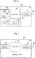
- Fig. 2 is a block diagram of the UE 100.
- the UE 100 includes plural antennas 101, a radio transceiver 110, a user interface 120, a GNSS (Global Navigation Satellite System) receiver 130, a battery 140, a memory 150, and a processor 160.
- the memory 150 corresponds to storage and the processor 160 corresponds to a controller.
- the UE 100 may not necessarily have the GNSS receiver 130.
- the memory 150 may be integrally formed with the processor 160, and this set (that is, a chip set) may be called a processor 160'.
- the antenna 101 and the radio transceiver 110 are used to transmit and receive a radio signal.
- the radio transceiver 110 converts a baseband signal (a transmission signal) output from the processor 160 into a radio signal, and transmits the radio signal from the antenna 101. Furthermore, the radio transceiver 110 converts a radio signal received by the antenna 101 into a baseband signal (a reception signal), and outputs the baseband signal to the processor 160.
- the user interface 120 is an interface with a user carrying the UE 100, and includes, for example, a display, a microphone, a speaker, and various buttons.
- the user interface 120 receives an operation from a user and outputs a signal indicating the content of the operation to the processor 160.
- the GNSS receiver 130 receives a GNSS signal in order to obtain location information indicating a geographical location of the UE 100, and outputs the received signal to the processor 160.
- the battery 140 accumulates a power to be supplied to each block of the UE 100.
- the memory 150 stores a program to be executed by the processor 160 and information to be used for processing by the processor 160.
- the processor 160 includes a baseband processor that performs modulation and demodulation, encoding and decoding and the like on the baseband signal, and a CPU (Central Processing Unit) that performs various types of processes by executing the program stored in the memory 150.
- the processor 160 may further include a codec that performs encoding and decoding on sound and video signals.
- the processor 160 executes various types of processes and various types of communication protocols described later.
- Fig. 3 is a block diagram of the eNB 200. As illustrated in Fig. 3 , the eNB 200 includes plural antennas 201, a radio transceiver 210, a network interface 220, a memory 230, and a processor 240.
- the antenna 201 and the radio transceiver 210 are used to transmit and receive a radio signal.
- the radio transceiver 210 converts a baseband signal (a transmission signal) output from the processor 240 into a radio signal, and transmits the radio signal from the antenna 201. Furthermore, the radio transceiver 210 converts a radio signal received by the antenna 201 into a baseband signal (a reception signal), and outputs the baseband signal to the processor 240.
- the network interface 220 is connected to the neighboring eNB 200 via the X2 interface and is connected to the MME/S-GW 300 via the S1 interface.
- the network interface 220 is used in communication performed on the X2 interface and communication performed on the S1 interface.
- the memory 230 stores a program to be executed by the processor 240 and information to be used for processing by the processor 240.
- the processor 240 includes a baseband processor that performs modulation and demodulation, encoding and decoding and the like on the baseband signal and a CPU that performs various types of processes by executing the program stored in the memory 230.
- the processor 240 executes various types of processes and various types of communication protocols described later.
- Fig. 4 is a protocol stack diagram of a radio interface in the LTE system. As illustrated in Fig. 4 , the radio interface protocol is classified into a first layer to a third layer of an OSI reference model, such that the first layer is a physical (PHY) layer.
- the second layer includes a MAC (Medium Access Control) layer, an RLC (Radio Link Control) layer, and a PDCP (Packet Data Convergence Protocol) layer.
- the third layer includes an RRC (Radio Resource Control) layer.
- the physical layer performs encoding and decoding, modulation and demodulation, antenna mapping and demapping, and resource mapping and demapping. Between the physical layer of the UE 100 and the physical layer of the eNB 200, user data and control signals are transmitted via a physical channel.
- the MAC layer performs priority control of data and a retransmission process by a hybrid ARQ (HARQ) and the like.
- HARQ hybrid ARQ
- the MAC layer of the eNB 200 includes a scheduler for determining a transport format (a transport block size and a modulation and coding scheme) of an uplink and a downlink, and resource blocks to be assigned to the UE 100.
- the RLC layer transmits data to an RLC layer of a reception side by using the functions of the MAC layer and the physical layer. Between the RLC layer of the UE 100 and the RLC layer of the eNB 200, user data and control signals are transmitted via a logical channel.
- the PDCP layer performs header compression and decompression, and encryption and decryption.
- the RRC layer is defined only in a control plane that handles control signals. Between the RRC layer of the UE 100 and the RRC layer of the eNB 200, a control signal (an RRC message) for various types of settings is transmitted.
- the RRC layer controls a logical channel, a transport channel, and a physical channel according to the establishment, re-establishment, and release of a radio bearer.
- an RRC connection When there is a connection (an RRC connection) between the RRC of the UE 100 and the RRC of the eNB 200, the UE 100 is in a connected state (an RRC connected state). Otherwise, the UE 100 is in an idle state (an RRC idle state).
- An NAS (Non-Access Stratum) layer positioned above the RRC layer performs session management, mobility management and the like.
- Fig. 5 is a configuration diagram of a radio frame used in the LTE system.
- OFDMA Orthogonal Frequency Division Multiple Access
- SC-FDMA Single Carrier Frequency Division Multiple Access
- a radio frame is configured by 10 subframes arranged in a time direction.
- Each subframe is configured by two slots arranged in the time direction.
- Each subframe has a length of 1 ms and each slot has a length of 0.5 ms.
- Each subframe includes plural resource blocks (RBs) in a frequency direction, and plural symbols in the time direction.
- Each resource block includes plural subcarriers in the frequency direction.
- a frequency resource can be identified by a resource block and a time resource can be identified by a subframe (or a slot).
- an interval of several symbols at the head of each subframe is a region used as a physical downlink control channel (PDCCH) for mainly transmitting a control signal. Furthermore, the remaining interval of each subframe is a region available as a physical downlink shared channel (PDSCH) for mainly transmitting user data.
- PDCH physical downlink control channel
- PDSCH physical downlink shared channel
- both ends in the frequency direction of each subframe are regions used as a physical uplink control channel (PUCCH) for mainly transmitting a control signal.
- the other portion in each subframe is a region available as a physical uplink shared channel (PUSCH) for mainly transmitting user data.
- PUSCH physical uplink shared channel
- D2D ProSe D2D proximity service
- the D2D proximity service is a service enabling direct communication without passing through a network within a synchronization cluster including plural synchronized user terminals.
- the D2D proximity service includes a discovery process (Discovery) in which a proximal terminal is discovered and a communication process (D2D communication) in which direct communication is performed.
- the D2D communication is also called Direct communication.
- a scenario in which all the UEs 100 forming the synchronization cluster are located inside a cell coverage is called “in a network coverage or In coverage (InC)".
- a scenario in which all the UEs 100 forming the synchronization cluster are located outside a cell coverage is called “out of network coverage or Out of coverage (OoC)”.
- a scenario in which some UEs 100 in the synchronization cluster are located inside a cell coverage and the remaining UEs 100 are located outside the cell coverage is called “Partial network coverage or Partial coverage”.
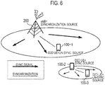
- Fig. 6 is a diagram illustrating each scenario in a network coverage and out of network coverage.
- the eNB 200 is a D2D synchronization source.
- the D2D synchronization source indicates a node from which a D2D synchronization signal (D2DSS) is transmitted.
- a D2D un-synchronization source indicates a node from which the D2D synchronization signal is not transmitted and which synchronizes to the D2D synchronization source.
- the eNB 200 which is a D2D synchronization source transmits, by a broadcast signal, D2D resource information (SA: Scheduling Assignment) indicating a radio resource available for the D2D proximity service, for example.
- the D2D resource information may be information indicating a radio resource for Discovery (hereinafter, referred to as "Discovery resource”) and a radio resource for D2D communication (hereinafter, referred to as "Communication resource").
- the UE 100-1 which is a D2D un-synchronization source performs Discovery and D2D communication on the basis of the D2D resource information received from the eNB 200.
- a predetermined UE 100 (in Fig. 6 , a UE 100-2) is a D2D synchronization source.
- the UE 100-2 which is a D2D synchronization source transmits the D2D resource information by a broadcast signal.
- a UE 100-3 which is a D2D un-synchronization source performs Discovery and D2D communication on the basis of the D2D resource information received from the UE 100-2.
- the D2D resource information is assumed to be notified by an SA reception resource pool which is an area of a previously defined radio resource. Further, in order that the UE 100 is capable of receiving the D2D resource information even in out of network coverage, the information on the SA reception resource pool is assumed to be previously configured to the UE 100.
- the UE 100 includes: a storage (memory 150) in which information on an SA reception resource pool is stored; a transmitter (processor 160 and radio transceiver 110 etc.) that transmits a synchronization signal for a D2D proximity service; and a controller (processor 160) that monitors a reception state of the synchronization signal from another UE 100 and a reception state of the control signal in the control radio resources.
- the UE 100 may receive the D2D resource information in a previously configured SA resource pool, and thus, the UE 100 needs to monitor all the previously configured SA resource pools. As shown in Fig. 7(A) , the UE 100-1 and the UE 100-2 monitor a previously configured in-network coverage SA resource pool (RX resource pool for in-coverage) and out-of-network coverage SA resource pool (RX resource pool for out-of-coverage).
- the UE 100-1 and the UE 100-2 become possible to receive the D2D resource information when the D2D resource information is designated in the SA resource pool.
- the UEs 100 need to be synchronized. As shown in Fig. 7(A) , when the UE 100-1 and the UE 100-2 are synchronized, it is possible to receive the D2D resource designated in the SA resource pool. On the other hand, as shown in Fig. 7(B) , when the UE 100-1 and the UE 100-2 are not synchronized, areas of the SA resource pool to be monitored differ, and thus, it is not possible to surely receive the D2D resource information.
- the UE 100 consumes unnecessary power resulting from the UE 100 monitoring the SA resource pool when the UE 100 is not synchronized with another UE 100, although the UE 100 is not capable of surely receiving the D2D resource information.
- the UE 100 does not monitor the SA resource pool when the UE 100 is not synchronized to another UE 100 or when the UE 100 may not be synchronized to the other UE 100.
- the UE 100 does not monitor the SA resource pool, it becomes possible to reduce the power consumption.
- the UE 100 when a UE 100 which is out of network coverage does not receive a D2D synchronization signal from another UE 100 and the UE 100 does not transmit a D2D synchronization signal, the UE 100 does not monitor an SA resource pool. As a result, it is possible to reduce power consumption. It is noted that the UE 100 regularly monitors the reception state of a synchronization signal and confirms whether there is a UE 100 that performs a D2D service in the vicinity.
- Fig. 8 illustrates an operation of the UE 100 according to the present embodiment.
- the UE 100-2 which is out of network coverage (OoC) is not receiving a D2D synchronization signal from the UE 100-1 which is in a network coverage (InC)".
- the UE 100-2 is not receiving a D2D synchronization signal from the UE 100-3 which is out of network coverage (OoC).
- the UE 100-2 is not transmitting a D2D synchronization signal.
- the UE 100-2 does not monitor the in-network coverage SA resource pool and the out-of-network coverage SA resource pool.
- the UE 100 receives a D2D synchronization signal from another UE 100 which is out of network coverage and/or the UE 100 transmits a D2D synchronization signal.
- the UE 100 monitors only the out-of-network coverage SA resource pool, among the SA resource pools.
- the UE 100 is synchronized to another UE 100 which is out of network coverage or is highly probably synchronized therewith, and thus, the UE 100 monitors the out-of-network coverage SA resource pool.
- the UE 100 is not synchronized to another UE which is in a network coverage. In this case, it is less likely that designation for D2D resources is received from the other UE 100 which is in network coverage, and thus, the UE 100 does not monitor the in-network coverage SA resource.
- D2D synchronization signal whether the other UE 100 is in a network coverage or is out of network coverage may be notified by using the D2D synchronization signal.
- a technique may be possible in which the information on "In coverage” and “Out of coverage” are included in the D2D synchronization signal.
- different formats of synchronization signal are used for "In coverage” and "Out of coverage”.
- Fig. 9 illustrates an operation of the UE 100 according to the present embodiment.
- Fig. 9 is a diagram illustrating a monitoring state of an SA resource pool when the UE 100-2 which is out of network coverage (OoC) is not receiving a D2D synchronization signal from the UE 100-1 which is in a network coverage (InC), and is synchronized to the UE 100-3 which is out of network coverage (OoC).
- OoC network coverage
- the UE 100-2 and the UE 100-3 are synchronized each other as a result of at least one of the UE 100-2 and the UE 100-3 transmitting a D2D synchronization signal.
- the UE 100-2 does not receive a D2D synchronization signal of the UE 100-1, and thus, the UE 100-2 is not synchronized to the UE 100-1.
- the UE 100-2 monitors the out-of-network coverage SA resource pool capable of receiving designation for D2D resources, as a result of synchronizing to the UE 100-3.
- the UE 100-2 is not synchronized to the UE 100-1, and it is less likely that the UE 100-2 is capable of receiving designation for D2D resources, and thus, the UE 100-2 does not monitor the in-network coverage SA resource.
- the UE 100 selects one of the other UEs.
- the UE 100 may stop transmitting the D2D synchronization signal.
- the UE 100-2 when the UE 100-2 is out of network coverage, the UE 100-2 receives a D2D synchronization signal from the UE 100-1 which is in a network coverage. In this case, the UE 100-2 monitors reception states of both the in-network coverage SA resource pool and the out-of-network coverage SA resource pool".
- the result is that the UE 100-2 and the UE 100-3 are synchronized.
- the UE 100-2 is capable of surely receiving the signal.
- the UE 100-2 monitors not only the reception state of the in-network coverage SA resource pool but also that of the out-of-network coverage SA resource pool.
- Fig. 10 illustrates an operation of the UE 100 according to the present embodiment.
- the UE 100-2 which is out of network coverage is receiving a D2D synchronization signal from the UE 100-1 which is in a network coverage.
- the UE 100-2 monitors reception states of both the in-network coverage SA resource pool and the out-of-network coverage SA resource pool. This is because there is a possibility that similarly to the UE 100-2, the UE 100-3 which is out of network coverage is receiving a D2D synchronization signal from the UE 100-1, as described above.
- the UE 100-2 which is out of network coverage receives an instruction of designating a part of the in-network coverage SA resource pool from the UE 100-1 which is in a network coverage
- the UE 100-2 monitors reception states of the notified part of the in-network coverage SA resource pool, and the out-of-network coverage SA resource pool.
- designation of the in-network coverage SA resource pool may be performed by using a D2D synchronization signal or a PD2DSCH (Physical D2D Shared Channel).
- PD2DSCH Physical D2D Shared Channel
- Fig. 11 the present operation will be described.
- the UE 100-2 which is out of network coverage receives an instruction (Indicating pool A) of monitoring a reception state of an in-network coverage SA resource pool A (RX resource pool for in-coverage A) from the UE 100-1 which is in a network coverage.
- the UE 100-2 monitors reception of the in-network coverage SA resource pool A and the out-of-network coverage SA resource pool.
- the UE 100-2 does not monitor reception of an in-network coverage SA resource pool B.
- the UE 100 when the UE 100 receives D2D synchronization signals transmitted by plural other UEs 100 which is in network coverage, the UE 100 synchronizes to a D2D synchronization signal transmitted by one UE 100 among the plural other UEs 100 which is in network coverage.
- the UE 100 may determine the other UE 100 to be synchronized, by using a signal strength of the D2D synchronization signal, a priority of the D2D synchronization signal, the size of D2D control radio resources, etc.
- the UE 100-2 which is out of network coverage is receiving a D2D synchronization signal transmitted from another UE 100-1 which is in a network coverage
- the UE 100-2 may refer to the D2D synchronization signal transmitted by the UE 100-1 to generate the D2D synchronization signal and may transmit the generated D2D synchronization signal to the UE 100-3.
- the UE 100-2 may determine on the basis of a battery remaining amount of the UE 100-2 whether to generate the synchronization signal and transmit the generated synchronization signal.
- the operation when the UE 100 monitors the reception state of the SA resource pool for D2D is described; however, these embodiments may be applied to an operation where the UE 100 discovers the other UE for D2D (D2D Discovery).
- an LTE system is described as an example of a mobile communication system, it is not limited to the LTE system, and the present invention may be applied to a system other than the LTE system.
- the present invention is useful for communication fields.
Landscapes
- Engineering & Computer Science (AREA)
- Computer Networks & Wireless Communication (AREA)
- Signal Processing (AREA)
- Databases & Information Systems (AREA)
- Mobile Radio Communication Systems (AREA)
Applications Claiming Priority (2)
| Application Number | Priority Date | Filing Date | Title |
|---|---|---|---|
| US201461990900P | 2014-05-09 | 2014-05-09 | |
| PCT/JP2015/063259 WO2015170727A1 (ja) | 2014-05-09 | 2015-05-08 | ユーザ端末及び通信制御方法 |
Publications (2)
| Publication Number | Publication Date |
|---|---|
| EP3142459A1 true EP3142459A1 (de) | 2017-03-15 |
| EP3142459A4 EP3142459A4 (de) | 2017-11-29 |
Family
ID=54392576
Family Applications (1)
| Application Number | Title | Priority Date | Filing Date |
|---|---|---|---|
| EP15789247.2A Ceased EP3142459A4 (de) | 2014-05-09 | 2015-05-08 | Benutzerendgerät und kommunikationssteuerungsverfahren |
Country Status (4)
| Country | Link |
|---|---|
| US (1) | US10098169B2 (de) |
| EP (1) | EP3142459A4 (de) |
| JP (1) | JP6130592B2 (de) |
| WO (1) | WO2015170727A1 (de) |
Cited By (1)
| Publication number | Priority date | Publication date | Assignee | Title |
|---|---|---|---|---|
| US11116021B2 (en) | 2017-03-24 | 2021-09-07 | Sony Corporation | Communication apparatus and terminal apparatus |
Families Citing this family (1)
| Publication number | Priority date | Publication date | Assignee | Title |
|---|---|---|---|---|
| JP6343672B2 (ja) * | 2013-12-20 | 2018-06-13 | 京セラ株式会社 | 装置間通信リソースの管理 |
Family Cites Families (9)
| Publication number | Priority date | Publication date | Assignee | Title |
|---|---|---|---|---|
| GB2472596A (en) * | 2009-08-11 | 2011-02-16 | Nec Corp | A system to coordinate the changing of handover/cell reselection parameters between e-utran and non e-utran rats to reduce repeated handover /cell reselection |
| JP5376333B2 (ja) * | 2010-02-24 | 2013-12-25 | 株式会社日立国際電気 | 無線通信システム |
| EP2665325B1 (de) * | 2012-05-15 | 2014-08-13 | Telefonaktiebolaget L M Ericsson (publ) | Funkverbindungsverwaltung zur netzwerkunterstützten Gerät-zu-Gerät-Kommunikation |
| WO2014051126A1 (ja) * | 2012-09-27 | 2014-04-03 | 京セラ株式会社 | 移動通信システム、ユーザ端末、プロセッサ及び基地局 |
| US11496948B2 (en) * | 2012-10-19 | 2022-11-08 | Samsung Electronics Co., Ltd. | System and method for ad-hoc/network assisted device discovery protocol for device to device communications |
| JP5421486B2 (ja) * | 2013-04-24 | 2014-02-19 | 株式会社東芝 | 無線装置および通信方法 |
| US9654960B2 (en) * | 2013-05-31 | 2017-05-16 | Qualcomm Incorporated | Server-assisted device-to-device discovery and connection |
| US11496955B2 (en) * | 2013-07-31 | 2022-11-08 | Sony Corporation | Terminal device and information processing apparatus |
| US9843989B2 (en) * | 2014-02-10 | 2017-12-12 | Nokia Solutions And Networks Oy | Uniform UE initialization procedure for both in-coverage and out-of-coverage D2D communications |
-
2015
- 2015-05-08 JP JP2016517930A patent/JP6130592B2/ja active Active
- 2015-05-08 WO PCT/JP2015/063259 patent/WO2015170727A1/ja not_active Ceased
- 2015-05-08 EP EP15789247.2A patent/EP3142459A4/de not_active Ceased
-
2016
- 2016-02-19 US US15/047,948 patent/US10098169B2/en active Active
Cited By (1)
| Publication number | Priority date | Publication date | Assignee | Title |
|---|---|---|---|---|
| US11116021B2 (en) | 2017-03-24 | 2021-09-07 | Sony Corporation | Communication apparatus and terminal apparatus |
Also Published As
| Publication number | Publication date |
|---|---|
| US20160174279A1 (en) | 2016-06-16 |
| JP6130592B2 (ja) | 2017-05-17 |
| WO2015170727A1 (ja) | 2015-11-12 |
| EP3142459A4 (de) | 2017-11-29 |
| US10098169B2 (en) | 2018-10-09 |
| JPWO2015170727A1 (ja) | 2017-04-20 |
Similar Documents
| Publication | Publication Date | Title |
|---|---|---|
| JP6295316B2 (ja) | 基地局及びプロセッサ | |
| EP3445133A1 (de) | Mobilkommunikationssystem, benutzerendgerät und basisstation | |
| US10327273B2 (en) | Receiving terminal and transmitting terminal | |
| US10021714B2 (en) | Mobile communication system and user terminal | |
| US9578614B2 (en) | User terminal and base station | |
| EP3142431A1 (de) | Kommunikationssteuerungsverfahren, benutzerendgerät und basisstation | |
| JP6174141B2 (ja) | 通信制御方法及び基地局 | |
| US9900763B2 (en) | User terminal for determining whether to transmit synchronization signal in response to a received power | |
| US10004101B2 (en) | Mobile communication system, user terminal, and processor | |
| US10098169B2 (en) | User terminal and communication control method | |
| US20160157079A1 (en) | User terminal, network apparatus, and processor | |
| JP6515083B2 (ja) | ユーザ端末及び通信制御方法 | |
| EP2981140A1 (de) | Mobilkommunikationssystem, basisstation und benutzerendgerät | |
| US20160278046A1 (en) | User terminal, base station, and processor | |
| EP3197240A1 (de) | Basisstation und benutzerendgerät | |
| EP3142396A1 (de) | Mobilkommunikationssystem, benutzerendgerät und prozessor |
Legal Events
| Date | Code | Title | Description |
|---|---|---|---|
| STAA | Information on the status of an ep patent application or granted ep patent |
Free format text: STATUS: THE INTERNATIONAL PUBLICATION HAS BEEN MADE |
|
| PUAI | Public reference made under article 153(3) epc to a published international application that has entered the european phase |
Free format text: ORIGINAL CODE: 0009012 |
|
| STAA | Information on the status of an ep patent application or granted ep patent |
Free format text: STATUS: REQUEST FOR EXAMINATION WAS MADE |
|
| 17P | Request for examination filed |
Effective date: 20161027 |
|
| AK | Designated contracting states |
Kind code of ref document: A1 Designated state(s): AL AT BE BG CH CY CZ DE DK EE ES FI FR GB GR HR HU IE IS IT LI LT LU LV MC MK MT NL NO PL PT RO RS SE SI SK SM TR |
|
| AX | Request for extension of the european patent |
Extension state: BA ME |
|
| DAV | Request for validation of the european patent (deleted) | ||
| DAX | Request for extension of the european patent (deleted) | ||
| A4 | Supplementary search report drawn up and despatched |
Effective date: 20171102 |
|
| RIC1 | Information provided on ipc code assigned before grant |
Ipc: H04W 56/00 20090101AFI20171025BHEP Ipc: H04W 92/18 20090101ALN20171025BHEP |
|
| STAA | Information on the status of an ep patent application or granted ep patent |
Free format text: STATUS: EXAMINATION IS IN PROGRESS |
|
| 17Q | First examination report despatched |
Effective date: 20181011 |
|
| REG | Reference to a national code |
Ref country code: DE Ref legal event code: R003 |
|
| STAA | Information on the status of an ep patent application or granted ep patent |
Free format text: STATUS: THE APPLICATION HAS BEEN REFUSED |
|
| 18R | Application refused |
Effective date: 20210329 |