EP3142465B1 - Farbton- und verdunkelungssteuerungsschaltungen für lampen oder led-arrays - Google Patents
Farbton- und verdunkelungssteuerungsschaltungen für lampen oder led-arrays Download PDFInfo
- Publication number
- EP3142465B1 EP3142465B1 EP16188841.7A EP16188841A EP3142465B1 EP 3142465 B1 EP3142465 B1 EP 3142465B1 EP 16188841 A EP16188841 A EP 16188841A EP 3142465 B1 EP3142465 B1 EP 3142465B1
- Authority
- EP
- European Patent Office
- Prior art keywords
- voltage
- command signal
- led
- lighting
- valley
- Prior art date
- Legal status (The legal status is an assumption and is not a legal conclusion. Google has not performed a legal analysis and makes no representation as to the accuracy of the status listed.)
- Active
Links
Images


Classifications
-
- H—ELECTRICITY
- H05—ELECTRIC TECHNIQUES NOT OTHERWISE PROVIDED FOR
- H05B—ELECTRIC HEATING; ELECTRIC LIGHT SOURCES NOT OTHERWISE PROVIDED FOR; CIRCUIT ARRANGEMENTS FOR ELECTRIC LIGHT SOURCES, IN GENERAL
- H05B45/00—Circuit arrangements for operating light-emitting diodes [LED]
- H05B45/30—Driver circuits
- H05B45/37—Converter circuits
- H05B45/3725—Switched mode power supply [SMPS]
- H05B45/38—Switched mode power supply [SMPS] using boost topology
-
- B—PERFORMING OPERATIONS; TRANSPORTING
- B64—AIRCRAFT; AVIATION; COSMONAUTICS
- B64D—EQUIPMENT FOR FITTING IN OR TO AIRCRAFT; FLIGHT SUITS; PARACHUTES; ARRANGEMENT OR MOUNTING OF POWER PLANTS OR PROPULSION TRANSMISSIONS IN AIRCRAFT
- B64D11/00—Passenger or crew accommodation; Flight-deck installations not otherwise provided for
-
- H—ELECTRICITY
- H04—ELECTRIC COMMUNICATION TECHNIQUE
- H04B—TRANSMISSION
- H04B3/00—Line transmission systems
- H04B3/54—Systems for transmission via power distribution lines
- H04B3/546—Combination of signalling, telemetering, protection
-
- H—ELECTRICITY
- H04—ELECTRIC COMMUNICATION TECHNIQUE
- H04B—TRANSMISSION
- H04B3/00—Line transmission systems
- H04B3/54—Systems for transmission via power distribution lines
- H04B3/548—Systems for transmission via power distribution lines the power on the line being DC
-
- H—ELECTRICITY
- H05—ELECTRIC TECHNIQUES NOT OTHERWISE PROVIDED FOR
- H05B—ELECTRIC HEATING; ELECTRIC LIGHT SOURCES NOT OTHERWISE PROVIDED FOR; CIRCUIT ARRANGEMENTS FOR ELECTRIC LIGHT SOURCES, IN GENERAL
- H05B45/00—Circuit arrangements for operating light-emitting diodes [LED]
- H05B45/20—Controlling the colour of the light
- H05B45/24—Controlling the colour of the light using electrical feedback from LEDs or from LED modules
-
- H—ELECTRICITY
- H05—ELECTRIC TECHNIQUES NOT OTHERWISE PROVIDED FOR
- H05B—ELECTRIC HEATING; ELECTRIC LIGHT SOURCES NOT OTHERWISE PROVIDED FOR; CIRCUIT ARRANGEMENTS FOR ELECTRIC LIGHT SOURCES, IN GENERAL
- H05B45/00—Circuit arrangements for operating light-emitting diodes [LED]
- H05B45/30—Driver circuits
- H05B45/37—Converter circuits
- H05B45/3725—Switched mode power supply [SMPS]
- H05B45/375—Switched mode power supply [SMPS] using buck topology
-
- B—PERFORMING OPERATIONS; TRANSPORTING
- B64—AIRCRAFT; AVIATION; COSMONAUTICS
- B64D—EQUIPMENT FOR FITTING IN OR TO AIRCRAFT; FLIGHT SUITS; PARACHUTES; ARRANGEMENT OR MOUNTING OF POWER PLANTS OR PROPULSION TRANSMISSIONS IN AIRCRAFT
- B64D11/00—Passenger or crew accommodation; Flight-deck installations not otherwise provided for
- B64D2011/0053—Cabin passenger reading lights
-
- H—ELECTRICITY
- H04—ELECTRIC COMMUNICATION TECHNIQUE
- H04B—TRANSMISSION
- H04B2203/00—Indexing scheme relating to line transmission systems
- H04B2203/54—Aspects of powerline communications not already covered by H04B3/54 and its subgroups
- H04B2203/5404—Methods of transmitting or receiving signals via power distribution lines
- H04B2203/5412—Methods of transmitting or receiving signals via power distribution lines by modofying wave form of the power source
-
- H—ELECTRICITY
- H04—ELECTRIC COMMUNICATION TECHNIQUE
- H04B—TRANSMISSION
- H04B2203/00—Indexing scheme relating to line transmission systems
- H04B2203/54—Aspects of powerline communications not already covered by H04B3/54 and its subgroups
- H04B2203/5404—Methods of transmitting or receiving signals via power distribution lines
- H04B2203/5416—Methods of transmitting or receiving signals via power distribution lines by adding signals to the wave form of the power source
-
- H—ELECTRICITY
- H04—ELECTRIC COMMUNICATION TECHNIQUE
- H04B—TRANSMISSION
- H04B2203/00—Indexing scheme relating to line transmission systems
- H04B2203/54—Aspects of powerline communications not already covered by H04B3/54 and its subgroups
- H04B2203/5429—Applications for powerline communications
- H04B2203/5458—Monitor sensor; Alarm systems
-
- H—ELECTRICITY
- H04—ELECTRIC COMMUNICATION TECHNIQUE
- H04B—TRANSMISSION
- H04B2203/00—Indexing scheme relating to line transmission systems
- H04B2203/54—Aspects of powerline communications not already covered by H04B3/54 and its subgroups
- H04B2203/5462—Systems for power line communications
- H04B2203/547—Systems for power line communications via DC power distribution
-
- H—ELECTRICITY
- H05—ELECTRIC TECHNIQUES NOT OTHERWISE PROVIDED FOR
- H05B—ELECTRIC HEATING; ELECTRIC LIGHT SOURCES NOT OTHERWISE PROVIDED FOR; CIRCUIT ARRANGEMENTS FOR ELECTRIC LIGHT SOURCES, IN GENERAL
- H05B47/00—Circuit arrangements for operating light sources in general, i.e. where the type of light source is not relevant
- H05B47/10—Controlling the light source
- H05B47/175—Controlling the light source by remote control
- H05B47/196—Controlling the light source by remote control characterised by user interface arrangements
-
- Y—GENERAL TAGGING OF NEW TECHNOLOGICAL DEVELOPMENTS; GENERAL TAGGING OF CROSS-SECTIONAL TECHNOLOGIES SPANNING OVER SEVERAL SECTIONS OF THE IPC; TECHNICAL SUBJECTS COVERED BY FORMER USPC CROSS-REFERENCE ART COLLECTIONS [XRACs] AND DIGESTS
- Y02—TECHNOLOGIES OR APPLICATIONS FOR MITIGATION OR ADAPTATION AGAINST CLIMATE CHANGE
- Y02B—CLIMATE CHANGE MITIGATION TECHNOLOGIES RELATED TO BUILDINGS, e.g. HOUSING, HOUSE APPLIANCES OR RELATED END-USER APPLICATIONS
- Y02B20/00—Energy efficient lighting technologies, e.g. halogen lamps or gas discharge lamps
- Y02B20/30—Semiconductor lamps, e.g. solid state lamps [SSL] light emitting diodes [LED] or organic LED [OLED]
Definitions
- Aircraft lighting systems are used to provide lighting for various purposes. Some systems provide illumination of instrumentation. Some systems illuminate cabin spaces. Some systems are for external lighting. Some systems provide overhead illumination of passenger seating areas to facilitate reading. Light Emitting Diode (LED) arrays are used to provide illumination for some of these lighting systems. LED arrays can require large power controllers to control the hue and brightness. Such power controllers can be located near each individual lighting source, resulting in a large number of such controllers. Having controllers distributed throughout an aircraft can contribute weight to the aircraft and add expense to the cost of the aircraft.
- LED Light Emitting Diode
- the intensity of light emission from LED lighting arrays changes in response to an applied power to the LED lighting array. As the applied power is increased, the intensity of light emission usually increases. Some LED lighting arrays emit a light whose color is also a function of the power consumed by the LED lighting array. For example, the color of the emitted light can change in response to a change in the applied voltage to the LED lighting array. People expect that some lighting systems will have a specific color. For example, when reading, people expect overhead illumination to be within a predetermined range of colors called "white light.”
- both intensity and hue are functions of the voltage and current applied to an LED lighting array
- control of both intensity and hue are performed using pulsed methods.
- the voltage and current levels are determined by a color specification.
- a duty cycle is determined by an intensity specification.
- the frequency rate at which these pulses are applied to an LED lighting array is bounded by two different concerns or hazards. If the pulse rate is too low, a human will perceive the LED lighting array to be undesirably flickering. If the pulse rate is too high, conducted and/or radiated emissions may cause undesirable coupling to sensitive airplane instrumentation.
- CN 102 548 101 teaches using multiple, differently coloured LEDs for generating colour control.
- US 2015/237700 discloses a system and method for controlling the brightness and colour of LED lighting.
- Apparatus and associated methods relate to a lighting system for emitting light of a controlled hue and of a controlled intensity. According to a first aspect, a lighting system according to claim 1 is provided.
- the lighting power control system includes a DC power supply that generates a supply signal.
- the lighting power control system includes a chopper that chops the supply signal.
- the lighting power control system includes a filter that filters the chopped supply signal.
- the lighting power control system also includes a processor that controls the DC power supply and the chopper.
- the DC power supply is controlled such that the filtered chopped supply signal has a peak that corresponds to a hue of a Light Emitting Diode (LED).
- the chopper is controlled such that the filtered chopped supply signal has a ratio of a valley of the filtered chopped supply signal to the peak of the filtered chopped supply signal. The ratio corresponds to a duty cycle that, when applied to the LED, will result in emission of light corresponding to a predetermined intensity value.
- This specification discloses an exemplary method of providing hue and intensity control locally with respect to a lighting element in response to a control signal generated remotely at a lighting power controller.
- FIG. 1 is a block diagram of an exemplary system for controlling hue and dimming of Light Emitting Diodes (LEDs).
- exemplary lighting control system 100 includes lighting power control system 102, lighting element controller 104, and LED 106.
- Lighting power control system 102 includes microprocessor 108, DC power supply 110, AC modulator 112, and Filter 114.
- Lighting element controller 104 includes Input/Output buffer 118, peak detector 120, valley detector 122, amplitude controller 124, duty cycle controller 126 and power switch 128.
- Lighting power control system 102 sends command signal 130 to lighting element controller 104 via circuit net 132.
- Lighting element controller 104 sends excitation signal 134 to LED 106 via circuit net 136.
- LED 106 can represent a single LED or an array of LEDS all excited by excitation signal 134 carried on circuit net 136 or by a copy of excitation signal 134 carried on one or more other circuit nets.
- Lighting element controller 104 receives control signal 130 and converts control signal 130 to excitation signal 134 which will be used to affect a hue and an intensity of light from LED 106.
- the hue and intensity commands are encoded in the control signal 130 using voltage peak, V peak 138, and voltage valley, V valley 140, of control signal 130.
- V peak 138 and V valley 140 are maximum and minimum voltages, respectively, of command signal 130, which has a DC level and an AC modulation.
- V peak 138 which is measured with respect to ground reference voltage 142, specifies a peak voltage amplitude of excitation signal 134.
- a ratio of V valley 140 to V peak 138 specifies the duty cycle of the excitation signal 134.
- the duty cycle of excitation signal 134 can be expressed as the pulse width, t pw 144, divided by the period, t period 146.
- Lighting power control system 102 creates control signal 130 by way of microprocessor operations in the exemplary embodiment depicted.
- Microprocessor 108 may receive inputs from a user interface (not depicted), for example, that include desired hue and intensity information of LED 106.
- microprocessor 108 provides DC power supply 110 with command signals that causes DC power supply 110 to create a DC signal having the commanded DC level.
- DC power supply 110 then provides AC modulator 112 the commanded DC signal.
- microprocessor 108 provides AC modulator 112 with a command signal that causes AC modulator 112 to modulate the received DC signal with the commanded AC modulation.
- AC modulator 112 then provides the AC modulated signal to filter 114.
- microprocessor 108 provides filter 114 with a command signal that causes filter 114 to apply a commanded filtering operation to the received AC modulated signal.
- filter 114 may be static and may receive no command signal from microprocessor 108.
- Filter 114 provides command signal 130 to circuit net 132 as an output of lighting power control system 102. Filter 114 also provides command signal 130 to microprocessor 108.
- Lighting element controller 104 transforms command signal 130 into excitation signal 134.
- Input/Output block 118 of Lighting element controller 104 receives command signal 130 from circuit net 132.
- Input/Output block 118 might provide electro-magnetic interference filtering of command signal 130.
- Input/Output block 118 provides the received command signal to both peak detector 120 and valley detector 122.
- Peak detector 120 detects a maximum voltage of the received signal, and provides a signal containing information representing the detected maximum voltage both to amplitude controller 124 and to duty cycle controller 126.
- Valley detector 122 detects a minimum voltage of the received signal, and provides a signal containing information representing the detected minimum voltage to duty cycle controller 126.
- Amplitude controller 124 and duty cycle controller 126 provide signals used by power switch 128 for generating excitation signal 134.
- amplitude controller 124 may simply transmit V peak 138 to power switch 128.
- Power switch 128 generates excitation signal 134 having V peak 138 and a duty cycle substantially equal to a ratio of pulse width 144 to period 146.
- Lighting system 100 may be used to control lighting elements in an aircraft.
- An aircraft may have many LEDs 106 located in various locations about an aircraft.
- LEDs 106 may be grouped into a number of independently controllable groups.
- Each independently controllable group might have a dedicated lighting element controller 104 which provides excitation signal 134 to its associated group of LEDs 106.
- Each independent lighting element 104 controller may be located proximate the group of LEDs 106 of which it controls. By performing the conversion of user inputs into command signals 130 at a remote location, independent lighting element controllers 104 need not perform such functions. Dividing functionality in such a way can reduce the cost, weight, and/or complexity of independent lighting element controllers 104.
- Lighting power control system 102 may be located at a convenient location of an aircraft. Each lighting element controller 104 may receive an independent command signal 130 from lighting power control system 102. Each command signal contains both an intensity command and a hue command that can be carried on a single pair of wires or with one power wire and using the aircraft grounding system as the return in place of a second wire. Such a configuration can advantageously reduce the cost and/or weight of a wiring harness.
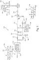
- FIG. 2 is schematic diagram of an exemplary lighting power control system.
- exemplary lighting power control system 102 includes microprocessor 108, power monitoring resistor 148, input filter 150, capacitor 152, step-down transistor 154, diode 156, inductor 158, step-up transistor 160, diode 162, capacitor 164, and output filter 166.
- Microprocessor 108 communicates with systems, such as, for example, a user interface or a control system, via communications signals carried on circuit net 168.
- Microprocessor 108 monitors input current from a power supply such as a 28 volt power feed on circuit net 170, by monitoring a voltage drop across power monitoring resistor 148.
- Filter 150 removes undesirable noise from the 28 volt power feed and prevents locally generated noise from escaping onto the 28V feed.
- Capacitor 152 provides a source of charge storage for lighting power control system 102.
- Lighting power control system 102 can operate as a buck converter by switching step-down transistor 154. Lighting power control system 102 can also operate as a boost converter by switching step-up transistor 160. Some embodiments may include only capability to operate as either a buck converter or a boost converter. In such embodiments, either step-up transistor 160 used for boost conversion or step-down transistor 154 used for buck conversion may be eliminated.
- Step-down transistor 154 is controlled by microprocessor 108 to provide a pulse-width modulated conductance of charge from capacitor 152 to circuit net 172.
- Inductor 158 conducts the charge from circuit net 172 to circuit net 174.
- Diode 156 prevents circuit net 172 from having a significant negative voltage when step-down transistor 154 is turned off, as current cannot instantaneously turn off in inductor 158.
- Step-up transistor 160 modulates the signal carried on circuit net 174. In normal operation step-down transistor 154 and step-up transistor 160 are not operated simultaneously.
- Transistor 168 is controlled by microprocessor 108.
- Diode 162 provides conduction of the modulated signal from circuit net 174 to filter 166.
- Capacitor 164 and filter 166 condition the modulated signal, and filter 166 provides command signal 130 to circuit net 132.
- microprocessor 108 monitors command signal 130 and performs closed loop feedback operations to ensure that command signal 130 has predetermined V peak 138 and predetermined V valley 140.
- a second current monitoring function can be added between output filter 166 and circuit net 132 to facilitate closed-loop control of current.
- FIG. 3 is a schematic diagram of an exemplary lighting element controller.
- exemplary lighting element controller 104 includes lightning protection filter 176, peak detector 120 including diode 178 and capacitor 180, valley detector 122, which includes diode 182 and capacitor 184, resistor 186, triangle generator 188, comparator 190 and transistor 192.
- Command signal 130 is received by lighting element controller 104 via input circuit net 132.
- lightning protection filter 176 provides filtering and/or signal protection or both for received command signal 130.
- snubbers might provide circuit protection of lighting element controller 104.
- a low-pass filter can remove unwanted high-frequency noise that could have coupled to circuit net 132 and/or can block locally generated noise by transistor 192 from coupling to circuit net 132.
- Resistor 186 provides a leakage path between V peak 138 on circuit net 194 and V valley 140 on circuit net 196.
- Triangle generator 188 provides sawtooth triangle signal 198 between a reference voltage and V peak 138 carried on circuit net 194. If sawtooth triangle signal 198 is less than V valley 140, then comparator 190 will drive transistor 192 to an on state in which transistor 192 provides V peak 138 on circuit net 194 to output circuit net 136. If sawtooth triangle signal 198 is greater than V valley 140, then comparator 190 will turn off drive transistor 192. When drive transistor 192 is turned off, LED 106, which is connected to circuit net 136, will pull circuit net 136 to the reference voltage (typically a "ground" potential).
- a ratio of V valley 140 to V peak 138 specifies the duty cycle of a high-voltage portion of the excitation signal 134.
- the polarity of the comparator can be inverted.
- a ratio of V valley 140 to V peak 138 specifies the duty cycle of a low-voltage portion of excitation signal 134.
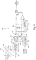
- FIG. 4 is a schematic diagram of an exemplary lighting element controller with dual direction or 'full duplex' communication capability.
- exemplary lighting element controller can communicate information to lighting power control system 102 via circuit net 132.
- FIG. 4 's exemplary lighting element controller 104' includes every circuit element of exemplary lighting element controller 104 depicted in FIG. 3 , plus some additional circuit components.
- a resonant tank circuit 202 Between lightning protection filter 176 and peak and valley detectors 178, 180, 182, 184 are a resonant tank circuit 202, capacitor 206, and controlled resistance 208.
- Resonant tank circuit includes capacitor 203 and inductor 204. Controlled resistance 208 can cause lighting element controller 104' to deliver more AC current through circuit net 132.
- Lighting power control system 102 can then monitor the AC current content being provided and interpret the provided current into signal information.
- controlled resistance 208 is essentially a DC signal or only a signal that changes very slowly (e.g., a low-frequency signal). Controlled resistance 208 may provide a controlled load to the modulation that is present on signal 130 while resonant tank circuit 202 blocks the modulation. Controlled resistance 208 is coupled to line 132 through capacitor 206 and lightning protection filter 176. The value of controlled resistance 208 may permit a current proportional to the modulation voltage and inversely proportional to the resistance to flow which can then be detected by microprocessor 108, which interprets the detected current as information that represents the value of the controlled resistance.
- controlled resistance 208 can be modulated at frequencies are substantially blocked by resonant tank circuit 202.
- Resonant tank circuit 202 can provide good transmission of the average value of command signal 130 while simultaneously rejecting frequencies associated with modulating controlled resistance 208.
- various frequencies can be used to supply the AC modulation of a command signal.
- a fundamental frequency of modulation might be between 100 Hz and 5 kHz.
- the fundamental frequency of modulation might be between 1 kHz and 3 kHz, for example.
- the command signal provides operating power for the lighting element controller.
- the command signal provides operating power for the LED controlled by the lighting element controller to which the command signal is provided.
- FIG. 5 is a flow chart of an exemplary method of controlling both a hue and an intensity of a LED.
- exemplary method 300 is executed in part by lighting power control system 305 and in part by lighting element controller 310.
- Method 300 begins with lighting power control system 305 creating a command signal at step 315.
- lighting power control system 305 sends the created command signal to lighting element controller 310.
- lighting element controller 310 receives the command signal.
- lighting element controller 310 detects a peak voltage of the received command signal.
- lighting element controller 310 detects a valley voltage of the received command signal.
- lighting element controller 310 generates a pulse stream based on the detected peak voltage and the detected valley voltage.
- lighting element controller 310 sends the generated pulse stream to LED 350.
- lighting element controller 310 generates a load condition.
- lighting element controller 310 sends the generated load condition to lighting power control system 305.
- lighting power control system 305 receives the load condition.
- lighting power control system 305 interprets the load condition. For example, a load condition within predetermined limits may be indicative of a failure (e.g., a LED that doesn't illuminate).
- a lighting system for emitting light of a controlled hue and of a controlled intensity includes a light-emitting diode (LED) that emits light having a hue that varies in response to variations in a voltage applied to the LED, the emitted light having an intensity that varies in response to variations in a duty-cycle of the voltage applied to the LED.
- the lighting system also includes a controller configured to receive a command signal having both AC and DC components that result in the command signal having a periodic peak voltage and a periodic valley voltage, the peak voltage being indicative of the controlled hue, and a ratio of the valley voltage to the peak voltage indicative of the controlled intensity.
- the controller includes a peak detector that detects the peak voltage and a valley detector that detects the valley voltage.
- the controller also includes a pulse generator that generates a pulse stream having a pulse-voltage magnitude substantially equal to the detected peak voltage and a pulse-voltage duty cycle substantially equal to the ratio of the detected valley voltage to the detected peak voltage.
- the generated pulse stream is applied to the LED resulting in light emission of the controlled hue and of the controlled intensity.
- the pulse generator can include a triangle wave generator
- the triangle wave generator can generate a sawtooth triangle wave between a reference voltage and the peak voltage.
- the pulse generator can include a comparator
- the comparator can be configured to generate a signal that is in a first state when the sawtooth triangle wave is greater than the valley voltage and is in a second state when the sawtooth triangle wave is less than the valley voltage.
- the AC component of the command signal can include a first frequency range
- the controller further can include a status reporting module, and wherein the status reporting module can modulate the command signal in a second frequency range, the second frequency range non-overlapping the first frequency range.
- AC component of the command signal can have a fundamental frequency between 1 kHz and 3 kHz.
- any of the foregoing lighting systems can optionally include, additionally and/or alternatively, any one or more of the following features, configurations and/or additional components: i) a switch that connects the LED to the peak voltage when the generated signal is in the first state, and disconnects the LED from the peak voltage when the generated signal is in the second state; and/or ii) a lighting power controller for generating a plurality of lighting control signals.
- the lighting power controller can include any one or more of the following features, configurations and/or additional components: a) a DC power supply that generates a supply signal; b) a chopper that chops the supply signal; c) a filter that filters the chopped supply signal; and/or d) a processor that controls the DC power supply and the chopper, the DC power supply being controlled such that the filtered chopped supply signal has a peak that corresponds to the hue of the LED, the chopper being controlled such that the filtered chopped supply signal has a ratio of a valley of the filtered chopped supply signal to the peak of the filtered chopped supply signal, the ratio corresponding to a duty cycle that, when applied to the LED, will result in emission of light corresponding to a predetermined intensity value.
- a method of controlling both a hue and an intensity of a Light Emitting Diode (LED) includes creating, in a lighting power control system, a command signal having both AC and DC components that give the command signal a peak voltage and a valley voltage, the peak voltage being indicative of the predetermined color value, a ratio of the valley voltage to the peak voltage being indicative of the predetermined intensity value.
- the method includes sending the command signal from the lighting power control system to a lighting element controller.
- the method includes detecting, in the lighting element controller, the peak voltage of the command signal.
- the method includes detecting, in the lighting element controller, the valley voltage of the command signal.
- the method includes generating, in the lighting element controller, a pulse stream that has a pulse-voltage magnitude substantially equal to the detected peak voltage and a pulse-voltage duty cycle substantially equal to the ratio of the detected valley voltage to the detected peak voltage.
- the method includes providing the generated pulse stream to the LED.
- a further embodiment of the foregoing method, wherein generating the pulse stream can include generating a sawtooth triangle wave between a reference voltage and the peak voltage.
- generating the pulse stream can include comparing the sawtooth triangle wave to the detected valley voltage, and wherein if the sawtooth triangle wave is greater than the detected valley voltage a first voltage is provided to the LED, and when the sawtooth triangle wave is less than the valley voltage a second voltage is provided to the LED.
- AC component of the command signal can have a fundamental frequency between 100 Hz and 5 kHz.
- AC component of the command signal can have a fundamental frequency between 1 kHz and 3 kHz.
- a lighting power control system for generating a lighting control signal includes a DC power supply that generates a supply signal, a chopper that chops the supply signal, a filter that filters the chopped supply signal, and a processor that controls the DC power supply and the chopper.
- the DC power supply is controlled such that the filtered chopped supply signal has a peak voltage that corresponds to a hue of a Light Emitting Diode (LED).
- LED Light Emitting Diode
- the chopper is controlled such that the filtered chopped supply signal has a ratio of a valley voltage of the filtered chopped supply signal to the peak voltage of the filtered chopped supply signal, the ratio corresponding to a duty cycle that, when applied to the LED, will result in emission of light corresponding to a predetermined intensity value.
- a further embodiment of the foregoing lighting power control system wherein the processor can monitor the filtered chopped supply signal so as to ensure that the peak voltage is substantially equal to a predetermined peak threshold.
- a further embodiment of any of the foregoing lighting power control systems wherein the processor can monitor the filtered chopped supply signal so as to ensure that the valley voltage is substantially equal to a predetermined valley threshold.
- a further embodiment of any of the foregoing lighting power control systems, wherein filtered chopped supply signal can have a fundamental frequency between 100 Hz and 5 kHz.
- any of the foregoing lighting power control systems can optionally include, additionally and/or alternatively, a load sensor that can sense the current drawn by a load to which the lighting power control system provides the filtered chopped supply signal, the sensed current being indicative of information communicated by the load to the lighting power control system.
Landscapes
- Engineering & Computer Science (AREA)
- Power Engineering (AREA)
- Computer Networks & Wireless Communication (AREA)
- Signal Processing (AREA)
- Aviation & Aerospace Engineering (AREA)
- Circuit Arrangement For Electric Light Sources In General (AREA)
Claims (15)
- Beleuchtungssystem (100) zum Emittieren von Licht mit einem gesteuertem Farbton und einer gesteuerten Intensität, wobei das Beleuchtungssystem (100) Folgendes umfasst:eine Leuchtdiode, LED, (106), die dazu konfiguriert ist, Licht mit einem Farbton zu emittieren, der als Reaktion auf Schwankungen einer Spannung, die an die LED (106) angelegt wird, variiert, wobei das emittierte Licht eine Intensität aufweist, die als Reaktion auf Schwankungen in einem Betriebszyklus der Spannung, die an die LED (106) angelegt wird, variiert; undeine Steuerung (104), die dazu konfiguriert ist, ein Steuersignal (130) zu empfangen, sowohl Wechselstrom- als auch Gleichstromkomponenten aufweisend, die dazu führen, dass das Steuersignal (130) eine periodische Spitzenspannung (138) und eine periodische Talspannung (140) aufweist, wobei die Spitzenspannung (138) den gesteuerten Farbton anzeigt und ein Verhältnis der Talspannung (140) zu der Spitzenspannung (138) die gesteuerte Intensität anzeigt, wobei die Steuerung (104) Folgendes umfasst:einen Spitzendetektor (120), der dazu konfiguriert ist, die Spitzenspannung (138) zu erfassen;einen Taldetektor (122), der dazu konfiguriert ist, die Talspannung (140) zu erfassen;und dadurch gekennzeichnet, dass die Steuerung ferner Folgendes umfasst:einen Impulsgenerator, der einen Impulsstrom generiert, der eine Impulsspannungsgröße im Wesentlichen gleich der erfassten Spitzenspannung (138) und einen Impulsspannungs-Betriebszyklus im Wesentlichen gleich dem Verhältnis von der erfassten Talspannung (140) zu der erfassten Spitzenspannung (138) aufweist,wobei der generierte Impulsstrom an die LED (106) angelegt wird, was eine Lichtemission des gesteuerten Farbtons und der gesteuerten Intensität zur Folge hat.
- Beleuchtungssystem (100) nach Anspruch 1, wobei der Impulsgenerator einen Dreieckwellengenerator (188) umfasst, wobei der Dreieckwellengenerator (188) dazu konfiguriert ist, eine Sägezahn-Dreieckwelle (198) zwischen einer Referenzspannung und der Spitzenspannung (138) zu generieren.
- Beleuchtungssystem (100) nach Anspruch 2, wobei der Impulsgenerator einen Komparator (190) umfasst, wobei der Komparator (190) dazu konfiguriert ist, ein Signal zu generieren, das sich in einem ersten Zustand befindet, wenn die Sägezahn-Dreieckwelle (198) größer ist als die Talspannung (140), und sich in einem zweiten Zustand befindet, wenn die Sägezahn-Dreieckwelle (198) kleiner ist als die Talspannung (140) .
- Beleuchtungssystem (100) nach Anspruch 3, ferner umfassend einen Schalter, wobei der Schalter dazu konfiguriert ist, die LED (106) mit der Spitzenspannung (138) zu verbinden, wenn sich das generierte Signal in dem zweiten Zustand befindet, und dazu konfiguriert ist, die LED (106) von der Spitzenspannung (138) zu trennen, wenn sich das generierte Signal in dem ersten Zustand befindet.
- Beleuchtungssystem (100) nach einem der vorstehenden Ansprüche, wobei die Wechselstromkomponente des Steuersignals (130) einen ersten Frequenzbereich umfasst, wobei die Steuerung (104) ferner ein Statusberichtmodul umfasst, und wobei das Statusberichtmodul dazu konfiguriert ist, das Steuersignal (130) in einem zweiten Frequenzbereich zu modulieren, wobei der zweite Frequenzbereich nicht mit dem ersten Frequenzbereich überlappt.
- Beleuchtungssystem (100) nach einem der Ansprüche 1 bis 4, wobei die Wechselstromkomponente des Steuersignals (130) eine Grundfrequenz zwischen 100 Hz und 5 kHz aufweist.
- Beleuchtungssystem (100) nach einem der Ansprüche 1 bis 4, wobei die Wechselstromkomponente des Steuersignals (130) eine Grundfrequenz zwischen 1 kHz und 3 kHz aufweist.
- Beleuchtungssystem (100) nach einem der vorstehenden Ansprüche, ferner umfassend eine Beleuchtungs-Leistungssteuerung zum Generieren des Steuersignals (130), wobei die Beleuchtungs-Leistungssteuerung Folgendes umfasst:eine Gleichstrom-Leistungszufuhr (110), die dazu konfiguriert ist, ein Zufuhrsignal zu generieren;einen Wechselstrom-Modulator (112), der dazu konfiguriert ist, das Zufuhrsignal zu modulieren;einen Filter (114), der dazu konfiguriert ist, das wechselstrommodulierte Zufuhrsignal zu filtern, wodurch das Steuersignal (130) generiert wird; und gekennzeichnet durcheinen Prozessor (108), der dazu konfiguriert ist, die Gleichstrom-Leistungszufuhr und den Wechselstrom-Modulator zu steuern, wodurch die Gleichstrom-Leistungszufuhr derart gesteuert wird, dass das Steuersignal eine Spitze aufweist, die, wenn an die LED angelegt, eine Lichtemission zur Folge hat, die dem Farbton der LED entspricht, wobei der Wechselstrom-Modulator derart gesteuert ist, dass das Steuersignal ein Verhältnis zwischen einem Tal des Steuersignals und der Spitze des Steuersignals aufweist, wobei das Verhältnis einem Betriebszyklus entspricht, der, wenn an die LED angelegt, eine Lichtemission zur Folge hat, die einem vorbestimmten Intensitätswert entspricht.
- Beleuchtungssystem (100) nach einem der vorstehenden Ansprüche, wobei die Betriebsleistung für die Steuerung und für die LED (106) durch das Steuersignal (130) bereitgestellt wird.
- Verfahren zum Steuern sowohl eines Farbtons als auch einer Intensität einer Leuchtdiode, LED, (106), wobei das Verfahren Folgendes umfasst:Empfangen, durch eine Beleuchtungselementsteuerung (104), eines Steuersignals (130), sowohl Wechselstrom- als auch Gleichstromkomponenten aufweisend, die dem Steuersignal (130) eine Spitzenspannung (138) und eine Talspannung (140) geben, wobei die Spitzenspannung (138) den vorbestimmten Farbwert anzeigt, wobei ein Verhältnis von der Talspannung (140) zur Spitzenspannung (138) den vorbestimmten Intensitätswert anzeigt;Erfassen, in der Beleuchtungselementsteuerung (104), der Spitzenspannung (138) des Steuersignals (130);Erfassen, in der Beleuchtungselementsteuerung (104), der Talspannung (140) des Steuersignals (130); gekennzeichnet durchGenerieren, in der Beleuchtungselementsteuerung (104), eines Impulsstroms, der eine Impulsspannungsgröße im Wesentlichen gleich der erfassten Spitzenspannung (138) und einen Impulsspannungs-Betriebszyklus im Wesentlichen gleich dem Verhältnis der erfassten Talspannung (140) zu der erfassten Spitzenspannung (138) aufweist; undBereitstellen des generierten Impulsstroms an die LED (106) .
- Verfahren nach Anspruch 10, wobei das Generieren des Impulsstroms Generieren einer Sägezahn-Dreieckwelle (198) zwischen einer Referenzspannung und der Spitzenspannung (138) umfasst.
- Verfahren nach Anspruch 11, wobei das Generieren des Impulsstroms Vergleichen der Sägezahn-Dreieckwelle (198) mit der erfassten Talspannung (140) umfasst, und wobei, wenn die Sägezahn-Dreieckwelle (198) größer als die erfasste Talspannung (140) ist, der LED (106) eine erste Spannung bereitgestellt wird, und, wenn die Sägezahn-Dreieckwelle (198) kleiner als die Talspannung (140) ist, der LED (106) eine zweite Spannung bereitgestellt wird.
- Verfahren nach Anspruch 10, 11 oder 12, ferner umfassend Erfassen, in dem Beleuchtungsleistungssteuerungssystem (102), eines Lastzustands der Beleuchtungselementsteuerung (104), wobei der Lastzustand Informationen anzeigt, die von der Beleuchtungselementsteuerung (104) an das Beleuchtungsleistungssteuerungssystem (102) kommuniziert werden.
- Verfahren nach einem der Ansprüche 10 bis 13, wobei die Wechselstromkomponente des Steuersignals eine Grundfrequenz zwischen 100 Hz und 5 kHz aufweist.
- Verfahren nach Anspruch 14, wobei die Wechselstromkomponente des Steuersignals eine Grundfrequenz zwischen 1 kHz und 3 kHz aufweist.
Applications Claiming Priority (1)
| Application Number | Priority Date | Filing Date | Title |
|---|---|---|---|
| US14/853,633 US9572219B1 (en) | 2015-09-14 | 2015-09-14 | Hue and dimming control circuits for lamps or LED arrays |
Publications (3)
| Publication Number | Publication Date |
|---|---|
| EP3142465A2 EP3142465A2 (de) | 2017-03-15 |
| EP3142465A3 EP3142465A3 (de) | 2017-05-03 |
| EP3142465B1 true EP3142465B1 (de) | 2019-11-06 |
Family
ID=56926131
Family Applications (1)
| Application Number | Title | Priority Date | Filing Date |
|---|---|---|---|
| EP16188841.7A Active EP3142465B1 (de) | 2015-09-14 | 2016-09-14 | Farbton- und verdunkelungssteuerungsschaltungen für lampen oder led-arrays |
Country Status (2)
| Country | Link |
|---|---|
| US (1) | US9572219B1 (de) |
| EP (1) | EP3142465B1 (de) |
Families Citing this family (5)
| Publication number | Priority date | Publication date | Assignee | Title |
|---|---|---|---|---|
| US9893634B2 (en) * | 2016-05-06 | 2018-02-13 | Semiconductor Components Industries, Llc | Hybrid control technique for power converters |
| WO2019148163A1 (en) * | 2018-01-29 | 2019-08-01 | Once Innovations, Inc. | Dimmer |
| CN110708092B (zh) * | 2019-08-28 | 2022-04-22 | 绍兴凯晟照明电器有限公司 | 通过斩波实现电力线通讯的方法 |
| EP3876676A1 (de) * | 2020-03-03 | 2021-09-08 | Signify Holding B.V. | Treiber zum antrieb einer last sowie eine entsprechende led-basierte beleuchtungsvorrichtung und entsprechendes verfahren zum betrieb des treibers |
| CN115580955A (zh) * | 2022-10-08 | 2023-01-06 | 广东夏野日用电器有限公司 | 一种促进视焦调节的照明系统 |
Citations (2)
| Publication number | Priority date | Publication date | Assignee | Title |
|---|---|---|---|---|
| DE202012100843U1 (de) * | 2011-03-17 | 2012-04-02 | Insta Elektro Gmbh | Steuergerät zum Ansteuern einer zumindest ein aktives Leuchtmittel umfassenden Lampeneinheit sowie Lampeneinheit dafür |
| US20150237700A1 (en) * | 2011-07-26 | 2015-08-20 | Hunter Industries, Inc. | Systems and methods to control color and brightness of lighting devices |
Family Cites Families (13)
| Publication number | Priority date | Publication date | Assignee | Title |
|---|---|---|---|---|
| US8100552B2 (en) | 2002-07-12 | 2012-01-24 | Yechezkal Evan Spero | Multiple light-source illuminating system |
| TWI248598B (en) * | 2002-12-31 | 2006-02-01 | Hon Hai Prec Ind Co Ltd | Driving apparatus of LED |
| US7333011B2 (en) | 2004-07-06 | 2008-02-19 | Honeywell International Inc. | LED-based luminaire utilizing optical feedback color and intensity control scheme |
| US7675248B2 (en) | 2007-06-01 | 2010-03-09 | Honeywell International Inc. | Dual mode searchlight dimming controller systems and methods |
| US8716952B2 (en) | 2009-08-04 | 2014-05-06 | Cree, Inc. | Lighting device having first, second and third groups of solid state light emitters, and lighting arrangement |
| EP2506685A4 (de) * | 2010-12-02 | 2013-10-16 | Sunsun Lighting China Co Ltd | Led-antriebsstromzufuhrschaltkreis, antriebsstromzufuhr und beleuchtungsvorrichtung damit |
| CN102548101B (zh) * | 2010-12-27 | 2014-05-28 | 英飞特电子(杭州)股份有限公司 | 一种led调光系统 |
| US8531112B2 (en) * | 2011-05-15 | 2013-09-10 | Green Solution Technology Co., Ltd | LED driving circuit and protecting circuit thereof |
| GB201201689D0 (en) | 2012-01-30 | 2012-03-14 | Trundle Robert M | Ultra clean off line led driver |
| US9030103B2 (en) | 2013-02-08 | 2015-05-12 | Cree, Inc. | Solid state light emitting devices including adjustable scotopic / photopic ratio |
| GB2516696B (en) | 2013-07-30 | 2016-09-28 | Michael Trundle Robert | Low Noise and Continuous Emission LED Power Supply Circuit |
| US9661711B2 (en) * | 2013-08-19 | 2017-05-23 | Infineon Technologies Austria Ag | Multi-function pin for light emitting diode (LED) driver |
| AT14332U1 (de) * | 2014-03-26 | 2015-08-15 | Tridonic Gmbh & Co Kg | Betriebsschaltung, Betriebsgerät, Beleuchtungssystem und Verfahren zum Betreiben wenigstens einer Leuchtdiode |
-
2015
- 2015-09-14 US US14/853,633 patent/US9572219B1/en active Active
-
2016
- 2016-09-14 EP EP16188841.7A patent/EP3142465B1/de active Active
Patent Citations (2)
| Publication number | Priority date | Publication date | Assignee | Title |
|---|---|---|---|---|
| DE202012100843U1 (de) * | 2011-03-17 | 2012-04-02 | Insta Elektro Gmbh | Steuergerät zum Ansteuern einer zumindest ein aktives Leuchtmittel umfassenden Lampeneinheit sowie Lampeneinheit dafür |
| US20150237700A1 (en) * | 2011-07-26 | 2015-08-20 | Hunter Industries, Inc. | Systems and methods to control color and brightness of lighting devices |
Also Published As
| Publication number | Publication date |
|---|---|
| EP3142465A3 (de) | 2017-05-03 |
| EP3142465A2 (de) | 2017-03-15 |
| US9572219B1 (en) | 2017-02-14 |
Similar Documents
| Publication | Publication Date | Title |
|---|---|---|
| EP3142465B1 (de) | Farbton- und verdunkelungssteuerungsschaltungen für lampen oder led-arrays | |
| EP2048917B1 (de) | Flugplatzbeleuchtung mit LED | |
| CN103582239B (zh) | 调光控制器、光源驱动电路及控制光源调光的方法 | |
| EP1871144B1 (de) | LED-Ansteuereinrichtung | |
| KR101239999B1 (ko) | 광원을 구동하기 위한 시스템과 방법 | |
| US8816604B2 (en) | Dimming control method and apparatus for LED light source | |
| CN102740546B (zh) | 照明装置 | |
| US20120262080A1 (en) | Solid state light source based lighting device and lighting system | |
| US10368407B2 (en) | Electronic converter and related lighting system | |
| JP5000327B2 (ja) | 可視光通信システム | |
| US10390404B2 (en) | Electronic converter and related lighting system | |
| EP2883420B1 (de) | Stromversorgungsvorrichtung | |
| US9120578B2 (en) | Guidance apparatus of a tanker aircraft | |
| EP2775798B1 (de) | Dimmbare LED-Leselichteinheit, Anordnung aus Stromversorgung und dimmbarer LED-Leselichteinheit sowie Verfahren zum Ersetzen einer dimmbaren Leseinheit durch eine dimmbare LED-Leselichteinheit | |
| US20140145645A1 (en) | Step-dimming led driver and system | |
| US20150223302A1 (en) | Lighting color control method and system | |
| US9295120B2 (en) | LED lighting apparatus | |
| EP2768284B1 (de) | Ergänzender Lastkreis für Ampeln mit niedriger Leistung | |
| JP2012202138A (ja) | 視線誘導灯及びこれを用いた自発光視線誘導システム | |
| BE1032930A1 (nl) | Vliegveldgrondlichtsysteem met verbeterde energie-efficiëntie |
Legal Events
| Date | Code | Title | Description |
|---|---|---|---|
| PUAI | Public reference made under article 153(3) epc to a published international application that has entered the european phase |
Free format text: ORIGINAL CODE: 0009012 |
|
| STAA | Information on the status of an ep patent application or granted ep patent |
Free format text: STATUS: THE APPLICATION HAS BEEN PUBLISHED |
|
| AK | Designated contracting states |
Kind code of ref document: A2 Designated state(s): AL AT BE BG CH CY CZ DE DK EE ES FI FR GB GR HR HU IE IS IT LI LT LU LV MC MK MT NL NO PL PT RO RS SE SI SK SM TR |
|
| AX | Request for extension of the european patent |
Extension state: BA ME |
|
| PUAL | Search report despatched |
Free format text: ORIGINAL CODE: 0009013 |
|
| AK | Designated contracting states |
Kind code of ref document: A3 Designated state(s): AL AT BE BG CH CY CZ DE DK EE ES FI FR GB GR HR HU IE IS IT LI LT LU LV MC MK MT NL NO PL PT RO RS SE SI SK SM TR |
|
| AX | Request for extension of the european patent |
Extension state: BA ME |
|
| RIC1 | Information provided on ipc code assigned before grant |
Ipc: B64D 11/00 20060101ALI20170327BHEP Ipc: H05B 37/02 20060101ALI20170327BHEP Ipc: H04B 3/54 20060101ALI20170327BHEP Ipc: H05B 33/08 20060101AFI20170327BHEP |
|
| STAA | Information on the status of an ep patent application or granted ep patent |
Free format text: STATUS: REQUEST FOR EXAMINATION WAS MADE |
|
| 17P | Request for examination filed |
Effective date: 20171103 |
|
| RBV | Designated contracting states (corrected) |
Designated state(s): AL AT BE BG CH CY CZ DE DK EE ES FI FR GB GR HR HU IE IS IT LI LT LU LV MC MK MT NL NO PL PT RO RS SE SI SK SM TR |
|
| STAA | Information on the status of an ep patent application or granted ep patent |
Free format text: STATUS: EXAMINATION IS IN PROGRESS |
|
| 17Q | First examination report despatched |
Effective date: 20181015 |
|
| GRAP | Despatch of communication of intention to grant a patent |
Free format text: ORIGINAL CODE: EPIDOSNIGR1 |
|
| STAA | Information on the status of an ep patent application or granted ep patent |
Free format text: STATUS: GRANT OF PATENT IS INTENDED |
|
| INTG | Intention to grant announced |
Effective date: 20190528 |
|
| GRAS | Grant fee paid |
Free format text: ORIGINAL CODE: EPIDOSNIGR3 |
|
| GRAA | (expected) grant |
Free format text: ORIGINAL CODE: 0009210 |
|
| STAA | Information on the status of an ep patent application or granted ep patent |
Free format text: STATUS: THE PATENT HAS BEEN GRANTED |
|
| AK | Designated contracting states |
Kind code of ref document: B1 Designated state(s): AL AT BE BG CH CY CZ DE DK EE ES FI FR GB GR HR HU IE IS IT LI LT LU LV MC MK MT NL NO PL PT RO RS SE SI SK SM TR |
|
| REG | Reference to a national code |
Ref country code: GB Ref legal event code: FG4D |
|
| REG | Reference to a national code |
Ref country code: CH Ref legal event code: EP Ref country code: AT Ref legal event code: REF Ref document number: 1200672 Country of ref document: AT Kind code of ref document: T Effective date: 20191115 |
|
| REG | Reference to a national code |
Ref country code: DE Ref legal event code: R079 Ref document number: 602016023660 Country of ref document: DE Free format text: PREVIOUS MAIN CLASS: H05B0033080000 Ipc: H05B0045000000 |
|
| REG | Reference to a national code |
Ref country code: IE Ref legal event code: FG4D |
|
| REG | Reference to a national code |
Ref country code: DE Ref legal event code: R096 Ref document number: 602016023660 Country of ref document: DE |
|
| REG | Reference to a national code |
Ref country code: NL Ref legal event code: MP Effective date: 20191106 |
|
| REG | Reference to a national code |
Ref country code: LT Ref legal event code: MG4D |
|
| PG25 | Lapsed in a contracting state [announced via postgrant information from national office to epo] |
Ref country code: FI Free format text: LAPSE BECAUSE OF FAILURE TO SUBMIT A TRANSLATION OF THE DESCRIPTION OR TO PAY THE FEE WITHIN THE PRESCRIBED TIME-LIMIT Effective date: 20191106 Ref country code: BG Free format text: LAPSE BECAUSE OF FAILURE TO SUBMIT A TRANSLATION OF THE DESCRIPTION OR TO PAY THE FEE WITHIN THE PRESCRIBED TIME-LIMIT Effective date: 20200206 Ref country code: LT Free format text: LAPSE BECAUSE OF FAILURE TO SUBMIT A TRANSLATION OF THE DESCRIPTION OR TO PAY THE FEE WITHIN THE PRESCRIBED TIME-LIMIT Effective date: 20191106 Ref country code: PL Free format text: LAPSE BECAUSE OF FAILURE TO SUBMIT A TRANSLATION OF THE DESCRIPTION OR TO PAY THE FEE WITHIN THE PRESCRIBED TIME-LIMIT Effective date: 20191106 Ref country code: GR Free format text: LAPSE BECAUSE OF FAILURE TO SUBMIT A TRANSLATION OF THE DESCRIPTION OR TO PAY THE FEE WITHIN THE PRESCRIBED TIME-LIMIT Effective date: 20200207 Ref country code: SE Free format text: LAPSE BECAUSE OF FAILURE TO SUBMIT A TRANSLATION OF THE DESCRIPTION OR TO PAY THE FEE WITHIN THE PRESCRIBED TIME-LIMIT Effective date: 20191106 Ref country code: LV Free format text: LAPSE BECAUSE OF FAILURE TO SUBMIT A TRANSLATION OF THE DESCRIPTION OR TO PAY THE FEE WITHIN THE PRESCRIBED TIME-LIMIT Effective date: 20191106 Ref country code: NO Free format text: LAPSE BECAUSE OF FAILURE TO SUBMIT A TRANSLATION OF THE DESCRIPTION OR TO PAY THE FEE WITHIN THE PRESCRIBED TIME-LIMIT Effective date: 20200206 Ref country code: PT Free format text: LAPSE BECAUSE OF FAILURE TO SUBMIT A TRANSLATION OF THE DESCRIPTION OR TO PAY THE FEE WITHIN THE PRESCRIBED TIME-LIMIT Effective date: 20200306 Ref country code: NL Free format text: LAPSE BECAUSE OF FAILURE TO SUBMIT A TRANSLATION OF THE DESCRIPTION OR TO PAY THE FEE WITHIN THE PRESCRIBED TIME-LIMIT Effective date: 20191106 |
|
| PG25 | Lapsed in a contracting state [announced via postgrant information from national office to epo] |
Ref country code: IS Free format text: LAPSE BECAUSE OF FAILURE TO SUBMIT A TRANSLATION OF THE DESCRIPTION OR TO PAY THE FEE WITHIN THE PRESCRIBED TIME-LIMIT Effective date: 20200306 Ref country code: RS Free format text: LAPSE BECAUSE OF FAILURE TO SUBMIT A TRANSLATION OF THE DESCRIPTION OR TO PAY THE FEE WITHIN THE PRESCRIBED TIME-LIMIT Effective date: 20191106 Ref country code: HR Free format text: LAPSE BECAUSE OF FAILURE TO SUBMIT A TRANSLATION OF THE DESCRIPTION OR TO PAY THE FEE WITHIN THE PRESCRIBED TIME-LIMIT Effective date: 20191106 |
|
| PG25 | Lapsed in a contracting state [announced via postgrant information from national office to epo] |
Ref country code: AL Free format text: LAPSE BECAUSE OF FAILURE TO SUBMIT A TRANSLATION OF THE DESCRIPTION OR TO PAY THE FEE WITHIN THE PRESCRIBED TIME-LIMIT Effective date: 20191106 |
|
| PG25 | Lapsed in a contracting state [announced via postgrant information from national office to epo] |
Ref country code: ES Free format text: LAPSE BECAUSE OF FAILURE TO SUBMIT A TRANSLATION OF THE DESCRIPTION OR TO PAY THE FEE WITHIN THE PRESCRIBED TIME-LIMIT Effective date: 20191106 Ref country code: EE Free format text: LAPSE BECAUSE OF FAILURE TO SUBMIT A TRANSLATION OF THE DESCRIPTION OR TO PAY THE FEE WITHIN THE PRESCRIBED TIME-LIMIT Effective date: 20191106 Ref country code: DK Free format text: LAPSE BECAUSE OF FAILURE TO SUBMIT A TRANSLATION OF THE DESCRIPTION OR TO PAY THE FEE WITHIN THE PRESCRIBED TIME-LIMIT Effective date: 20191106 Ref country code: CZ Free format text: LAPSE BECAUSE OF FAILURE TO SUBMIT A TRANSLATION OF THE DESCRIPTION OR TO PAY THE FEE WITHIN THE PRESCRIBED TIME-LIMIT Effective date: 20191106 Ref country code: RO Free format text: LAPSE BECAUSE OF FAILURE TO SUBMIT A TRANSLATION OF THE DESCRIPTION OR TO PAY THE FEE WITHIN THE PRESCRIBED TIME-LIMIT Effective date: 20191106 |
|
| REG | Reference to a national code |
Ref country code: DE Ref legal event code: R097 Ref document number: 602016023660 Country of ref document: DE |
|
| REG | Reference to a national code |
Ref country code: AT Ref legal event code: MK05 Ref document number: 1200672 Country of ref document: AT Kind code of ref document: T Effective date: 20191106 |
|
| PG25 | Lapsed in a contracting state [announced via postgrant information from national office to epo] |
Ref country code: SM Free format text: LAPSE BECAUSE OF FAILURE TO SUBMIT A TRANSLATION OF THE DESCRIPTION OR TO PAY THE FEE WITHIN THE PRESCRIBED TIME-LIMIT Effective date: 20191106 Ref country code: SK Free format text: LAPSE BECAUSE OF FAILURE TO SUBMIT A TRANSLATION OF THE DESCRIPTION OR TO PAY THE FEE WITHIN THE PRESCRIBED TIME-LIMIT Effective date: 20191106 |
|
| PLBE | No opposition filed within time limit |
Free format text: ORIGINAL CODE: 0009261 |
|
| STAA | Information on the status of an ep patent application or granted ep patent |
Free format text: STATUS: NO OPPOSITION FILED WITHIN TIME LIMIT |
|
| 26N | No opposition filed |
Effective date: 20200807 |
|
| PG25 | Lapsed in a contracting state [announced via postgrant information from national office to epo] |
Ref country code: AT Free format text: LAPSE BECAUSE OF FAILURE TO SUBMIT A TRANSLATION OF THE DESCRIPTION OR TO PAY THE FEE WITHIN THE PRESCRIBED TIME-LIMIT Effective date: 20191106 Ref country code: SI Free format text: LAPSE BECAUSE OF FAILURE TO SUBMIT A TRANSLATION OF THE DESCRIPTION OR TO PAY THE FEE WITHIN THE PRESCRIBED TIME-LIMIT Effective date: 20191106 |
|
| PG25 | Lapsed in a contracting state [announced via postgrant information from national office to epo] |
Ref country code: IT Free format text: LAPSE BECAUSE OF FAILURE TO SUBMIT A TRANSLATION OF THE DESCRIPTION OR TO PAY THE FEE WITHIN THE PRESCRIBED TIME-LIMIT Effective date: 20191106 |
|
| REG | Reference to a national code |
Ref country code: DE Ref legal event code: R119 Ref document number: 602016023660 Country of ref document: DE |
|
| PG25 | Lapsed in a contracting state [announced via postgrant information from national office to epo] |
Ref country code: MC Free format text: LAPSE BECAUSE OF FAILURE TO SUBMIT A TRANSLATION OF THE DESCRIPTION OR TO PAY THE FEE WITHIN THE PRESCRIBED TIME-LIMIT Effective date: 20191106 |
|
| REG | Reference to a national code |
Ref country code: CH Ref legal event code: PL |
|
| REG | Reference to a national code |
Ref country code: BE Ref legal event code: MM Effective date: 20200930 |
|
| PG25 | Lapsed in a contracting state [announced via postgrant information from national office to epo] |
Ref country code: LU Free format text: LAPSE BECAUSE OF NON-PAYMENT OF DUE FEES Effective date: 20200914 |
|
| PG25 | Lapsed in a contracting state [announced via postgrant information from national office to epo] |
Ref country code: DE Free format text: LAPSE BECAUSE OF NON-PAYMENT OF DUE FEES Effective date: 20210401 |
|
| PG25 | Lapsed in a contracting state [announced via postgrant information from national office to epo] |
Ref country code: IE Free format text: LAPSE BECAUSE OF NON-PAYMENT OF DUE FEES Effective date: 20200914 Ref country code: LI Free format text: LAPSE BECAUSE OF NON-PAYMENT OF DUE FEES Effective date: 20200930 Ref country code: BE Free format text: LAPSE BECAUSE OF NON-PAYMENT OF DUE FEES Effective date: 20200930 Ref country code: CH Free format text: LAPSE BECAUSE OF NON-PAYMENT OF DUE FEES Effective date: 20200930 |
|
| PG25 | Lapsed in a contracting state [announced via postgrant information from national office to epo] |
Ref country code: TR Free format text: LAPSE BECAUSE OF FAILURE TO SUBMIT A TRANSLATION OF THE DESCRIPTION OR TO PAY THE FEE WITHIN THE PRESCRIBED TIME-LIMIT Effective date: 20191106 Ref country code: MT Free format text: LAPSE BECAUSE OF FAILURE TO SUBMIT A TRANSLATION OF THE DESCRIPTION OR TO PAY THE FEE WITHIN THE PRESCRIBED TIME-LIMIT Effective date: 20191106 Ref country code: CY Free format text: LAPSE BECAUSE OF FAILURE TO SUBMIT A TRANSLATION OF THE DESCRIPTION OR TO PAY THE FEE WITHIN THE PRESCRIBED TIME-LIMIT Effective date: 20191106 |
|
| PG25 | Lapsed in a contracting state [announced via postgrant information from national office to epo] |
Ref country code: MK Free format text: LAPSE BECAUSE OF FAILURE TO SUBMIT A TRANSLATION OF THE DESCRIPTION OR TO PAY THE FEE WITHIN THE PRESCRIBED TIME-LIMIT Effective date: 20191106 |
|
| P01 | Opt-out of the competence of the unified patent court (upc) registered |
Effective date: 20230522 |
|
| PGFP | Annual fee paid to national office [announced via postgrant information from national office to epo] |
Ref country code: GB Payment date: 20250820 Year of fee payment: 10 |
|
| PGFP | Annual fee paid to national office [announced via postgrant information from national office to epo] |
Ref country code: FR Payment date: 20250820 Year of fee payment: 10 |