EP3142516B1 - Dispositif de rétraction destiné à un meuble - Google Patents
Dispositif de rétraction destiné à un meuble Download PDFInfo
- Publication number
- EP3142516B1 EP3142516B1 EP15725529.0A EP15725529A EP3142516B1 EP 3142516 B1 EP3142516 B1 EP 3142516B1 EP 15725529 A EP15725529 A EP 15725529A EP 3142516 B1 EP3142516 B1 EP 3142516B1
- Authority
- EP
- European Patent Office
- Prior art keywords
- retracting
- coupling element
- additional
- locking segment
- spring
- Prior art date
- Legal status (The legal status is an assumption and is not a legal conclusion. Google has not performed a legal analysis and makes no representation as to the accuracy of the status listed.)
- Not-in-force
Links
- 230000008878 coupling Effects 0.000 claims description 72
- 238000010168 coupling process Methods 0.000 claims description 72
- 238000005859 coupling reaction Methods 0.000 claims description 72
- 230000033001 locomotion Effects 0.000 claims description 26
- 238000013016 damping Methods 0.000 claims description 24
- 238000006073 displacement reaction Methods 0.000 claims 1
- 230000005540 biological transmission Effects 0.000 description 5
- 230000006978 adaptation Effects 0.000 description 1
- 230000000903 blocking effect Effects 0.000 description 1
- 230000007423 decrease Effects 0.000 description 1
- 230000003247 decreasing effect Effects 0.000 description 1
- 230000000694 effects Effects 0.000 description 1
- ZINJLDJMHCUBIP-UHFFFAOYSA-N ethametsulfuron-methyl Chemical compound CCOC1=NC(NC)=NC(NC(=O)NS(=O)(=O)C=2C(=CC=CC=2)C(=O)OC)=N1 ZINJLDJMHCUBIP-UHFFFAOYSA-N 0.000 description 1
- 238000003780 insertion Methods 0.000 description 1
- 230000037431 insertion Effects 0.000 description 1
- 230000002452 interceptive effect Effects 0.000 description 1
- 230000013011 mating Effects 0.000 description 1
- 230000007704 transition Effects 0.000 description 1
Images


Classifications
-
- E—FIXED CONSTRUCTIONS
- E05—LOCKS; KEYS; WINDOW OR DOOR FITTINGS; SAFES
- E05F—DEVICES FOR MOVING WINGS INTO OPEN OR CLOSED POSITION; CHECKS FOR WINGS; WING FITTINGS NOT OTHERWISE PROVIDED FOR, CONCERNED WITH THE FUNCTIONING OF THE WING
- E05F5/00—Braking devices, e.g. checks; Stops; Buffers
- E05F5/003—Braking devices, e.g. checks; Stops; Buffers for sliding wings
-
- A—HUMAN NECESSITIES
- A47—FURNITURE; DOMESTIC ARTICLES OR APPLIANCES; COFFEE MILLS; SPICE MILLS; SUCTION CLEANERS IN GENERAL
- A47B—TABLES; DESKS; OFFICE FURNITURE; CABINETS; DRAWERS; GENERAL DETAILS OF FURNITURE
- A47B88/00—Drawers for tables, cabinets or like furniture; Guides for drawers
- A47B88/40—Sliding drawers; Slides or guides therefor
- A47B88/453—Actuated drawers
- A47B88/46—Actuated drawers operated by mechanically-stored energy, e.g. by springs
- A47B88/467—Actuated drawers operated by mechanically-stored energy, e.g. by springs self-closing
-
- E—FIXED CONSTRUCTIONS
- E05—LOCKS; KEYS; WINDOW OR DOOR FITTINGS; SAFES
- E05F—DEVICES FOR MOVING WINGS INTO OPEN OR CLOSED POSITION; CHECKS FOR WINGS; WING FITTINGS NOT OTHERWISE PROVIDED FOR, CONCERNED WITH THE FUNCTIONING OF THE WING
- E05F1/00—Closers or openers for wings, not otherwise provided for in this subclass
- E05F1/08—Closers or openers for wings, not otherwise provided for in this subclass spring-actuated, e.g. for horizontally sliding wings
- E05F1/16—Closers or openers for wings, not otherwise provided for in this subclass spring-actuated, e.g. for horizontally sliding wings for sliding wings
-
- E—FIXED CONSTRUCTIONS
- E05—LOCKS; KEYS; WINDOW OR DOOR FITTINGS; SAFES
- E05Y—INDEXING SCHEME ASSOCIATED WITH SUBCLASSES E05D AND E05F, RELATING TO CONSTRUCTION ELEMENTS, ELECTRIC CONTROL, POWER SUPPLY, POWER SIGNAL OR TRANSMISSION, USER INTERFACES, MOUNTING OR COUPLING, DETAILS, ACCESSORIES, AUXILIARY OPERATIONS NOT OTHERWISE PROVIDED FOR, APPLICATION THEREOF
- E05Y2800/00—Details, accessories and auxiliary operations not otherwise provided for
- E05Y2800/20—Combinations of elements
- E05Y2800/23—Combinations of elements of elements of different categories
- E05Y2800/24—Combinations of elements of elements of different categories of springs and brakes
-
- E—FIXED CONSTRUCTIONS
- E05—LOCKS; KEYS; WINDOW OR DOOR FITTINGS; SAFES
- E05Y—INDEXING SCHEME ASSOCIATED WITH SUBCLASSES E05D AND E05F, RELATING TO CONSTRUCTION ELEMENTS, ELECTRIC CONTROL, POWER SUPPLY, POWER SIGNAL OR TRANSMISSION, USER INTERFACES, MOUNTING OR COUPLING, DETAILS, ACCESSORIES, AUXILIARY OPERATIONS NOT OTHERWISE PROVIDED FOR, APPLICATION THEREOF
- E05Y2900/00—Application of doors, windows, wings or fittings thereof
- E05Y2900/20—Application of doors, windows, wings or fittings thereof for furniture, e.g. cabinets
Definitions
- the invention relates to a retraction device for furniture with a retractable assembly, which has a retraction spring, and with a damping device, wherein the retraction spring and the damping device are connected directly or indirectly to a coupling element which is adjustable between a parking position and a retraction position, wherein the Retracting device, the coupling element from the parking position in the retraction position moves at least partially and the damping device attenuates the adjustment of the coupling element of the parking position in the retraction position at least partially.
- a feeder of this type is in the DE 10 2010 000 341 A1 specified. This is particularly suitable for use with furniture with sliding doors.
- a coupling element between a retraction position and a parking position in a housing is linearly adjustable. In the parking position with the sliding door open, the coupling element is tilted and holds a pull-in spring completely under tension.
- the tilting element intercepts a driver mounted on the sliding door. Due to the impact of the driver on the coupling element of this is moved out of the tilted position and pulled by the tensioned feed spring in the direction of retraction position, taking with it the driver.
- the retraction movement is damped by a damping device, so that a harmonious, continuous closing movement is generated.
- WO 2010/143352 A1 discloses a collection device for furniture. It can be adjusted with the feeder a drawer in a retraction position.
- the feeder has a coupling element.
- This coupling element can be coupled with a drawer side driver.
- the coupling element is simultaneously connected to a damper and a pull-in spring.
- It is provided a further coupling element, which is also connected to a damper and a pull-in spring.
- the first coupling element can be adjusted over the entire Einzugsweg
- the second coupling element can be adjusted only over part of the entire feed path. In the course of its retraction movement, the first coupling element takes along with the second coupling piece from a certain distance. About the coupled coupling elements and both springs can act on the driver.
- the invention has for its object to provide an optimized feeder, which allows a small space with a more flexible adaptation to different furniture designs.
- the intake arrangement has at least one additional intake element (secondary spring) which, starting from an intermediate position located between the parking position and the intake position, applies an additional pull-in force to the coupling element.
- the coupling element may for example be designed as a tilting segment, which is pivotally mounted and is tilted in the parking position in a parking section.
- the retraction movement can be increased in a simple manner from a position defined for the respective requirement case by the additional pull-in force. This is particularly useful in the area close to the retraction position, since in this way the declining retraction force of the retraction spring at least partially compensated and so a safe closing of a particular sliding, but also another furniture door can be guaranteed.
- one end of the additional pull-in element is coupled to a locking segment which holds the additional pull-in element under tension, and the other end of the additional pull-in element is coupled to the housing.
- the locking segment allows for easy fixing of the additional pull-in element in a biasing position, so that the spring can be held in a charged position and can apply an additional pull-in force if necessary.
- the additional intake element in the retraction position, in which a sliding door is fully closed, under tension. So it can muster an effective retracting force in this least tensioned position and is also safely stored in the feeder.
- the additional coupling on the existing housing minimizes the parts cost.
- the pull-in spring and the additional pull-in element are simultaneously tensioned by the force which carries out this movement.
- they are charged energetically, i. they store the energy supplied to them.
- the power transmission takes place via the coupling element which transmits the force via the carriage both to the pull-in spring and to the locking segment and thus to the additional clamping element.
- the additional feed element is a parallel to the feed spring acting secondary spring.
- a secondary spring can be introduced to save space in addition to the feed spring in the feeder and allows a simple design according to the required geometry and force ratios.
- the additional feed element when located between the feed position and the intermediate position coupling element, is coupled via at least the locking segment with the coupling element, wherein the locking segment moves with the coupling element.
- the additional intake element via the movement of a driver, which entrains the coupling element when opening a sliding door, be stretched at the door opening, which allows easy operation.
- the additional intake element coupled via the locking segment to the housing and held under tensile prestress.
- the additional intake element is energetically charged in this way, without it interfering with the further movement of the pusher. So it is ready to be effective at a closing movement of the sliding door from the intermediate position and apply an additional retracting force.
- the coupling to the housing minimizes the parts costs during assembly.
- the locking segment has a holding part, to which the additional intake element is directly coupled, results in a simple structure.
- the locking segment has at least one control element (projection with a control surface, bevel) on which the locking segment can be moved out of and / or into a holding position assigned to a holding position by means of a counter element (control element;
- an advantageous embodiment variant provides that the locking segment has a counter surface to form a stop connection, via which a power transmission between the coupling element and the additional catch element when adjusting from the feed position to the intermediate position and / or vice versa is made.
- the effective due to the additional catch element forces are transmitted in a simple and effective manner between the additional catchment element and the indirectly affected, attached to the sliding door driver.
- the housing has elements for linear guidance, for fixing and / or for releasing the fixing of the locking segment.
- the housing takes over several functions, which minimizes the parts cost.
- retraction spring is coupled directly or indirectly to the coupling element in such a way that it is spring-biased in the parking position, allows the application of a retraction force on the catch on a complete retraction distance between the parking position and the retraction position, which in turn is useful for securely closing the sliding door.
- a preferred embodiment variant provides that the coupling element is coupled to a carriage, and that the carriage to the retraction position opposite end of the damping device or the retraction position facing away from the adjusting part (cylinder, piston rod) of the damping device is coupled. In this way, the coupling element can be pulled with little effort to close to the side region of the housing.
- the coupling element is adjustably mounted in the housing and that the coupling element is moved in the retraction position into the region of a housing side and is in the parking position between this and an opposite side of the housing. This reduces the space of the feeder.
- the damping device has a linear damper and that the direction of action of the retraction spring and the damping device is parallel to each other, the space of the retraction device can be reduced.
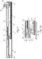
- Fig. 1 shows a feeder 1, which is in operative connection with a driver 90, in a retracted position.
- the driver 90 is fixedly connected to a sliding door, not shown here, for example via a screw connection.
- the feeder device 1 has a housing 20, each with an end face arranged screw receptacles 21 for the positive reception of mounting screws, with which the housing 20 can be fixedly attached to a piece of furniture.
- the housing 20 is open, that is shown without a cover provided for closing.
- the side surface 202 of the housing 20 and the cover are arranged parallel to a central longitudinal plane of the intake device 1.
- a damping device 30 is arranged in the longitudinal direction. Below the damping device 30 is parallel to a feed spring 40. Above the damping device 30, a carriage 50 is arranged, on which near the right end side of the housing 20, a coupling element 60 is pivotally mounted. At the end remote from the coupling element 60 end of the carriage 50 is a locking segment 80 in position to contact the carriage 50 in abutment connection. At the locking segment 80, an additional feed element 70 is attached to one end of a holding part 81. The opposite end of the additional pull-in element 70, which faces the coupling element 60, is connected to the housing 20.
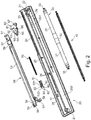
- Fig. 2 shows the individual components of the intake device 1 in a perspective view, which reveals details.
- the housing 20 has a longitudinally extending Dämpfvoriquessmethod 29.
- Dämpfvoriquessmethod 29 At the housing end side facing the end, adjacent to the A damping spring holder 23 is located underneath the damping device receptacle 29 and has a catch spring holder 22 at its end facing the housing end side.
- Above the Dämpfvoriquesstext 29 is a slide receptacle 24, in which the carriage 50 can be arranged to be movable in the longitudinal direction.
- a holder 25 for the additional feed element 70 and two stops 26, a guide web 27 and a guide element 28 are arranged.
- the damping device 30, which in Fig. 2 is shown in the fully retracted state, has two dampers 31 with cylinders, in each of which piston rods 34 are attenuating on an axis, but in opposite directions, movable. At the ends of the piston rods 34 each attachment pieces 33 are integrally formed.
- the dampers are linearly coupled via a connector 32.
- the carriage 50 has a coupling element receptacle 59 on its end facing the coupling element 60. At this there is a bearing 51 for movably receiving the coupling element 60.
- a base member 53 which is formed like a frame and without an inner wall extends. Also conceivable is an embodiment in which a wall is inserted within the frame.
- a shoulder 54 At the end of the carriage 50 facing away from the coupling element 60, there is a shoulder 54 in the upper part of the frame pointing in the direction of the housing wall. This forms a tension stop 55 pointing to the inside of the frame.
- a control element is provided on the front side 56 molded, which protrudes with a rounded end in the frame.
- the rounded end is axially spaced from the paragraph 55.
- a damper holder 58 and a spring holder 57 formed at the respective end of the carriage 50.
- the coupling element 60 is equipped with an abutment surface 61 and a blocking element 63, which together form a driver receptacle 62.
- it has a boom 65, at its end a guide projection 64 on both sides protrudes. From the end of the boom 65 also extends a spring arm 68 obliquely upwards and in the direction of the takeaway receiver 62. The possibility of movement of the spring arm is bounded above by a Arretieransatz 66.
- a bearing projection 67 for movably supporting the coupling element 60 in the bearing 51.
- the locking segment 80 is formed by an extending from the holding part 81 arm 82 elongated. On the arm 82, a projection 83 is formed in the direction of the end facing away from the holding part 81, which has a counter surface 831 and a control surface 832. At the end facing away from the holding part 81, the locking segment 80 has a bevel 84 and a downwardly directed nose 85.
- the figures show the intake device 1 in the transition from a closed to an open state of a furniture door, which may be in particular a sliding door. In the closing movement, the order is reversed.
- the coupling element 60 In the fully closed state, the coupling element 60 is in the retracted position ( Fig. 1 and 1a ). After the door has been slightly opened, the coupling element 60 passes an intermediate position ( Fig. 3 and 3a ), after which, when the door is partially or fully opened, a parking position ( 4 and 4a ).
- Fig. 1 and 1a It is in operative connection with a driver 90 of a sliding door in such a way that a power transmission between the driver 90 and the intake device 1 can take place as soon as a force is effective becomes.
- Both the pull-in spring 40 and the additional pull-in element 70 are minimally tensioned, ie they are in their shortest extent, yet they have a voltage.
- this voltage is obtained by the locking segment 80 with its holding part 81, to which one end of the additional Feeding device 70 is coupled, is seated on the stops 26.
- the tension could, for example, also be maintained by the abutment connection between the tension stop 55 and the mating surface 831.
- the arm 82 of the locking segment 80 is tilted such that the locking segment 80 rests linearly movable on the guide web 27 of the housing 20.
- the locking segment 80 is guided laterally in each case in a transverse axis extending orthogonally to the central longitudinal planes, from the side surface of the housing 20 and its lid.
- the locking segment 80 is supported on one side on a wall of the carriage 50 or another element.
- the decoupling is carried out by the guide member 28 mounted on the housing 20, on which the arresting segment 80 in motion with the carriage ascends with the bevel 84.
- the locking segment 80 is deflected downward.
- the force-transmitting stop connection between the voltage stop 55 and the counter surface 831 of the locking segment 80 is released.
- the locking segment 80 is brought into abutment with the housing 20 by the nose 85 engages over the end of the guide web 27.
- the guide web 27 is dimensioned such that it ends in this area and its end now serves as a stop surface.
- the retraction spring 40 is further charged with the opening movement.
- Charging takes place up to the in 4 and 4a shown parking position.
- the coupling segment 60 via a located in the cover of the housing 20 guide link, which is not shown here, tilted. In this way it releases the driver 90 and the furniture door is in freewheel.
- the coupling element 60 is locked and keeps the completely tensioned pull-in spring 40 under tension. In the parking position thus the feeder is completely charged.
- the coupling element 60 In the closing movement, the coupling element 60 initially captures the catch 90. He is steered by the impact of the parking position. The force of the pull-in spring 40, which is relatively high in this position by the wide clamping path, pulls the cam 90 in the direction of the closed state of the door. The movement is damped by the damping device 30, so that a harmonious closing movement. During the return to the closed position, the retraction spring 40 shortens and the closing force decreases. Upon reaching the intermediate position, the locking segment 80 is released from the housing 20. This is done via the control element 56 of the carriage 50, which ascends in the closing movement on the control surface 832 and thus releases the locking segment 80 from the abutment connection with the housing 20.
- Fig. 5 illustrates the effect of the insertion force F on the pull-in x.
- the pull-in force F1 applied by the pull-in spring 40 is effective from the parking position, where its amount is highest due to the wide pull-in path x. With decreasing pull-in distance x, the effective force F1 is reduced. From the intermediate position of the coupling element 60 F2 is now connected by the additional feed element 70. Due to the parallel connection, the forces add up to an increased pull-in force F1 + F2 compared to F1.
- FIG. 6 illustrates, not only an additional feed element 70, but also, for example, two may be provided in a feeder 1. This results in two intermediate positions at which an additional feed element 70 is connected in each case.
- an additional force F2 to the pull-in force F1 + F2 and finally another force F3 to the resulting pull-in force F1 + F2 + F3 are added to F1.
- additional additional collection devices are conceivable, which can be effective in the manner of a cascade circuit. In this way, an optimized retraction movement can be made possible in different areas of the retraction path x in order to ensure a secure closing of the furniture door with a high degree of operating convenience.
Landscapes
- Engineering & Computer Science (AREA)
- Mechanical Engineering (AREA)
- Closing And Opening Devices For Wings, And Checks For Wings (AREA)
Claims (14)
- Dispositif de rétraction (1) destiné à un meuble, comprenant un agencement de rétraction, qui présente un ressort de rétraction (40) et comprenant un dispositif d'amortissement (30),
dans lequel le ressort de rétraction (40) et le dispositif d'amortissement (30) sont reliés à un élément de couplage (60), indirectement ou directement, qui est réglage entre une position de repos et une position de rétraction,
dans lequel le dispositif de rétraction déplace l'élément de couplage (60) de la position de repos à la position de rétraction au moins par sections et le dispositif d'amortissement (30) amortit le mouvement de réglage de l'élément de couplage (60) de la position de repos à la position de rétraction, au moins par sections,
dans lequel l'agencement de rétraction présente au moins un élément de rétraction supplémentaire (70), qui applique une force de rétraction supplémentaire sur l'élément de couplage (60) à partir d'une position intermédiaire se trouvant entre la position de repos et la position de rétraction
et dans lequel une extrémité de l'élément de rétraction supplémentaire (70) est couplée à un segment de blocage (80), qui maintient l'élément de rétraction supplémentaire (70) sous tension et dans lequel l'autre extrémité de l'élément de rétraction supplémentaire (70) est couplée au boîtier (20).
dans lequel, dans un mouvement d'ouverture, le ressort de rétraction (40) et l'élément de rétraction supplémentaire (70) sont mis sous tension simultanément et sont chargés en énergie,
dans lequel la transmission de force est effectuée par le biais de l'élément de couplage (60), caractérisé en ce que l'élément de couplage (60) transmet la force par le biais d'une glissière (50) au ressort de rétraction (40) comme au segment de blocage (80) et, ainsi, à l'élément de rétraction supplémentaire (70). - Dispositif de rétraction (1) selon la revendication 1,
caractérisé en ce que
l'élément de rétraction supplémentaire (70) est un ressort secondaire agissant parallèlement au ressort de rétraction (40). - Dispositif de rétraction (1) selon la revendication 1 ou 2,
caractérisé en ce que
lorsque l'élément de couplage (60) se situe entre la position de rétraction et la position intermédiaire, l'élément de rétraction supplémentaire (70) est couplé à l'élément de couplage (60) par le biais de l'au moins un segment de blocage (80), dans lequel le segment de blocage (80) se déplace avec l'élément de couplage (60). - Dispositif de rétraction (1) selon une des revendications 1 à 3,
caractérisé en ce que
lorsque l'élément de couplage (60) se situe entre la position intermédiaire et la position de repos, l'élément de rétraction supplémentaire (70) est découpé de l'élément de couplage (60). - Dispositif de rétraction (1) selon une des revendications 1 à 4,
caractérisé en ce que
lorsque l'élément de couplage (60) se situe entre la position intermédiaire et la position de repos, l'élément de rétraction supplémentaire 70) est couplé au boîtier (20) par le biais du segment de blocage (80) et est maintenu en précontrainte de traction. - Dispositif de rétraction (1) selon une des revendications 1 à 5,
caractérisé en ce que
le segment de blocage (80) présente une pièce de retenue (81), à laquelle l'élément de rétraction supplémentaire (70) est couplé directement. - Dispositif de rétraction (1) selon une des revendications 1 à 6,
caractérisé en ce que
le segment de blocage (80) présente au moins un élément de commande (saillie (83) avec une surface de commande (832) ; chanfrein (84)), avec lequel le segment de blocage (80) peut être déplacé vers l'intérieur et/ou l'extérieur d'une position d'appui associée à la position intermédiaire au moyen d'un élément complémentaire (élément de commande (56) ; élément conducteur (28)). - Dispositif de rétraction (1) selon une des revendications 1 à 7,
caractérisé en ce que
le segment de blocage (80) présente une surface complémentaire (831) pour la formation d'une liaison de butée, par le biais de laquelle une transmission de force entre l'élément de couplage (60) et l'élément de rétraction supplémentaire (70) est effectuée lors du réglage de la position de rétraction vers la position intermédiaire et/ou inversement. - Dispositif de rétraction (1) selon une des revendications 1 à 8,
caractérisé en ce que
le segment de blocage (80) est bloqué au moyen d'une liaison de butée dans la position de retenue. - Dispositif de rétraction (1) selon une des revendications 1 à 9,
caractérisé en ce que
le boîtier (20) présente des éléments pour le guidage linéaire, pour la fixation et/ou pour la libération de la fixation du segment de blocage (80). - Dispositif de rétraction (1) selon une des revendications 1 à 10,
caractérisé en ce que
le ressort de rétraction (40) est couplé à l'élément de couplage (60), indirectement ou directement, de sorte que celui-ci reste dans la position de repos sous précontrainte de rappel. - Dispositif de rétraction (1) selon une des revendications 1 à 11,
caractérisé en ce que
l'élément de couplage (60) est couplé sur une glissière (50) et
en ce que la glissière (50) est couplée sur l'extrémité orientée à l'opposé de la position de rétraction du dispositif d'amortissement (30) ou la partie de réglage (cylindre, piston) tournée à l'opposé de la position de rétraction du dispositif d'amortissement (30). - Dispositif de rétraction (1) selon une des revendications 1 à 12,
caractérisé en ce que
l'élément de couplage (60) est disposé réglable dans le boîtier (20) et en ce que l'élément de couplage (60) est bougé dans la position de rétraction jusque dans la zone d'un côté de boîtier et, dans la position de repos, repose entre celui-ci et un côté de boîtier opposé. - Dispositif de rétraction (1) selon une des revendications 1 à 13,
caractérisé en ce que
le dispositif d'amortissement (60) présente un amortisseur linéaire et en ce que la direction d'action du ressort de rétraction (40) et du dispositif d'amortissement (60) sont parallèles l'une à l'autre.
Applications Claiming Priority (2)
| Application Number | Priority Date | Filing Date | Title |
|---|---|---|---|
| DE102014106796.7A DE102014106796A1 (de) | 2014-05-14 | 2014-05-14 | Einzugvorrichtung für Möbel |
| PCT/EP2015/060483 WO2015173244A1 (fr) | 2014-05-14 | 2015-05-12 | Dispositif de rétraction destiné à un meuble |
Publications (2)
| Publication Number | Publication Date |
|---|---|
| EP3142516A1 EP3142516A1 (fr) | 2017-03-22 |
| EP3142516B1 true EP3142516B1 (fr) | 2018-10-03 |
Family
ID=53274496
Family Applications (1)
| Application Number | Title | Priority Date | Filing Date |
|---|---|---|---|
| EP15725529.0A Not-in-force EP3142516B1 (fr) | 2014-05-14 | 2015-05-12 | Dispositif de rétraction destiné à un meuble |
Country Status (3)
| Country | Link |
|---|---|
| EP (1) | EP3142516B1 (fr) |
| DE (1) | DE102014106796A1 (fr) |
| WO (1) | WO2015173244A1 (fr) |
Families Citing this family (5)
| Publication number | Priority date | Publication date | Assignee | Title |
|---|---|---|---|---|
| DE102015114392A1 (de) * | 2015-08-28 | 2017-03-02 | Hettich-Heinze Gmbh & Co. Kg | Vorrichtung zum Positionieren von zwei Schiebetüren und Möbel |
| GB2563672A (en) * | 2017-06-23 | 2018-12-26 | Titus D O O Dekani | Improvements in damped closure mechanisms |
| DE102017123613A1 (de) | 2017-10-11 | 2019-04-11 | Paul Hettich Gmbh & Co. Kg | Einzugsvorrichtung und Verfahren zum Öffnen und Schließen eines bewegbaren Möbelteils |
| DE102018008204B4 (de) * | 2018-10-14 | 2020-06-04 | Günther Zimmer | Einzugsvorrichtung mit Auszugsunterstützung |
| DE102018008203B4 (de) * | 2018-10-14 | 2020-06-04 | Günther Zimmer | Selbsteinzugsvorrichtung mit Speicherladevorrichtung |
Citations (1)
| Publication number | Priority date | Publication date | Assignee | Title |
|---|---|---|---|---|
| WO2010143352A1 (fr) * | 2009-06-12 | 2010-12-16 | 高千穂交易株式会社 | Dispositif rentrant pour tiroir et dispositif de correction d'erreur |
Family Cites Families (7)
| Publication number | Priority date | Publication date | Assignee | Title |
|---|---|---|---|---|
| DE20217975U1 (de) * | 2002-11-20 | 2003-01-30 | Julius Blum Ges.m.b.H., Höchst | Einzugsvorrichtung für Schubladen |
| AT413187B (de) * | 2003-04-25 | 2005-12-15 | Blum Gmbh Julius | Einzugsvorrichtung für schubladen |
| DE202004006410U1 (de) | 2004-04-20 | 2005-09-01 | Alfit Ag | Einzugsautomatik mit Dämpfungsvorrichtung für Schubladen-Ausziehführungen |
| DE202004018189U1 (de) | 2004-11-23 | 2005-03-03 | Vauth-Sagel Holding Gmbh & Co. Kg | Einzugshilfe für einen Auszug |
| DE202009002715U1 (de) * | 2009-02-25 | 2010-07-15 | Paul Hettich Gmbh & Co. Kg | Auszugsführung für ein Möbelauszugsteil |
| DE102010000341A1 (de) | 2010-02-08 | 2011-08-11 | Karl Simon GmbH & Co. KG, 78733 | Einzugvorrichtung für Möbel |
| AT509540B1 (de) * | 2010-02-25 | 2012-05-15 | Blum Gmbh Julius | Ausziehführung für schubladen |
-
2014
- 2014-05-14 DE DE102014106796.7A patent/DE102014106796A1/de not_active Ceased
-
2015
- 2015-05-12 WO PCT/EP2015/060483 patent/WO2015173244A1/fr not_active Ceased
- 2015-05-12 EP EP15725529.0A patent/EP3142516B1/fr not_active Not-in-force
Patent Citations (1)
| Publication number | Priority date | Publication date | Assignee | Title |
|---|---|---|---|---|
| WO2010143352A1 (fr) * | 2009-06-12 | 2010-12-16 | 高千穂交易株式会社 | Dispositif rentrant pour tiroir et dispositif de correction d'erreur |
Also Published As
| Publication number | Publication date |
|---|---|
| WO2015173244A1 (fr) | 2015-11-19 |
| EP3142516A1 (fr) | 2017-03-22 |
| DE102014106796A1 (de) | 2015-11-19 |
Similar Documents
| Publication | Publication Date | Title |
|---|---|---|
| EP2661195B1 (fr) | Dispositif d'éjection verrouillable à mécanisme de surcharge | |
| AT512415B1 (de) | Zuziehvorrichtung für ein beweglich gelagertes Möbelteil | |
| DE102017107461A1 (de) | Bewegungsanordnung | |
| EP3141153B1 (fr) | Dispositif de deplacement d'un element de meuble mobile dans un sens d'ouverture par rapport a un corps d'un meuble | |
| EP3133232B1 (fr) | Dispositif de deplacement d'un element de meuble mobile et meuble comprenant un dispositif de deplacement d'un element de meuble mobile | |
| EP3076826B1 (fr) | Dispositif d'entraînement pour une pièce de meuble mobile | |
| EP3142516B1 (fr) | Dispositif de rétraction destiné à un meuble | |
| EP3341545B1 (fr) | Dispositif de positionnement de deux portes coulissantes et meuble | |
| EP2730734B1 (fr) | Dispositif d'entraînement bidirectionnel pour une porte coulissante médiane | |
| DE102013114309A1 (de) | Einzugs- und Dämpfungseinheit für ein Schiebeelement | |
| EP3518707A1 (fr) | Dispositif d'insertion pour système d'extraction de tiroir | |
| WO2010112522A1 (fr) | Dispositif d'escamotage | |
| DE202005011752U1 (de) | Dämpfungselement | |
| DE102011050605B4 (de) | Schiebeanordnung | |
| EP2534326B1 (fr) | Dispositif d'escamotage pour portes coulissants | |
| WO2011088481A1 (fr) | Dispositif d'entraînement pour tiroirs | |
| EP3062661B1 (fr) | Dispositif pour ouvrir une partie de meuble mobile | |
| DE102009021202A1 (de) | Einzugvorrichtung | |
| EP3563724B1 (fr) | Dispositif de fermeture d'une partie de meuble mobile | |
| DE202012008995U1 (de) | Möbel und Vorrichtung für die Bewegungsbeeinflussung eines Möbelteils | |
| DE102017107460A1 (de) | Bewegungsanordnung | |
| DE102018106984B4 (de) | Betätigungseinrichtung für einen Einschub sowie Gerät oder Möbelstück mit einer solchen Betätigungseinrichtung | |
| DE202010000143U1 (de) | Einzugvorrichtung für Schiebetüren |
Legal Events
| Date | Code | Title | Description |
|---|---|---|---|
| STAA | Information on the status of an ep patent application or granted ep patent |
Free format text: STATUS: THE INTERNATIONAL PUBLICATION HAS BEEN MADE |
|
| PUAI | Public reference made under article 153(3) epc to a published international application that has entered the european phase |
Free format text: ORIGINAL CODE: 0009012 |
|
| STAA | Information on the status of an ep patent application or granted ep patent |
Free format text: STATUS: REQUEST FOR EXAMINATION WAS MADE |
|
| 17P | Request for examination filed |
Effective date: 20161214 |
|
| AK | Designated contracting states |
Kind code of ref document: A1 Designated state(s): AL AT BE BG CH CY CZ DE DK EE ES FI FR GB GR HR HU IE IS IT LI LT LU LV MC MK MT NL NO PL PT RO RS SE SI SK SM TR |
|
| AX | Request for extension of the european patent |
Extension state: BA ME |
|
| DAV | Request for validation of the european patent (deleted) | ||
| DAX | Request for extension of the european patent (deleted) | ||
| STAA | Information on the status of an ep patent application or granted ep patent |
Free format text: STATUS: EXAMINATION IS IN PROGRESS |
|
| 17Q | First examination report despatched |
Effective date: 20171005 |
|
| REG | Reference to a national code |
Ref country code: DE Ref legal event code: R079 Ref document number: 502015006231 Country of ref document: DE Free format text: PREVIOUS MAIN CLASS: A47B0088400000 Ipc: A47B0088467000 |
|
| GRAP | Despatch of communication of intention to grant a patent |
Free format text: ORIGINAL CODE: EPIDOSNIGR1 |
|
| RIC1 | Information provided on ipc code assigned before grant |
Ipc: A47B 88/467 20170101AFI20180329BHEP Ipc: E05F 5/00 20170101ALI20180329BHEP Ipc: E05F 1/16 20060101ALI20180329BHEP |
|
| STAA | Information on the status of an ep patent application or granted ep patent |
Free format text: STATUS: GRANT OF PATENT IS INTENDED |
|
| INTG | Intention to grant announced |
Effective date: 20180503 |
|
| GRAS | Grant fee paid |
Free format text: ORIGINAL CODE: EPIDOSNIGR3 |
|
| GRAA | (expected) grant |
Free format text: ORIGINAL CODE: 0009210 |
|
| STAA | Information on the status of an ep patent application or granted ep patent |
Free format text: STATUS: THE PATENT HAS BEEN GRANTED |
|
| AK | Designated contracting states |
Kind code of ref document: B1 Designated state(s): AL AT BE BG CH CY CZ DE DK EE ES FI FR GB GR HR HU IE IS IT LI LT LU LV MC MK MT NL NO PL PT RO RS SE SI SK SM TR |
|
| REG | Reference to a national code |
Ref country code: GB Ref legal event code: FG4D Free format text: NOT ENGLISH |
|
| REG | Reference to a national code |
Ref country code: CH Ref legal event code: EP Ref country code: AT Ref legal event code: REF Ref document number: 1047692 Country of ref document: AT Kind code of ref document: T Effective date: 20181015 |
|
| REG | Reference to a national code |
Ref country code: IE Ref legal event code: FG4D Free format text: LANGUAGE OF EP DOCUMENT: GERMAN Ref country code: DE Ref legal event code: R096 Ref document number: 502015006231 Country of ref document: DE |
|
| REG | Reference to a national code |
Ref country code: NL Ref legal event code: MP Effective date: 20181003 |
|
| REG | Reference to a national code |
Ref country code: LT Ref legal event code: MG4D |
|
| PG25 | Lapsed in a contracting state [announced via postgrant information from national office to epo] |
Ref country code: NL Free format text: LAPSE BECAUSE OF FAILURE TO SUBMIT A TRANSLATION OF THE DESCRIPTION OR TO PAY THE FEE WITHIN THE PRESCRIBED TIME-LIMIT Effective date: 20181003 |
|
| PG25 | Lapsed in a contracting state [announced via postgrant information from national office to epo] |
Ref country code: LT Free format text: LAPSE BECAUSE OF FAILURE TO SUBMIT A TRANSLATION OF THE DESCRIPTION OR TO PAY THE FEE WITHIN THE PRESCRIBED TIME-LIMIT Effective date: 20181003 Ref country code: PL Free format text: LAPSE BECAUSE OF FAILURE TO SUBMIT A TRANSLATION OF THE DESCRIPTION OR TO PAY THE FEE WITHIN THE PRESCRIBED TIME-LIMIT Effective date: 20181003 Ref country code: NO Free format text: LAPSE BECAUSE OF FAILURE TO SUBMIT A TRANSLATION OF THE DESCRIPTION OR TO PAY THE FEE WITHIN THE PRESCRIBED TIME-LIMIT Effective date: 20190103 Ref country code: HR Free format text: LAPSE BECAUSE OF FAILURE TO SUBMIT A TRANSLATION OF THE DESCRIPTION OR TO PAY THE FEE WITHIN THE PRESCRIBED TIME-LIMIT Effective date: 20181003 Ref country code: IS Free format text: LAPSE BECAUSE OF FAILURE TO SUBMIT A TRANSLATION OF THE DESCRIPTION OR TO PAY THE FEE WITHIN THE PRESCRIBED TIME-LIMIT Effective date: 20190203 Ref country code: BG Free format text: LAPSE BECAUSE OF FAILURE TO SUBMIT A TRANSLATION OF THE DESCRIPTION OR TO PAY THE FEE WITHIN THE PRESCRIBED TIME-LIMIT Effective date: 20190103 Ref country code: CZ Free format text: LAPSE BECAUSE OF FAILURE TO SUBMIT A TRANSLATION OF THE DESCRIPTION OR TO PAY THE FEE WITHIN THE PRESCRIBED TIME-LIMIT Effective date: 20181003 Ref country code: ES Free format text: LAPSE BECAUSE OF FAILURE TO SUBMIT A TRANSLATION OF THE DESCRIPTION OR TO PAY THE FEE WITHIN THE PRESCRIBED TIME-LIMIT Effective date: 20181003 Ref country code: LV Free format text: LAPSE BECAUSE OF FAILURE TO SUBMIT A TRANSLATION OF THE DESCRIPTION OR TO PAY THE FEE WITHIN THE PRESCRIBED TIME-LIMIT Effective date: 20181003 Ref country code: FI Free format text: LAPSE BECAUSE OF FAILURE TO SUBMIT A TRANSLATION OF THE DESCRIPTION OR TO PAY THE FEE WITHIN THE PRESCRIBED TIME-LIMIT Effective date: 20181003 |
|
| PG25 | Lapsed in a contracting state [announced via postgrant information from national office to epo] |
Ref country code: GR Free format text: LAPSE BECAUSE OF FAILURE TO SUBMIT A TRANSLATION OF THE DESCRIPTION OR TO PAY THE FEE WITHIN THE PRESCRIBED TIME-LIMIT Effective date: 20190104 Ref country code: RS Free format text: LAPSE BECAUSE OF FAILURE TO SUBMIT A TRANSLATION OF THE DESCRIPTION OR TO PAY THE FEE WITHIN THE PRESCRIBED TIME-LIMIT Effective date: 20181003 Ref country code: AL Free format text: LAPSE BECAUSE OF FAILURE TO SUBMIT A TRANSLATION OF THE DESCRIPTION OR TO PAY THE FEE WITHIN THE PRESCRIBED TIME-LIMIT Effective date: 20181003 Ref country code: SE Free format text: LAPSE BECAUSE OF FAILURE TO SUBMIT A TRANSLATION OF THE DESCRIPTION OR TO PAY THE FEE WITHIN THE PRESCRIBED TIME-LIMIT Effective date: 20181003 Ref country code: PT Free format text: LAPSE BECAUSE OF FAILURE TO SUBMIT A TRANSLATION OF THE DESCRIPTION OR TO PAY THE FEE WITHIN THE PRESCRIBED TIME-LIMIT Effective date: 20190203 |
|
| REG | Reference to a national code |
Ref country code: DE Ref legal event code: R097 Ref document number: 502015006231 Country of ref document: DE |
|
| PG25 | Lapsed in a contracting state [announced via postgrant information from national office to epo] |
Ref country code: IT Free format text: LAPSE BECAUSE OF FAILURE TO SUBMIT A TRANSLATION OF THE DESCRIPTION OR TO PAY THE FEE WITHIN THE PRESCRIBED TIME-LIMIT Effective date: 20181003 Ref country code: DK Free format text: LAPSE BECAUSE OF FAILURE TO SUBMIT A TRANSLATION OF THE DESCRIPTION OR TO PAY THE FEE WITHIN THE PRESCRIBED TIME-LIMIT Effective date: 20181003 |
|
| PLBE | No opposition filed within time limit |
Free format text: ORIGINAL CODE: 0009261 |
|
| STAA | Information on the status of an ep patent application or granted ep patent |
Free format text: STATUS: NO OPPOSITION FILED WITHIN TIME LIMIT |
|
| PG25 | Lapsed in a contracting state [announced via postgrant information from national office to epo] |
Ref country code: RO Free format text: LAPSE BECAUSE OF FAILURE TO SUBMIT A TRANSLATION OF THE DESCRIPTION OR TO PAY THE FEE WITHIN THE PRESCRIBED TIME-LIMIT Effective date: 20181003 Ref country code: SM Free format text: LAPSE BECAUSE OF FAILURE TO SUBMIT A TRANSLATION OF THE DESCRIPTION OR TO PAY THE FEE WITHIN THE PRESCRIBED TIME-LIMIT Effective date: 20181003 Ref country code: EE Free format text: LAPSE BECAUSE OF FAILURE TO SUBMIT A TRANSLATION OF THE DESCRIPTION OR TO PAY THE FEE WITHIN THE PRESCRIBED TIME-LIMIT Effective date: 20181003 Ref country code: SK Free format text: LAPSE BECAUSE OF FAILURE TO SUBMIT A TRANSLATION OF THE DESCRIPTION OR TO PAY THE FEE WITHIN THE PRESCRIBED TIME-LIMIT Effective date: 20181003 |
|
| 26N | No opposition filed |
Effective date: 20190704 |
|
| PG25 | Lapsed in a contracting state [announced via postgrant information from national office to epo] |
Ref country code: SI Free format text: LAPSE BECAUSE OF FAILURE TO SUBMIT A TRANSLATION OF THE DESCRIPTION OR TO PAY THE FEE WITHIN THE PRESCRIBED TIME-LIMIT Effective date: 20181003 |
|
| REG | Reference to a national code |
Ref country code: CH Ref legal event code: PL |
|
| GBPC | Gb: european patent ceased through non-payment of renewal fee |
Effective date: 20190512 |
|
| PG25 | Lapsed in a contracting state [announced via postgrant information from national office to epo] |
Ref country code: MC Free format text: LAPSE BECAUSE OF FAILURE TO SUBMIT A TRANSLATION OF THE DESCRIPTION OR TO PAY THE FEE WITHIN THE PRESCRIBED TIME-LIMIT Effective date: 20181003 Ref country code: LI Free format text: LAPSE BECAUSE OF NON-PAYMENT OF DUE FEES Effective date: 20190531 Ref country code: CH Free format text: LAPSE BECAUSE OF NON-PAYMENT OF DUE FEES Effective date: 20190531 |
|
| REG | Reference to a national code |
Ref country code: BE Ref legal event code: MM Effective date: 20190531 |
|
| PG25 | Lapsed in a contracting state [announced via postgrant information from national office to epo] |
Ref country code: LU Free format text: LAPSE BECAUSE OF NON-PAYMENT OF DUE FEES Effective date: 20190512 |
|
| PG25 | Lapsed in a contracting state [announced via postgrant information from national office to epo] |
Ref country code: TR Free format text: LAPSE BECAUSE OF FAILURE TO SUBMIT A TRANSLATION OF THE DESCRIPTION OR TO PAY THE FEE WITHIN THE PRESCRIBED TIME-LIMIT Effective date: 20181003 |
|
| PG25 | Lapsed in a contracting state [announced via postgrant information from national office to epo] |
Ref country code: IE Free format text: LAPSE BECAUSE OF NON-PAYMENT OF DUE FEES Effective date: 20190512 Ref country code: GB Free format text: LAPSE BECAUSE OF NON-PAYMENT OF DUE FEES Effective date: 20190512 |
|
| PG25 | Lapsed in a contracting state [announced via postgrant information from national office to epo] |
Ref country code: BE Free format text: LAPSE BECAUSE OF NON-PAYMENT OF DUE FEES Effective date: 20190531 |
|
| PG25 | Lapsed in a contracting state [announced via postgrant information from national office to epo] |
Ref country code: FR Free format text: LAPSE BECAUSE OF NON-PAYMENT OF DUE FEES Effective date: 20190531 |
|
| PG25 | Lapsed in a contracting state [announced via postgrant information from national office to epo] |
Ref country code: CY Free format text: LAPSE BECAUSE OF FAILURE TO SUBMIT A TRANSLATION OF THE DESCRIPTION OR TO PAY THE FEE WITHIN THE PRESCRIBED TIME-LIMIT Effective date: 20181003 |
|
| REG | Reference to a national code |
Ref country code: AT Ref legal event code: MM01 Ref document number: 1047692 Country of ref document: AT Kind code of ref document: T Effective date: 20200512 |
|
| PG25 | Lapsed in a contracting state [announced via postgrant information from national office to epo] |
Ref country code: MT Free format text: LAPSE BECAUSE OF FAILURE TO SUBMIT A TRANSLATION OF THE DESCRIPTION OR TO PAY THE FEE WITHIN THE PRESCRIBED TIME-LIMIT Effective date: 20181003 Ref country code: HU Free format text: LAPSE BECAUSE OF FAILURE TO SUBMIT A TRANSLATION OF THE DESCRIPTION OR TO PAY THE FEE WITHIN THE PRESCRIBED TIME-LIMIT; INVALID AB INITIO Effective date: 20150512 |
|
| PG25 | Lapsed in a contracting state [announced via postgrant information from national office to epo] |
Ref country code: AT Free format text: LAPSE BECAUSE OF NON-PAYMENT OF DUE FEES Effective date: 20200512 |
|
| PG25 | Lapsed in a contracting state [announced via postgrant information from national office to epo] |
Ref country code: MK Free format text: LAPSE BECAUSE OF FAILURE TO SUBMIT A TRANSLATION OF THE DESCRIPTION OR TO PAY THE FEE WITHIN THE PRESCRIBED TIME-LIMIT Effective date: 20181003 |
|
| PGFP | Annual fee paid to national office [announced via postgrant information from national office to epo] |
Ref country code: DE Payment date: 20220519 Year of fee payment: 8 |
|
| REG | Reference to a national code |
Ref country code: DE Ref legal event code: R119 Ref document number: 502015006231 Country of ref document: DE |
|
| PG25 | Lapsed in a contracting state [announced via postgrant information from national office to epo] |
Ref country code: DE Free format text: LAPSE BECAUSE OF NON-PAYMENT OF DUE FEES Effective date: 20231201 |