EP3142719B1 - Blutreservoir mit flüssigkeitsvolumenmessung auf der basis eines drucksensors - Google Patents
Blutreservoir mit flüssigkeitsvolumenmessung auf der basis eines drucksensors Download PDFInfo
- Publication number
- EP3142719B1 EP3142719B1 EP14729052.2A EP14729052A EP3142719B1 EP 3142719 B1 EP3142719 B1 EP 3142719B1 EP 14729052 A EP14729052 A EP 14729052A EP 3142719 B1 EP3142719 B1 EP 3142719B1
- Authority
- EP
- European Patent Office
- Prior art keywords
- blood
- blood reservoir
- fluid
- reservoir
- pressure sensor
- Prior art date
- Legal status (The legal status is an assumption and is not a legal conclusion. Google has not performed a legal analysis and makes no representation as to the accuracy of the status listed.)
- Active
Links
Images




Classifications
-
- G—PHYSICS
- G01—MEASURING; TESTING
- G01F—MEASURING VOLUME, VOLUME FLOW, MASS FLOW OR LIQUID LEVEL; METERING BY VOLUME
- G01F23/00—Indicating or measuring liquid level or level of fluent solid material, e.g. indicating in terms of volume or indicating by means of an alarm
- G01F23/14—Indicating or measuring liquid level or level of fluent solid material, e.g. indicating in terms of volume or indicating by means of an alarm by measurement of pressure
-
- A—HUMAN NECESSITIES
- A61—MEDICAL OR VETERINARY SCIENCE; HYGIENE
- A61M—DEVICES FOR INTRODUCING MEDIA INTO, OR ONTO, THE BODY; DEVICES FOR TRANSDUCING BODY MEDIA OR FOR TAKING MEDIA FROM THE BODY; DEVICES FOR PRODUCING OR ENDING SLEEP OR STUPOR
- A61M1/00—Suction or pumping devices for medical purposes; Devices for carrying-off, for treatment of, or for carrying-over, body-liquids; Drainage systems
- A61M1/02—Blood transfusion apparatus
- A61M1/024—Means for controlling the quantity of transfused blood, e.g. by weighing the container and automatic stopping of the transfusion after reaching a determined amount
-
- A—HUMAN NECESSITIES
- A61—MEDICAL OR VETERINARY SCIENCE; HYGIENE
- A61M—DEVICES FOR INTRODUCING MEDIA INTO, OR ONTO, THE BODY; DEVICES FOR TRANSDUCING BODY MEDIA OR FOR TAKING MEDIA FROM THE BODY; DEVICES FOR PRODUCING OR ENDING SLEEP OR STUPOR
- A61M1/00—Suction or pumping devices for medical purposes; Devices for carrying-off, for treatment of, or for carrying-over, body-liquids; Drainage systems
- A61M1/36—Other treatment of blood in a by-pass of the natural circulatory system, e.g. temperature adaptation, irradiation ; Extra-corporeal blood circuits
- A61M1/3621—Extra-corporeal blood circuits
- A61M1/3627—Degassing devices; Buffer reservoirs; Drip chambers; Blood filters
-
- A—HUMAN NECESSITIES
- A61—MEDICAL OR VETERINARY SCIENCE; HYGIENE
- A61M—DEVICES FOR INTRODUCING MEDIA INTO, OR ONTO, THE BODY; DEVICES FOR TRANSDUCING BODY MEDIA OR FOR TAKING MEDIA FROM THE BODY; DEVICES FOR PRODUCING OR ENDING SLEEP OR STUPOR
- A61M1/00—Suction or pumping devices for medical purposes; Devices for carrying-off, for treatment of, or for carrying-over, body-liquids; Drainage systems
- A61M1/36—Other treatment of blood in a by-pass of the natural circulatory system, e.g. temperature adaptation, irradiation ; Extra-corporeal blood circuits
- A61M1/3621—Extra-corporeal blood circuits
- A61M1/3666—Cardiac or cardiopulmonary bypass, e.g. heart-lung machines
-
- A—HUMAN NECESSITIES
- A61—MEDICAL OR VETERINARY SCIENCE; HYGIENE
- A61M—DEVICES FOR INTRODUCING MEDIA INTO, OR ONTO, THE BODY; DEVICES FOR TRANSDUCING BODY MEDIA OR FOR TAKING MEDIA FROM THE BODY; DEVICES FOR PRODUCING OR ENDING SLEEP OR STUPOR
- A61M1/00—Suction or pumping devices for medical purposes; Devices for carrying-off, for treatment of, or for carrying-over, body-liquids; Drainage systems
- A61M1/36—Other treatment of blood in a by-pass of the natural circulatory system, e.g. temperature adaptation, irradiation ; Extra-corporeal blood circuits
- A61M1/3693—Other treatment of blood in a by-pass of the natural circulatory system, e.g. temperature adaptation, irradiation ; Extra-corporeal blood circuits using separation based on different densities of components, e.g. centrifuging
-
- A—HUMAN NECESSITIES
- A61—MEDICAL OR VETERINARY SCIENCE; HYGIENE
- A61M—DEVICES FOR INTRODUCING MEDIA INTO, OR ONTO, THE BODY; DEVICES FOR TRANSDUCING BODY MEDIA OR FOR TAKING MEDIA FROM THE BODY; DEVICES FOR PRODUCING OR ENDING SLEEP OR STUPOR
- A61M2205/00—General characteristics of the apparatus
- A61M2205/33—Controlling, regulating or measuring
- A61M2205/3331—Pressure; Flow
-
- A—HUMAN NECESSITIES
- A61—MEDICAL OR VETERINARY SCIENCE; HYGIENE
- A61M—DEVICES FOR INTRODUCING MEDIA INTO, OR ONTO, THE BODY; DEVICES FOR TRANSDUCING BODY MEDIA OR FOR TAKING MEDIA FROM THE BODY; DEVICES FOR PRODUCING OR ENDING SLEEP OR STUPOR
- A61M2205/00—General characteristics of the apparatus
- A61M2205/33—Controlling, regulating or measuring
- A61M2205/3331—Pressure; Flow
- A61M2205/3334—Measuring or controlling the flow rate
-
- A—HUMAN NECESSITIES
- A61—MEDICAL OR VETERINARY SCIENCE; HYGIENE
- A61M—DEVICES FOR INTRODUCING MEDIA INTO, OR ONTO, THE BODY; DEVICES FOR TRANSDUCING BODY MEDIA OR FOR TAKING MEDIA FROM THE BODY; DEVICES FOR PRODUCING OR ENDING SLEEP OR STUPOR
- A61M2205/00—General characteristics of the apparatus
- A61M2205/33—Controlling, regulating or measuring
- A61M2205/3368—Temperature
-
- A—HUMAN NECESSITIES
- A61—MEDICAL OR VETERINARY SCIENCE; HYGIENE
- A61M—DEVICES FOR INTRODUCING MEDIA INTO, OR ONTO, THE BODY; DEVICES FOR TRANSDUCING BODY MEDIA OR FOR TAKING MEDIA FROM THE BODY; DEVICES FOR PRODUCING OR ENDING SLEEP OR STUPOR
- A61M2205/00—General characteristics of the apparatus
- A61M2205/33—Controlling, regulating or measuring
- A61M2205/3379—Masses, volumes, levels of fluids in reservoirs, flow rates
- A61M2205/3389—Continuous level detection
-
- A—HUMAN NECESSITIES
- A61—MEDICAL OR VETERINARY SCIENCE; HYGIENE
- A61M—DEVICES FOR INTRODUCING MEDIA INTO, OR ONTO, THE BODY; DEVICES FOR TRANSDUCING BODY MEDIA OR FOR TAKING MEDIA FROM THE BODY; DEVICES FOR PRODUCING OR ENDING SLEEP OR STUPOR
- A61M2205/00—General characteristics of the apparatus
- A61M2205/35—Communication
- A61M2205/3576—Communication with non implanted data transmission devices, e.g. using external transmitter or receiver
- A61M2205/3592—Communication with non implanted data transmission devices, e.g. using external transmitter or receiver using telemetric means, e.g. radio or optical transmission
-
- A—HUMAN NECESSITIES
- A61—MEDICAL OR VETERINARY SCIENCE; HYGIENE
- A61M—DEVICES FOR INTRODUCING MEDIA INTO, OR ONTO, THE BODY; DEVICES FOR TRANSDUCING BODY MEDIA OR FOR TAKING MEDIA FROM THE BODY; DEVICES FOR PRODUCING OR ENDING SLEEP OR STUPOR
- A61M2205/00—General characteristics of the apparatus
- A61M2205/50—General characteristics of the apparatus with microprocessors or computers
-
- A—HUMAN NECESSITIES
- A61—MEDICAL OR VETERINARY SCIENCE; HYGIENE
- A61M—DEVICES FOR INTRODUCING MEDIA INTO, OR ONTO, THE BODY; DEVICES FOR TRANSDUCING BODY MEDIA OR FOR TAKING MEDIA FROM THE BODY; DEVICES FOR PRODUCING OR ENDING SLEEP OR STUPOR
- A61M2205/00—General characteristics of the apparatus
- A61M2205/50—General characteristics of the apparatus with microprocessors or computers
- A61M2205/502—User interfaces, e.g. screens or keyboards
-
- A—HUMAN NECESSITIES
- A61—MEDICAL OR VETERINARY SCIENCE; HYGIENE
- A61M—DEVICES FOR INTRODUCING MEDIA INTO, OR ONTO, THE BODY; DEVICES FOR TRANSDUCING BODY MEDIA OR FOR TAKING MEDIA FROM THE BODY; DEVICES FOR PRODUCING OR ENDING SLEEP OR STUPOR
- A61M2205/00—General characteristics of the apparatus
- A61M2205/60—General characteristics of the apparatus with identification means
- A61M2205/6018—General characteristics of the apparatus with identification means providing set-up signals for the apparatus configuration
-
- A—HUMAN NECESSITIES
- A61—MEDICAL OR VETERINARY SCIENCE; HYGIENE
- A61M—DEVICES FOR INTRODUCING MEDIA INTO, OR ONTO, THE BODY; DEVICES FOR TRANSDUCING BODY MEDIA OR FOR TAKING MEDIA FROM THE BODY; DEVICES FOR PRODUCING OR ENDING SLEEP OR STUPOR
- A61M2205/00—General characteristics of the apparatus
- A61M2205/60—General characteristics of the apparatus with identification means
- A61M2205/6063—Optical identification systems
Definitions
- the disclosure relates generally to perfusion and autotransfusion systems and more particularly to a blood reservoir having a pressure sensor.
- Perfusion entails encouraging physiological solutions, such as blood, through vessels in the body or some portion of the body of a human or other animal.
- Perfusion can be employed in intracorporeal and extracorporeal circulation, such as during cardiopulmonary bypass surgery and other surgeries and during various therapeutic treatments.
- Perfusion is useful in maintaining the viability of body parts, such as specific organs or limbs, while the body part remains within the body or while the body part is exterior to the body, such as for transplantation or temporarily removal of a body part to provide access to other body structures.
- Perfusion can be used for a short period of time, such as less than about six hours, or for extended periods of time, such as greater than about six hours.
- blood perfusion systems include one or more pumps in an extracorporeal circuit that is interconnected with the vascular system of a patient.
- cardiopulmonary bypass (CPB) surgery utilizes a perfusion system that allows for the temporary cessation of the heart by replacing the functions of the heart and lungs, which creates a still operating field and allows for the surgical correction of problems, such as vascular stenosis, valvular disorders, and congenital heart and great vessel defects.
- Perfusion systems for cardiopulmonary bypass surgery include an extracorporeal blood circuit that includes at least one pump and an oxygenation device to replace the functions of the heart and lungs.
- oxygen-poor blood is gravity-drained or vacuum suctioned from a large vein entering the heart or from other veins (e.g., a femoral vein) in the body and transferred through a venous line in the extracorporeal circuit.
- the venous blood is pumped to an oxygenator that provides for oxygen transfer to the blood.
- Oxygen may be introduced into the blood by transfer across a membrane or, less frequently, by bubbling oxygen through the blood. Concurrently, carbon dioxide is removed across the membrane.
- the oxygenated blood is then returned through an arterial line to the aorta, femoral, or other main artery. Medical personnel configure the perfusion system prior to each bypass procedure, which can be a time consuming process that entails significant manual input of information related to components of the system.
- WO 2007/018513 A1 relates to the measurement of blood level or volume in blood reservoirs.
- the following prior art documents relate to the measurement of fluid level or volume in other fluid reservoirs: US 6 542 848 B1 , US 4 782 451 A , WO 2006/122282 A2 , US 4 602 344 A , US 6 345 214 B1 , FR 2 811 752 A1 , US 2012/067133 A1 , US 2003/033871 A1 , US 5 604 315 A , US 2007/194981 A1 .
- Example 1 is a system including a fluid reservoir, a differential pressure sensor, and a controller.
- the fluid reservoir has a bottom and is to hold a fluid.
- the differential pressure sensor is coupled to the bottom of the fluid reservoir and to sense a pressure difference between pressure exerted on the differential pressure sensor by the fluid and pressure exerted on the fluid in the fluid reservoir and to provide at least one signal that indicates a fluid level in the fluid reservoir.
- the controller is to receive the at least one signal and determine a fluid volume in the fluid reservoir based on the at least one signal.
- the controller is to provide at least one of a fluid level signal that indicates the fluid level in the fluid reservoir and a fluid volume signal that indicates the fluid volume in the fluid reservoir.
- Example 2 the system of Example 1 in which the differential pressure sensor has a first side to sense the pressure exerted on the differential pressure sensor by the fluid and a second side open to the atmosphere to sense atmospheric pressure.
- Example 3 the system of any of Examples 1 and 2 in which the differential pressure sensor has a first side to sense the pressure exerted on the differential pressure sensor by the fluid and a second side fluidically coupled to the top of the fluid reservoir to sense the pressure exerted on the fluid in the fluid reservoir.
- Example 4 the system of any of Examples 1-3 in which the differential pressure sensor includes a first sensor to sense the pressure exerted on the differential pressure sensor by the fluid and a second sensor to sense the pressure exerted on the fluid in the fluid reservoir.
- Example 5 the system of any of Examples 1-4 in which the at least one of the fluid level signal that indicates the fluid level in the fluid reservoir and the fluid volume signal that indicates the fluid volume in the fluid reservoir is received by a heart lung machine that adjusts an operating parameter of the heart lung machine based on the at least one of the fluid level signal that indicates the fluid level in the fluid reservoir and the fluid volume signal that indicates the fluid volume in the fluid reservoir.
- Example 6 the system of any of Examples 1-5 in which the at least one of the fluid level signal that indicates the fluid level in the fluid reservoir and the fluid volume signal that indicates the fluid volume in the fluid reservoir is received by a display system that displays at least one of the fluid level in the fluid reservoir and the fluid volume in the fluid reservoir.
- Example 7 the system of any of Examples 1-6 in which the differential pressure sensor is integrated into the bottom of the fluid reservoir.
- Example 8 the system of any of Examples 1-7 in which the differential pressure sensor is one of snap fit and adhesively attached to the bottom of the fluid reservoir.
- Example 9 the system of any of Examples 1-8 in which the differential pressure sensor is disposable.
- Example 10 the system of any of Examples 1-9 in which the controller is part of a heart lung machine.
- Example 11 the system of any of Examples 1-10 in which the controller is part of a display system.
- Example 12 the system of any of Examples 1-11 in which the controller is part of the differential sensor.
- Example 13 is a sensor system including a first pressure sensor, a second pressure sensor, and a controller.
- the first pressure sensor is coupled to a fluid reservoir that holds a fluid and has a bottom.
- the first pressure sensor is coupled to the bottom of the fluid reservoir and is to provide a first signal that indicates hydrostatic pressure exerted by the fluid on the first pressure sensor.
- the second pressure sensor is to provide a second signal that indicates pressure exerted on the fluid in the fluid reservoir.
- the controller is to determine at least one of a fluid level in the fluid reservoir and a fluid volume in the fluid reservoir based on the first signal and the second signal.
- Example 14 the sensor system of Example 13 in which the second pressure sensor is open to the atmosphere to sense atmospheric pressure.
- Example 15 the sensor system of any of Examples 13 and 14 in which the second pressure sensor is coupled to the top of the fluid reservoir to sense the pressure exerted on the fluid in the fluid reservoir.
- Example 16 the sensor system of any of Examples 13-15 in which the first pressure sensor and the second pressure sensor are part of a differential pressure sensor.
- Example 17 is a method including providing a fluid reservoir having a bottom and providing a differential pressure sensor coupled to the bottom of the fluid reservoir.
- the differential pressure sensor sensing a pressure difference between pressure exerted on the differential pressure sensor by fluid in the fluid reservoir and pressure exerted on the fluid in the fluid reservoir, and providing at least one signal that indicates a level of the fluid in the fluid reservoir.
- a controller receiving the at least one signal and determining a fluid volume in the fluid reservoir based on the at least one signal.
- the controller providing at least one of a fluid level signal that indicates the fluid level in the fluid reservoir and a fluid volume signal that indicates the fluid volume in the fluid reservoir.
- Example 18 the method of Example 17 in which sensing a pressure difference includes sensing the pressure exerted on the differential pressure sensor by the fluid on a first side of the differential pressure sensor and sensing atmospheric pressure on a second side of the differential sensor.
- Example 19 the method of any of Examples 17 and 18 in which sensing a pressure difference includes sensing the pressure exerted on the differential pressure sensor by the fluid on a first side of the differential pressure sensor and sensing through fluidic coupling to the top of the fluid reservoir the pressure exerted on the fluid in the fluid reservoir.
- Example 20 the method of any of Examples 17-19 in which sensing a pressure difference includes sensing the pressure exerted on the differential pressure sensor by the fluid via a first sensor and sensing the pressure exerted on the fluid in the fluid reservoir via a second sensor.
- Embodiments shown and described herein can be described with reference to a blood level sensor system and/or a blood volume sensor system. As described herein, where the geometry of the blood reservoir is known, it is possible to provide either a fluid level or a fluid volume, as the volume of fluid in the reservoir can be calculated from the detected or sensed blood level and the known geometry of the reservoir.
- the disclosure relates to a perfusion system that is easy to set-up, use, and monitor during a bypass procedure, and the disclosure relates to an autotransfusion system.
- the disclosure relates to a sensor system that can be used to monitor a blood level or blood volume in a blood reservoir.
- the sensor system can be utilized in an integrated perfusion system in which the components are configured to communicate with the perfusion system.
- the sensor system can be utilized in a perfusion system lacking communication with components.
- the sensor system can be utilized in an autotransfusion system.
- the sensor system can be considered a blood level sensor system or a blood volume sensor system, where blood volume is ascertainable from blood level based on a known geometric configuration of the blood reservoir.
- FIG 1 is an illustration of an integrated perfusion system 10 including a heart lung machine (HLM) 12 and a disposable element 14. While a single disposable element 14 is shown, in some embodiments, a plurality of different disposable elements 14 can be utilized with the HLM 12. Also, one example of HLM components is shown in the HLM 12, in some embodiments, the HLM 12 can include other components and/or a different number of components.
- HLM heart lung machine
- the HLM 12 includes three pump modules 16. Each of the pump modules 16 can be used to provide fluid or gas for delivery to or removal from the heart chambers and/or a surgical field. In one example, one of the pump modules 16 draws blood from the heart, another provides surgical suction, and a third provides cardioplegia fluid (a high potassium solution to arrest the heart). Additional pump modules 16 (not shown) can be added to provide additional fluid transfer. In some embodiments, the HLM 12 includes as few as two pump modules 16 or as many as seven pump modules 16. In some embodiments, the pump modules 16 can be roller or peristaltic pumps. In some embodiments, one or more of the pump modules 16 can be a centrifugal pump.
- Each pump module 16 includes a corresponding control unit 18.
- each control unit 18 is configured to operate and monitor the operation of the corresponding pump module 16.
- each control unit 18 includes one or more input devices (not illustrated), such as switches, knobs, buttons, and touch screens, so the perfusionist can adjust the operation of the pump module 16.
- each pump module 16 includes an alphanumeric display that the control unit 18 uses to display, for example, the value of a setting, the value of a current operating parameter, and/or confirmation that the pump module 16 is operating normally.
- the HLM 12 includes a controller 20 in communication with the control units 18 and configured to operate the HLM 12.
- the controller 20 is configured to monitor one or more sensors in the HLM 12 and/or in the disposable element 14 to monitor operation of the HLM 12. Examples of sensors include flow meters, pressure sensors, temperature sensors, and blood gas analyzers.
- control units 18 and the controller 20 are illustrated as distinct elements, in some embodiments, these elements can be combined in a single controller. In some embodiments, one or more of the control units 18, in combination, can be configured to operate the HLM 12, thereby negating a need for the controller 20.
- the controller 20 communicates with an input device 22 and an output device 24.
- the input device 22 can be used by the perfusionist to enter information that is not otherwise entered into the control units 18.
- the output device 24 can be used by the HLM 12 to display pertinent information to the perfusionist.
- the input device 22 can be a key pad, a keyboard, and/or a touch screen.
- the output device 24 can be a monitor.
- the input device 22 and/or the output device 24 can be a computer, such as a personal computer, a laptop computer, a notebook computer, or a tablet computer.
- the input device 22 and the output device 24 can be in a single computer.
- the HLM 12 includes an RF sensor 26.
- the RF sensor 26 can be configured to receive information from an active RFID tag placed on the disposable element 14.
- the RF sensor 26 can be a hand held device that is used to scan a passive RFID tag on the disposable element 14.
- the RF sensor 26 can be replaced with any suitable wireless communication receiver.
- the disposable element 14 includes an RFID tag 28.
- the disposable element 14 includes an active RFID tag and/or a passive RFID tag configured to communicate with the RF sensor 26.
- the RFID tag 28 can be replaced with any suitable wireless communication transmitter.
- the system includes one or more of the RFID configurations disclosed in U.S. patent application 12/763,561, filed on April 20, 2010 , which is hereby incorporated by reference in its entirety.
- Passive RFID tags lack a power supply and, in some embodiments, are powered by an induced current caused by an incoming radio-frequency scan. Since passive RFID tags lack a power supply, they are smaller and less expensive than active RFID tags. Active RFID tags include an onboard power supply, such as a battery. While this increases the size and expense of the RFID tag, the active RFID tag can store more information and transmit further. RFID tags, whether active or passive, can be selected to transmit at a variety of frequencies depending on need. Options include low frequency (about 100 to 500 kilohertz), high frequency (about 10 to 15 megahertz), ultra high frequency (about 860 to 960 megahertz), and microwave frequency (about 2.45 gigahertz) RFID tags.
- the disposable element 14 can be one, two, or a plurality of different disposable elements that can be used in conjunction with the HLM 12.
- disposable elements 14 include tubing sets, blood reservoirs, oxygenators, heat exchangers, and arterial filters.
- a tubing set includes a number of different tubes, potentially of different lengths and/or sizes, for providing fluid flow between components of the HLM 12 as well as providing fluid flow between the HLM 12 and a patient.
- the disposable element 14 can be a blood reservoir such as a venous blood reservoir, a vent blood reservoir, or a cardiotomy or suction blood reservoir.
- the disposable element 14 can be a blood reservoir that combines one or more of a venous blood reservoir, a vent reservoir, and a suction reservoir in a single structure.
- one or more of the aforementioned sensors can be disposable elements that include an RFID tag 28 to provide information identifying the sensor and/or for transmitting sensed values to the controller 20.
- the RFID tag 28 can be attached to the disposable element 14 and programmed with or otherwise configured to include a variety of information pertaining to the disposable element 14.
- the RFID tag 28 can be adhesively secured to the disposable element 14.
- the RFID tag 28 can be molded into the disposable element 14.
- the RFID tag 28 can be a standalone card, similar in size and shape to a credit card, which can be packed with the disposable element 14 in such a way that it can be removed by the user and swiped by the RF sensor 26.
- the RFID tag 28 can include data or identifying information for the disposable element 14, such as the name of the particular disposable element 14, a reference code, a serial number, a lot number, and/or an expiration date. In some embodiments, this information may be communicated to the controller 20 and used to confirm that the proper disposable elements 14 are being used for a particular setting or patient. For example, the controller 20 may recognize that a pediatric tubing set is being used in combination with an adult-sized blood reservoir or the controller 20 may recognize that an expected component is missing. The controller 20 can recognize potential mismatches in equipment as a result of the information provided by the RFID tag 28 attached to each of the one or more disposable elements 14.
- the RFID tag 28 can include descriptive or design information for the disposable element 14, such as materials, a list of components, priming volume of a component or tubing circuit, tubing size, tubing length, minimum and maximum working pressures, minimum and maximum working volume, and blood reservoir sizing information, such as blood reservoir dimensions.
- this information can be communicated to the controller 20 and used by the controller 20 to at least partially configure and/or operate the HLM 12.
- the controller 20 can use the sizing information provided from each of the disposable elements 14 to determine a working blood volume for the HLM 12.
- information obtained from the RFID tag 28 can be provided to the perfusionist.
- the output device 24 can be configured to provide alphanumeric or graphical representations of the obtained information.
- the RFID tag 28 can include instructional information displayed by the output device 24 to instruct the perfusionist in optimal setup and/or operation of a disposable element 14.
- the output device 24 can be a computer such as a personal computer, a laptop computer, a notebook computer, or a tablet computer.
- the RFID tag 28 can include displayable information that, for example, suggests an optimal circuit design based upon the components being used or provides updated use instructions.
- information from the RFID tag 28 is displayed on an integrated data management system (DMS).
- DMS integrated data management system
- the RFID tag 28 can include information provided by a manufacturer of the disposable element 14, such as technical features of the disposable element 14 that have changed from a previous version or batch and/or information that can be displayed by the output device 24 that requires the user to acknowledge receipt of the information before the controller 20 proceeds with a procedure.
- the RFID tag 28 can receive error messages from the controller 20 and the RFID tag 28 can be returned to the manufacturer, thereby providing the manufacturer with feedback regarding the performance of the disposable element 14 as well as other components.
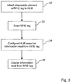
- FIG. 2 is a flow diagram illustrating a method that can be carried out using the perfusion system 10 of Figure 1 .
- a disposable element 14 having an RFID tag 28 is attached to the HLM 12.
- the RFID tag 28 is read, where the RFID tag 28 can be an active RFID tag or a passive RFID tag.
- the HLM 12 is configured based at least in part upon information that was read from the RFID tag 28.
- the controller 20 automatically configures the HLM 12 in response to the information.
- the RFID tag 28 can be read before the disposable element 14 is attached to the HLM 12.
- the RFID tag 28 can be read after the disposable element 14 is attached to the HLM 12.
- Figure 3 is a flow diagram illustrating a method that can be carried out using the perfusion system 10 of Figure 1 .
- the method of Figure 3 is the same as the method of Figure 2 , with the addition that, at 36, at least some of the information read from the RFID tag 28 can be displayed on the output device 24.
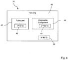
- FIG 4 is an illustration of a heart lung machine pack 38 that can be utilized with the perfusion system 10 of Figure 1 .
- the heart lung machine pack 38 can include all of the disposable elements 14 that will be used together for a patient and can be customized for the patient.
- the heart lung machine pack 38 can include a housing 40 that, once filled, can be sealed to keep the contents clean and sterile.
- the heart lung machine pack 38 includes a tubing set 42 and a disposable component 44.
- the tubing set 42 can include a plurality of different tubes.
- the disposable component 44 can be any of the disposable components discussed above with respect to the disposable element 14. In some embodiments, the heart lung machine pack 38 will include a plurality of different disposable components 44.
- the tubing set 42 includes a first RFID tag 46 while the disposable component 44 includes a second RFID tag 48.
- each of the first RFID tag 46 and the second RFID tag 48 can be either an active or a passive RFID tag and include readable information pertaining to the component to which it is attached.
- the housing 40 can include a third RFID tag 50 that, for example, identifies the contents of the heart lung machine pack 38.
- the first RFID tag 46 and the second RFID tag 48 will not be included and the third RFID tag 50 can be encoded with all of the information for the tubing set 42 and the disposable component 44.
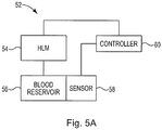
- Figure 5A is an illustration of a perfusion system 52.
- the perfusion system 52 can be similar to the perfusion system 10 of Figure 1 .
- the perfusion system 52 includes an HLM 54, a blood reservoir 56, a fluid sensor 58, and a controller 60.
- the HLM 54 can be similar to the HLM 12 (shown in Figure 1 ).
- the blood reservoir 56 can be a venous blood reservoir, a vent blood reservoir, or a cardiotomy or suction blood reservoir.
- the blood reservoir 56 can be a blood reservoir that combines one or more of a venous blood reservoir, a vent reservoir, and/or a suction reservoir in a single structure.
- the fluid sensor 58 can be configured to continuously monitor a variable blood level in the blood reservoir 56.
- the fluid sensor 58 provides one or more electrical signals that are proportional to the blood level in the blood reservoir 56.
- the fluid sensor 58 can be one or more pressure sensors for detecting the blood level in the blood reservoir 56.
- the fluid sensor 58 can be one or more pressure sensors that provide voltage signals that correlate to pressure signals for detecting the blood level in the blood reservoir 56.
- the fluid sensor 58 can be a differential pressure sensor that senses the difference between the hydrostatic pressure exerted on one side of the differential pressure sensor by the fluid in the blood reservoir and the pressure exerted on the fluid in the blood reservoir at, for example, the top of the blood reservoir and above the fluid.
- the fluid sensor 58 can be two pressure sensors, where a first pressure sensor senses the hydrostatic pressure exerted on the first pressure sensor by the fluid in the blood reservoir and a second pressure sensor senses the pressure exerted on the fluid in the blood reservoir at, for example, the top of the blood reservoir and above the fluid.
- the controller 60 can receive the one or more electrical signals from the fluid sensor 58 and determine or calculate the blood level and/or the blood volume in the blood reservoir 56.
- the controller 60 can determine or calculate the blood volume in the blood reservoir based on the one or more electrical signals as well as a known shape or geometry of the blood reservoir 56.
- the blood reservoir 56 can include an RFID tag (not illustrated) that provides the controller 60 with information pertaining to the known geometry of the blood reservoir 56.
- the volume of the blood reservoir is calculated according to one or more of the techniques described in U.S. patent application 12/763,561, filed on April 20, 2010 , previously incorporated by reference herein.
- the volume of the blood reservoir 56 is calculated by integrating the level of blood in the reservoir against the known cross-sectional area of the blood reservoir 56 at various heights throughout the blood reservoir 56.
- the known geometry of the blood reservoir 56 can include the cross-sectional area of the blood reservoir 56, or a width and depth of the blood reservoir 56 as well as details on how the cross-sectional area varies relative to height within the blood reservoir 56. If the blood reservoir 56 is a soft shell reservoir, the known geometry can be based at least in part upon a known lateral expansion rate of the soft shell reservoir relative to the blood level within the blood reservoir 56.
- FIG. 5B is an illustration of an autotransfusion system 300, according to some embodiments described in the disclosure.
- the autotransfusion system 300 includes a centrifuge 302, a pump 304, a sensor 306, and a controller 308.
- the controller 308 is operatively connected to the centrifuge 302, the pump 304, and the sensor 306 to provide the autotransfusion system 300.
- the controller 308 is communicatively coupled to the centrifuge 302 through a first communications path 310, to the pump 304 through a second communications path 312, and to the sensor 306 through a third communications path 314.
- the autotransfusion system 300 further includes: a salvaged blood reservoir 316, a salvaged blood fluid sensor 318, and a salvaged blood valve 320; a wash solution container 322, a wash solution fluid sensor 324, and a wash solution valve 326; a collection bag 328, a collection fluid sensor 330, and a collection valve 332; and a waste container 334 and a waste fluid sensor 336.
- the autotransfusion system 300 includes at least one but not all of the fluid sensors 318, 324, 330, and 336.
- the controller 308 is operatively connected to each of the salvaged blood fluid sensor 318, the salvaged blood valve 320, the wash solution fluid sensor 324, the wash solution valve 326, the collection fluid sensor 330, the collection valve 332, and the waste fluid sensor 336.
- the controller 308 is communicatively coupled (not shown for clarity) to each of the salvaged blood fluid sensor 318, the salvaged blood valve 320, the wash solution fluid sensor 324, the wash solution valve 326, the collection fluid sensor 330, the collection valve 332, and the waste fluid sensor 336.
- an inlet line 338 suctions salvaged blood from an operation field of a patient or from another blood source and carries the suctioned blood to the salvaged blood reservoir 316.
- the salvaged blood in the salvaged blood reservoir 316 is pumped through a salvaged blood line 340 and the salvaged blood valve 320 into a system line 342 by the pump 304.
- the salvaged blood is further pumped through a bowl inlet line 344 into a centrifuge bowl 346 in the centrifuge 302 by the pump 304.
- the salvaged blood valve 320 is open and the other valves, including the wash solution valve 326 and the collection valve 332, are closed.
- the centrifuge bowl 346 receives the shed or salvaged blood directly from the operation field or directly from the other source.
- the centrifuge bowl 346 is filled with the salvaged blood as the centrifuge 302 rotates or spins the centrifuge bowl 346.
- the spinning centrifuge bowl 346 separates the blood into components according to the relative densities of the components.
- the red blood cells which are the densest components of the blood, are propelled outward, against the circumferential wall of the centrifuge bowl 346.
- Other components such as white blood cells and platelets, are arranged in a thin layer, referred to as the buffy coat, directly adjacent the concentrated mass of red blood cells.
- a plasma layer that includes undesirable components is situated above the buffy coat.
- the centrifuge bowl 346 As filling the centrifuge bowl 346 continues, more of the red blood cells are pushed upward along the circumferential wall of the centrifuge bowl 346, which pushes the plasma layer out of an outlet at the top of the centrifuge bowl 346.
- the plasma flows through a first waste line 348 connected to the outlet of the centrifuge bowl 346, past the sensor 306, and through a second waste line 350 into the waste container 334.
- the sensor 306 senses when the buffy coat begins to come out of the outlet or when the buffy coat is at or near the top of the centrifuge bowl 346 and the sensor 306 provides a corresponding signal to the controller 308. In response to the signal from the sensor 306, the controller 308 stops the fill phase.
- the autotransfusion system 300 washes the blood in the centrifuge bowl 346 in a wash phase.
- Wash solution contained in the wash solution container 322 is pumped into the centrifuge bowl 346 by the pump 304.
- the wash solution is pumped through a wash solution line 352 and the wash solution valve 326 into the system line 342 by the pump 304.
- the wash solution is further pumped through the bowl inlet line 344 and into the centrifuge bowl 346 by the pump 304.
- the wash solution valve 326 is open and the other valves, including the salvaged blood valve 320 and the collection valve 332, are closed.
- the wash solution is a saline solution.
- the controller 308 controls the centrifuge bowl 346 and the pump 304 to wash the blood in the centrifuge bowl 346.
- the controller 308 controls the centrifuge bowl 346 and the pump 304 to wash the blood in the centrifuge bowl 346.
- more of the plasma or supernatant that includes the undesirable components is removed and flows through the first waste line 348 connected to the outlet of the centrifuge bowl 346, past the sensor 306, and through the second waste line 350 and into the waste container 334.
- the final product is pumped out of the centrifuge bowl 346 through the bowl inlet line 344 and into the system line 342 by the pump 304.
- the final product is further pumped through the collection valve 332 and the collection line 354 into the collection bag 328.
- the controller 308 opens the collection valve 332 and closes the other valves, including the salvaged blood valve 320 and the wash solution valve 326.
- the final product of concentrated red blood cells in the collection bag 328 can be used for reinfusion back into the patient via outlet line 356.
- Each of the fluid sensors 318, 324, 330, and 336 can be configured to continuously monitor a variable fluid level in its corresponding container or bag 316, 322, 328, and 334.
- Each of the fluid sensors 318, 324, 330, and 336 provides one or more electrical signals that are proportional to the fluid level in its corresponding container or bag 316, 322, 328, and 334.
- each of the fluid sensors 318, 324, 330, and 336 can be one or more pressure sensors for detecting the fluid level in its corresponding container or bag 316, 322, 328, and 334.
- each of the fluid sensors 318, 324, 330, and 336 can be one or more pressure sensors that provide voltage signals that correlate to pressure signals for detecting the fluid level in its corresponding container or bag 316, 322, 328, and 334.
- each of the fluid sensors 318, 324, 330, and 336 can be a differential pressure sensor that senses the difference between the hydrostatic pressure exerted on one side of the differential pressure sensor by the fluid in its corresponding container or bag 316, 322, 328, and 334 and the pressure exerted on the fluid at, for example, the top of its corresponding container or bag 316, 322, 328, and 334 and above the fluid.
- each of the fluid sensors 318, 324, 330, and 336 can be two pressure sensors, where a first pressure sensor senses the hydrostatic pressure exerted on the first pressure sensor by the fluid in its corresponding container or bag 316, 322, 328, and 334 and a second pressure sensor senses the pressure exerted on the fluid at, for example, the top of its corresponding container or bag 316, 322, 328, and 334 and above the fluid.
- the controller 308 can receive the one or more electrical signals from each of the fluid sensors 318, 324, 330, and 336 and determine or calculate the fluid level and/or the fluid volume in its corresponding container or bag 316, 322, 328, and 334.
- the controller 308 can determine or calculate the fluid volume based on the one or more electrical signals as well as a known shape or geometry of the corresponding container or bag 316, 322, 328, and 334.
- one or more of the containers or bags 316, 322, 328, and 334 includes an RFID tag (not illustrated) that provides the controller 308 with information pertaining to the known geometry of the container or bag.
- the volume of the container or bag 316, 322, 328, and 334 is calculated according to one or more of the techniques described in U.S. patent application 12/763,561, filed on April 20, 2010 , previously incorporated by reference herein. In some embodiments, the volume of the container or bag 316, 322, 328, and 334 is calculated by integrating the level of fluid against the known cross-sectional area of the container or bag 316, 322, 328, and 334 at various heights throughout the container or bag 316, 322, 328, and 334.
- the known geometry can include the cross-sectional area of the container or bag 316, 322, 328, and 334, or a width and depth of the container or bag 316, 322, 328, and 334 as well as details on how the cross-sectional area varies relative to height within the container or bag 316, 322, 328, and 334. If the container or bag 316, 322, 328, and 334 is a soft shell reservoir, the known geometry can be based at least in part upon a known lateral expansion rate of the soft shell reservoir relative to the fluid level within the container or bag 316, 322, 328, and 334.
- the auto transfusion system 300 can include one or more of the blood reservoir systems 70, 110, 150, and 190, described herein, to take the place of one or more of the fluid sensors 318, 324, 330, and 336 and the corresponding containers or bags 316, 322, 328, and 334.
- the term blood reservoir can include one or more of the salvaged blood reservoir 316, the wash solution container 322, the collection bag 328, and the waste container 334.
- the term fluid reservoir can include one or more of the blood reservoirs 72, 112, 156, and 196 in the blood reservoir systems 70, 110, 150, and 190 and the salvaged blood reservoir 316, the wash solution container 322, the collection bag 328, and the waste container 334.
- FIGs 6 and 7 are illustrations of a blood reservoir system 70 that can be used in a perfusion system, such as the perfusion system 10 of Figure 1 and the perfusion system 52 of Figure 5A .
- the blood reservoir system 70 can also be used in an autotransfusion system, such as autotransfusion system 300 of Figure 5B .
- the blood reservoir system 70 includes a blood reservoir 72 and a sensor system 74 that includes a differential pressure sensor 76 and a controller 78.
- the blood reservoir 72 can be similar to the blood reservoir 56.
- the differential pressure sensor 76 can be similar to the fluid sensor 58.
- the controller 78 can be similar to the controller 60.
- Figure 6 is an illustration of the blood reservoir system 70 with the blood reservoir 72 "open” to the atmosphere, such as when draining a patient by gravity.
- Figure 7 is an illustration of the blood reservoir system 70 with the blood reservoir 72 "closed” and fluidically coupled to a vacuum, such as when draining a patient with vacuum.
- the blood reservoir 72 is a rigid, hard shell blood reservoir.
- the blood reservoir 72 is illustrated containing a volume of fluid 80, such as blood, that defines an interface 82 between the volume of fluid 80 and the air or other gas 84 in the space above the volume of fluid 80 in the blood reservoir 72.
- the blood reservoir 72 can include a first opening 86 that can be left open to the atmosphere, as shown in Figure 6 , or fluidically coupled to a vacuum, as shown in Figure 7 , a second opening 88 that can be an inlet for the fluid, and a third opening 90 that can be an outlet for the fluid.
- the blood reservoir 72 can be a rigid, hard shell blood reservoir with a known geometry that can include the cross-sectional area of the blood reservoir 72, or a width and depth of the blood reservoir 72, as well as details on how the cross-sectional area varies relative to height within the blood reservoir 72.
- the differential pressure sensor 76 can be located at the bottom 92 of the blood reservoir 72 to sense the pressure difference between the pressure exerted on the differential pressure sensor 76 by the fluid in the blood reservoir 72 and the pressure exerted on the volume of fluid 80 from the air or other gas 84 above the volume of fluid 80 in the blood reservoir 72.
- the differential pressure sensor 76 provides a signal that indicates the fluid level in the blood reservoir 72 and the controller 78 determines or calculates the fluid volume based on the fluid level and the known geometric configuration of the blood reservoir 72.
- a first side 94 of the differential pressure sensor 76 can be in contact with the volume of fluid 80 in the blood reservoir 72 to sense the hydrostatic pressure exerted on the first side 94 of the differential pressure sensor 76 by the volume of fluid 80.
- a second side 96 of the differential pressure sensor 76 can be left open to the atmosphere to sense the atmospheric pressure, which is the pressure exerted on the volume of fluid 80 from above the volume of fluid 80 in the blood reservoir 72 with the first opening 86 left open to the atmosphere.
- the second side 96 of the differential pressure sensor 76 can be fluidically coupled with a tube 98 to the top 100 of the blood reservoir 72, such that the second side 96 of the differential pressure sensor 76 is fluidically coupled to the air or other gas 84 above the volume of fluid 80 in the blood reservoir 72, to sense the pressure exerted on the volume of fluid 80 from above the volume of fluid 80 in the blood reservoir 72.
- the differential pressure sensor 76 can provide at least one electrical signal that correlates to the pressure difference and the pressures exerted on the first and second sides 94 and 96 of the differential pressure sensor 76, where the at least one electrical signal indicates the fluid level in the blood reservoir 72. In some embodiments, the differential pressure sensor 76 can provide at least one voltage signal that indicates the fluid level in the blood reservoir 72. In some embodiments, the differential pressure sensor 76 can provide the at least one electrical signal as a wired electrical signal(s). In some embodiments, the differential pressure sensor 76 can provide the at least one electrical signal as a wireless signal(s).
- the differential pressure sensor 76 can be integrated into the blood reservoir 72. In some embodiments, the differential pressure sensor 76 can be snap fit into the bottom of the blood reservoir 72. In some embodiments, the differential pressure sensor 76 can be adhesively attached to the bottom of the blood reservoir 72. In some embodiments, the differential pressure sensor 76 can be molded into the blood reservoir 72, such that the differential pressure sensor 76 can be at least partially protected by the plastic material of the blood reservoir 72.
- the differential pressure sensor 76 can include a single pressure sensing transducer or diaphragm that receives a first pressure on the first side 94 and a second pressure on the second side 96, and can provide an electrical signal that indicates the fluid level in the blood reservoir 72.
- the differential pressure sensor 76 includes a first pressure sensing transducer or diaphragm at first side 94 and a second pressure sensing transducer or diaphragm at second side 96 and can provide one or more electrical signals that indicate the fluid level in the blood reservoir 72.
- the differential pressure sensor 76 includes two pressure sensors in a package.
- the differential pressure sensor 76 can be disposable. In some embodiments, the differential pressure sensor 76 can be modeled after a disposable pressure sensor, such as Measurement Specialties 1620 model, which is a fully piezoresistive silicon pressure sensor for use in invasive blood pressure monitoring. The model 1620 can be used with automated assembly equipment and dropped directly into a disposable unit. Also, the model 1620 includes a dielectric gel placed over the sensor to provide electric and fluidic isolation and the model 1620 can be sterilized. In addition, the model 1620 has an operating product life of 168 hours and a shelf life of 5 years. In some embodiments, the differential pressure sensor 76 can be provided based on a micro-electromechanical system (MEMS) component, such as Measurement Specialties MS763 die.
- MEMS micro-electromechanical system
- the controller 78 can receive the at least one electrical signal from the differential pressure sensor 76 via communications path 102 and determine or calculate the fluid volume in the blood reservoir 72 based on the at least one electrical signal and the known geometric configuration of the blood reservoir 72.
- the controller 78 can provide at least one signal indicating at least one of: the fluid level in the blood reservoir 72 (a fluid level signal); and the fluid volume in the blood reservoir 72 (a fluid volume signal).
- an HLM such as the HLM 12 (shown in Figure 1 ) or the HLM 54 (shown in Figure 5A ), can receive the at least one signal from the controller 78 and adjust an operating parameter of the HLM based on the at least one of the fluid level signal and the fluid volume signal.
- a system such as the DMS, can receive the at least one signal from the controller 78 and display at least one of the fluid level and the fluid volume in the blood reservoir 72.
- controller 78 is shown as a distinct element and can be a standalone controller, in some embodiments, the controller 78 can be part of an HLM or part of a controller (similar to the controller 20) operating an HLM. Also, in some embodiments, the controller 78 can be part of the differential pressure sensor 76 or part of a display system, such as the DMS.
- the first opening 86 is open to the atmosphere and the differential pressure sensor 76 can sense the hydrostatic pressure exerted on the first side 94 of the differential pressure sensor 76 by the fluid in the blood reservoir 72 and the atmospheric pressure exerted on the second side 96 of the differential pressure sensor 76, where the atmospheric pressure is the pressure exerted on the volume of fluid 80 from the air or atmosphere at 84 above the volume of fluid 80 in the blood reservoir 72.
- the differential pressure sensor 76 provides at least one electrical signal that indicates the fluid level in the blood reservoir 72.
- the controller 78 receives the at least one electrical signal from the differential pressure sensor 76 and determines the fluid volume in the blood reservoir 72 based on the at least one electrical signal and the known geometric configuration of the blood reservoir 72.
- the controller 78 provides at least one of a fluid level signal that indicates the fluid level in the blood reservoir 72 and a fluid volume signal that indicates the fluid volume in the blood reservoir 72.
- the first opening 86 is fluidically coupled to a vacuum and the second side 96 of the differential pressure sensor 76 is fluidically coupled to the air or other gas 84 above the volume of fluid 80 in the blood reservoir 72.
- the differential pressure sensor 76 can sense the hydrostatic pressure exerted on the first side 94 of the differential pressure sensor 76 by the fluid in the blood reservoir 72 and the pressure exerted on the volume of fluid 80 from the air or other gas 84 above the volume of fluid 80 via the tube 98 and the second side 96 of the differential pressure sensor 76.
- the differential pressure sensor 76 provides at least one electrical signal that indicates the fluid level in the blood reservoir 72.
- the controller 78 receives the at least one electrical signal from the differential pressure sensor 76 and determines the fluid volume in the blood reservoir 72 based on the at least one electrical signal and the known geometric configuration of the blood reservoir 72.
- the controller 78 provides at least one of a fluid level signal that indicates the fluid level in the blood reservoir 72 and a fluid volume signal that indicates the fluid volume in the blood reservoir 72.
- Figure 8 is an illustration of a blood reservoir system 110 that includes a soft shell blood reservoir 112 and a sensor system 114 that can be used in a perfusion system, such as the perfusion system 10 of Figure 1 and the perfusion system 52 of Figure 5A .
- the blood reservoir system 110 can also be used in an autotransfusion system, such as autotransfusion system 300 of Figure 5B .
- the sensor system 114 includes a differential pressure sensor 116 and a controller 118.
- the blood reservoir 112 can be similar to the blood reservoir 56.
- the differential pressure sensor 116 can be similar to the fluid sensor 58.
- the controller 118 can be similar to the controller 60.
- the soft shell blood reservoir 112 is illustrated containing a volume of fluid 120, such as blood, that defines an interface 122 between the volume of fluid 120 and the air or other gas 124 in the space above the volume of fluid 120 in the blood reservoir 112.
- the blood reservoir 112 can include a first opening 126 that can be an inlet for the fluid and a second opening 128 that can be an outlet for the fluid.
- the blood reservoir 112 can be a soft shell blood reservoir with a known geometry that can be based at least in part upon a known lateral expansion rate of the soft shell blood reservoir relative to the blood or fluid level within the blood reservoir 112.
- the differential pressure sensor 116 can be located at the bottom 130 of the blood reservoir 112 to sense the pressure difference between the pressure exerted on the differential pressure sensor 116 by the fluid in the blood reservoir 112 and the pressure exerted on the soft shell blood reservoir 112, which is the atmospheric pressure.
- the differential pressure sensor 116 provides a signal that indicates the fluid level in the soft shell blood reservoir 112 and the controller 118 determines or calculates the fluid volume based on the fluid level and the known geometric configuration of the soft shell blood reservoir 112.
- a first side 132 of the differential pressure sensor 116 can be in contact with the volume of fluid 120 in the blood reservoir 112 to sense the hydrostatic pressure exerted on the first side 132 of the differential pressure sensor 116 by the volume of fluid 120.
- a second side 134 of the differential pressure sensor 116 can be left open to the atmosphere to sense the atmospheric pressure.
- the differential pressure sensor 116 can provide at least one electrical signal that correlates to the pressure difference and the pressures exerted on the first and second sides 132 and 134 of the differential pressure sensor 116, where the at least one electrical signal indicates the fluid level in the blood reservoir 112. In some embodiments, the differential pressure sensor 116 can provide at least one voltage signal that indicates the fluid level in the blood reservoir 112. In some embodiments, the differential pressure sensor 116 can provide the at least one electrical signal as a wired electrical signal(s). In some embodiments, the differential pressure sensor 116 can provide the at least one electrical signal as a wireless signal(s).
- the differential pressure sensor 116 can be integrated into the blood reservoir 112. In some embodiments, the differential pressure sensor 116 can be snap fit into the bottom of the blood reservoir 112. In some embodiments, the differential pressure sensor 116 can be adhesively attached to the bottom of the blood reservoir 112. In some embodiments, the differential pressure sensor 116 can be molded into the blood reservoir 112, such that the differential pressure sensor 116 can be at least partially protected by the plastic material of the blood reservoir 112.
- the differential pressure sensor 116 can include a single pressure sensing transducer or diaphragm that receives a first pressure on the first side 132 and a second pressure on the second side 134, and can provide an electrical signal that indicates the fluid level in the blood reservoir 112.
- the differential pressure sensor 116 includes a first pressure sensing transducer or diaphragm at first side 132 and a second pressure sensing transducer or diaphragm at second side 134 and can provide one or more electrical signals that indicate the fluid level in the blood reservoir 112.
- the differential pressure sensor 116 includes two pressure sensors in a package.
- the differential pressure sensor 116 can be disposable. In some embodiments, the differential pressure sensor 116 can be modeled after a disposable pressure sensor, such as Measurement Specialties 1620 model, which is a fully piezoresistive silicon pressure sensor for use in invasive blood pressure monitoring.
- the model 1620 can be used with automated assembly equipment and dropped directly into a disposable unit.
- the model 1620 includes a dielectric gel placed over the sensor to provide electric and fluidic isolation and the model 1620 can be sterilized.
- the model 1620 has an operating product life of 168 hours and a shelf life of 5 years.
- the differential pressure sensor 116 can be provided based on a micro-electromechanical system (MEMS) component, such as Measurement Specialties MS763 die.
- MEMS micro-electromechanical system
- the controller 118 can receive the at least one electrical signal from the differential pressure sensor 116 via communications path 136 and determine or calculate the fluid volume in the blood reservoir 112 based on the at least one electrical signal and the known geometric configuration of the blood reservoir 112.
- the controller 118 can provide at least one signal indicating at least one of: the fluid level in the blood reservoir 112 (a fluid level signal); and the fluid volume in the blood reservoir 112 (a fluid volume signal).
- an HLM such as the HLM 12 (shown in Figure 1 ) or the HLM 54 (shown in Figure 5A ), can receive the at least one signal from the controller 118 and adjust an operating parameter of the HLM based on the at least one of the fluid level signal and the fluid volume signal.
- a system such as the DMS, can receive the at least one signal from the controller 118 and display at least one of the fluid level and the fluid volume in the blood reservoir 112.
- controller 118 is shown as a distinct element and can be a standalone controller, in some embodiments, the controller 118 can be part of an HLM or part of a controller (similar to the controller 20) operating an HLM. Also, in some embodiments, the controller 118 can be part of the differential pressure sensor 116 or part of a display system, such as the DMS.
- the differential pressure sensor 116 can sense the hydrostatic pressure exerted on the first side 132 of the differential pressure sensor 116 by the fluid in the blood reservoir 112 and the atmospheric pressure exerted on the second side 134 of the differential pressure sensor 116, where the atmospheric pressure is the pressure exerted on the soft shell blood reservoir 112.
- the differential pressure sensor 116 provides at least one electrical signal that indicates the fluid level in the blood reservoir 112.
- the controller 118 receives the at least one electrical signal from the differential pressure sensor 116 and determines the fluid volume in the blood reservoir 112 based on the at least one electrical signal and the known geometric configuration of the blood reservoir 112.
- the controller 118 provides at least one of a fluid level signal that indicates the fluid level in the blood reservoir 112 and a fluid volume signal that indicates the fluid volume in the blood reservoir 112.
- Figure 9 is an illustration of a blood reservoir system 150 that includes two separate pressure sensors, a first pressure sensor 152 and a second pressure sensor 154.
- the blood reservoir system 150 can be used in a perfusion system, such as the perfusion system 10 of Figure 1 and the perfusion system 52 of Figure 5A .
- the blood reservoir system 150 can also be used in an autotransfusion system, such as autotransfusion system 300 of Figure 5B .
- the blood reservoir system 150 includes a blood reservoir 156 and a sensor system 158 that includes the first pressure sensor 152, the second pressure sensor 154, and a controller 160.
- the blood reservoir system 150 can be used with the blood reservoir 156 "open” to the atmosphere, such as when draining a patient by gravity, and with the blood reservoir 156 "closed” and fluidically coupled to a vacuum, such as when draining a patient with vacuum.
- the blood reservoir 156 can be similar to the blood reservoir 56.
- one or both of the first and second pressure sensors 152 and 154 can be similar to the fluid sensor 58.
- the controller 160 can be similar to the controller 60.
- the blood reservoir 156 is a rigid, hard shell blood reservoir illustrated containing a volume of fluid 162, such as blood, that defines an interface 164 between the volume of fluid 162 and the air or other gas 166 in the space above the volume of fluid 162 in the blood reservoir 156.
- the blood reservoir 156 can include a first opening 168 that can be left open to the atmosphere or fluidically coupled to a vacuum, a second opening 170 that can be an inlet for the fluid, and a third opening 172 that can be an outlet for the fluid.
- the blood reservoir 156 can be a rigid, hard shell blood reservoir with a known geometry that can include the cross-sectional area of the blood reservoir 156, or a width and depth of the blood reservoir 156, as well as details on how the cross-sectional area varies relative to height within the blood reservoir 156.
- the first pressure sensor 152 can be located at the bottom 174 of the blood reservoir 156 and in contact with the volume of fluid 162 to sense the hydrostatic pressure exerted on the first pressure sensor 152 by the fluid in the blood reservoir 156.
- the second pressure sensor 154 can be located at the top 176 of the blood reservoir 156 and in contact with the air or other gas 166 to sense the pressure exerted on the volume of fluid 162 above the fluid in the blood reservoir 156.
- the second pressure sensor 154 can be left unattached to the blood reservoir 156 and open to the atmosphere to sense the atmospheric pressure, which is the pressure exerted on the volume of fluid 162 in the blood reservoir 156.
- the fluid level in the blood reservoir 156 can be determined from the pressure difference between the pressure sensed by the first pressure sensor 152 and the pressure sensed by the second pressure sensor 154, and the fluid volume can be determined based on the fluid level and the known geometric configuration of the blood reservoir 156.
- Each of the first and second pressure sensors 152 and 154 can provide at least one electrical signal, such as a voltage signal, that correlates to the pressure sensed by the pressure sensor, where the at least one electrical signal is proportional to or at least related to the fluid level and the fluid volume in the blood reservoir 156.
- one or both of the first and second pressure sensors 152 and 154 can provide the at least one electrical signal as a wired electrical signal(s).
- one or both of the first and second pressure sensors 152 and 154 can provide the at least one electrical signal as a wireless signal(s).
- each of the first and second pressure sensors 152 and 154 can be integrated into the blood reservoir 156.
- one or both of the first and second pressure sensors 152 and 154 can be snap fit into the blood reservoir 156.
- one or both of the first and second pressure sensors 152 and 154 can be adhesively attached to the blood reservoir 156.
- one or both of the first and second pressure sensors 152 and 154 can be molded into the blood reservoir 156, such that only a connector may be accessible outside the blood reservoir 156 and the pressure sensor can be at least partially protected by the plastic material of the blood reservoir 156.
- one or both of the first and second pressure sensors 152 and 154 can be disposable. In some embodiments, one or both of the first and second pressure sensors 152 and 154 can be modeled after a disposable pressure sensor, such as Measurement Specialties 1620 model, which is a fully piezoresistive silicon pressure sensor for use in invasive blood pressure monitoring.
- the model 1620 can be used with automated assembly equipment and dropped directly into a disposable unit. Also, the model 1620 includes a dielectric gel placed over the sensor to provide electric and fluidic isolation and the model 1620 can be sterilized. In addition, the model 1620 has an operating product life of 168 hours and a shelf life of 5 years.
- one or both of the first and second pressure sensors 152 and 154 can be provided based on a micro-electromechanical system (MEMS) component, such as Measurement Specialties MS763 die.
- MEMS micro-electromechanical system
- the controller 160 can receive the at least one electrical signal from each of the first and second pressure sensors 152 and 154 via communication paths 178 and 180, respectively.
- the controller 160 can determine or calculate at least one of a fluid level in the blood reservoir 156 and a fluid volume in the blood reservoir 156 based on the signals and the known geometry of the rigid, hard shell blood reservoir 156.
- the controller 160 can provide at least one signal indicating at least one of: the fluid level in the blood reservoir 156 (a fluid level signal); and the fluid volume in the blood reservoir 156 (a fluid volume signal).
- an HLM such as the HLM 12 (shown in Figure 1 ) or the HLM 54 (shown in Figure 5A ), can receive the at least one signal from the controller 160 and adjust an operating parameter of the HLM based on the at least one of the fluid level signal and the fluid volume signal.
- a system such as the DMS, can receive the at least one signal from the controller 160 and display at least one of the fluid level and the fluid volume in the blood reservoir 156.
- controller 160 is shown as a distinct element and can be a standalone controller, in some embodiments, the controller 160 can be part of an HLM or part of a controller (similar to the controller 20) operating an HLM. Also, in some embodiments, the controller 160 can be part of one or both of the first and second pressure sensors 152 and 154 or part of a display system, such as the DMS.
- the first pressure sensor 152 can sense the hydrostatic pressure exerted on the first pressure sensor 152 by the fluid in the blood reservoir 156 and the second pressure sensor 154 can sense the atmospheric pressure exerted on the volume of fluid 152 in the blood reservoir 156.
- each of the first and second pressure sensors 152 and 154 provides at least one electrical signal that indicates the pressure sensed by the pressure sensor.
- the controller 160 receives the signals from the first and second pressure sensors 152 and 154 and determines at least one of a fluid level in the blood reservoir 156 and a fluid volume in the blood reservoir 156 based on the received signals and the known geometry of the rigid, hard shell blood reservoir 156.
- the controller 160 provides at least one of a fluid level signal that indicates the fluid level in the blood reservoir 156 and a fluid volume signal that indicates the fluid volume in the blood reservoir 156.
- the first pressure sensor 152 can sense the hydrostatic pressure exerted on the first pressure sensor 152 by the fluid in the blood reservoir 156 and the second pressure sensor 154 can sense the pressure exerted on the volume of fluid 162 above the volume of fluid 162 under vacuum.
- each of the first and second pressure sensors 152 and 154 provides at least one electrical signal that indicates the pressure sensed by the pressure sensor.
- the controller 160 receives the signals from the first and second pressure sensors 152 and 154 and determines at least one of a fluid level in the blood reservoir 156 and a fluid volume in the blood reservoir 156 based on the received signals.
- the controller 160 provides at least one of a fluid level signal that indicates the fluid level in the blood reservoir 156 and a fluid volume signal that indicates the fluid volume in the blood reservoir 156.
- FIG 10 is an illustration of a blood reservoir system 190 that includes two separate pressure sensors, a first pressure sensor 192 and a second pressure sensor 194, and a soft shell blood reservoir 196.
- the blood reservoir system 190 can be used in a perfusion system, such as the perfusion system 10 of Figure 1 and the perfusion system 52 of Figure 5A .
- the blood reservoir system 190 can also be used in an autotransfusion system, such as autotransfusion system 300 of Figure 5B .
- the blood reservoir system 190 includes the soft shell blood reservoir 196 and a sensor system 198 that includes the first pressure sensor 192, the second pressure sensor 194, and a controller 200.
- the soft shell blood reservoir 196 can be similar to the blood reservoir 56.
- one or both of the first and second pressure sensors 192 and 194 can be similar to the fluid sensor 58.
- the controller 200 can be similar to the controller 60.
- the soft shell blood reservoir 196 is illustrated containing a volume of fluid 202, such as blood, that defines an interface 204 between the volume of fluid 202 and the air or other gas 206 in the space above the volume of fluid 202 in the blood reservoir 196.
- the blood reservoir 196 can include a first opening 208 that can be an inlet for the fluid and a second opening 210 that can be an outlet for the fluid.
- the blood reservoir 196 can be a soft shell blood reservoir with a known geometry that can be based at least in part upon a known lateral expansion rate of the soft shell blood reservoir relative to the blood or fluid level within the blood reservoir 196.
- the first pressure sensor 192 can be located at the bottom 212 of the blood reservoir 196 and in contact with the volume of fluid 202 to sense the hydrostatic pressure exerted on the first pressure sensor 192 by the fluid in the blood reservoir 196.
- the second pressure sensor 194 can be left unattached to the blood reservoir 196 and open to the atmosphere to sense the atmospheric pressure, which is the pressure exerted on the soft shell blood reservoir 196.
- the fluid level in the blood reservoir 196 can be determined from the pressure difference between the pressure sensed by the first pressure sensor 192 and the pressure sensed by the second pressure sensor 194, and the fluid volume can be determined based on the fluid level and the known geometric configuration of the blood reservoir 196.
- Each of the first and second pressure sensors 192 and 194 can provide at least one electrical signal, such as a voltage signal, that correlates to the pressure sensed by the pressure sensor, where the at least one electrical signal is proportional to or at least related to the fluid level and the fluid volume in the blood reservoir 196.
- one or both of the first and second pressure sensors 192 and 194 can provide the at least one electrical signal as a wired electrical signal(s).
- one or both of the first and second pressure sensors 192 and 194 can provide the at least one electrical signal as a wireless signal(s).
- each of the first and second pressure sensors 192 and 194 can be integrated into the blood reservoir 196, with the second pressure sensor exposed to atmospheric pressure.
- one or both of the first and second pressure sensors 192 and 194 can be snap fit into the blood reservoir 196.
- one or both of the first and second pressure sensors 192 and 194 can be adhesively attached to the blood reservoir 196.
- one or both of the first and second pressure sensors 192 and 194 can be molded into the blood reservoir 196.
- one or both of the first and second pressure sensors 192 and 194 can be disposable. In some embodiments, one or both of the first and second pressure sensors 192 and 194 can be modeled after a disposable pressure sensor, such as Measurement Specialties 1620 model, which is a fully piezoresistive silicon pressure sensor for use in invasive blood pressure monitoring.
- the model 1620 can be used with automated assembly equipment and dropped directly into a disposable unit. Also, the model 1620 includes a dielectric gel placed over the sensor to provide electric and fluidic isolation and the model 1620 can be sterilized. In addition, the model 1620 has an operating product life of 168 hours and a shelf life of 5 years.
- one or both of the first and second pressure sensors 192 and 194 can be provided based on a micro-electromechanical system (MEMS) component, such as Measurement Specialties MS763 die.
- MEMS micro-electromechanical system
- the controller 200 can receive the at least one electrical signal from each of the first and second pressure sensors 192 and 194 via communication paths 214 and 216, respectively.
- the controller 200 can determine or calculate at least one of a fluid level in the blood reservoir 196 and a fluid volume in the blood reservoir 196 based on the signals and the known geometry of the soft shell blood reservoir 196.
- the controller 200 can provide at least one signal indicating at least one of: the fluid level in the blood reservoir 196 (a fluid level signal); and the fluid volume in the blood reservoir 196 (a fluid volume signal).
- an HLM such as the HLM 12 (shown in Figure 1 ) or the HLM 54 (shown in Figure 5A ), can receive the at least one signal from the controller 200 and adjust an operating parameter of the HLM based on the at least one of the fluid level signal and the fluid volume signal.
- a system such as the DMS, can receive the at least one signal from the controller 200 and display at least one of the fluid level and the fluid volume in the blood reservoir 196.
- controller 200 is shown as a distinct element and can be a standalone controller, in some embodiments, the controller 200 can be part of an HLM or part of a controller (similar to the controller 20) operating an HLM. Also, in some embodiments, the controller 200 can be part of one or both of the first and second pressure sensors 192 and 194 or part of a display system, such as the DMS.
- the first pressure sensor 192 can sense the hydrostatic pressure exerted on the first pressure sensor 192 by the fluid in the blood reservoir 196 and the second pressure sensor 194 can sense the atmospheric pressure exerted on the volume of fluid 192 in the soft shell blood reservoir 196.
- each of the first and second pressure sensors 192 and 194 provides at least one electrical signal that indicates the pressure sensed by the pressure sensor.
- the controller 200 receives the signals from the first and second pressure sensors 192 and 194 and determines at least one of a fluid level in the blood reservoir 196 and a fluid volume in the blood reservoir 196 based on the received signals and the known geometry of the soft shell blood reservoir 196.
- the controller 200 provides at least one of a fluid level signal that indicates the fluid level in the blood reservoir 196 and a fluid volume signal that indicates the fluid volume in the blood reservoir 196.
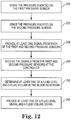
- Figure 11 is an illustration of a method of determining the fluid volume in the blood reservoir system 70 of Figures 6 and 7 and in the blood reservoir system 110 of Figure 8 .
- the differential pressure sensor senses the pressure difference between pressures on the first and second sides of the differential pressure sensor.
- the differential pressure sensor senses the pressure difference between the pressure exerted on the differential pressure sensor by fluid in the blood reservoir and the pressure exerted on the fluid in the blood reservoir.
- the differential pressure sensor provides at least one signal that indicates the fluid level in the blood reservoir.
- a controller receives the at least one signal from the differential pressure sensor and, at 236, the controller determines the fluid volume in the blood reservoir based on the at least one signal. At 238, the controller provides at least one of a fluid level signal that indicates the fluid level in the blood reservoir and a fluid volume signal that indicates the fluid volume in the blood reservoir.
- Figure 12 is an illustration of a method of determining at least one of a fluid level and a fluid volume in the blood reservoir system 150 of Figure 9 and in the blood reservoir system 190 of Figure 10 .
- the first pressure sensor located at the bottom of the blood reservoir and in contact with the volume of fluid senses the hydrostatic pressure exerted on the first pressure sensor by the fluid in the blood reservoir.
- the second pressure sensor senses the pressure exerted on the volume of fluid in the blood reservoir.
- each of the first and second pressure sensors provides at least one electrical signal that indicates or correlates to the pressure sensed by the pressure sensor.
- the controller receives the signals from the first and second pressure sensors and, at 258, the controller determines at least one of a fluid level in the blood reservoir and a fluid volume in the blood reservoir based on the received signals.
- the controller provides at least one of a fluid level signal that indicates the fluid level in the blood reservoir and a fluid volume signal that indicates the fluid volume in the blood reservoir.
Landscapes
- Health & Medical Sciences (AREA)
- Heart & Thoracic Surgery (AREA)
- Vascular Medicine (AREA)
- Life Sciences & Earth Sciences (AREA)
- General Health & Medical Sciences (AREA)
- Anesthesiology (AREA)
- Biomedical Technology (AREA)
- Hematology (AREA)
- Cardiology (AREA)
- Animal Behavior & Ethology (AREA)
- Engineering & Computer Science (AREA)
- Public Health (AREA)
- Veterinary Medicine (AREA)
- Physics & Mathematics (AREA)
- Fluid Mechanics (AREA)
- General Physics & Mathematics (AREA)
- Pulmonology (AREA)
- External Artificial Organs (AREA)
Claims (15)
- Ein System (52; 70; 110; 150; 190), umfassend:ein Blutreservoir (56; 72; 112; 152; 196), welches einen Boden aufweist und ausgebildet ist, Blut aufzunehmen;einen Differentialdrucksensor (58; 76; 116; 156; 196), welcher mit dem Boden des Blutreservoirs gekoppelt ist und ausgebildet ist, einen Druckunterschied zwischen dem vom Blut auf den Differentialdrucksensor ausgeübten Druck und dem auf das Blut im Blutreservoir (56; 72; 112; 152; 196) ausgeübten Druck zu erkennen und um mindestens ein Signal bereitzustellen, welches ein Blutlevel im Blutreservoir (56; 72; 112; 152; 196) anzeigt; undeine Steuerung (60; 78; 118; 160; 200), welche ausgebildet ist, mindestens ein Signal zu empfangen und basierend auf dem mindestens einen Signal ein Blutvolumen im Blutreservoir (56; 72; 112; 152; 196) zu bestimmen, wobei die Steuerung (60; 78; 118; 160; 200) ausgebildet ist, mindestens ein Blutlevelsignal, welches das Blutlevel im Blut-reservoir anzeigt, oder ein Blutvolumensignal, welches das Blutvolumen (80) im Blutreservoir (56; 72; 112; 152; 196) anzeigt, bereitzustellen,dadurch gekennzeichnet, dass der Differentialdrucksensor (58; 76; 116; 156; 196) in den Boden des Blutreservoirs (56; 72; 112; 152; 196) integriert ist.
- Das System (52; 70; 110; 150; 190) nach Anspruch 1, dadurch gekennzeichnet, dass der Differentialdrucksensor (58; 76; 116; 156; 196) eine erste Seite (94; 132), um den vom Blut auf den Differentialdrucksensor ausgeübten Druck zu erkennen, und eine zweite Seite (96; 134) aufweist, welche zur Atmosphäre offen ist, um den atmosphärischen Druck zu erkennen.
- Das System (70) nach Anspruch 1, dadurch gekennzeichnet, dass der Differentialdrucksensor (76) eine erste Seite aufweist, um den vom Blut auf den Differentialdrucksensor ausgeübten Druck zu erkennen, und eine zweite Seite aufweist, welche mit der Oberseite des Blutreservoirs (70) fluidisch verbunden (98) ist, um den auf das Blut im Blutreservoir (70) ausgeübten Druck wahrzunehmen.
- Das System (150; 190) nach Anspruch 1, dadurch gekennzeichnet, dass der Differentialdrucksensor (156; 196) einen ersten Sensor (154; 192) aufweist, um den vom Blut auf den Differentialdrucksensor ausgeübten Druck zu erkennen, und einen zweiten Sensor (156; 194) aufweist, um den auf das Blut im Blutreservoir ausgeübten Druck zu erkennen.
- Das System (52; 70; 110; 150; 190) nach Anspruch 1, dadurch gekennzeichnet, dass mindestens das Blutlevelsignal, welches das Blutlevel im Blutreservoir (56; 72; 112; 152; 192) anzeigt, oder das Blutvolumensignal, welches das Blutvolumen im Blutreservoir (56; 72; 112; 152; 196) anzeigt, ausgebildet sind, um von einer Herz-Lungen-Maschine (54; 12) empfangen zu werden, welche basierend auf dem mindestens einen Blutlevelsignal, welches das Blutlevel im Blutreservoir (56; 72; 112; 152; 196) anzeigt, oder dem Blutvolumensignal, welches das Blutvolumen im Blutreservoir (56; 72; 112; 152; 196) anzeigt, einen Betriebsparameter der Herz-Lungen-Maschine (54; 12) einstellt.
- Das System (52; 70; 110; 150; 190) nach Anspruch 1, dadurch gekennzeichnet, dass mindestens das Blutlevelsignal, welches das Blutlevel im Blut-Reservoir (56; 72; 112; 152; 196) anzeigt, oder das Blutvolumensignal, welches das Blutvolumen im Blutreservoir (56; 72; 112; 152; 196) anzeigt, ausgebildet sind, um von einem Anzeigesystem empfangen zu werden, welches mindestens das Blutlevel im Blutreservoir (56; 72; 112; 152; 196) oder das Blutvolumen im Blutreservoir (56; 72; 112; 152; 196) darstellt.
- Das System (52; 70; 110; 150; 190) nach Anspruch 1, dadurch gekennzeichnet, dass der Differentialdrucksensor (58; 76; 116; 156; 196) austauschbar ist.
- Das System (52; 70; 110; 150; 190) nach Anspruch 1, dadurch gekennzeichnet, dass die Steuerung (60) Teil einer Herz-Lungen-Maschine (54) und eines Autotransfusionssystems (300) ist.
- Das System nach Anspruch 1, dadurch gekennzeichnet, dass die Steuerung (60; 78; 118; 160; 200) Teil eines Anzeigesystems ist.
- Das System aus Anspruch 1, dadurch gekennzeichnet, dass die Steuerung (60; 78; 118; 160; 200) Teil des Differenzsensors ist.
- Ein Sensorsystem (150; 190), umfassend:einen ersten Drucksensor (154; 192), welcher mit einem Blutreservoir (152; 196) gekoppelt, das ausgebildet ist, Blut aufzunehmen, und einen Boden aufweist, wobei der erste Drucksensor (154; 192) mit dem Boden des Blutreservoirs (154; 196) gekoppelt ist und ausgebildet ist, ein erstes Signal bereitzustellen, welches einen hydrostatischen Druck anzeigt, der vom Blut auf den ersten Drucksensor (154; 192) ausgeübt wird;einen zweiten Drucksensor (156; 194), der ausgebildet ist, ein zweites Signal bereitzustellen, welches den auf das Blut im Blutreservoir (154; 196) ausgeübten Druck anzeigt; undeine Steuerung (160; 200), welche ausgebildet ist, basierend auf dem ersten und zweiten Signal mindestens ein Blutlevel im Blutreservoir (154; 196) oder ein Blutvolumen im Blutreservoir (154; 196) zu bestimmen, wobei der erste Drucksensor und der zweite Drucksensor Teil eines Differentialdrucksensors sind,dadurch gekennzeichnet, dass der Differentialdrucksensor (58; 76; 116; 156; 196) in den Boden des Blutreservoirs (56; 72; 112; 152; 196) integriert ist.
- Ein Verfahren, umfassend:Bereitstellen eines Blutreservoirs (72; 112; 152; 196) mit einem Boden;Bereitstellen eines Differentialdrucksensors (76; 116; 156; 196), der in den Boden des Blutreservoirs (72; 112; 152; 196) integriert ist;Erkennen (230; 250) eines Druckunterschiedes zwischen dem vom Blut im Blutreservoir auf den Differentialdrucksensor ausgeübten Druck und dem auf das Blut im Blutreservoir (72; 112; 152; 196) ausgeübten Druck mittels des Differentialdrucksensors (76; 116; 156; 196);Bereitstellen (232; 254) mindestens eines Signals, welches ein Blutlevel im Blutreservoir (72; 112; 152; 196) anzeigt, durch den Differentialdrucksensor (76; 116; 156; 196);Empfangen (234; 256) des mindestens einen Signals an einer Steuerung (78; 118; 160; 200);Bestimmen eines Blutvolumens im Blutreservoir (72; 112; 152; 196) durch die Steuerung (78; 118; 160; 200) basierend auf dem mindestens einen Signal; undBereitstellen mindestens eines Blutlevelsignals, welches das Blutlevel im Blutreservoir (72; 112; 152; 196) anzeigt, oder eines Blutvolumensignals, welches das Blutvolumen im Blutreservoir (72; 112; 152; 196) anzeigt, durch die Steuerung (78; 118; 160; 200).
- Das Verfahren nach Anspruch 12, dadurch gekennzeichnet, dass das Erkennen (230) umfasst:Erkennen des durch das Blut ausgeübten Drucks auf den Differentialdrucksensor (76; 116) auf einer ersten Seite des Differentialdrucksensors (76; 116); undErkennen des atmosphärischen Drucks auf einer zweiten Seite des Differentialsensors (76; 116).
- Das Verfahren nach Anspruch 12, dadurch gekennzeichnet, dass das Erkennen (230) umfasst:Erkennen des durch das Blut ausgeübten Drucks auf den Differentialdrucksensor (76) auf einer ersten Seite des Differentialdrucksensors (76); undErkennen des auf das Blut im Blutreservoir (76) ausgeübten Drucks durch fluidische Kopplung (98) zu der Oberseite des Blut-Reservoirs (76).
- Das Verfahren nach Anspruch 12, dadurch gekennzeichnet, dass das Erkennen (250) umfasst:Erkennen des durch das Blut ausgeübten Drucks auf den Differentialdrucksensor mit einem ersten Sensor (154; 192); undErkennen des auf das Blut im Blutreservoir (152; 196) ausgeübten Drucks mit einem zweiten Sensor (156; 194).
Applications Claiming Priority (1)
| Application Number | Priority Date | Filing Date | Title |
|---|---|---|---|
| PCT/IB2014/061491 WO2015173611A1 (en) | 2014-05-16 | 2014-05-16 | Blood reservoir with fluid volume measurement based on pressure sensor |
Publications (2)
| Publication Number | Publication Date |
|---|---|
| EP3142719A1 EP3142719A1 (de) | 2017-03-22 |
| EP3142719B1 true EP3142719B1 (de) | 2019-11-06 |
Family
ID=50897675
Family Applications (1)
| Application Number | Title | Priority Date | Filing Date |
|---|---|---|---|
| EP14729052.2A Active EP3142719B1 (de) | 2014-05-16 | 2014-05-16 | Blutreservoir mit flüssigkeitsvolumenmessung auf der basis eines drucksensors |
Country Status (3)
| Country | Link |
|---|---|
| US (1) | US10458833B2 (de) |
| EP (1) | EP3142719B1 (de) |
| WO (1) | WO2015173611A1 (de) |
Cited By (1)
| Publication number | Priority date | Publication date | Assignee | Title |
|---|---|---|---|---|
| US11419969B2 (en) | 2019-03-26 | 2022-08-23 | Nuwellis, Inc. | Neonatal and pediatric blood filtration system |
Families Citing this family (16)
| Publication number | Priority date | Publication date | Assignee | Title |
|---|---|---|---|---|
| DE102009026592B4 (de) | 2009-05-29 | 2014-08-28 | Sorin Group Deutschland Gmbh | Vorrichtung zur Festlegung des venösen Zuflusses zu einem Blutreservoir eines extrakorporalen Blutkreislaufs |
| EP2754458B1 (de) | 2011-07-12 | 2017-02-01 | Sorin Group Italia S.r.l. | Doppelkammer-blutreservoir |
| US10690684B2 (en) | 2013-05-10 | 2020-06-23 | Majelco Medical, Inc. | Apparatus and system for measuring volume of blood loss |
| JP7054380B2 (ja) * | 2016-03-23 | 2022-04-13 | テルモ株式会社 | 体外循環管理装置、体外循環装置、体外循環管理システム、体外循環管理プログラム及び体外循環管理装置の作動方法 |
| WO2017180656A1 (en) * | 2016-04-11 | 2017-10-19 | Alfred Akerman | Apparatus and system for measuring volume of blood loss |
| CN105928587A (zh) * | 2016-06-25 | 2016-09-07 | 苏州赛智达智能科技有限公司 | 高精度数字液位计 |
| JP6890817B2 (ja) * | 2016-12-15 | 2021-06-18 | 泉工医科工業株式会社 | 血液循環システム |
| US11550345B2 (en) * | 2018-10-17 | 2023-01-10 | Pneuma Systems Corporation | Airflow-based volumetric pump |
| US11215492B2 (en) * | 2018-11-26 | 2022-01-04 | Analysis And Measurement Services Corporation | Differential pressure based level measurement systems and methods |
| US10914617B1 (en) * | 2019-07-29 | 2021-02-09 | Terumo Cardiovascular Systems Corporation | Flexible sensor mount for hard shell blood reservoir |
| US20230109668A9 (en) * | 2019-11-08 | 2023-04-06 | Bio Health Frontiers, Inc. | Differential Pressure Fluid Delivery System |
| WO2021154824A1 (en) * | 2020-01-29 | 2021-08-05 | Baxter International Inc. | Dialysis system and apparatus with fluid flow control |
| WO2021216730A2 (en) * | 2020-04-22 | 2021-10-28 | Nxstage Medical, Inc. | Flow balancing devices, methods, and systems |
| CN117098568A (zh) * | 2021-03-26 | 2023-11-21 | 株式会社Jms | 血液循环回路 |
| US11935389B2 (en) | 2022-08-10 | 2024-03-19 | Honeywell International Inc. | Methods and apparatuses for monitoring intravenous fluid bags |
| US20250222181A1 (en) * | 2024-01-08 | 2025-07-10 | Imperative Care, Inc. | Methods for blood capture and reintroduction during aspiration procedure |
Citations (1)
| Publication number | Priority date | Publication date | Assignee | Title |
|---|---|---|---|---|
| WO2007018513A1 (en) * | 2005-07-28 | 2007-02-15 | William James Van Ee | Liquid level sensing system with liquid identification capability |
Family Cites Families (203)
| Publication number | Priority date | Publication date | Assignee | Title |
|---|---|---|---|---|
| NL6811762A (de) | 1968-08-17 | 1970-02-19 | ||
| US3551072A (en) | 1969-01-31 | 1970-12-29 | Ladish Co | Variable speed motor driven pumping system |
| US3588859A (en) | 1969-04-21 | 1971-06-28 | Frank Petree | Level detector |
| US3927980A (en) | 1973-08-22 | 1975-12-23 | Baxter Laboratories Inc | Oxygen overpressure protection system for membrane-type blood oxygenators |
| US3851181A (en) | 1973-11-07 | 1974-11-26 | Audronics Inc | Blood level detector |
| DE2455229A1 (de) | 1974-11-21 | 1976-05-26 | Stoeckert Instr Apparatebau Gm | Herzlungenmaschine und insbesondere partielle bypass-maschine |
| US4170765A (en) | 1975-04-17 | 1979-10-09 | Marvtek, Corporation | Liquid level sensor |
| US4006745A (en) | 1975-05-22 | 1977-02-08 | Sorenson Research Co., Inc. | Autologous transfusion system and method |
| US4309871A (en) | 1977-11-01 | 1982-01-12 | Borg-Warner Corporation | Control apparatus for controlling surge in air compressor-driven system |
| US4177649A (en) | 1977-11-01 | 1979-12-11 | Borg-Warner Corporation | Surge suppression apparatus for compressor-driven system |
| DE2754894C2 (de) | 1977-12-09 | 1983-10-13 | Fresenius AG, 6380 Bad Homburg | Vorrichtung zum Bilanzieren einer einem Patienten entnommenen Flüssigkeit mit einer Ersatzflüssigkeit |
| US4193004A (en) | 1978-06-22 | 1980-03-11 | Cobe Laboratories, Inc. | Fluid level monitoring through fluid cell protrusion |
| JPS5623960A (en) | 1979-08-03 | 1981-03-06 | Nippon Medical Sapurai Kk | Artificial lung |
| WO1981002836A1 (en) | 1980-03-03 | 1981-10-15 | Gambro Ab | A device for the transfer of one or more substances between a gas and a liquid |
| US4466804A (en) | 1981-09-25 | 1984-08-21 | Tsunekazu Hino | Extracorporeal circulation of blood |
| US4448207A (en) | 1981-11-03 | 1984-05-15 | Vital Metrics, Inc. | Medical fluid measuring system |
| US4490331A (en) | 1982-02-12 | 1984-12-25 | Steg Jr Robert F | Extracorporeal blood processing system |
| US4599093A (en) | 1982-02-12 | 1986-07-08 | Steg Jr Robert F | Extracorporeal blood processing system |
| US4464164A (en) | 1982-09-24 | 1984-08-07 | Extracorporeal Medical Specialties, Inc. | Flowrate control for a blood flow system |
| US4530696A (en) * | 1983-06-13 | 1985-07-23 | Institute Of Critical Care Medicine | Monitor for intravenous injection system for detecting occlusion and/or infiltration |
| US4518318A (en) | 1983-07-07 | 1985-05-21 | Grundfos A/S | Pumping sets |
| US4678404A (en) | 1983-10-28 | 1987-07-07 | Hughes Tool Company | Low volume variable rpm submersible well pump |
| DE3485551D1 (de) | 1983-11-11 | 1992-04-09 | Terumo Corp | Einrichtung zum aufnehmen und behandeln von blut. |
| US4701101A (en) | 1984-03-13 | 1987-10-20 | Catalyst Technology, Inc. | Modular multi-tube catalyst loading funnel |
| US4602344A (en) * | 1984-10-25 | 1986-07-22 | Air Products And Chemicals, Inc. | Method and system for measurement of liquid level in a tank |
| US4782451A (en) * | 1984-11-30 | 1988-11-01 | Union Carbide Corporation | Process for maintaining liquid supply |
| US4642089A (en) | 1985-01-29 | 1987-02-10 | Shiley, Inc. | Unitary venous return reservoir with cardiotomy filter |
| JPS61276562A (ja) | 1985-05-31 | 1986-12-06 | テルモ株式会社 | 貯血槽 |
| US4828543A (en) | 1986-04-03 | 1989-05-09 | Weiss Paul I | Extracorporeal circulation apparatus |
| JPS62258671A (ja) | 1986-05-01 | 1987-11-11 | テルモ株式会社 | 貯血槽 |
| US4876066A (en) | 1986-07-14 | 1989-10-24 | Baxter International Inc. | Integrated membrane oxygenator, heat exchanger and reservoir |
| US5110549A (en) | 1986-07-14 | 1992-05-05 | Baxter International Inc. | Liquid and gas separation system |
| BE905615R (nl) | 1986-09-10 | 1987-04-17 | Hombrouckx Remi O J | Methode en apparatuur voor eennaaldhemodialyse. |
| JPS6411560A (en) | 1987-07-07 | 1989-01-17 | Terumo Corp | Blood storage tank |
| US5078677A (en) | 1987-09-29 | 1992-01-07 | Conmed Corporation | Apparatus for collecting blood from a chest drainage unit and reinfusion of the blood |
| US4846800A (en) | 1987-10-14 | 1989-07-11 | Kenneth Ouriel | Two chambered autotransfuser device and method of use |
| IT1223470B (it) | 1987-12-15 | 1990-09-19 | Dideco Spa | Unita' integrata in circuito extracorporeo di sangue |
| DE3805269A1 (de) | 1988-02-19 | 1989-08-31 | Gruenzweig & Hartmann | Daemmatte fuer koerper mit wenigstens bereichsweise gekruemmter oberflaeche, insbesondere fuer rohre, sowie ihre verwendung |
| DE3828441A1 (de) | 1988-08-22 | 1990-03-15 | Heinze Werner | Fuellstandmessgeraet fuer blutreservoire, insbesondere von humanmedizinischen geraeten |
| US4955874A (en) | 1988-09-27 | 1990-09-11 | Pfizer Hospital Products Group, Inc. | Drainage device |
| EP0371173A1 (de) | 1988-11-03 | 1990-06-06 | BAXTER INTERNATIONAL INC. (a Delaware corporation) | Integrale Vorrichtung zum Entschäumen, Sammeln und Erwärmen von Blut sowie zum Filtern eines Kardiotomiestromes |
| US5226265A (en) | 1989-03-22 | 1993-07-13 | The Burke Company | Apparatus and method for lifting tilt-up wall constructions |
| US4984462A (en) | 1989-05-30 | 1991-01-15 | Meditor Corporation | Detachable liquid level monitoring apparatus and method |
| US5049146A (en) | 1989-05-31 | 1991-09-17 | Baxter International, Inc. | Blood/gas separator and flow system |
| JPH0344516A (ja) * | 1989-07-13 | 1991-02-26 | Nippon Oil Co Ltd | 液面検出装置 |
| US4991433A (en) | 1989-09-21 | 1991-02-12 | Applied Acoustic Research | Phase track system for monitoring fluid material within a container |
| US5186431A (en) | 1989-09-22 | 1993-02-16 | Yehuda Tamari | Pressure sensitive valves for extracorporeal circuits |
| DE3935502C2 (de) | 1989-10-25 | 1995-04-13 | Heimes Horst Peter Dr Ing | Gekapselte Flüssigkeitspumpe |
| US5039430A (en) | 1989-11-20 | 1991-08-13 | Medtronic, Inc. | Method and apparatus for combining cardiotomy and venous blood |
| JPH0628134Y2 (ja) | 1990-01-05 | 1994-08-03 | 泉工医科工業株式会社 | 血液リザーバの液面レベル調節装置 |
| US5215519A (en) | 1990-03-07 | 1993-06-01 | Shettigar U Ramakrishna | Autotransfusion membrane system with means for providing reverse filtration |
| US5055198A (en) | 1990-03-07 | 1991-10-08 | Shettigar U Ramakrishna | Autologous blood recovery membrane system and method |
| US5149318A (en) | 1990-03-14 | 1992-09-22 | Minnesota Mining And Manufacturing Company | Quick-changeover blood handling apparatus |
| DE69111664T2 (de) | 1990-04-16 | 1996-04-04 | Nikkiso Co Ltd | Blutpumpe und Apparat für die extracorporale Blutzirkulation. |
| US5061236A (en) | 1990-07-16 | 1991-10-29 | Baxter International Inc. | Venous reservoir with improved inlet configuration and integral screen for bubble removal |
| US5178603A (en) | 1990-07-24 | 1993-01-12 | Baxter International, Inc. | Blood extraction and reinfusion flow control system and method |
| US5227049A (en) | 1990-08-20 | 1993-07-13 | Hospal Industrie | Single-needle circuit for circulating blood outside the body in blood treatment apparatus |
| US5270005A (en) | 1990-09-07 | 1993-12-14 | Baxter International Inc. | Extracorporeal blood oxygenation system incorporating integrated reservoir-membrane oxygenerator-heat exchanger and pump assembly |
| CN1052916C (zh) | 1990-11-30 | 2000-05-31 | 黎浩钧 | 医用软性器件及其控制弯曲度的方法和装置 |
| US5135485A (en) * | 1991-02-25 | 1992-08-04 | Louis Cohen | Capacitance-type fluid level sensor for i.v. and catheter bags |
| US5158533A (en) | 1991-03-26 | 1992-10-27 | Gish Biomedical, Inc. | Combined cardiotomy/venous/pleural drainage autotransfusion unit with filter and integral manometer and water seal |
| US5240380A (en) | 1991-05-21 | 1993-08-31 | Sundstrand Corporation | Variable speed control for centrifugal pumps |
| US5318510A (en) | 1991-06-11 | 1994-06-07 | Deknatel Technology Corporation, Inc. | Collection device |
| US5303585A (en) | 1991-10-31 | 1994-04-19 | Jtl Medical Corporation | Fluid volume sensor |
| US5586085A (en) * | 1991-10-31 | 1996-12-17 | Lichte; Leo J. | Container and adaptor for use with fluid volume sensor |
| US5403273A (en) | 1991-12-17 | 1995-04-04 | Minnesota Mining And Manufacturing Company | Blood reservoir |
| US5282783A (en) | 1991-12-17 | 1994-02-01 | Minnesota Mining And Manufacturing Company | Blood reservoir |
| US5458579A (en) | 1991-12-31 | 1995-10-17 | Technalytics, Inc. | Mechanical trocar insertion apparatus |
| US5399074A (en) | 1992-09-04 | 1995-03-21 | Kyocera Corporation | Motor driven sealless blood pump |
| US5458566A (en) | 1993-03-24 | 1995-10-17 | Haemonetics, Inc. | Reservoir volume sensing systems for autologous blood recovery |
| KR100344716B1 (ko) | 1993-09-20 | 2002-11-23 | 가부시키 가이샤 에바라 세이사꾸쇼 | 펌프의운전제어장치 |
| US5591399A (en) * | 1993-10-14 | 1997-01-07 | Goldman; Julian M. | System for diagnosing oxygenator failure |
| US5563584A (en) * | 1993-11-15 | 1996-10-08 | The Johns Hopkins University | Liquid level sensing and monitoring system for medical fluid infusion systems |
| US5411705A (en) | 1994-01-14 | 1995-05-02 | Avecor Cardiovascular Inc. | Combined cardiotomy and venous blood reservoir |
| JPH0819602A (ja) | 1994-07-05 | 1996-01-23 | Senko Ika Kogyo Kk | 血液リザーバ |
| US6514419B2 (en) | 1994-09-16 | 2003-02-04 | Transonic Systems, Inc. | Method to measure blood flow and recirculation in hemodialysis shunts |
| US5604315A (en) * | 1995-01-12 | 1997-02-18 | Setra Systems, Inc. | Apparatus using a feedback network to measure fluid pressures |
| US5823986A (en) | 1995-02-08 | 1998-10-20 | Medtronic, Inc. | Perfusion system |
| FR2730767B1 (fr) | 1995-02-21 | 1997-04-18 | Inst Francais Du Petrole | Procede et dispositif de regulation d'un ensemble de pompage polyphasique |
| US5725357A (en) | 1995-04-03 | 1998-03-10 | Ntn Corporation | Magnetically suspended type pump |
| US6652495B1 (en) | 1995-04-10 | 2003-11-25 | Kenneth Gordon Walker | System for disposal of fluids |
| US5667485A (en) | 1995-05-01 | 1997-09-16 | Minnesota Mining And Manufacturing Company | Blood reservoir with visible inlet tube |
| WO1999015212A1 (en) | 1997-09-24 | 1999-04-01 | The Cleveland Clinic Foundation | Flow controlled blood pump system |
| EP0766974B1 (de) | 1995-10-03 | 2006-09-06 | Terumo Kabushiki Kaisha | Blutbehälter, sowie Instrument und Gerät zur Abgabe von Blut |
| US6123519A (en) | 1995-10-03 | 2000-09-26 | Terumo Kabushiki Kaisha | Delivery blood storing member-equipped blood reservoir tank and blood delivery instrument for extracorporeal circulation circuit |
| CN1147964A (zh) | 1995-10-17 | 1997-04-23 | 郭伟 | 组合电极导管 |
| US5770073A (en) | 1996-03-15 | 1998-06-23 | Minntech Corporation | Combined cardiotomy and venous reservoir |
| IT1283482B1 (it) | 1996-07-22 | 1998-04-21 | Dideco Spa | Dispositivo combinato comprendente serbatoio di sangue venoso e cardiotomo in circuito extracorporeo |
| US5826576A (en) | 1996-08-08 | 1998-10-27 | Medtronic, Inc. | Electrophysiology catheter with multifunction wire and method for making |
| US5800721A (en) | 1996-08-30 | 1998-09-01 | Baxter International Inc. | Combined cardiotomy fluid and venous blood reservoir |
| US5813972A (en) | 1996-09-30 | 1998-09-29 | Minnesota Mining And Manufacturing Company | Medical perfusion system with data communications network |
| US5849186A (en) | 1996-11-15 | 1998-12-15 | C. R. Bard Inc. | Integrated cardiotomy and venous blood reservoir |
| US5928180A (en) | 1997-03-25 | 1999-07-27 | Krivitski; Nikolai M. | Method and apparatus for real time monitoring of blood volume in a filter |
| US5823045A (en) | 1997-04-29 | 1998-10-20 | Medtronic, Inc. | Measuring blood volume in soft-shell venous resevoirs by displacement |
| EP1011751A1 (de) | 1997-04-29 | 2000-06-28 | Medtronic Inc. | Ultraschallmessung des blutvolumens in weichschaligen behältern für venöses blut |
| US5756940C1 (en) | 1997-04-29 | 2002-07-02 | Medtronic Inc | Weight measurement of blood volume soft-shell venous reservoirs |
| US5955672A (en) | 1997-04-29 | 1999-09-21 | Medtronic, Inc. | Ultrasonic blood volume measurement in soft-shell venous reservoir |
| US6048363A (en) | 1997-05-13 | 2000-04-11 | Nagyszalanczy; Lorant | Centrifugal blood pump apparatus |
| FR2765205B1 (fr) * | 1997-06-26 | 1999-08-06 | Air Liquide | Dispositif de surveillance du niveau de stockage d'un produit stocke dans un reservoir |
| CA2299506C (en) | 1997-08-15 | 2007-07-31 | Baxter International Inc. | System and method for minimally invasive surgery with vacuum-assisted venous drainage |
| US6017493A (en) | 1997-09-26 | 2000-01-25 | Baxter International Inc. | Vacuum-assisted venous drainage reservoir for CPB systems |
| JP3919896B2 (ja) | 1997-09-05 | 2007-05-30 | テルモ株式会社 | 遠心式液体ポンプ装置 |
| DE19755056A1 (de) * | 1997-12-11 | 1999-06-17 | Bosch Gmbh Robert | Füllstandsmeßvorrichtung für einen Kraftstoffbehälter eines Kraftfahrzeugs |
| CN1121242C (zh) | 1998-01-12 | 2003-09-17 | 周国明 | 人工肺底置式血液平面浓度动态监测系统 |
| US6804543B2 (en) | 1998-02-05 | 2004-10-12 | Hema Metrics, Inc. | Sensor for transcutaneous measurement of vascular access blood flow |
| JP4051812B2 (ja) | 1998-04-13 | 2008-02-27 | 株式会社ジェイ・エム・エス | 制御機能を備えた体外循環装置 |
| DE19817995C1 (de) | 1998-04-22 | 1999-09-09 | Stoeckert Instr Gmbh | Vorrichtung zur Überwachung des Füllstands eines Blutreservoirs |
| WO1999064667A1 (en) | 1998-06-11 | 1999-12-16 | Sulzer Pumpen Ag | Control system for a vacuum pump used for removing liquid and a method of controlling said pump |
| WO1999065413A1 (de) | 1998-06-13 | 1999-12-23 | Pfefferkorn & Co. Gmbh | Druckkörper zum ausüben eines drucks auf eine fläche |
| US6337049B1 (en) | 1998-08-28 | 2002-01-08 | Yehuda Tamari | Soft shell venous reservoir |
| DE19841611B4 (de) | 1998-09-11 | 2004-12-02 | Argomedical Ag | Implantierbare Prothese mit zumindest zwei gegeneinander verstellbaren Abschnitten sowie Verwendung verstellbarer Abschnitte |
| US6146411A (en) * | 1998-12-24 | 2000-11-14 | Alsius Corporation | Cooling system for indwelling heat exchange catheter |
| DK199900119A (da) | 1999-01-29 | 2000-09-04 | Polystan Holding As | Trykregulator til vakuumassisteret drænage |
| AUPP995999A0 (en) | 1999-04-23 | 1999-05-20 | University Of Technology, Sydney | Non-contact estimation and control system |
| EP1053760A3 (de) | 1999-05-21 | 2001-08-16 | Medtronic, Inc. | Weichwandiger Behälter |
| EP1070509A3 (de) | 1999-07-23 | 2002-04-24 | Medtronic, Inc. | Sicherheitsvorrichtung zur vakuumunterstützten venösen Drainage |
| US7933780B2 (en) * | 1999-10-22 | 2011-04-26 | Telaric, Llc | Method and apparatus for controlling an infusion pump or the like |
| US7225809B1 (en) | 1999-11-01 | 2007-06-05 | Ric Investments, Llc | Method and apparatus for monitoring and controlling a medical device |
| FR2802799B1 (fr) | 1999-12-23 | 2002-08-16 | Depuy France | Ensemble de prothese d'epaule |
| US6347633B1 (en) | 2000-01-14 | 2002-02-19 | First Circle Medical, Inc. | Treatment of hepatitis C using hyperthermia |
| JP4332969B2 (ja) | 2000-01-31 | 2009-09-16 | 株式会社ジェイ・エム・エス | 貯血槽 |
| CA2370758A1 (en) | 2000-03-01 | 2001-09-07 | Gambro, Inc. | Extracorporeal blood processing information management system |
| CZ305727B6 (cs) | 2000-03-27 | 2016-02-24 | The Cleveland Clinic Foundation | Pomocný přístroj pro pacienty s onemocněním srdce a způsob řízení průtoku krve krevní pumpou |
| AU2001251489A1 (en) | 2000-04-06 | 2001-10-23 | Cobe Cardiovascular, Inc. | Assembly for extracorporeal blood handling and method of use |
| SE515604C2 (sv) * | 2000-04-28 | 2001-09-10 | Bst Ab | Förfarande och anordning för uppsugning och transport av vätskor, företrädesvis blod |
| FR2811752B1 (fr) * | 2000-07-13 | 2002-10-18 | Profroid | Procede et dispositif de mesure du volume d'un liquide |
| US6542848B1 (en) * | 2000-07-31 | 2003-04-01 | Chart Inc. | Differential pressure gauge for cryogenic fluids |
| US20080027368A1 (en) | 2000-09-27 | 2008-01-31 | Sorin Group Usa, Inc. | Disposable cartridge for a blood perfusion system |
| WO2002026286A2 (en) * | 2000-09-27 | 2002-04-04 | Cobe Cardiovascular, Inc. | Blood perfusion system |
| US6585675B1 (en) | 2000-11-02 | 2003-07-01 | Chf Solutions, Inc. | Method and apparatus for blood withdrawal and infusion using a pressure controller |
| ATE265832T1 (de) | 2000-11-16 | 2004-05-15 | Willi Horber | Endoprothese für ein schultergelenk |
| JP2004512922A (ja) | 2000-11-16 | 2004-04-30 | ホーバー,ウィリー | 人工関節 |
| US6562012B1 (en) * | 2000-11-20 | 2003-05-13 | Alaris Medical Systems, Inc. | Apparatus and method for measuring drop size in an intravenous drip chamber |
| DE60126558T2 (de) | 2000-11-30 | 2007-11-22 | Terumo K.K. | Blutreservoir |
| JP2002165878A (ja) | 2000-11-30 | 2002-06-11 | Terumo Corp | 貯血槽 |
| US6808503B2 (en) | 2001-03-06 | 2004-10-26 | Baxter International Inc. | Automated system and method for pre-surgical blood donation and fluid replacement |
| JP2002336348A (ja) | 2001-05-15 | 2002-11-26 | Terumo Corp | レベルセンサー用固定具および該固定具を取付けた人工心肺の静脈血リザーバ |
| JP4590161B2 (ja) | 2001-05-21 | 2010-12-01 | スコット・ラボラトリーズ・インコーポレイテッド | 医療容器のためのrf−idラベル |
| US6606905B2 (en) * | 2001-08-15 | 2003-08-19 | Northrop Grumman Corporation | Liquid level and weight sensor |
| EP1284369A1 (de) | 2001-08-16 | 2003-02-19 | Levitronix LLC | Verfahren und Pumpvorrichtung zum Erzeugen eines einstellbaren, im wesentlichen konstanten Volumenstroms |
| US6623420B2 (en) | 2001-08-16 | 2003-09-23 | Apex Medical, Inc. | Physiological heart pump control |
| JP2003052717A (ja) | 2001-08-21 | 2003-02-25 | Olympus Optical Co Ltd | 医療機器システム装置 |
| US6631639B1 (en) * | 2001-09-07 | 2003-10-14 | Cosense, Inc | System and method of non-invasive discreet, continuous and multi-point level liquid sensing using flexural waves |
| JP2005503870A (ja) | 2001-09-27 | 2005-02-10 | ガンブロ、 インコーポレイテッド | 体外血液処理に使用する高周波または電磁気情報装置および方法 |
| JP4132777B2 (ja) | 2001-10-25 | 2008-08-13 | 川澄化学工業株式会社 | 人工肺の貯血槽 |
| US6564627B1 (en) | 2002-01-17 | 2003-05-20 | Itt Manufacturing Enterprises, Inc. | Determining centrifugal pump suction conditions using non-traditional method |
| US6694570B2 (en) | 2002-03-11 | 2004-02-24 | Compal Electronics, Inc. | Hinge device |
| ITMI20020526A1 (it) | 2002-03-12 | 2003-09-12 | Dideco Spa | Serbatoio di sangue venoso in circuito extracorporeo |
| US7284956B2 (en) | 2002-09-10 | 2007-10-23 | Miwatec Co., Ltd. | Methods and apparatus for controlling a continuous flow rotary blood pump |
| US20040062658A1 (en) | 2002-09-27 | 2004-04-01 | Beck Thomas L. | Control system for progressing cavity pumps |
| ATE472355T1 (de) | 2002-12-03 | 2010-07-15 | Toagosei Co Ltd | Verfahren zur herstellung eines dichtungsteils auf einem filtrationselement |
| AU2003903138A0 (en) | 2003-06-20 | 2003-07-03 | Resmed Limited | Method and apparatus for improving the comfort of cpap |
| JP2005066013A (ja) | 2003-08-25 | 2005-03-17 | Miwatec:Kk | 定常流ロータリ血液ポンプ制御のための方法及び装置 |
| US7364563B2 (en) * | 2003-10-02 | 2008-04-29 | Minnetronix, Inc. | Continuous volume detection for a flexible venous reservoir in a cardiopulmonary bypass circuit |
| WO2006057650A2 (en) | 2004-01-22 | 2006-06-01 | Yehuda Tamari | A colsed venous -cardiotomy reservoir with improved air handling |
| US6931926B1 (en) * | 2004-04-16 | 2005-08-23 | William J. Van Ee | Liquid depth sensing system with liquid identification capability |
| JP2006025531A (ja) | 2004-07-07 | 2006-01-26 | Seiko Instruments Inc | Dc−dcコンバータ回路 |
| DE102004040441A1 (de) | 2004-08-20 | 2006-06-14 | Disetronic Licensing Ag | Vorrichtung und Verfahren zur Bestimmung des Füllstandes einer Ampulle |
| US7519432B2 (en) | 2004-10-21 | 2009-04-14 | Medtronic, Inc. | Implantable medical lead with helical reinforcement |
| US7430032B2 (en) | 2004-10-29 | 2008-09-30 | Lg Display Co., Ltd. | Multi-domain liquid crystal display device and fabrication method with central and peripheral control electrodes formed on same layer and plurality of field distortion slits formed in pixel electrode |
| DE102005001779B4 (de) | 2005-01-14 | 2009-12-17 | Fresenius Medical Care Deutschland Gmbh | Disposable zum Betreiben einer Blutbehandlungsvorrichtung im Einnadel- oder Zweinadel-Betrieb |
| US20060226087A1 (en) | 2005-04-08 | 2006-10-12 | Mission Medical, Inc. | Method and apparatus for blood separations |
| EP1883792A4 (de) * | 2005-05-11 | 2009-07-08 | Innovative Solutions & Support | System und verfahren zur überwachung der flugzeugtreibstoffkapazität auf druckbasis |
| ATE479843T1 (de) | 2005-05-18 | 2010-09-15 | Gambro Lundia Ab | Vorrichtung zur steuerung des blutflusses in einem extrakorporalen kreislauf |
| JP2006325750A (ja) | 2005-05-24 | 2006-12-07 | Senko Medical Instr Mfg Co Ltd | 血液循環システム及びその制御装置 |
| US8231749B2 (en) | 2005-06-02 | 2012-07-31 | Automed Technologies, Inc. | Apparatus and methods for dispensing pre-filled containers with precisely-applied patient-specific information |
| DE102005029682A1 (de) | 2005-06-21 | 2006-12-28 | Maquet Cardiopulmonary Ag | Extrakorporales Zirkulationssystem, insbesondere für einen multifunktionalen Herz-Lungen-Bypass und zur Minimierung von Luftembolien |
| RU2293176C1 (ru) | 2005-09-02 | 2007-02-10 | Николай Петрович Кузьмичев | Способ кратковременной эксплуатации скважины погружной насосной установкой с электроприводом (способ кузьмичева) |
| US20070142923A1 (en) | 2005-11-04 | 2007-06-21 | Ayre Peter J | Control systems for rotary blood pumps |
| JP4500764B2 (ja) | 2005-11-11 | 2010-07-14 | テルモ株式会社 | 体外循環装置 |
| US7342531B2 (en) | 2006-02-21 | 2008-03-11 | Rosemount Tank Radar Ab | Redundant level measurement in radar level gauging system |
| EP2026856B1 (de) | 2006-05-31 | 2015-08-26 | VADovations, Inc. | Herzunterstützungsvorrichtung |
| US20080078382A1 (en) | 2006-09-20 | 2008-04-03 | Lemahieu Edward | Methods and Systems of Delivering Medication Via Inhalation |
| US8187214B2 (en) | 2006-10-30 | 2012-05-29 | Lifebridge Medizintechnik Ag | Apparatus for making extracorporeal blood circulation available |
| JP4867692B2 (ja) | 2007-02-15 | 2012-02-01 | 株式会社ジェイ・エム・エス | カーディオトミーフィルタ及び貯血槽 |
| US8409124B2 (en) | 2007-03-08 | 2013-04-02 | Medronic, Inc. | Blood pump system user interface alarm management |
| US7694570B1 (en) * | 2007-03-30 | 2010-04-13 | Cosense, Inc | Non-invasive dry coupled disposable/reusable ultrasonic sensor |
| GB0706382D0 (en) | 2007-04-02 | 2007-05-09 | Huntleigh Technology Plc | Fluid level sensor |
| JP2008270595A (ja) | 2007-04-23 | 2008-11-06 | Texas Instr Japan Ltd | 反応生成物剥離防止構造及びその製作方法、並びに当該構造を用いる半導体装置の製造方法 |
| DE102007026010B4 (de) | 2007-06-04 | 2010-11-25 | Fresenius Medical Care Deutschland Gmbh | Vorrichtung zur Steuerung einer Einrichtung zum Fördern von Blut und Verfahren zum Fördern von Blut in einer Blutleitung eines extrakorporalen Blutkreislaufs einer extrakorporalen Blutbehandlungsvorrichtung |
| ES2376666T3 (es) * | 2007-10-04 | 2012-03-15 | Gambro Lundia Ab | Aparato de infusión. |
| US8105265B2 (en) * | 2007-10-12 | 2012-01-31 | Deka Products Limited Partnership | Systems, devices and methods for cardiopulmonary treatment and procedures |
| JP4830064B2 (ja) | 2008-03-28 | 2011-12-07 | 静岡県 | 点滴計測システム |
| AU2008357106B2 (en) | 2008-05-26 | 2013-02-07 | Gambro Lundia Ab | A hemodialysis or hemo(dia)filtration apparatus and a method for controlling a hemodialysis or hemo(dia)filtration apparatus |
| ITMO20080159A1 (it) * | 2008-05-27 | 2009-11-28 | Gambro Lundia Ab | Circuito fluido medicale. |
| JP5083622B2 (ja) | 2008-05-27 | 2012-11-28 | 株式会社ジェイテクト | 円錐ころ軸受 |
| US8202240B2 (en) | 2008-08-12 | 2012-06-19 | Caridianbct, Inc. | System and method for collecting plasma protein fractions from separated blood components |
| CN102176935B (zh) | 2008-10-09 | 2014-08-06 | 尼普洛株式会社 | 储血槽 |
| US8177072B2 (en) | 2008-12-04 | 2012-05-15 | Thermogenesis Corp. | Apparatus and method for separating and isolating components of a biological fluid |
| US7982612B2 (en) * | 2009-02-20 | 2011-07-19 | Mckesson Automation Inc. | Methods, apparatuses, and computer program products for monitoring a volume of fluid in a flexible fluid bag |
| ATE519881T1 (de) | 2009-05-04 | 2011-08-15 | Coprecitec Sl | Haushaltswasch- oder spülmaschine und steuerung hierfür |
| DE102009026592B4 (de) | 2009-05-29 | 2014-08-28 | Sorin Group Deutschland Gmbh | Vorrichtung zur Festlegung des venösen Zuflusses zu einem Blutreservoir eines extrakorporalen Blutkreislaufs |
| JP2011076394A (ja) | 2009-09-30 | 2011-04-14 | Seiko Epson Corp | 印刷装置、印刷プログラムおよび印刷方法 |
| US8500673B2 (en) | 2010-04-20 | 2013-08-06 | Sorin Group Italia S.R.L. | Blood reservoir with level sensor |
| US8506513B2 (en) | 2010-04-20 | 2013-08-13 | Sorin Group Italia S.R.L. | Blood reservoir with ultrasonic volume sensor |
| US8734376B2 (en) | 2010-04-20 | 2014-05-27 | Sorin Group Italia S.R.L. | Perfusion system with RFID |
| US8464590B2 (en) * | 2010-09-17 | 2013-06-18 | Cameron International Corporation | Pressure sensor configuration for pressurized tank |
| EP2465553A1 (de) * | 2010-12-14 | 2012-06-20 | B. Braun Avitum AG | Extrakorporale Blutbehandlungsvorrichtung |
| US9283321B2 (en) * | 2011-03-04 | 2016-03-15 | Becton, Dickinson And Company | Smart medication waste disposal |
| EP2754458B1 (de) | 2011-07-12 | 2017-02-01 | Sorin Group Italia S.r.l. | Doppelkammer-blutreservoir |
| US9814828B2 (en) * | 2013-03-15 | 2017-11-14 | Aesynt Incorporated | Method and apparatus for preparing and monitoring an intravenous fluid bag |
| US11988539B2 (en) * | 2013-10-09 | 2024-05-21 | Parker-Hannifin Corporation | Aircraft fluid gauging techniques using pressure measurements and optical sensors |
| US9533135B2 (en) * | 2014-06-19 | 2017-01-03 | Fenwal, Inc. | Method for forming, opening and/or evaluating a connection site |
-
2014
- 2014-05-16 EP EP14729052.2A patent/EP3142719B1/de active Active
- 2014-05-16 US US15/311,495 patent/US10458833B2/en active Active
- 2014-05-16 WO PCT/IB2014/061491 patent/WO2015173611A1/en not_active Ceased
Patent Citations (1)
| Publication number | Priority date | Publication date | Assignee | Title |
|---|---|---|---|---|
| WO2007018513A1 (en) * | 2005-07-28 | 2007-02-15 | William James Van Ee | Liquid level sensing system with liquid identification capability |
Cited By (1)
| Publication number | Priority date | Publication date | Assignee | Title |
|---|---|---|---|---|
| US11419969B2 (en) | 2019-03-26 | 2022-08-23 | Nuwellis, Inc. | Neonatal and pediatric blood filtration system |
Also Published As
| Publication number | Publication date |
|---|---|
| WO2015173611A1 (en) | 2015-11-19 |
| US20170089746A1 (en) | 2017-03-30 |
| EP3142719A1 (de) | 2017-03-22 |
| US10458833B2 (en) | 2019-10-29 |
Similar Documents
| Publication | Publication Date | Title |
|---|---|---|
| US10458833B2 (en) | Blood reservoir with fluid volume measurement based on pressure sensor | |
| US8500673B2 (en) | Blood reservoir with level sensor | |
| US8734376B2 (en) | Perfusion system with RFID | |
| EP2380611B1 (de) | Blutreservoir mit Füllstandsmesser | |
| CN102858387B (zh) | 具有rfid的灌注系统 | |
| US8506513B2 (en) | Blood reservoir with ultrasonic volume sensor | |
| CN104640582B (zh) | 带有rfid特征激活的灌注系统 | |
| EP1713383B1 (de) | Druckmessung | |
| WO2002030267A2 (en) | Devices and methods for body fluid flow control in extracorporeal fluid treatments |
Legal Events
| Date | Code | Title | Description |
|---|---|---|---|
| STAA | Information on the status of an ep patent application or granted ep patent |
Free format text: STATUS: THE INTERNATIONAL PUBLICATION HAS BEEN MADE |
|
| PUAI | Public reference made under article 153(3) epc to a published international application that has entered the european phase |
Free format text: ORIGINAL CODE: 0009012 |
|
| STAA | Information on the status of an ep patent application or granted ep patent |
Free format text: STATUS: REQUEST FOR EXAMINATION WAS MADE |
|
| 17P | Request for examination filed |
Effective date: 20161116 |
|
| AK | Designated contracting states |
Kind code of ref document: A1 Designated state(s): AL AT BE BG CH CY CZ DE DK EE ES FI FR GB GR HR HU IE IS IT LI LT LU LV MC MK MT NL NO PL PT RO RS SE SI SK SM TR |
|
| AX | Request for extension of the european patent |
Extension state: BA ME |
|
| RIN1 | Information on inventor provided before grant (corrected) |
Inventor name: ROSSI, IVAN |
|
| DAX | Request for extension of the european patent (deleted) | ||
| STAA | Information on the status of an ep patent application or granted ep patent |
Free format text: STATUS: EXAMINATION IS IN PROGRESS |
|
| 17Q | First examination report despatched |
Effective date: 20180307 |
|
| REG | Reference to a national code |
Ref country code: DE Ref legal event code: R079 Ref document number: 602014056272 Country of ref document: DE Free format text: PREVIOUS MAIN CLASS: A61M0001000000 Ipc: A61M0001020000 |
|
| GRAP | Despatch of communication of intention to grant a patent |
Free format text: ORIGINAL CODE: EPIDOSNIGR1 |
|
| STAA | Information on the status of an ep patent application or granted ep patent |
Free format text: STATUS: GRANT OF PATENT IS INTENDED |
|
| RIC1 | Information provided on ipc code assigned before grant |
Ipc: A61M 1/02 20060101AFI20190523BHEP Ipc: G01F 23/14 20060101ALI20190523BHEP Ipc: A61M 1/36 20060101ALI20190523BHEP |
|
| INTG | Intention to grant announced |
Effective date: 20190611 |
|
| GRAS | Grant fee paid |
Free format text: ORIGINAL CODE: EPIDOSNIGR3 |
|
| GRAA | (expected) grant |
Free format text: ORIGINAL CODE: 0009210 |
|
| STAA | Information on the status of an ep patent application or granted ep patent |
Free format text: STATUS: THE PATENT HAS BEEN GRANTED |
|
| AK | Designated contracting states |
Kind code of ref document: B1 Designated state(s): AL AT BE BG CH CY CZ DE DK EE ES FI FR GB GR HR HU IE IS IT LI LT LU LV MC MK MT NL NO PL PT RO RS SE SI SK SM TR |
|
| REG | Reference to a national code |
Ref country code: GB Ref legal event code: FG4D |
|
| REG | Reference to a national code |
Ref country code: CH Ref legal event code: EP Ref country code: AT Ref legal event code: REF Ref document number: 1197899 Country of ref document: AT Kind code of ref document: T Effective date: 20191115 |
|
| REG | Reference to a national code |
Ref country code: IE Ref legal event code: FG4D |
|
| REG | Reference to a national code |
Ref country code: DE Ref legal event code: R096 Ref document number: 602014056272 Country of ref document: DE |
|
| REG | Reference to a national code |
Ref country code: NL Ref legal event code: FP |
|
| REG | Reference to a national code |
Ref country code: LT Ref legal event code: MG4D |
|
| PG25 | Lapsed in a contracting state [announced via postgrant information from national office to epo] |
Ref country code: LV Free format text: LAPSE BECAUSE OF FAILURE TO SUBMIT A TRANSLATION OF THE DESCRIPTION OR TO PAY THE FEE WITHIN THE PRESCRIBED TIME-LIMIT Effective date: 20191106 Ref country code: SE Free format text: LAPSE BECAUSE OF FAILURE TO SUBMIT A TRANSLATION OF THE DESCRIPTION OR TO PAY THE FEE WITHIN THE PRESCRIBED TIME-LIMIT Effective date: 20191106 Ref country code: LT Free format text: LAPSE BECAUSE OF FAILURE TO SUBMIT A TRANSLATION OF THE DESCRIPTION OR TO PAY THE FEE WITHIN THE PRESCRIBED TIME-LIMIT Effective date: 20191106 Ref country code: BG Free format text: LAPSE BECAUSE OF FAILURE TO SUBMIT A TRANSLATION OF THE DESCRIPTION OR TO PAY THE FEE WITHIN THE PRESCRIBED TIME-LIMIT Effective date: 20200206 Ref country code: FI Free format text: LAPSE BECAUSE OF FAILURE TO SUBMIT A TRANSLATION OF THE DESCRIPTION OR TO PAY THE FEE WITHIN THE PRESCRIBED TIME-LIMIT Effective date: 20191106 Ref country code: GR Free format text: LAPSE BECAUSE OF FAILURE TO SUBMIT A TRANSLATION OF THE DESCRIPTION OR TO PAY THE FEE WITHIN THE PRESCRIBED TIME-LIMIT Effective date: 20200207 Ref country code: PL Free format text: LAPSE BECAUSE OF FAILURE TO SUBMIT A TRANSLATION OF THE DESCRIPTION OR TO PAY THE FEE WITHIN THE PRESCRIBED TIME-LIMIT Effective date: 20191106 Ref country code: NO Free format text: LAPSE BECAUSE OF FAILURE TO SUBMIT A TRANSLATION OF THE DESCRIPTION OR TO PAY THE FEE WITHIN THE PRESCRIBED TIME-LIMIT Effective date: 20200206 Ref country code: PT Free format text: LAPSE BECAUSE OF FAILURE TO SUBMIT A TRANSLATION OF THE DESCRIPTION OR TO PAY THE FEE WITHIN THE PRESCRIBED TIME-LIMIT Effective date: 20200306 |
|
| PG25 | Lapsed in a contracting state [announced via postgrant information from national office to epo] |
Ref country code: HR Free format text: LAPSE BECAUSE OF FAILURE TO SUBMIT A TRANSLATION OF THE DESCRIPTION OR TO PAY THE FEE WITHIN THE PRESCRIBED TIME-LIMIT Effective date: 20191106 Ref country code: RS Free format text: LAPSE BECAUSE OF FAILURE TO SUBMIT A TRANSLATION OF THE DESCRIPTION OR TO PAY THE FEE WITHIN THE PRESCRIBED TIME-LIMIT Effective date: 20191106 Ref country code: IS Free format text: LAPSE BECAUSE OF FAILURE TO SUBMIT A TRANSLATION OF THE DESCRIPTION OR TO PAY THE FEE WITHIN THE PRESCRIBED TIME-LIMIT Effective date: 20200306 |
|
| PG25 | Lapsed in a contracting state [announced via postgrant information from national office to epo] |
Ref country code: AL Free format text: LAPSE BECAUSE OF FAILURE TO SUBMIT A TRANSLATION OF THE DESCRIPTION OR TO PAY THE FEE WITHIN THE PRESCRIBED TIME-LIMIT Effective date: 20191106 |
|
| PG25 | Lapsed in a contracting state [announced via postgrant information from national office to epo] |
Ref country code: RO Free format text: LAPSE BECAUSE OF FAILURE TO SUBMIT A TRANSLATION OF THE DESCRIPTION OR TO PAY THE FEE WITHIN THE PRESCRIBED TIME-LIMIT Effective date: 20191106 Ref country code: CZ Free format text: LAPSE BECAUSE OF FAILURE TO SUBMIT A TRANSLATION OF THE DESCRIPTION OR TO PAY THE FEE WITHIN THE PRESCRIBED TIME-LIMIT Effective date: 20191106 Ref country code: ES Free format text: LAPSE BECAUSE OF FAILURE TO SUBMIT A TRANSLATION OF THE DESCRIPTION OR TO PAY THE FEE WITHIN THE PRESCRIBED TIME-LIMIT Effective date: 20191106 Ref country code: DK Free format text: LAPSE BECAUSE OF FAILURE TO SUBMIT A TRANSLATION OF THE DESCRIPTION OR TO PAY THE FEE WITHIN THE PRESCRIBED TIME-LIMIT Effective date: 20191106 Ref country code: EE Free format text: LAPSE BECAUSE OF FAILURE TO SUBMIT A TRANSLATION OF THE DESCRIPTION OR TO PAY THE FEE WITHIN THE PRESCRIBED TIME-LIMIT Effective date: 20191106 |
|
| PGFP | Annual fee paid to national office [announced via postgrant information from national office to epo] |
Ref country code: NL Payment date: 20200513 Year of fee payment: 7 |
|
| REG | Reference to a national code |
Ref country code: DE Ref legal event code: R097 Ref document number: 602014056272 Country of ref document: DE |
|
| REG | Reference to a national code |
Ref country code: AT Ref legal event code: MK05 Ref document number: 1197899 Country of ref document: AT Kind code of ref document: T Effective date: 20191106 |
|
| PG25 | Lapsed in a contracting state [announced via postgrant information from national office to epo] |
Ref country code: SK Free format text: LAPSE BECAUSE OF FAILURE TO SUBMIT A TRANSLATION OF THE DESCRIPTION OR TO PAY THE FEE WITHIN THE PRESCRIBED TIME-LIMIT Effective date: 20191106 Ref country code: SM Free format text: LAPSE BECAUSE OF FAILURE TO SUBMIT A TRANSLATION OF THE DESCRIPTION OR TO PAY THE FEE WITHIN THE PRESCRIBED TIME-LIMIT Effective date: 20191106 |
|
| PLBE | No opposition filed within time limit |
Free format text: ORIGINAL CODE: 0009261 |
|
| STAA | Information on the status of an ep patent application or granted ep patent |
Free format text: STATUS: NO OPPOSITION FILED WITHIN TIME LIMIT |
|
| 26N | No opposition filed |
Effective date: 20200807 |
|
| PG25 | Lapsed in a contracting state [announced via postgrant information from national office to epo] |
Ref country code: SI Free format text: LAPSE BECAUSE OF FAILURE TO SUBMIT A TRANSLATION OF THE DESCRIPTION OR TO PAY THE FEE WITHIN THE PRESCRIBED TIME-LIMIT Effective date: 20191106 Ref country code: AT Free format text: LAPSE BECAUSE OF FAILURE TO SUBMIT A TRANSLATION OF THE DESCRIPTION OR TO PAY THE FEE WITHIN THE PRESCRIBED TIME-LIMIT Effective date: 20191106 |
|
| PG25 | Lapsed in a contracting state [announced via postgrant information from national office to epo] |
Ref country code: LI Free format text: LAPSE BECAUSE OF NON-PAYMENT OF DUE FEES Effective date: 20200531 Ref country code: MC Free format text: LAPSE BECAUSE OF FAILURE TO SUBMIT A TRANSLATION OF THE DESCRIPTION OR TO PAY THE FEE WITHIN THE PRESCRIBED TIME-LIMIT Effective date: 20191106 Ref country code: CH Free format text: LAPSE BECAUSE OF NON-PAYMENT OF DUE FEES Effective date: 20200531 |
|
| REG | Reference to a national code |
Ref country code: BE Ref legal event code: MM Effective date: 20200531 |
|
| PG25 | Lapsed in a contracting state [announced via postgrant information from national office to epo] |
Ref country code: LU Free format text: LAPSE BECAUSE OF NON-PAYMENT OF DUE FEES Effective date: 20200516 |
|
| PG25 | Lapsed in a contracting state [announced via postgrant information from national office to epo] |
Ref country code: IE Free format text: LAPSE BECAUSE OF NON-PAYMENT OF DUE FEES Effective date: 20200516 |
|
| PG25 | Lapsed in a contracting state [announced via postgrant information from national office to epo] |
Ref country code: BE Free format text: LAPSE BECAUSE OF NON-PAYMENT OF DUE FEES Effective date: 20200531 |
|
| REG | Reference to a national code |
Ref country code: NL Ref legal event code: MM Effective date: 20210601 |
|
| PG25 | Lapsed in a contracting state [announced via postgrant information from national office to epo] |
Ref country code: TR Free format text: LAPSE BECAUSE OF FAILURE TO SUBMIT A TRANSLATION OF THE DESCRIPTION OR TO PAY THE FEE WITHIN THE PRESCRIBED TIME-LIMIT Effective date: 20191106 Ref country code: NL Free format text: LAPSE BECAUSE OF NON-PAYMENT OF DUE FEES Effective date: 20210601 Ref country code: MT Free format text: LAPSE BECAUSE OF FAILURE TO SUBMIT A TRANSLATION OF THE DESCRIPTION OR TO PAY THE FEE WITHIN THE PRESCRIBED TIME-LIMIT Effective date: 20191106 Ref country code: CY Free format text: LAPSE BECAUSE OF FAILURE TO SUBMIT A TRANSLATION OF THE DESCRIPTION OR TO PAY THE FEE WITHIN THE PRESCRIBED TIME-LIMIT Effective date: 20191106 |
|
| PG25 | Lapsed in a contracting state [announced via postgrant information from national office to epo] |
Ref country code: MK Free format text: LAPSE BECAUSE OF FAILURE TO SUBMIT A TRANSLATION OF THE DESCRIPTION OR TO PAY THE FEE WITHIN THE PRESCRIBED TIME-LIMIT Effective date: 20191106 |
|
| P01 | Opt-out of the competence of the unified patent court (upc) registered |
Effective date: 20230516 |
|
| PGFP | Annual fee paid to national office [announced via postgrant information from national office to epo] |
Ref country code: FR Payment date: 20250310 Year of fee payment: 12 |
|
| PGFP | Annual fee paid to national office [announced via postgrant information from national office to epo] |
Ref country code: GB Payment date: 20250327 Year of fee payment: 12 |
|
| PGFP | Annual fee paid to national office [announced via postgrant information from national office to epo] |
Ref country code: DE Payment date: 20250319 Year of fee payment: 12 |
|
| PGFP | Annual fee paid to national office [announced via postgrant information from national office to epo] |
Ref country code: IT Payment date: 20250422 Year of fee payment: 12 |