EP3142738B1 - Cathéter à ballonnet multicouche à faible coût à haute pression - Google Patents
Cathéter à ballonnet multicouche à faible coût à haute pression Download PDFInfo
- Publication number
- EP3142738B1 EP3142738B1 EP15722638.2A EP15722638A EP3142738B1 EP 3142738 B1 EP3142738 B1 EP 3142738B1 EP 15722638 A EP15722638 A EP 15722638A EP 3142738 B1 EP3142738 B1 EP 3142738B1
- Authority
- EP
- European Patent Office
- Prior art keywords
- balloon
- shaft
- pressure
- temperature
- stretched
- Prior art date
- Legal status (The legal status is an assumption and is not a legal conclusion. Google has not performed a legal analysis and makes no representation as to the accuracy of the status listed.)
- Active
Links
Images


Classifications
-
- A—HUMAN NECESSITIES
- A61—MEDICAL OR VETERINARY SCIENCE; HYGIENE
- A61M—DEVICES FOR INTRODUCING MEDIA INTO, OR ONTO, THE BODY; DEVICES FOR TRANSDUCING BODY MEDIA OR FOR TAKING MEDIA FROM THE BODY; DEVICES FOR PRODUCING OR ENDING SLEEP OR STUPOR
- A61M25/00—Catheters; Hollow probes
- A61M25/10—Balloon catheters
- A61M25/1002—Balloon catheters characterised by balloon shape
-
- A—HUMAN NECESSITIES
- A61—MEDICAL OR VETERINARY SCIENCE; HYGIENE
- A61M—DEVICES FOR INTRODUCING MEDIA INTO, OR ONTO, THE BODY; DEVICES FOR TRANSDUCING BODY MEDIA OR FOR TAKING MEDIA FROM THE BODY; DEVICES FOR PRODUCING OR ENDING SLEEP OR STUPOR
- A61M25/00—Catheters; Hollow probes
- A61M25/0043—Catheters; Hollow probes characterised by structural features
- A61M25/0045—Catheters; Hollow probes characterised by structural features multi-layered, e.g. coated
-
- A—HUMAN NECESSITIES
- A61—MEDICAL OR VETERINARY SCIENCE; HYGIENE
- A61M—DEVICES FOR INTRODUCING MEDIA INTO, OR ONTO, THE BODY; DEVICES FOR TRANSDUCING BODY MEDIA OR FOR TAKING MEDIA FROM THE BODY; DEVICES FOR PRODUCING OR ENDING SLEEP OR STUPOR
- A61M25/00—Catheters; Hollow probes
- A61M25/10—Balloon catheters
- A61M25/1027—Making of balloon catheters
- A61M25/1029—Production methods of the balloon members, e.g. blow-moulding, extruding, deposition or by wrapping a plurality of layers of balloon material around a mandril
- A61M2025/1031—Surface processing of balloon members, e.g. coating or deposition; Mounting additional parts onto the balloon member's surface
-
- A—HUMAN NECESSITIES
- A61—MEDICAL OR VETERINARY SCIENCE; HYGIENE
- A61M—DEVICES FOR INTRODUCING MEDIA INTO, OR ONTO, THE BODY; DEVICES FOR TRANSDUCING BODY MEDIA OR FOR TAKING MEDIA FROM THE BODY; DEVICES FOR PRODUCING OR ENDING SLEEP OR STUPOR
- A61M25/00—Catheters; Hollow probes
- A61M25/10—Balloon catheters
- A61M2025/1043—Balloon catheters with special features or adapted for special applications
- A61M2025/105—Balloon catheters with special features or adapted for special applications having a balloon suitable for drug delivery, e.g. by using holes for delivery, drug coating or membranes
-
- A—HUMAN NECESSITIES
- A61—MEDICAL OR VETERINARY SCIENCE; HYGIENE
- A61M—DEVICES FOR INTRODUCING MEDIA INTO, OR ONTO, THE BODY; DEVICES FOR TRANSDUCING BODY MEDIA OR FOR TAKING MEDIA FROM THE BODY; DEVICES FOR PRODUCING OR ENDING SLEEP OR STUPOR
- A61M25/00—Catheters; Hollow probes
- A61M25/10—Balloon catheters
- A61M2025/1043—Balloon catheters with special features or adapted for special applications
- A61M2025/1075—Balloon catheters with special features or adapted for special applications having a balloon composed of several layers, e.g. by coating or embedding
-
- A—HUMAN NECESSITIES
- A61—MEDICAL OR VETERINARY SCIENCE; HYGIENE
- A61M—DEVICES FOR INTRODUCING MEDIA INTO, OR ONTO, THE BODY; DEVICES FOR TRANSDUCING BODY MEDIA OR FOR TAKING MEDIA FROM THE BODY; DEVICES FOR PRODUCING OR ENDING SLEEP OR STUPOR
- A61M25/00—Catheters; Hollow probes
- A61M25/10—Balloon catheters
- A61M25/1025—Connections between catheter tubes and inflation tubes
-
- A—HUMAN NECESSITIES
- A61—MEDICAL OR VETERINARY SCIENCE; HYGIENE
- A61M—DEVICES FOR INTRODUCING MEDIA INTO, OR ONTO, THE BODY; DEVICES FOR TRANSDUCING BODY MEDIA OR FOR TAKING MEDIA FROM THE BODY; DEVICES FOR PRODUCING OR ENDING SLEEP OR STUPOR
- A61M25/00—Catheters; Hollow probes
- A61M25/10—Balloon catheters
- A61M25/104—Balloon catheters used for angioplasty
-
- B—PERFORMING OPERATIONS; TRANSPORTING
- B29—WORKING OF PLASTICS; WORKING OF SUBSTANCES IN A PLASTIC STATE IN GENERAL
- B29C—SHAPING OR JOINING OF PLASTICS; SHAPING OF MATERIAL IN A PLASTIC STATE, NOT OTHERWISE PROVIDED FOR; AFTER-TREATMENT OF THE SHAPED PRODUCTS, e.g. REPAIRING
- B29C55/00—Shaping by stretching, e.g. drawing through a die; Apparatus therefor
- B29C55/22—Shaping by stretching, e.g. drawing through a die; Apparatus therefor of tubes
-
- B—PERFORMING OPERATIONS; TRANSPORTING
- B29—WORKING OF PLASTICS; WORKING OF SUBSTANCES IN A PLASTIC STATE IN GENERAL
- B29C—SHAPING OR JOINING OF PLASTICS; SHAPING OF MATERIAL IN A PLASTIC STATE, NOT OTHERWISE PROVIDED FOR; AFTER-TREATMENT OF THE SHAPED PRODUCTS, e.g. REPAIRING
- B29C57/00—Shaping of tube ends, e.g. flanging, belling or closing; Apparatus therefor, e.g. collapsible mandrels
-
- B—PERFORMING OPERATIONS; TRANSPORTING
- B29—WORKING OF PLASTICS; WORKING OF SUBSTANCES IN A PLASTIC STATE IN GENERAL
- B29L—INDEXING SCHEME ASSOCIATED WITH SUBCLASS B29C, RELATING TO PARTICULAR ARTICLES
- B29L2031/00—Other particular articles
- B29L2031/753—Medical equipment; Accessories therefor
- B29L2031/7542—Catheters
Definitions
- Balloon catheters are employed in a variety of medical procedures including plain old balloon angioplasty (POBA) as well as for delivery of medical devices to the treatment site such as stent delivery.
- POBA plain old balloon angioplasty
- US 2010/130926 A1 relates to a balloon catheter, comprising a shaft having a proximal end, a distal end, and an inflation lumen extending therein, and a balloon on the shaft which has an interior in fluid communication with the inflation lumen.
- the balloon has an outer layer and an inner layer.
- the outer layer comprises a material having a first transition temperature
- the inner layer comprises a material having a second transition temperature.
- the second transition temperature is higher than the first transition temperature and the balloon is formed at a temperature between said first and second transition temperatures.
- US 2009/198266 A1 relates to a method, comprising expanding a first balloon distally of a gastro-esophageal junction; and contacting the first balloon to a proximal portion of a stomach.
- EP 1100573 A1 relates to a method of making dilatation balloons with reduced cone stiffness.
- the method includes a step of drawing material from a cone section after the parison has been inflated to conform to a mold cavity configuration.
- the method may utilize a mold whose cavity includes arcuate walls defining the balloon's end cones and a predetermined minimal distance from the side edges of the mold to the points where the arcuate walls intersect with a smaller diameter balloon stem portion.
- EP 0921832 A1 relates to a method of forming a balloon for a medical device, wherein a tubing of a thermoplastic polymer material is radially expanded under a first pressure at a first temperature to form the balloon at a first diameter.
- the method further includes the step of annealing the balloon at a second temperature above ambient and less than the first temperature and a second pressure for a time sufficient to shrink the formed balloon to a second diameter less than the first diameter.
- the method also includes the step of pressurizing the balloon in a fixed diameter form at a certain pressure level and at a temperature level not less than said second temperature for a time. The resulting diameter of the balloon is controlled by performing the above-mentioned steps.
- the present disclosure relates to a multilayer shaft with an integral balloon having a total shaft length of at least 70 cm.
- the integral balloon may have a burst strength of at least 30,000 psi (3.068427x10 8 Pa).
- the integral balloon may have a distension per atmosphere between 60.7950 ⁇ 10 4 and 1.419 ⁇ 10 6 N/m 2 (6 and 14 atmospheres) that is no greater than 0.9%.
- the integral balloon may have a double wall thickness of 0.0254 mm to 0.127 mm.
- the integral balloon may have a balloon outer diameter of 1.5 mm to 28 mm.
- the shaft may have a shaft outer diameter that is 15-55% of the balloon outer diameter.
- the shaft may have a shaft inner diameter that is 11-50% of the balloon outer diameter.
- the shaft may have an outer layer formed of nylon and an inner layer formed of poly(ether-block-amide).
- the shaft may have an inner layer formed of poly(ether-block-amide), a middle layer formed of nylon, and an outer layer formed of poly(ether-block-amide).
- the nylon may be selected from the group consisting of aromatic and aliphatic nylons.
- the aliphatic nylons may be selected from the group consisting of nylon 12; nylon 6; nylon 6/10; nylon 6/12; and nylon 11.
- the poly(ether-block-amide) may have a shore D hardness of 60-74D.
- the present disclosure relates to a tubular shaft comprising a wall that comprises: an outer layer of poly(ether-block-amide); a middle layer of nylon; an inner layer of poly(ether-block-amide); wherein a section of the wall is expandable or inflatable.
- the distal end of the section of the wall may be proximal to the distal end of the tubular shaft.
- the section of the wall may be a balloon.
- the section of the wall may have a double wall thickness of about 0.0254 mm to about 0.127 mm.
- the section of the wall may have a burst strength of at least 30,000 psi (3.068427x10 8 Pa).
- the section of the wall may have a distension per atmosphere between 60.7950 ⁇ 10 4 and 1.419 ⁇ 10 6 N/m 2 (6 and 14 atmosphere) that is no greater than 0.9%.
- the section of the wall may have an outer diameter of about 1.5 mm to about 28 mm.
- the tubular shaft may have a length of at least 70 cm.
- the remainder of the tubular shaft may have an outer diameter of 15-55% of the outer diameter of the section of the wall.
- the remainder of the tubular shaft may have an inner diameter of 11-5 0% of the outer diameter of the section of the wall.
- the inner and outer layers may be formed of poly(ether-block-amide) having a shore D of about 60-74.
- the outer layer may have a lower shore D than the inner layer.
- the nylon of the inner layer may be selected from the group consisting of aromatic and aliphatic nylons.
- the aliphatic nylons may be selected from the group consisting of nylon 12; nylon 6; nylon 6/10; nylon 6/12; and nylon 11.
- the tubular shaft may define a lumen.
- the lumen may be an inflation lumen.
- the lumen may be a single lumen.
- the tubular shaft may form a part of a balloon catheter.
- the balloon catheter may include an inner shaft positioned inside the tubular shaft. A distal end region of the inner shaft may be secured to a distal end region of the tubular shaft.
- the inner shaft of the balloon catheter may define a guidewire lumen.
- the balloon catheter may further include a manifold at a proximal end.
- the manifold may be secured to the tubular shaft and the inner shaft.
- the manifold may form the proximal end of the balloon catheter.
- the manifold may include a plurality of outlets.
- the plurality of outlets may include a first outlet in communication with the lumen defined by the tubular shaft and a second outlet in communication with the guidewire lumen.
- the balloon catheter may consist of the tubular shaft, the inner shaft positioned inside the tubular shaft, and the manifold.
- the present disclosure relates to a method of forming the multilayer shaft where the method comprises: a first stretching step wherein a portion of a distal end region of a multilayer polymeric tube is stretched at a first pressure and a first temperature, and the first pressure is equal to ambient pressure; a second stretching step wherein the multilayer polymeric tube is stretched at a second pressure and the first temperature until the extruded tube is stretched to 25 to 75%, preferably, 35-65%, more preferably 45-55%, and most preferably 50% the desired final length, and the second pressure is greater than the first pressure; a third stretching step wherein the multilayer polymeric tube is stretched at a third pressure and the first temperature to form a stretched multilayer polymeric tube having a final stretched length, and the third pressure is less than the second pressure and greater than the first pressure; and a balloon forming step wherein a section of the stretched multilayer polymeric tube is formed into an integral balloon.
- forming the integral balloon may comprise: placing the section of the stretched multilayer polymeric tube into a balloon mold; pressurizing the stretched multilayer polymeric tube to a fourth pressure at a second temperature to form the section into the integral balloon, wherein the fourth pressure is different than the first, second, and third pressures, and the second temperature is greater than the first temperature; and heat setting the integral balloon at a third temperature greater than the second temperature.
- the method may further comprise a first quenching step after the third stretching step, wherein during the first quenching step the temperature is reduced to a fourth temperature less than the first temperature and pressure is reduced from the third pressure.
- the method may further comprise a second quenching step after the heat setting step, wherein during the second quenching step the temperature is reduced to a fifth temperature less than the first temperature.
- the integral balloon may be removed from the mold after the second quenching step.
- the multilayer polymeric tube may be formed by coextrusion.
- the multilayer polymeric tube may include a layer of poly(ether-block-amide) and a layer of nylon.
- the multilayer polymeric tube may include a layer of poly(ether-block-amide) and a layer of nylon.
- the poly(ether-block-amide) may have a shore D hardness of about 60-74D.
- the nylon may be selected from the group consisting of aromatic and aliphatic nylons.
- the aliphatic nylons may be sclcctcd from the group consisting of nylon 12; nylon 6; nylon 6/10; nylon 6/12; and nylon 11.
- the present disclosure relates to a method of making a balloon catheter comprising: inserting an inner shaft into a lumen of the multilayer shaft; and securing a distal end region of the inner shaft to a distal end region of the multilayer shaft.
- a hot jaw, a laser bonder, a means of fusion, or a means of adhesion may be used to secure the distal end region of the inner shaft to the distal end region of the multilayer shaft.
- the method of making a balloon catheter may further comprise attaching a manifold to the inner shaft and the multilayer shaft.
- the manifold may be attached by an adhesive selected from the group consisting of: a UV cure adhesive; a two part epoxy; and a high strength adhesive.
- connection As used in this disclosure, the terms “connect”; “engage”; “secure”; “attach” do not include “indirect” connection, engagement, securement or attachment.
- Element B connecting Elements A and C, directly connects A and C with no other element between A and B or between B and C.
- an "end” is the last part or extremity of an element, while an “end region” of an element is a region adjacent to, and includes, the "end.”
- a “section” extends from a first longitudinal position to a second longitudinal position of the tubular shaft or wall, and extends around the entire circumference of the tubular shaft or wall.
- the integral balloon shaft 22 of the present disclosure is a tubular shaft 22 with an integral balloon 24 (e.g. FIG. 2 ).
- integral means one-piece construction.
- the balloon shaft 22 has a length of at least 70 cm and defines a single lumen that is an inflation lumen.
- the integral balloon shaft 22 has one or more of the following attributes: a balloon 24 with: a burst strength of at least 30,000 psi (2.068427x10 8 Pa); a burst pressure of at least 280 psi (1.930532x10 6 Pa); a double wall thickness of about 0.001 inches to about 0.005 inches (about 0.0254 mm to about 0.127 mm); a distension per atmosphere between 60.7950 ⁇ 10 4 and 1.419 ⁇ 10 6 N/m 2 (6 and 14 atmosphere) that is no greater than 0.9%; a balloon outer diameter of about 1.5 to about 28 mm; and a shaft 22 with a shaft outer diameter (OD) that is 15-55% of the balloon outer diameter (OD); and a shaft inner diameter (ID) that is 11-50% of the balloon outer diameter (OD).
- a balloon 24 with: a burst strength of at least 30,000 psi (2.068427x10 8 Pa); a burst pressure of at least 280 psi (1.930532
- the balloon shaft 22 may be formed from an extruded multilayer polymeric tube so that the balloon shaft 22 has at least two polymeric layers forming a wall of the balloon shaft 22.
- a “multilayer shaft” has no gaps between adjacent layers forming the balloon shaft 22.
- Suitable polymers for the polymeric layers include, but are not limited to: poly(ether-block-amides) and nylons.
- the balloon shaft 22 has two polymeric layers, an outer polymeric layer and an inner polymeric layer.
- nylon forms the outer polymeric layer and poly(ether-block-amide) forms the inner polymeric layer.
- the balloon shaft 22 may have three polymeric layers, an outer polymeric layer, a middle polymeric layer, and an inner polymeric layer.
- the outer polymeric layer may have a lower shore D hardness than the inner polymeric layer.
- At least one of the polymeric layers may comprise nylon.
- An outer shaft with three polymeric layers, a poly(ether-block-amide) may form the outer and inner layers and a nylon forms the middle layer.
- the poly(ether-block-amides) may have a shore D hardness of about 60-74D.
- Poly(ether-block-amide) copolymers are available from Arkema, North America under the tradename of Pebax®. Arkema's headquarters are located in Philadelphia, Pa. Specific grades of Pebax® useful herein include, but are not limited to 6333, 7033, and 7233.
- Suitable nylons include aromatic and aliphatic nylons.
- aliphatic nylons include nylon 12, nylon 6, nylon 6/10, nylon 6/12 and nylon 11.
- Nylon 12 is available from a variety of polymer manufacturers.
- nylon 12 is available from Degussa-Hüls AG, North America under the tradename Vestamid® L2101F. Degussa's national headquarters are located in Düsseldorf, Germany.
- aromatic nylons include the Grivory family of polymers (commercially available from EMS (Sumter, S.C.)), nylon MXD-6 polymers (commercially available from Mitsubishi Gas Chemical (Tokyo, Japan)), and the Trogamid family of polymers (commercially available from Degussa AG (Germany).
- the nylon may have a shore D hardness of 40-88.
- a section 24 of the balloon shaft 22 is inflatable or expandable (e.g. FIGS. 1-2 ). Since the section 24 of the balloon shaft 22 is inflatable or expandable, the section 24 can be described as a balloon, the inflatable section 24 of the balloon shaft 22 is referred to herein as a balloon 24. Since the balloon 24 is a part of the balloon shaft 22, the balloon 24 is not bonded or welded to the balloon shaft 22. Therefore since the balloon 24 is not a separate component secured to the balloon shaft 22, the balloon 24 and balloon shaft 22 can be described as: a single component; a one-piece construction; or integral. Further, since the balloon 24 is a part of the balloon shaft 22 at least one of the polymeric layers of the balloon 24 is the same as the polymeric layers of the balloon shaft 22. Typically, all layers of the balloon 24 are the same as the layers of the balloon shaft 22.
- the balloon 24 can have any suitable longitudinal length and diameter.
- Examples of a balloon shaft 22 with an integral balloon 24 are provided in Table 1. Reference to Examples A-E will be made hereinafter. Table 1 Balloon Ex. Layers Length (mm) Diameter (mm) A 3 40 3 B 2 40 7 C 3 40 7 D 3 40 7 E 3 40 12
- the trilayer balloon shafts 22 of Examples A and C-E have an outer layer of poly(ether-block-amide); a middle layer of nylon; and an inner layer of poly(ether-block-amide).
- the bilayer balloon shaft 22 of Example B has an outer layer of nylon and an inner layer of poly(ether-block-amide).
- the integral balloon shaft 22 is formed from a multilayer polymeric tube (hereinafter extruded tube).
- extruded tube a multilayer polymeric tube
- Each layer of the extruded tube extends from one end of the extruded tube to the other end of the extruded tube.
- Any suitable means can be used to form the multilayer polymeric tube.
- the multilayer polymeric tube is formed by coextrusion.
- Table 2 Extruded Tube Dimensions Tube End Section Remainder of Tube Ex. OD ID OD ID A 0.0391 in 0.0213 in 0.0660 in 0.0470 in 0.99314 mm 0.54102 mm 1.67640 mm 1.19380 mm B 0.0686 in 0.0437 in 0.0686 in 0.0437 in 1.74244 mm 1.10998 mm 1.74244 mm 1.10998 mm C 0.0689 in 0.0452 in 0.0689 in 0.0452 in 1.75006 mm 1.14808 mm 1.75006 mm 1.14808 mm D 0.0714 in 0.0452 in 0.0714 in 0.0452 in 1.81356 mm 1.14808 mm 1.81356 mm 1.14808 mm E 0.1094 in 0.0706 in 0.1094 in 0.0706 in 2.77876 mm 1.79324 mm 2.77876 mm 1.79324
- 2x wall is a measurement of the double wall thickness
- D is the diameter of the balloon
- burst pressure is the pressure at which the balloon bursts
- distension is a measure of percent balloon expansion per 10.1325 ⁇ 10 4 N/m 2 (atmosphere) between 60.7950 ⁇ 10 4 and 1.419 ⁇ 10 6 N/m 2 (6 and 14 atm).
- the measurement of the double wall thickness (2x wall) can be obtained by measuring the thickness of a deflated flattened balloon.
- Distension of the balloon is measured between 60.7950 ⁇ 10 4 and 1.419 ⁇ 10 6 N/m 2 (6 and 14 atmospheres) by inflating the balloon initially to 60.7950 ⁇ 10 4 N/m 2 (6 atmospheres) and measuring the expansion of the balloon as the balloon is further inflated to 1.419 ⁇ 10 6 N/m 2 (14 atmospheres).
- the balloon has a distension per atmosphere between 60.7950 ⁇ 10 4 and 1.419 ⁇ 10 6 N(m 2 (6 and 14 atmospheres) that is no greater than 0.9%.
- the balloon when the balloon is inflated from 60.7950 ⁇ 10 4 to 7.09275 ⁇ 10 5 N/m 2 (6-7 atmospheres), 7.09275 ⁇ 10 5 to 8.10600 ⁇ 10 5 N/m 2 (7-8 atmospheres), 8.10600 ⁇ 10 5 to 9.11925 ⁇ 10 5 N/m 2 (8-9 atmospheres), 9.11925 ⁇ 10 5 to 1.013 ⁇ 10 6 N/m 2 (9-10, atmospheres), 1.013 ⁇ 10 6 to 1.115 ⁇ 10 6 N/m 2 (10-11 atmospheres), 1.115 ⁇ 10 6 to 1.216 ⁇ 10 6 N/m 2 (11-12 atmospheres), 1.216 ⁇ 10 6 to 1.317 ⁇ 10 6 N/m 2 (12-13 atmospheres), or 1.317 ⁇ 10 6 to 1.419 ⁇ 10 6 N/m 2 (13-14 atmospheres), the balloon expands/distends no more than 0.9%.
- the shaft 22 may have a shaft outer diameter (OD) that is 15-55% of the balloon outer diameter (OD); and a shaft inner diameter (ID) that is 11-50% of the balloon outer diameter (OD).
- OD shaft outer diameter
- ID shaft inner diameter
- Table 4 the comparative outer diameter and inner diameter measurements depend in part on the size of the balloon.
- a 3 mm balloon may have a shaft outer diameter (OD) that is 40-55% of the balloon outer diameter (OD); a 3mm balloon may have a shaft inner diameter (ID) that is 35 to 50% of the balloon outer diameter; a 7 mm balloon may have a shaft outer diameter (OD) that is 20-35% of the balloon outer diameter (OD); a 7 mm balloon may have a shaft inner diameter (ID) that is 17-35% of the balloon outer diameter (OD); a 12 mm balloon may have a shaft outer diameter (OD) that is 15-30% of the balloon outer diameter (OD); and a 12 mm balloon may have a shaft inner diameter that is 11-17% of the balloon outer diameter (OD).
- OD shaft outer diameter
- ID shaft inner diameter
- the shaft ID % strain is calculated by the following formula: ID stretched tube ⁇ ID extruded tube ID extruded tube
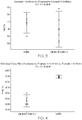
- FIGS. 3-4 graphically compare an integral balloon shaft 22 with a 6 x 40 mm balloon 24 (Example 1), to a commercially available 2 layer balloon tacked or bonded onto a shaft (Comparative Example A).
- the burst pressures of the integral balloon 24 are comparable to the burst pressures of the tacked balloon of Comparative Example A; and the double wall thicknesses of the integral balloon 24 is slightly greater than the double wall thickness of the tacked balloon of Comparative Example A.
- the integral balloon shaft 22 forms a part of a balloon catheter 20 that can be employed in any of a variety of medical procedures including, but not limited to angioplasty (PTCA) procedures; for delivery medical devices such as stents or valves; genitourinary procedures; biliary procedures; neurological procedures; peripheral vascular procedures; renal procedures; etc.
- PTCA angioplasty
- the balloon catheter 20 is particularly useful for procedures that require high pressure to treat, such as a blockage of a major artery, at an AV Fistula vein or graft where resistant lesions occur as a result of hemodialysis, or where heavy calcification and arterial elasticity present extreme challenges to clinicians.
- the balloon catheter 20 includes an inner shaft 26 positioned inside the balloon shaft 22 (e.g. FIG. 2 ).
- the inner shaft 26 has a length greater than the length of the balloon shaft 22, and an outer diameter less than the inner diameter of the balloon shaft 22.
- the inner shaft 26 is tubular and defines a guidewire lumen for passage of a guidewire 32 therethrough (e.g. FIGS. 1-2 ).
- the inner shaft 26 comprises a polymer.
- the inner shaft can have a single polymeric layer or a plurality of polymeric layers. Any suitable polymer can be used for the inner shaft 26. Examples of suitable polymers for the inner shaft include, but are not limited to: high density polypropylene (e.g. Marlex®); poly(ether-block-amides) (e.g. Pebax®); polyamides (e.g. Grilamid®); and combinations thereof. Further, the inner shaft can have a reinforcement layer, as is known in the art.
- a distal end region of the inner shaft 26 and a distal end region of the balloon shaft 22 can be secured to one another to form a distal tip 28 of the balloon catheter 20 (e.g. FIG. 2 ). Any suitable means can be used to secure the shafts 22, 26 to one another.
- the distal tip can be a tapered bumper tip.
- the guidewire lumen extends through the distal tip (e.g. FIGS. 1-2 ).
- the distal tip 28 has a length of about 4 mm to about 5 mm.
- the distal end of the balloon 24 is proximal to the distal end of the balloon shaft 22, and is proximal to the distal end of the balloon catheter 20.
- a balloon catheter 20 as described herein includes a manifold/handle 30 (herein after manifold) at the proximal end (e.g. FIG. 1 ).
- the manifold is secured to both the balloon shaft 22 and the inner shaft 26.
- the manifold 30 has a plurality of outlets 31.
- the manifold has two outlets with one outlet in communication with the inflation lumen of the balloon shaft 22, and another outlet in communication with the guidewire lumen of the inner shaft 26.
- the balloon catheter 20 has three components: the balloon shaft 22 with integral balloon 24; an inner shaft 26; and a manifold 30.
- the balloon catheter 20 may include one or more areas, bands, coatings, members, etc. that is (are) detectable by imaging modalities such as X-Ray, MRI, ultrasound, etc. In some embodiments at least a portion of the balloon catheter 20 is at least partially radiopaque.
- the balloon catheter 20 is configured to include one or more mechanisms for the delivery of a therapeutic agent.
- the agent will be in the form of a coating or other layer (or layers) of material placed on a surface of the balloon catheter 20.
- the surface with a coating or layer can be the outer surface, the inner surface, or both the inner and outer surfaces.
- the balloon 24 has a coating of therapeutic agent.
- a therapeutic agent may be a drug or other pharmaceutical product such as non-genetic agents, genetic agents, cellular material, etc.
- suitable non-genetic therapeutic agents include but are not limited to: anti-thrombogenic agents such as heparin, heparin derivatives, vascular cell growth promoters, growth factor inhibitors, Paclitaxel, etc.
- an agent includes a genetic therapeutic agent, such a genetic agent may include but is not limited to: DNA, RNA and their respective derivatives and/or components; hedgehog proteins, etc.
- the cellular material may include but is not limited to: cells of human origin and/or non-human origin as well as their respective components and/or derivatives thereof.
- the polymer agent may be a polystyrene-polyisobutylene-polystyrene triblock copolymer (SIBS), polyethylene oxide, silicone rubber and/or any other suitable substrate.
- SIBS polystyrene-polyisobutylene-polystyrene triblock copolymer
- a balloon shaft 22 with an integral balloon 24 is formed from an extruded tube.
- the extruded tube is formed into a stretched extruded tube before a section of the extruded tube is formed into a balloon 24.
- the extruded tube can be placed into a stretching machine with two clamps, for example, one movable clamp and one stationary clamp.
- the movable clamp is attached to the distal end region of the extruded tube and the stationary clamp is attached to the proximal end region of the extruded tube.
- a gas pressure source is in communication with the lumen of the extruded tube.
- the stationary clamp may have rubber pads which fix the extruded tube in position, but allows gas flow to pressurize the extruded tube.
- the extruded tube is subjected to a multistage stretching process having three stretching steps or stages.
- first stretching step a selected portion of the distal end region of the extruded tube is stretched at a first pressure and a first temperature, where the first pressure is equal to ambient pressure.
- second stretching step the extruded tube is stretched at a second pressure and the first temperature until the extruded tube is stretched to 25 to 75%, preferably, 35-65%, more preferably 45-55%, and most preferably 50% the desired final length, where the second pressure is greater than the first pressure.
- the extruded tube is stretched at a third pressure and the first temperature until the extruded tube is stretched to the final stretched length, where the third temperature is less than the second pressure and greater than the first pressure.
- the first stretching step typically reduces the dimensions of the distal end region of the extruded tube, and the third stretching step advantageously optimizes the material modulus, the inner diameter, and the outer diameter of the stretched extruded tube.
- the stretched extruded tube is quenched at a second temperature less than ambient temperature, and the pressure is reduced from the third pressure. Then a portion of the stretched extruded tube is placed into a balloon mold for formation of the integral balloon 24.
- the balloon mold may have three sections, a distal end section, a body section, and a proximal end section. While in the mold, the stretched tube is pressurized to a fourth pressure at an elevated third temperature to form the balloon 24, where the third temperature is greater than the first temperature; the balloon 24 is heat set at a fourth temperature greater than the third temperature; and then quenched at a reduced fourth temperature for removal of the balloon shaft 22 with an integral balloon 24 from the mold, where the fourth temperature is less than ambient temperature.
- This manufacturing method is a simplified manufacturing process that achieves the same superior balloon properties as commercially available balloons. This method is described in greater detail with reference to Examples A-E.
- the extruded tube is placed into the two clamps of the stretching machine. An initial distance of 516 mm separates the two clamps.
- a distal region of the extruded tube next to the movable clamp is contact heated to a first temperature, and the extruded tube is stretched to form a distal neck with transition.
- the first temperature is 80° C; the first pressure is ambient pressure; and the distal region is approximately 127 mm (5 inches).
- the extruded tube is stretched to a distance of about 716 mm in an 80° C hot bath, at a velocity of 50 mm/sec, and an inflation pressure of 280 psi (1.930532x10 6 Pa).
- the third stretching step begins.
- the pressure is reduced to 180 psi (1.241056x10 6 Pa) and the extruded tube is stretched to a final length.
- the stretched extruded tube is quenched in a 11° C bath, the pressure is reduced from 180 psi (1.241056x10 6 Pa), and the stretched extruded tube is released from the two clamps that are separated at least by 990 mm.
- the extruded tube is placed into the two clamps of the stretching machine.
- An initial distance of about 366 mm separates the two clamps.
- a distal region of the extruded tube next to the movable clamp is contact heated to a first temperature, and the extruded tube is stretched to form a distal neck with transition.
- the distal region has a length of about 25 mm; the first temperature is 80° C; the pressure is ambient pressure; and the extruded tube is stretched a distance of about 416 mm.
- the extruded tube is stretched in an 80° C hot bath at a velocity of 50 mm/sec to a distance of about 716 mm at an inflation pressure of 357 psi (2.461428x10 6 Pa).
- the third stretching step begins.
- the pressure is reduced to 290 psi (1.9994796x10 6 Pa) and stretched to about 990 mm.
- the stretched extruded tube is quenched in a 11° C bath, the pressure is reduced from 290 psi (1.9994796x10 6 Pa), and the stretched extruded tube released from the two clamps that separated at least by 990 mm.
- the extruded tube is placed into the two clamps of the stretching machine.
- An initial distance of about 336 mm separates the two clamps.
- a distal region of the extruded tube next to the movable clamp is contact heated to a first temperature, and the extruded tube is stretched to form a distal neck with transition.
- the distal region has a length of about 25 mm; the first temperature is 80° C; the pressure is ambient pressure; and the extruded tube is stretched a distance of about 386 mm.
- the extruded tube is stretched in an 80° C hot bath at a velocity of 50 mm/sec to a distance of about 716 mm at an inflation pressure of 275 psi (1.896058x10 6 Pa).
- the third stretching step begins.
- the pressure is reduced to 190 psi (1.310039x10 6 Pa), and the extruded tube is stretched to about 990 mm.
- the stretched tube is quenched in an 11° C bath, the pressure is reduced from 190 psi (1.310039x10 6 Pa), and the stretched tube released from the two clamps that are separated by 990 mm.
- a balloon mold with a 50.8 mm (2 inches) distal end section, a 40 mm body section, and a 101.6 mm (4 inches) proximal end section is used to form a 40 mm balloon.
- the transition between the smaller outer diameter distal end region and larger outer diameter proximal end region of the stretched tube is placed in the proximal mold section.
- the stretched tube and mold are placed into a mold holder and then onto the molding machine arm.
- the stretched tube is pressurized at a fourth pressure and placed in bath at a third temperature until the balloon is formed.
- the fourth pressure may be less than or greater than the third pressure.
- the mold is transferred to a heat set station set at a fourth temperature for 60-90 seconds.
- the fourth temperature is greater than the first temperature.
- the mold is transferred to a quench bath at a fifth temperature to cool the shaft and mold to allow for removal of the balloon shaft 22 with the integral balloon 24 from the mold.
- a quench bath at a fifth temperature to cool the shaft and mold to allow for removal of the balloon shaft 22 with the integral balloon 24 from the mold.
- the fifth temperature less than the first temperature
- the stretched tube in the balloon mold is pressurized with nitrogen gas at 500 psi (3.4473786x10 6 Pa) and placed in a 95° C bath until the balloon is formed.
- the mold is transferred to a heat set station set for 125° C for one (1) minute before the mold is transferred to a 10° C quench bath to cool the shaft and mold to allow for removal of the balloon shaft 22 with the integral balloon 24 from the mold.
- the stretched tube in the balloon mold is pressurized with nitrogen gas at 265 psi (1.827111x10 6 Pa) and placed in a 95° C bath until the balloon is formed.
- the mold is transferred to a heat set station set for 125° C for one (1) minute before the mold is transferred to a 10° C quench bath to cool the shaft and mold to allow for removal of the balloon shaft 22 with the integral balloon 24 from the mold.
- the stretched tube in the balloon mold is pressurized with nitrogen gas at 300 psi (2.068427x10 6 Pa) and placed in a 95° C bath until the balloon is formed.
- the mold is transferred to a heat set station set for 125° C for one (1) minute before the mold is transferred to a 10° C quench bath to cool the shaft and mold to allow for removal of the balloon shaft 22 with the integral balloon 24 from the mold.
- a balloon shaft 22 with integral balloon 24 can form a part of a balloon catheter 20.
- a method of forming a balloon catheter 20 includes: inserting a polymeric tube into the lumen of a shaft 22 with the integral balloon 24, where the shaft 22 is considered to be an outer shaft and the polymeric tube is considered to be an inner shaft 26; securing the outer shaft 22 and inner shaft 26 to one another to form a shaft assembly; and attaching a manifold 30 to a proximal end of the shaft assembly to form the balloon catheter 20.
- any suitable means can be used to secure the outer shaft 22 and inner shaft 26.
- a hot jaw, a laser bonder, a means of fusion, or a means of adhesion can be used to fuse the outer shaft 22 and inner shaft 26.
- securing the outer shaft 22 and inner shaft 26 to one another forms a distal tip 28, such as a tapered bumper tip.
- about 4-5 mm of the outer shaft 22 distal to the balloon 24 is fused to the inner shaft 26.
- any suitable means can be used to attach the manifold 30 to the shaft assembly.
- a UV cure adhesive for example, a two part epoxy; a high strength adhesive; or any other means of adhesion can be used to attach the manifold.
- a "high strength adhesive” is an adhesive capable of withstanding internal pressure of 500 psi (3.447379x10 6 Pa) and higher.
Landscapes
- Health & Medical Sciences (AREA)
- Life Sciences & Earth Sciences (AREA)
- Heart & Thoracic Surgery (AREA)
- Engineering & Computer Science (AREA)
- Hematology (AREA)
- Anesthesiology (AREA)
- Biomedical Technology (AREA)
- Pulmonology (AREA)
- Biophysics (AREA)
- Animal Behavior & Ethology (AREA)
- General Health & Medical Sciences (AREA)
- Public Health (AREA)
- Veterinary Medicine (AREA)
- Child & Adolescent Psychology (AREA)
- Manufacturing & Machinery (AREA)
- Materials For Medical Uses (AREA)
- Media Introduction/Drainage Providing Device (AREA)
Claims (14)
- Procédé de formation d'une tige multicouche (22), comprenant :une première étape d'étirage dans laquelle une partie d'une région d'extrémité distale d'un tube polymère multicouche est étirée sous une première pression et à une première température, et la première pression est égale à la pression ambiante ;une deuxième étape d'étirage dans laquelle le tube polymère multicouche est étiré sous une deuxième pression et à la première température jusqu'à ce que le tube extrudé soit étiré à 25 à 75 %, de préférence à 35 à 65 %, mieux encore à 45 à 55 %, et tout spécialement à 50 % de la longueur finale souhaitée, et la deuxième pression est supérieure à la première pression ;une troisième étape d'étirage dans laquelle le tube polymère multicouche est étiré sous une troisième pression et à la première température pour former un tube polymère multicouche étiré ayant la longueur étirée finale, et la troisième pression est inférieure à la deuxième pression et supérieure à la première pression ; etune étape de formation de ballonnet dans laquelle une section du tube polymère multicouche étiré est mis sous la forme d'un ballonnet monobloc (24),dans lequel la longueur de tige totale de la tige multicouche (22) avec le ballonnet monobloc (24) est d'au moins 70 cm.
- Procédé selon la revendication 1, dans lequel la formation du ballonnet monobloc (24) comprend :le placement de la section du tube polymère multicouche étiré dans un moule de ballonnet ;la pressurisation du tube polymère multicouche étiré sous une quatrième pression à une deuxième température pour mettre la section sous la forme du ballonnet monobloc (24), dans laquelle la quatrième pression est différente des première, deuxième et troisième pressions, et la deuxième température est supérieure à la première température ; etla stabilisation à la chaleur du ballonnet monobloc (24) à une troisième température supérieure à la deuxième température.
- Procédé selon l'une quelconque des revendications 1 et 2, comprenant en outre une première étape de trempe après la troisième étape d'étirage, dans lequel, durant la première étape de trempe, la température est réduite à une quatrième température inférieure à la première température et la pression est réduite par rapport à la troisième pression.
- Procédé selon la revendication 3, lequel procédé comprend en outre une deuxième étape de trempe après l'étape de stabilisation à la chaleur, dans lequel, durant la deuxième étape de trempe, la température est réduite à une cinquième température inférieure à la première température ;
dans lequel en outre le ballonnet monobloc (24) est retiré du moule après la deuxième étape de trempe. - Procédé selon l'une quelconque des revendications 1 à 4, dans lequel le tube polymère multicouche est formé par coextrusion.
- Procédé selon la revendication 1, dans lequel le ballonnet monobloc (24) a une résistance à l'éclatement d'au moins 30 000 psi (3,068427 x 10⁸ Pa).
- Procédé selon l'une quelconque des revendications 1 et 6, dans lequel le ballonnet monobloc (24) a une distension par atmosphère entre 60,7950∗104 et 1,419∗106 N/m2 (entre 6 et 14 atmosphères) qui n'est pas supérieure à 0,9 %.
- Procédé selon l'une quelconque des revendications 1, 6 et 7, dans lequel le ballonnet monobloc (24) a une épaisseur de double paroi de 0,0254 mm à 0,127 mm.
- Procédé selon l'une quelconque des revendications 1 et 6 à 8, dans lequel le ballonnet monobloc (24) a un diamètre extérieur de ballonnet de 1,5 mm à 28 mm.
- Procédé selon l'une quelconque des revendications 1 et 6 à 9, dans lequel la tige (22) a un diamètre extérieur de tige qui est de 15 à 55 % du diamètre extérieur de ballonnet.
- Procédé selon l'une quelconque des revendications 1 et 6 à 10, dans lequel la tige (22) a un diamètre intérieur d'arbre qui est de 11 à 50 % du diamètre extérieur de ballonnet.
- Procédé selon l'une quelconque des revendications 1 et 6 à 11, dans lequel la tige (22) a une couche extérieure formée de nylon et une couche intérieure formée de poly(éther-bloc-amide).
- Procédé selon l'une quelconque des revendications 1 et 6 à 12, dans lequel la tige (22) a une couche intérieure formée de poly(éther-bloc-amide), une couche centrale formée de nylon, et une couche extérieure formée de poly(éther-bloc-amide).
- Procédé selon l'une quelconque des revendications 12 et 13, dans lequel le nylon est choisi dans le groupe constitué par le nylon 12 ; le nylon 6 ; le nylon 6/10 ; le nylon 6/12 ; le nylon 11 ; et les nylons aromatiques ; et le poly(éther-bloc-amide) a une dureté Shore D de 60 à 74 D.
Applications Claiming Priority (2)
| Application Number | Priority Date | Filing Date | Title |
|---|---|---|---|
| US201461994437P | 2014-05-16 | 2014-05-16 | |
| PCT/US2015/029041 WO2015175252A1 (fr) | 2014-05-16 | 2015-05-04 | Cathéter à ballonnet multicouche à faible coût à haute pression |
Publications (2)
| Publication Number | Publication Date |
|---|---|
| EP3142738A1 EP3142738A1 (fr) | 2017-03-22 |
| EP3142738B1 true EP3142738B1 (fr) | 2020-11-04 |
Family
ID=53177901
Family Applications (1)
| Application Number | Title | Priority Date | Filing Date |
|---|---|---|---|
| EP15722638.2A Active EP3142738B1 (fr) | 2014-05-16 | 2015-05-04 | Cathéter à ballonnet multicouche à faible coût à haute pression |
Country Status (4)
| Country | Link |
|---|---|
| US (1) | US20150328441A1 (fr) |
| EP (1) | EP3142738B1 (fr) |
| CN (1) | CN106659872B (fr) |
| WO (1) | WO2015175252A1 (fr) |
Families Citing this family (4)
| Publication number | Priority date | Publication date | Assignee | Title |
|---|---|---|---|---|
| JP6668131B2 (ja) | 2016-03-23 | 2020-03-18 | テルモ株式会社 | バルーンカテーテルおよびその製造方法並びに処置方法 |
| WO2017164278A1 (fr) | 2016-03-23 | 2017-09-28 | テルモ株式会社 | Cathéter à ballonnet, procédé de fabrication associé, et procédé de traitement |
| JP2017169738A (ja) | 2016-03-23 | 2017-09-28 | テルモ株式会社 | バルーンカテーテルおよびその製造方法並びに処置方法 |
| CN111420249A (zh) * | 2020-04-28 | 2020-07-17 | 鼎科医疗技术(苏州)有限公司 | 一种耐折性血管扩张球囊导管 |
Family Cites Families (10)
| Publication number | Priority date | Publication date | Assignee | Title |
|---|---|---|---|---|
| US6124007A (en) * | 1996-03-06 | 2000-09-26 | Scimed Life Systems Inc | Laminate catheter balloons with additive burst strength and methods for preparation of same |
| DE69727234T2 (de) * | 1996-07-23 | 2004-11-11 | Scimed Life Systems, Inc., Maple Grove | Verfahren zur herstellung von hochfesten dilatationsballons mit hoher compliance zur behandlung gastrointestinaler schädigungen |
| US6287506B1 (en) * | 1998-07-09 | 2001-09-11 | Schneider (Usa) Inc. | Method for reducing dilation balloon cone stiffness |
| US6695809B1 (en) * | 1999-09-13 | 2004-02-24 | Advanced Cardiovascular Systems, Inc. | Catheter balloon with a discontinuous elastomeric outer layer |
| US6977103B2 (en) * | 1999-10-25 | 2005-12-20 | Boston Scientific Scimed, Inc. | Dimensionally stable balloons |
| US20090198266A1 (en) * | 2008-02-01 | 2009-08-06 | Jbm Medical Llc | Devices and methods for abdominal surgery |
| US20100042199A1 (en) * | 2008-08-18 | 2010-02-18 | Burton David G | Dilation balloon catheter and methods of use thereof |
| US8052638B2 (en) * | 2008-11-26 | 2011-11-08 | Abbott Cardiovascular Systems, Inc. | Robust multi-layer balloon |
| US20150290434A1 (en) * | 2012-11-19 | 2015-10-15 | Abbott Cardiovascular System Inc. | Multilayer balloon for a catheter |
| CN103055411B (zh) * | 2013-01-25 | 2014-03-12 | 业聚医疗器械(深圳)有限公司 | 球囊导管及其制作方法 |
-
2015
- 2015-05-04 EP EP15722638.2A patent/EP3142738B1/fr active Active
- 2015-05-04 CN CN201580038909.9A patent/CN106659872B/zh active Active
- 2015-05-04 US US14/703,325 patent/US20150328441A1/en not_active Abandoned
- 2015-05-04 WO PCT/US2015/029041 patent/WO2015175252A1/fr not_active Ceased
Non-Patent Citations (1)
| Title |
|---|
| None * |
Also Published As
| Publication number | Publication date |
|---|---|
| CN106659872B (zh) | 2020-10-02 |
| EP3142738A1 (fr) | 2017-03-22 |
| WO2015175252A1 (fr) | 2015-11-19 |
| US20150328441A1 (en) | 2015-11-19 |
| CN106659872A (zh) | 2017-05-10 |
Similar Documents
| Publication | Publication Date | Title |
|---|---|---|
| US7226472B2 (en) | Catheter balloon with advantageous cone design | |
| EP2437840B1 (fr) | Tube de cathéter robuste | |
| US9821147B2 (en) | Multilayer balloon for a catheter | |
| EP2334347B1 (fr) | Ballonnet medical multicouche | |
| US9539368B2 (en) | Robust catheter tubing | |
| US6695809B1 (en) | Catheter balloon with a discontinuous elastomeric outer layer | |
| US6841029B2 (en) | Surface modification of expanded ultra high molecular weight polyethylene (eUHMWPE) for improved bondability | |
| AU2017295675B2 (en) | High-pressure dilation catheter balloon | |
| US8070719B2 (en) | Low compliant catheter tubing | |
| EP2919847B1 (fr) | Ballonnet multicouche pour un cathéter | |
| JPH10234845A (ja) | 共に押し出されたバルーンおよびその製造方法 | |
| US20150105815A1 (en) | High pressure tear resistant balloon | |
| US20090254113A1 (en) | Dilatation balloon with ridges and methods | |
| WO2008023696A1 (fr) | cathéter à ballonnet | |
| US20150290434A1 (en) | Multilayer balloon for a catheter | |
| US6939321B2 (en) | Catheter balloon having improved balloon bonding | |
| US20150328441A1 (en) | High Pressure Low Cost Multilayer Balloon Catheter | |
| US20040122464A1 (en) | Balloon catheter having a microporous distal tip | |
| JP5026278B2 (ja) | 医療用複合バルーン | |
| JP4402218B2 (ja) | バルーンカテーテル |
Legal Events
| Date | Code | Title | Description |
|---|---|---|---|
| STAA | Information on the status of an ep patent application or granted ep patent |
Free format text: STATUS: THE INTERNATIONAL PUBLICATION HAS BEEN MADE |
|
| PUAI | Public reference made under article 153(3) epc to a published international application that has entered the european phase |
Free format text: ORIGINAL CODE: 0009012 |
|
| STAA | Information on the status of an ep patent application or granted ep patent |
Free format text: STATUS: REQUEST FOR EXAMINATION WAS MADE |
|
| 17P | Request for examination filed |
Effective date: 20161216 |
|
| AK | Designated contracting states |
Kind code of ref document: A1 Designated state(s): AL AT BE BG CH CY CZ DE DK EE ES FI FR GB GR HR HU IE IS IT LI LT LU LV MC MK MT NL NO PL PT RO RS SE SI SK SM TR |
|
| AX | Request for extension of the european patent |
Extension state: BA ME |
|
| DAV | Request for validation of the european patent (deleted) | ||
| DAX | Request for extension of the european patent (deleted) | ||
| REG | Reference to a national code |
Ref country code: DE Ref legal event code: R079 Ref document number: 602015061468 Country of ref document: DE Free format text: PREVIOUS MAIN CLASS: A61M0025100000 Ipc: B29C0057000000 |
|
| RIC1 | Information provided on ipc code assigned before grant |
Ipc: B29C 57/00 20060101AFI20190902BHEP Ipc: B29C 55/22 20060101ALI20190902BHEP Ipc: A61M 25/00 20060101ALI20190902BHEP Ipc: A61M 25/10 20130101ALI20190902BHEP Ipc: B29L 31/00 20060101ALI20190902BHEP |
|
| GRAP | Despatch of communication of intention to grant a patent |
Free format text: ORIGINAL CODE: EPIDOSNIGR1 |
|
| STAA | Information on the status of an ep patent application or granted ep patent |
Free format text: STATUS: GRANT OF PATENT IS INTENDED |
|
| INTG | Intention to grant announced |
Effective date: 20200107 |
|
| GRAJ | Information related to disapproval of communication of intention to grant by the applicant or resumption of examination proceedings by the epo deleted |
Free format text: ORIGINAL CODE: EPIDOSDIGR1 |
|
| STAA | Information on the status of an ep patent application or granted ep patent |
Free format text: STATUS: REQUEST FOR EXAMINATION WAS MADE |
|
| GRAP | Despatch of communication of intention to grant a patent |
Free format text: ORIGINAL CODE: EPIDOSNIGR1 |
|
| INTC | Intention to grant announced (deleted) | ||
| STAA | Information on the status of an ep patent application or granted ep patent |
Free format text: STATUS: GRANT OF PATENT IS INTENDED |
|
| INTG | Intention to grant announced |
Effective date: 20200618 |
|
| GRAS | Grant fee paid |
Free format text: ORIGINAL CODE: EPIDOSNIGR3 |
|
| GRAA | (expected) grant |
Free format text: ORIGINAL CODE: 0009210 |
|
| STAA | Information on the status of an ep patent application or granted ep patent |
Free format text: STATUS: THE PATENT HAS BEEN GRANTED |
|
| AK | Designated contracting states |
Kind code of ref document: B1 Designated state(s): AL AT BE BG CH CY CZ DE DK EE ES FI FR GB GR HR HU IE IS IT LI LT LU LV MC MK MT NL NO PL PT RO RS SE SI SK SM TR |
|
| REG | Reference to a national code |
Ref country code: GB Ref legal event code: FG4D |
|
| REG | Reference to a national code |
Ref country code: CH Ref legal event code: EP |
|
| REG | Reference to a national code |
Ref country code: AT Ref legal event code: REF Ref document number: 1330248 Country of ref document: AT Kind code of ref document: T Effective date: 20201115 |
|
| REG | Reference to a national code |
Ref country code: DE Ref legal event code: R096 Ref document number: 602015061468 Country of ref document: DE |
|
| REG | Reference to a national code |
Ref country code: IE Ref legal event code: FG4D |
|
| REG | Reference to a national code |
Ref country code: NL Ref legal event code: FP |
|
| REG | Reference to a national code |
Ref country code: AT Ref legal event code: MK05 Ref document number: 1330248 Country of ref document: AT Kind code of ref document: T Effective date: 20201104 |
|
| PG25 | Lapsed in a contracting state [announced via postgrant information from national office to epo] |
Ref country code: FI Free format text: LAPSE BECAUSE OF FAILURE TO SUBMIT A TRANSLATION OF THE DESCRIPTION OR TO PAY THE FEE WITHIN THE PRESCRIBED TIME-LIMIT Effective date: 20201104 Ref country code: RS Free format text: LAPSE BECAUSE OF FAILURE TO SUBMIT A TRANSLATION OF THE DESCRIPTION OR TO PAY THE FEE WITHIN THE PRESCRIBED TIME-LIMIT Effective date: 20201104 Ref country code: PT Free format text: LAPSE BECAUSE OF FAILURE TO SUBMIT A TRANSLATION OF THE DESCRIPTION OR TO PAY THE FEE WITHIN THE PRESCRIBED TIME-LIMIT Effective date: 20210304 Ref country code: NO Free format text: LAPSE BECAUSE OF FAILURE TO SUBMIT A TRANSLATION OF THE DESCRIPTION OR TO PAY THE FEE WITHIN THE PRESCRIBED TIME-LIMIT Effective date: 20210204 Ref country code: GR Free format text: LAPSE BECAUSE OF FAILURE TO SUBMIT A TRANSLATION OF THE DESCRIPTION OR TO PAY THE FEE WITHIN THE PRESCRIBED TIME-LIMIT Effective date: 20210205 |
|
| PG25 | Lapsed in a contracting state [announced via postgrant information from national office to epo] |
Ref country code: LV Free format text: LAPSE BECAUSE OF FAILURE TO SUBMIT A TRANSLATION OF THE DESCRIPTION OR TO PAY THE FEE WITHIN THE PRESCRIBED TIME-LIMIT Effective date: 20201104 Ref country code: PL Free format text: LAPSE BECAUSE OF FAILURE TO SUBMIT A TRANSLATION OF THE DESCRIPTION OR TO PAY THE FEE WITHIN THE PRESCRIBED TIME-LIMIT Effective date: 20201104 Ref country code: SE Free format text: LAPSE BECAUSE OF FAILURE TO SUBMIT A TRANSLATION OF THE DESCRIPTION OR TO PAY THE FEE WITHIN THE PRESCRIBED TIME-LIMIT Effective date: 20201104 Ref country code: IS Free format text: LAPSE BECAUSE OF FAILURE TO SUBMIT A TRANSLATION OF THE DESCRIPTION OR TO PAY THE FEE WITHIN THE PRESCRIBED TIME-LIMIT Effective date: 20210304 Ref country code: BG Free format text: LAPSE BECAUSE OF FAILURE TO SUBMIT A TRANSLATION OF THE DESCRIPTION OR TO PAY THE FEE WITHIN THE PRESCRIBED TIME-LIMIT Effective date: 20210204 Ref country code: ES Free format text: LAPSE BECAUSE OF FAILURE TO SUBMIT A TRANSLATION OF THE DESCRIPTION OR TO PAY THE FEE WITHIN THE PRESCRIBED TIME-LIMIT Effective date: 20201104 Ref country code: AT Free format text: LAPSE BECAUSE OF FAILURE TO SUBMIT A TRANSLATION OF THE DESCRIPTION OR TO PAY THE FEE WITHIN THE PRESCRIBED TIME-LIMIT Effective date: 20201104 |
|
| REG | Reference to a national code |
Ref country code: LT Ref legal event code: MG9D |
|
| PG25 | Lapsed in a contracting state [announced via postgrant information from national office to epo] |
Ref country code: HR Free format text: LAPSE BECAUSE OF FAILURE TO SUBMIT A TRANSLATION OF THE DESCRIPTION OR TO PAY THE FEE WITHIN THE PRESCRIBED TIME-LIMIT Effective date: 20201104 |
|
| PG25 | Lapsed in a contracting state [announced via postgrant information from national office to epo] |
Ref country code: SM Free format text: LAPSE BECAUSE OF FAILURE TO SUBMIT A TRANSLATION OF THE DESCRIPTION OR TO PAY THE FEE WITHIN THE PRESCRIBED TIME-LIMIT Effective date: 20201104 Ref country code: CZ Free format text: LAPSE BECAUSE OF FAILURE TO SUBMIT A TRANSLATION OF THE DESCRIPTION OR TO PAY THE FEE WITHIN THE PRESCRIBED TIME-LIMIT Effective date: 20201104 Ref country code: EE Free format text: LAPSE BECAUSE OF FAILURE TO SUBMIT A TRANSLATION OF THE DESCRIPTION OR TO PAY THE FEE WITHIN THE PRESCRIBED TIME-LIMIT Effective date: 20201104 Ref country code: LT Free format text: LAPSE BECAUSE OF FAILURE TO SUBMIT A TRANSLATION OF THE DESCRIPTION OR TO PAY THE FEE WITHIN THE PRESCRIBED TIME-LIMIT Effective date: 20201104 Ref country code: RO Free format text: LAPSE BECAUSE OF FAILURE TO SUBMIT A TRANSLATION OF THE DESCRIPTION OR TO PAY THE FEE WITHIN THE PRESCRIBED TIME-LIMIT Effective date: 20201104 Ref country code: SK Free format text: LAPSE BECAUSE OF FAILURE TO SUBMIT A TRANSLATION OF THE DESCRIPTION OR TO PAY THE FEE WITHIN THE PRESCRIBED TIME-LIMIT Effective date: 20201104 |
|
| REG | Reference to a national code |
Ref country code: DE Ref legal event code: R097 Ref document number: 602015061468 Country of ref document: DE |
|
| PG25 | Lapsed in a contracting state [announced via postgrant information from national office to epo] |
Ref country code: DK Free format text: LAPSE BECAUSE OF FAILURE TO SUBMIT A TRANSLATION OF THE DESCRIPTION OR TO PAY THE FEE WITHIN THE PRESCRIBED TIME-LIMIT Effective date: 20201104 |
|
| PLBE | No opposition filed within time limit |
Free format text: ORIGINAL CODE: 0009261 |
|
| STAA | Information on the status of an ep patent application or granted ep patent |
Free format text: STATUS: NO OPPOSITION FILED WITHIN TIME LIMIT |
|
| 26N | No opposition filed |
Effective date: 20210805 |
|
| PG25 | Lapsed in a contracting state [announced via postgrant information from national office to epo] |
Ref country code: IT Free format text: LAPSE BECAUSE OF FAILURE TO SUBMIT A TRANSLATION OF THE DESCRIPTION OR TO PAY THE FEE WITHIN THE PRESCRIBED TIME-LIMIT Effective date: 20201104 Ref country code: AL Free format text: LAPSE BECAUSE OF FAILURE TO SUBMIT A TRANSLATION OF THE DESCRIPTION OR TO PAY THE FEE WITHIN THE PRESCRIBED TIME-LIMIT Effective date: 20201104 |
|
| PG25 | Lapsed in a contracting state [announced via postgrant information from national office to epo] |
Ref country code: SI Free format text: LAPSE BECAUSE OF FAILURE TO SUBMIT A TRANSLATION OF THE DESCRIPTION OR TO PAY THE FEE WITHIN THE PRESCRIBED TIME-LIMIT Effective date: 20201104 |
|
| REG | Reference to a national code |
Ref country code: CH Ref legal event code: PL |
|
| GBPC | Gb: european patent ceased through non-payment of renewal fee |
Effective date: 20210504 |
|
| PG25 | Lapsed in a contracting state [announced via postgrant information from national office to epo] |
Ref country code: CH Free format text: LAPSE BECAUSE OF NON-PAYMENT OF DUE FEES Effective date: 20210531 Ref country code: LU Free format text: LAPSE BECAUSE OF NON-PAYMENT OF DUE FEES Effective date: 20210504 Ref country code: MC Free format text: LAPSE BECAUSE OF FAILURE TO SUBMIT A TRANSLATION OF THE DESCRIPTION OR TO PAY THE FEE WITHIN THE PRESCRIBED TIME-LIMIT Effective date: 20201104 Ref country code: LI Free format text: LAPSE BECAUSE OF NON-PAYMENT OF DUE FEES Effective date: 20210531 |
|
| REG | Reference to a national code |
Ref country code: BE Ref legal event code: MM Effective date: 20210531 |
|
| PG25 | Lapsed in a contracting state [announced via postgrant information from national office to epo] |
Ref country code: GB Free format text: LAPSE BECAUSE OF NON-PAYMENT OF DUE FEES Effective date: 20210504 |
|
| PG25 | Lapsed in a contracting state [announced via postgrant information from national office to epo] |
Ref country code: IS Free format text: LAPSE BECAUSE OF FAILURE TO SUBMIT A TRANSLATION OF THE DESCRIPTION OR TO PAY THE FEE WITHIN THE PRESCRIBED TIME-LIMIT Effective date: 20210304 Ref country code: FR Free format text: LAPSE BECAUSE OF NON-PAYMENT OF DUE FEES Effective date: 20210531 |
|
| PG25 | Lapsed in a contracting state [announced via postgrant information from national office to epo] |
Ref country code: BE Free format text: LAPSE BECAUSE OF NON-PAYMENT OF DUE FEES Effective date: 20210531 |
|
| PG25 | Lapsed in a contracting state [announced via postgrant information from national office to epo] |
Ref country code: HU Free format text: LAPSE BECAUSE OF FAILURE TO SUBMIT A TRANSLATION OF THE DESCRIPTION OR TO PAY THE FEE WITHIN THE PRESCRIBED TIME-LIMIT; INVALID AB INITIO Effective date: 20150504 |
|
| PG25 | Lapsed in a contracting state [announced via postgrant information from national office to epo] |
Ref country code: CY Free format text: LAPSE BECAUSE OF FAILURE TO SUBMIT A TRANSLATION OF THE DESCRIPTION OR TO PAY THE FEE WITHIN THE PRESCRIBED TIME-LIMIT Effective date: 20201104 |
|
| PG25 | Lapsed in a contracting state [announced via postgrant information from national office to epo] |
Ref country code: MK Free format text: LAPSE BECAUSE OF FAILURE TO SUBMIT A TRANSLATION OF THE DESCRIPTION OR TO PAY THE FEE WITHIN THE PRESCRIBED TIME-LIMIT Effective date: 20201104 |
|
| PG25 | Lapsed in a contracting state [announced via postgrant information from national office to epo] |
Ref country code: MT Free format text: LAPSE BECAUSE OF FAILURE TO SUBMIT A TRANSLATION OF THE DESCRIPTION OR TO PAY THE FEE WITHIN THE PRESCRIBED TIME-LIMIT Effective date: 20201104 |
|
| PG25 | Lapsed in a contracting state [announced via postgrant information from national office to epo] |
Ref country code: TR Free format text: LAPSE BECAUSE OF FAILURE TO SUBMIT A TRANSLATION OF THE DESCRIPTION OR TO PAY THE FEE WITHIN THE PRESCRIBED TIME-LIMIT Effective date: 20201104 |
|
| PGFP | Annual fee paid to national office [announced via postgrant information from national office to epo] |
Ref country code: NL Payment date: 20260421 Year of fee payment: 12 |
|
| PGFP | Annual fee paid to national office [announced via postgrant information from national office to epo] |
Ref country code: DE Payment date: 20260421 Year of fee payment: 12 |
|
| PGFP | Annual fee paid to national office [announced via postgrant information from national office to epo] |
Ref country code: IE Payment date: 20260422 Year of fee payment: 12 |