EP3142820B1 - Ensemble gabarit et procédé - Google Patents
Ensemble gabarit et procédé Download PDFInfo
- Publication number
- EP3142820B1 EP3142820B1 EP15728579.2A EP15728579A EP3142820B1 EP 3142820 B1 EP3142820 B1 EP 3142820B1 EP 15728579 A EP15728579 A EP 15728579A EP 3142820 B1 EP3142820 B1 EP 3142820B1
- Authority
- EP
- European Patent Office
- Prior art keywords
- furniture
- item
- jig assembly
- locator
- block
- Prior art date
- Legal status (The legal status is an assumption and is not a legal conclusion. Google has not performed a legal analysis and makes no representation as to the accuracy of the status listed.)
- Active
Links
Images


Classifications
-
- B—PERFORMING OPERATIONS; TRANSPORTING
- B25—HAND TOOLS; PORTABLE POWER-DRIVEN TOOLS; MANIPULATORS
- B25H—WORKSHOP EQUIPMENT, e.g. FOR MARKING-OUT WORK; STORAGE MEANS FOR WORKSHOPS
- B25H7/00—Marking-out or setting-out work
-
- B—PERFORMING OPERATIONS; TRANSPORTING
- B23—MACHINE TOOLS; METAL-WORKING NOT OTHERWISE PROVIDED FOR
- B23B—TURNING; BORING
- B23B47/00—Constructional features of components specially designed for boring or drilling machines; Accessories therefor
- B23B47/28—Drill jigs for workpieces
- B23B47/287—Jigs for drilling plate-like workpieces
-
- B—PERFORMING OPERATIONS; TRANSPORTING
- B23—MACHINE TOOLS; METAL-WORKING NOT OTHERWISE PROVIDED FOR
- B23B—TURNING; BORING
- B23B49/00—Measuring or gauging equipment on boring machines for positioning or guiding the drill; Devices for indicating failure of drills during boring; Centering devices for holes to be bored
- B23B49/02—Boring templates or bushings
-
- B—PERFORMING OPERATIONS; TRANSPORTING
- B25—HAND TOOLS; PORTABLE POWER-DRIVEN TOOLS; MANIPULATORS
- B25B—TOOLS OR BENCH DEVICES NOT OTHERWISE PROVIDED FOR, FOR FASTENING, CONNECTING, DISENGAGING, OR HOLDING
- B25B11/00—Work holders not covered by any preceding group in the subclass, e.g. magnetic work holders, vacuum work holders
- B25B11/02—Assembly jigs
-
- E—FIXED CONSTRUCTIONS
- E04—BUILDING
- E04F—FINISHING WORK ON BUILDINGS, e.g. STAIRS, FLOORS
- E04F21/00—Implements for finishing work on buildings
- E04F21/003—Implements for finishing work on buildings for marking doors, windows or frames
-
- G—PHYSICS
- G01—MEASURING; TESTING
- G01B—MEASURING LENGTH, THICKNESS OR SIMILAR LINEAR DIMENSIONS; MEASURING ANGLES; MEASURING AREAS; MEASURING IRREGULARITIES OF SURFACES OR CONTOURS
- G01B5/00—Measuring arrangements characterised by the use of mechanical techniques
- G01B5/14—Measuring arrangements characterised by the use of mechanical techniques for measuring distance or clearance between spaced objects or spaced apertures
-
- B—PERFORMING OPERATIONS; TRANSPORTING
- B23—MACHINE TOOLS; METAL-WORKING NOT OTHERWISE PROVIDED FOR
- B23B—TURNING; BORING
- B23B2247/00—Details of drilling jigs
- B23B2247/12—Drilling jigs with means to affix the jig to the workpiece
Definitions
- the present invention relates to a jig assembly for use in the construction of furniture, such as fitted kitchens and the like. More particularly, but not exclusively, embodiments of the present invention relate to a jig assembly used in securing a first item of furniture, such as a handle, to a second item of furniture, such as a door or drawer front.
- the construction and/or assembly of furniture can be a significant undertaking and typically involves a large number of separate measurement, drilling and assembly operations.
- One such operation is the securement of handles to kitchen cabinet doors and/or drawer fronts, with each handle being secured to its respective door or drawer front by two bolts or screws disposed through drill holes in the door.
- FR 2,240,799 describes u-section drill positioning clamps and a guide bar, each clamp having legs and a web. Guide holes are provided in opposing legs with further holes in the web. The distance between the legs is equal to the workpiece thickness and the web hole bisect this distance; the unit being clamped onto a workpiece edge whilst holes are drilled.
- US 2,582,606 describes a drawer pull gauge having means for accurately marking the correct positions for each pair of standard attaching elements for attaching a drawer pull to the front wall of a drawer or for attaching a door pull to a door.
- the gauge comprises a horizontally elongated member formed with a pair of corresponding slots extending longitudinally of the elongated member from opposite side of a central partition. Rectangular blocks are positioned in each of the slots and are provided with coaxial openings. Outwardly projecting flanges on each block extend over one of the corresponding edges of upper and lower sides of the slots while outwardly projecting flanges extend over the other corresponding edges of upper and lower sides.
- a bore through each block is enlarged at the end that opens outwardly at the end carrying the flange to receive the enlarged end of a bolt that extends through the coaxial openings.
- the opposite end of the bolt is threaded and projects from the block and a thumb nut on the threaded end of the bolt serves to draw flanges tightly against the opposite edges of sides for releasably locking each paid of blocks at any point along each of the slots.
- US 2008/159821 describes a hole placement guide adapted for marking and/or drilling hole locations at chosen positions in workpieces, and an elongated extension member for attaching to the hole placement guide in numerous positions, such that hole positions interior to the workpiece surface which cannot otherwise be accessed by the present hole placement guide can be marked and/or drilled, are described.
- the guide includes a marker and/or drill bit guide adapted to slide in a rotatable slot which permits all locations within a circle defined by the rotatable slot to be marked and/or drilled.
- a jig assembly according to claim 1.
- embodiments of the present invention provide a jig assembly which permits attachment locations for securing a first item of furniture in the form of a handle or the like - to a second item of furniture - such as a door, drawer front or the like - to be quickly and accurately determined and/or formed in the second item of furniture, thereby obviating the laborious requirement for repeated manual operations, saving time and reducing the risk of error and the resulting wastage which may otherwise occur.
- the spacer element comprises the specific handle to be secured to the door or drawer front, an identical handle or other handle having attachment locations corresponding to that of the handle to be secured.
- one such handle can be used in the jig assembly to facilitate location and/or formation of attachment locations for securing a plurality of handles to their respective doors or drawer fronts, and in particular but not exclusively all but one of the handles; the jig assembly then being disassembled and the handle forming the spacer element attached to the final door or drawer front.
- At least two of the spacer elements may be of different form, in particular but not exclusively of different length.
- the method may comprise disposing the jig assembly with respect to the second item of furniture, such as a door or drawer front.
- the method may comprise marking the first and second attachments location on the second item of furniture.
- the method may comprise forming the first and second attachment locations on the second item of furniture.
- Forming the first and second attachment locations may be performed by any suitable means.
- forming the first and second attachment locations may comprise forming first and second drill holes in the second item of furniture.
- the drill holes may comprise pilot holes.
- At least one of the first locator and the second locator may be configured to control the depth of hole formed in the second item of furniture.
- one of more of the locators may comprise a countersunk bore configured to limit penetration of a drill bit through said locator.
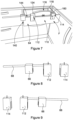
- Figure 1 shows a perspective view of a jig assembly 10 according to an embodiment of the present invention.
- the jig assembly 10 is configured for location with respect to a door D (see Figures 4 and 5 ) to which a handle is to be secured and permits the accurate indication of the positions of drill holes H in the door D to be determined without the requirement to manually measure, mark and drill the drill holes H separately.
- the jig assembly 10 comprises a first member in the form of first block 12 and a second member in the form of second block 14 which are configured to be coupled together by a spacer 16.
- the spacer 16 comprises a handle 18 corresponding to that which is to be secured to the door D, although it will be recognised that the spacer 16 may alternatively comprise the handle to be secured to the door itself following formation of the drill holes H or another spacer having dimensions corresponding to that of the handle to be secured.
- the first block 12 comprises a front portion 20 having a locator hole 22 (shown most clearly in Figure 2A ) and a back portion 24 having a locator hole 26 (shown most clearly in Figure 2B ).
- the locator holes 22, 26 form a first locator of the jig assembly 10 for indicating the position on the door D at which a first of the drill holes H should be marked and/or formed (in the illustrated embodiment the lower of the hole H in Figures 4 and 5 ).
- the first block 12 further comprises an end portion 28 of the first block 12 having a bore 30 for receiving a bolt 32 for securing the first block 12 to a first end portion 34 of the handle 18 (see Figures 2C and Figure 1 ), and a base portion 36 (shown most clearly in Figure 2D ).
- the first block 12 forms a corner piece of the jig assembly 10 and is configured to be positioned over the lower corner of the door D so that an inner surface 38 of the end portion 28 contacts a distal end surface 40 of the door D and an inner surface 42 of the base portion 36 contacts the lower surface 44 of the door D (see Figures 2C and 4 ).
- the first block 12 thus provides a location for the locator holes 22, 26 which is a fixed distance d1 from the distal end surface 40 of the door D and also a fixed distance d2 from the lower surface 44 of the door D.
- the front and back portions 20, 24 of the first block 12 are trapezoidal in shape with the distal ends of the front and back portions 20, 24 being tapered. This assists a user in correctly orienting the assembly 10 in use as shown in Figures 4 and 5 , and reduces material costs in production.
- the first block 12 is modular in that the front portion 20, back portion 24, end portion 28 and base portion 36 comprise separate components which are adapted to be coupled together.
- a modular construction increases the flexibility of construction in that the jig assembly 10 may comprise a number of end portions 28 of different thicknesses, thereby permitting the jig assembly 10 to be utilised with doors D and/or drawer fronts (see drawer front F in Figure 7 ) of different thicknesses.
- the first block 12 may be unitary in construction, with the front portion 20, back portion 24, end portion 28 and base portion 36 formed as a single piece construction.
- the second block 14 comprises a front portion 46 having a locator hole 48 and a back portion 50 having a locator hole 52.
- the locator holes 48, 52 form a second locator of the jig assembly 10 for indicating the position on the door D at which a second of the drill holes H should be marked and/or formed.
- the second block 14 further comprises an end portion 54 and, as with the first block 12, the end portion 54 of the second block 14 has a bore 56 for receiving a bolt 58 for securing the second block 14 to a second end portion 60 of the handle 18.
- the second block 14 forms a follower block of the jig assembly 10 and is configured to be positioned over the door D so that inner surface 62 of the end portion 54 contacts surface 40 of door D, the location of the second block 14 relative to the first block 12 being dependent on the length of the handle 18.
- the second block 14 also provides a location for the locator holes 48, 52 which is a fixed distance d3 from the distal end surface 40 of the door D and that the distance d3 is equal to the distance d1, thus permitting the drill holes H to be marked and/or drilled accurately at the same distance from the distal end surface 40 of the door D.
- the second block 14 is modular in that the front portion 46, back portion 50 and end portion 54 comprise separate components which are adapted to be coupled together.
- a modular construction increases the flexibility of construction in that the jig assembly 10 may comprise a number of end portions 54 of different thicknesses, thereby permitting the assembly 10 to be utilised with doors D and/or drawer fronts F (see Figure 7 ) of different thicknesses.
- a modular construction may be more appropriate for example but not exclusively by a professional user who may utilise the assembly 10 in a number of different installations.
- the second block 14 may be unitary in construction, with the front portion 46, back portion 50 and end portion 54 formed as a single piece construction.
- a unitary construction may be more appropriate for example but not exclusively by a nonprofessional user or for supply by a manufacturer.
- the jig assembly 10 is first assembled by securing the handle 18 to the first and second blocks 12, 14 using the bolts 32, 58 disposed through the respective bores 30, 56 in the end portions 28, 54 of the first and second blocks 12, 14.
- the jig assembly 10 is then able to be manipulated using the handle 18 so that the assembly 10 is positioned with respect to a door D, as shown in Figures 4 and 5 .
- the assembly 10 can be oriented in either a right hand orientation (as in Figure 4 ) or in a left hand orientation (as shown in Figure 5 ), as required by the user and can be handled using one hand, leaving the users other hand free to mark and/or form the required drill holes H.
- the jig assembly 10 is positioned over the lower corner of the door D so that the surface 38 of the first block 12 and the surface 62 of the second block 14 contact the edge 40 of the door D and so that the surface 42 of the first block 12 contacts the surface 44 of the door D.
- the locator holes 22, 26 are positioned to locate the first of the drill holes H and the locator holes 48, 52 are positioned to locate the second of the drill holes H.
- the assembly 10 permits attachment locations for securing a first item of furniture - such as a handle or the like - to a second item of furniture - such as a door, drawer front or the like - to be quickly and accurately determined and/or formed in the second item of furniture, thereby obviating the laborious requirement for repeated manual operations, saving time and reducing the risk of error and the resulting wastage which may otherwise occur, and that the assembly 10 can be quickly and easily reconfigured using different handles as spacers.
- Figure 6 shows an exemplary kit of parts comprising an assembly 10 secured to a handle 18, together with a number of alternative handles 18a, 18b, 18c, 18d and 18e which can be substituted for the handle 18.
- a jig assembly 110 according to a second embodiment of the present invention.
- the jig assembly 110 is similar to the jig assembly 10 and corresponding components are represented by like numerals incremented by 100.
- the jig assembly 110 is configured for location with respect to a drawer front F to which a handle is to be secured and comprises a first member in the block 112 and a second block 114.
- the first block 112 and the second block 114 are configured to be coupled together by a spacer 116, which in the illustrated embodiment comprises a handle 118 corresponding to that to be secured to the drawer front F.
- the first block 112 comprises a front portion 120 having a locator hole 122 and a back portion 124 having a locator hole 126.
- the first block 112 further comprises an end portion 128 having a bore 130 for receiving a bolt 132 for securing the first block 112 to a first end portion 134 of the handle 118.
- the second block 114 comprises a front portion 146 having a locator hole 148 and a back portion 150 having a locator hole 152.
- the second block 114 further comprises an end portion 154 and, as with the first block 112, the end portion 154 of the second block 114 has a bore 156 for receiving a bolt 158 for securing the second block 114 to a second end portion 160 of the handle 118.
- the locator holes 122, 126 form a first locator of the jig assembly 110 for indicating the position on the drawer front F at which a first of the drill holes H should be marked and/or formed and the locator holes 148, 152 form a second locator of the jig assembly 110 for indicating the position on the drawer front F at which a second of the drill holes H should be marked and/or formed
- both the first block 112 and the second block 114 are positioned over top surface 144 of drawer front F.
- the distance between the first block 112 and end surface 140 of the drawer front F may be altered using a positioning arrangement 64, as will be described below with reference in particular to Figures 8 and 9 and Figures 12A to 12C .
- jig assembly 110 further comprises a positioning arrangement, generally indicated by 64 - comprising a third member in the form of third block 66 - which forms the corner piece of the jig assembly 110 - and an axle 68 which is disposed through the third block 66 and which is secured to the first block 112.
- the positioning arrangement 64 is configured so that the third block 66 is axially slidable on the axle 68.
- FIGS. 12A, 12B and 12C Front, back and bottom views of the third block 66 are shown in Figures 12A, 12B and 12C .
- the third block 66 comprises a front portion 70, a back portion 72 and an end portion 74 having an inner surface 76 for engaging end surface 140 of drawer front F and inner surface 78 for engaging top surface 144 of drawer front F.
- the end portion 74 has a bore 80 through which axle 68 is disposed.
- the jig assembly 110 is initially provided with the first block 112 and positioning arrangement 64 pre-assembled, although this need not always be the case.
- the jig assembly 110 is assembled by securing the handle 118 to the first and second blocks 112, 114 using the bolts 132, 158 disposed through the respective bores 130, 156 in the end portions 128, 154 of the first and second blocks 112, 114.
- the jig assembly 110 is then able to be manipulated using the handle 118 so that assembly 10 is positioned with respect to a drawer front F, as shown in Figure 7 .
- the jig assembly 110 is positioned over the upper corner of the drawer front F so that inner surface 76 of third block 66 contacts surface 140 of the drawer front F and inner surface 78 of third block 66 contacts the surface 144 of the drawer front F; third block 66 forming a corner piece of the assembly 110.
- the locator holes 122, 126 are positioned to locate the first of the drill holes H and the locator holes 148, 152 are positioned to locate the second of the drill holes H, the drill holes H located a fixed distance d4 apart dictated by the handle 118.
- the third block 66 permits the location for the first and second locators to be adapted by sliding the third block 66 along axle 68.
- the assembly 110 is configured so that the engagement between the third block 66 and the axle 68 will remain in position unless moved by a user.
- the assembly may further a lock arrangement for securing the third block 66 to the axle 68 at a desired position, or for securing one or more of the blocks to the door D or drawer front F.
- the assembly 110 permits attachment locations for securing a first item of furniture - such as a handle or the like - to a second item of furniture - such as a door, drawer front or the like - to be quickly and accurately determined and/or formed in the second item of furniture, thereby obviating the laborious requirement for repeated manual operations, saving time and reducing the risk of error and the resulting wastage which may otherwise occur, and that the assembly 110 can be quickly and easily reconfigured using different handles as spacers.
- Figure 13 shows an exemplary kit of parts comprising an assembly 110, together with a number of handles 118, 118a, 118b and 118c.
- locator holes are provided in both the front and back portions of each of the first and second blocks, it will be recognised that locators may be provided in only one of the front or back portions of each block.
- the spacer block is sized so that the inner surfaces of the first and second blocks contact the respective front and rear surfaces of the door
- the spacer block may be sized so that the inner surfaces of the first and second blocks are spaced from the surfaces of the door. This has the benefit that any detrimental marking of the door by the assembly may be avoided or mitigated.
Landscapes
- Engineering & Computer Science (AREA)
- Mechanical Engineering (AREA)
- Architecture (AREA)
- Physics & Mathematics (AREA)
- General Physics & Mathematics (AREA)
- Civil Engineering (AREA)
- Structural Engineering (AREA)
- Drawers Of Furniture (AREA)
- Connection Of Plates (AREA)
Claims (15)
- Ensemble gabarit (10) destiné à être utilisé pour fixer un premier élément de meuble (18), tel qu'une poignée (18), à un second élément de meuble (D), l'ensemble gabarit (10) comprenant :un premier élément (12) comprenant une première pièce de repérage (22, 26) configurée pour indiquer la position d'un premier emplacement d'assemblage entre le premier élément de meuble (18) et le second élément de meuble (D) ; etun deuxième élément (14) comprenant une seconde pièce de repérage (48, 52) configurée pour indiquer la position d'un second emplacement d'assemblage entre le premier élément de meuble (18) et le second élément de meuble (D) ; etun élément d'espacement (16) ;dans lequel les premier et deuxième éléments (12, 14) sont configurés pour être fixés ensemble par l'élément d'espacement (16) qui dispose les premier et deuxième éléments (12, 14) à une distance prédéterminée l'un de l'autre de sorte à positionner les première et seconde pièces de repérage (22, 26, 48, 52) aux premier et second emplacements d'assemblage,et caractérisé en ce que l'élément d'espacement (16) comprend : le premier élément de meuble (18) qui doit être fixé au second élément de meuble (D), un élément de meuble (18) identique à celui qui doit être fixé au second élément de meuble (D), ou un élément de meuble présentant des emplacements d'assemblage correspondant à celui du premier élément de meuble (18) qui doit être fixé au second élément de meuble (D).
- Ensemble gabarit (10) selon la revendication 1, dans lequel le second élément de meuble (D) comprend une porte ou une façade de tiroir.
- Ensemble gabarit (10) selon la revendication 1 ou 2, dans lequel la première pièce de repérage (22, 26) comprend un trou de repérage ; une marque ; une ligne ; ou un profilé formé dans le premier élément (12) ou celui-ci.
- Ensemble gabarit (10) selon la revendication 1, 2 ou 3, dans lequel la première pièce de repérage (22, 26) est configurée pour permettre au premier emplacement d'assemblage d'être marqué sur le second élément de meuble et/ou formé dans celui-ci.
- Ensemble gabarit (10) selon une quelconque revendication précédente, dans lequel au moins un :du premier élément (12) comprend une partie avant (20), la partie avant (20) du premier élément (12) comprenant la première pièce de repérage (22) ;du premier élément (12) comprend une partie arrière (24),de la partie arrière (24) du premier élément (12) comprenant la première pièce de repérage (26).
- Ensemble gabarit (10) selon une quelconque revendication précédente, dans lequel au moins un du premier élément (12) et du deuxième élément (14) est de construction modulaire.
- Ensemble gabarit (10) selon l'une quelconque des revendications 1 à 5, dans lequel au moins un du premier élément (12) et du deuxième élément (14) comprend une construction unitaire.
- Ensemble gabarit (10) selon une quelconque revendication précédente, dans lequel la seconde pièce de repérage (48, 52) comprend un trou de repérage ; une marque ; une ligne, ou un profilé formé dans le deuxième élément (14) ou sur celui-ci.
- Ensemble gabarit (10) selon une quelconque revendication précédente, dans lequel la seconde pièce de repérage (48, 52) est configurée pour permettre au second emplacement d'assemblage d'être marqué sur et/ou formé dans le second élément de meuble (D).
- Ensemble gabarit (10) selon une quelconque revendication précédente, dans lequel l'ensemble gabarit (10) comprend un agencement de positionnement (64).
- Ensemble gabarit (10) selon la revendication 10, dans lequel l'agencement de positionnement (64) est configuré pour disposer le premier élément à :un emplacement donné par rapport au second élément de meuble (D) de sorte à positionner les première et seconde pièces de repérage (22, 26, 48, 52) à une distance l'une de l'autre correspondant à celle entre les premier et second emplacements d'assemblage;un emplacement distinct d'une pluralité d'emplacements distincts par rapport au second élément de meuble (D) ;un emplacement distinct d'une pluralité d'emplacements distincts par rapport à un bord du second élément de meuble (D).
- Ensemble gabarit (10) selon une quelconque revendication précédente, dans lequel l'ensemble gabarit (10) comprend un troisième élément (66) et un axe (68), le troisième élément (66) étant disposé de façon coulissante par rapport à l'axe (68).
- Kit de pièces, comprenant :
un ensemble gabarit (10) selon l'une quelconque des revendications 1 à 12 ; et au moins un élément d'espacement supplémentaire (18a, 18b, 18c, 18d, 18e). - Procédé, comprenant :la fourniture d'un ensemble gabarit (10) pour fixer un premier élément de meuble (18), tel qu'une poignée (18), à un second élément de meuble (D), l'ensemble gabarit (10) comprenant : un premier élément (12) comprenant une première pièce de repérage (22, 26) configurée pour indiquer la position d'un premier emplacement d'assemblage entre le premier élément de meuble (18) et le second élément de meuble (D) ; et un deuxième élément (14) comprenant une seconde pièce de repérage(48, 52) configurée pour indiquer la position d'un second emplacement d'assemblage entre le premier élément de meuble (18) et le second élément de meuble (D) ;la fixation des premier et deuxième éléments (12, 14) ensemble, avec un élément d'espacement (16) configuré pour disposer les premier et deuxième éléments (12, 14) à une distance prédéterminée l'un de l'autre ade sorte à positionner les pièces de repérage (22, 26, 48, 52 ) aux premier et second emplacements d'assemblage,et caractérisé en ce que l'élément d'espacement (16) comprend : le premier élément de meuble (18) qui doit être fixé au second élément de meuble (D), un élément de meuble (18) identique à celui qui doit être fixé au second élément de meuble (D), ou un élément de meuble présentant des emplacements d'assemblage correspondant à celui du premier élément de meuble (18) qui doit être fixé au second élément de meuble (D).
- Procédé selon la revendication 14, comprenant au moins une de :la disposition de l'ensemble gabarit (10) par rapport au second élément de meuble (D) ; etla formation des premier et second emplacements d'assemblage sur le second élément de meuble (D).
Applications Claiming Priority (2)
| Application Number | Priority Date | Filing Date | Title |
|---|---|---|---|
| GB1408583.1A GB2522729B (en) | 2014-05-14 | 2014-05-14 | Jig assembly |
| PCT/GB2015/051397 WO2015173559A1 (fr) | 2014-05-14 | 2015-05-13 | Ensemble gabarit |
Publications (3)
| Publication Number | Publication Date |
|---|---|
| EP3142820A1 EP3142820A1 (fr) | 2017-03-22 |
| EP3142820C0 EP3142820C0 (fr) | 2024-08-21 |
| EP3142820B1 true EP3142820B1 (fr) | 2024-08-21 |
Family
ID=51032784
Family Applications (1)
| Application Number | Title | Priority Date | Filing Date |
|---|---|---|---|
| EP15728579.2A Active EP3142820B1 (fr) | 2014-05-14 | 2015-05-13 | Ensemble gabarit et procédé |
Country Status (4)
| Country | Link |
|---|---|
| US (1) | US10286544B2 (fr) |
| EP (1) | EP3142820B1 (fr) |
| GB (1) | GB2522729B (fr) |
| WO (1) | WO2015173559A1 (fr) |
Families Citing this family (3)
| Publication number | Priority date | Publication date | Assignee | Title |
|---|---|---|---|---|
| GB2522729B (en) * | 2014-05-14 | 2016-03-30 | John Shaw | Jig assembly |
| CN111531494A (zh) * | 2020-04-30 | 2020-08-14 | 合肥余塝电子商务有限公司 | 一种组装式家具定位安装工装 |
| CN112388014B (zh) * | 2020-11-02 | 2023-09-15 | 广州欧建家居有限公司 | 一种家具橱柜铝合金拉手生产自动化加工装置 |
Family Cites Families (42)
| Publication number | Priority date | Publication date | Assignee | Title |
|---|---|---|---|---|
| GB154073A (en) | 1919-12-03 | 1920-11-25 | Bertram Harold Cope | A new or improved jig or appliance for use in the attachment of cylinder and the like locks and latches |
| US1412087A (en) | 1920-06-26 | 1922-04-11 | Ottinger Leon | Jig for forming handle holes in doors or the like |
| US2582606A (en) * | 1947-08-19 | 1952-01-15 | Riddle Don | Drawer pull gauge |
| US2821027A (en) | 1954-07-26 | 1958-01-28 | Sr Joseph John Billhimer | Adjustable rule gauge for cabinet pulls and door handles |
| US2842860A (en) | 1957-08-16 | 1958-07-15 | Elmer C Gray | Automatically centering drawer handle marking device |
| US3583823A (en) * | 1968-12-30 | 1971-06-08 | Smith Nielson Equip | Adjustable fixture for locating drawer pull holes |
| FR2240799A1 (en) * | 1973-08-13 | 1975-03-14 | Zenses Carl | U-section drill positioning clamp - has drill holes and hole for guide bar on legs and web |
| US5163233A (en) * | 1991-11-21 | 1992-11-17 | Benson Stevan G | Stud alignment tool |
| US5191718A (en) * | 1992-04-03 | 1993-03-09 | Trend Products Inc. | Masonry block spacer tool |
| US5222845A (en) | 1992-06-22 | 1993-06-29 | Goldstein Steven M | Adjustable drill guide for door handles and locks |
| US5491905A (en) * | 1994-04-26 | 1996-02-20 | Jablonski; Jeffrey C. | Apparatus for accurately spacing railing spindles |
| US5507607A (en) * | 1995-03-20 | 1996-04-16 | Ericksen; Colin | Integrated drawer side tool |
| US5590986A (en) * | 1995-05-02 | 1997-01-07 | Juang; Bor-Chang | Drill jig for locating holes to be drilled in a workpiece |
| US5807036A (en) * | 1996-10-04 | 1998-09-15 | Lostlen; Tad K. | Adjustable drill jig |
| AUPO908897A0 (en) * | 1997-09-10 | 1997-10-02 | Jovic, Radosav | Jig for fitting locks to doors |
| US20020069546A1 (en) * | 2000-12-13 | 2002-06-13 | Claxton Curtis A. E. | Adjustable tile spacing apparatus |
| US6510616B1 (en) * | 2001-01-26 | 2003-01-28 | James E. Sparkman | Adjustable template tool for stairways |
| US20020184778A1 (en) * | 2001-06-12 | 2002-12-12 | Yrazabal Joe V. | Jig for installing electrical outlet |
| US6752370B2 (en) * | 2001-07-10 | 2004-06-22 | Reyes Gonzales | Concrette curb form spacer |
| US6979299B2 (en) * | 2002-02-05 | 2005-12-27 | Zimmer Austin, Inc. | Measuring guide for use in orthopedic procedure |
| FR2838149B1 (fr) | 2002-04-05 | 2005-09-23 | Maxime Maurice Ange Patriarca | Pose poignee |
| US6796049B1 (en) * | 2003-03-18 | 2004-09-28 | Curtis A. E. Claxton | Adjustable tile spacing apparatus |
| US7003889B1 (en) | 2003-07-14 | 2006-02-28 | Michael Luciani | Template for fitting exit hardware on a door |
| US6804891B1 (en) | 2003-09-12 | 2004-10-19 | Mervin W Hurtgam | Door and drawer pull jig |
| US7252463B2 (en) | 2004-04-07 | 2007-08-07 | Andrew Valdez | Double-sided ultra-thin door marking template |
| US20060010703A1 (en) * | 2004-07-16 | 2006-01-19 | Mike Gauthier | Stud alignment jig |
| JP4186227B2 (ja) | 2004-12-28 | 2008-11-26 | 株式会社ホンダアクセス | 車両用部品取付用孔の位置決め治具 |
| US20070009335A1 (en) | 2005-07-09 | 2007-01-11 | Brewington Ophelia R | Drilling template |
| US7189035B2 (en) * | 2005-08-10 | 2007-03-13 | Miro Anthony W | Cabinet door knob pull measuring jig |
| US7377048B2 (en) * | 2005-08-24 | 2008-05-27 | Koetter Raymond E | Truss setting bracket |
| US7681324B2 (en) * | 2005-10-25 | 2010-03-23 | Hooks Sherill L | Prefabricated jig to position and align roof trusses |
| US20070101598A1 (en) * | 2005-11-08 | 2007-05-10 | Miro Anthony W | Drawer know pull measuring jig |
| US7546691B2 (en) * | 2005-11-27 | 2009-06-16 | Chester M Mackey | Adjustable workpiece positioning apparatus |
| US8112898B2 (en) * | 2006-03-27 | 2012-02-14 | Matthew Bridger Allen | Apparatus and methods for the placement of badges, ribbons and/or other items |
| NO324548B1 (no) * | 2006-04-24 | 2007-11-19 | Snorre Olsen | Maleverktoy for a merke av eller bore hull |
| US7549827B2 (en) * | 2007-01-03 | 2009-06-23 | Harry Siegfried | Hole placement guide |
| GB2460836B (en) * | 2008-06-10 | 2013-01-16 | Mark Clarke | Jig or template device |
| US8201343B2 (en) * | 2009-02-10 | 2012-06-19 | Ronald Morris | Safety stud setter |
| US9086268B2 (en) * | 2013-10-02 | 2015-07-21 | Jonathan E Jones | Concrete block spacer system |
| US9333642B2 (en) * | 2013-10-07 | 2016-05-10 | Brooks COURTNEY | Cabinet jig device with adjustable fasteners and related methods |
| GB2522729B (en) * | 2014-05-14 | 2016-03-30 | John Shaw | Jig assembly |
| US9404257B2 (en) * | 2014-07-17 | 2016-08-02 | Howard Reno | Truss and wall stabilizer |
-
2014
- 2014-05-14 GB GB1408583.1A patent/GB2522729B/en not_active Expired - Fee Related
-
2015
- 2015-05-13 EP EP15728579.2A patent/EP3142820B1/fr active Active
- 2015-05-13 US US15/310,578 patent/US10286544B2/en active Active
- 2015-05-13 WO PCT/GB2015/051397 patent/WO2015173559A1/fr not_active Ceased
Also Published As
| Publication number | Publication date |
|---|---|
| EP3142820C0 (fr) | 2024-08-21 |
| GB201408583D0 (en) | 2014-06-25 |
| US10286544B2 (en) | 2019-05-14 |
| GB2522729A (en) | 2015-08-05 |
| US20170072556A1 (en) | 2017-03-16 |
| WO2015173559A1 (fr) | 2015-11-19 |
| GB2522729B (en) | 2016-03-30 |
| EP3142820A1 (fr) | 2017-03-22 |
Similar Documents
| Publication | Publication Date | Title |
|---|---|---|
| US9333642B2 (en) | Cabinet jig device with adjustable fasteners and related methods | |
| US4257166A (en) | Adjustable drill template | |
| US8376333B2 (en) | Mechanical jig | |
| CA2211764C (fr) | Gabarit de percage reglable | |
| US20150016907A1 (en) | System for positioning and drilling in cabinet, drawer and shelf hardware | |
| US8882409B2 (en) | Shelf pin hole jig | |
| US8459906B1 (en) | Hole positioning system | |
| US8517361B2 (en) | Drawer front jig | |
| EP3142820B1 (fr) | Ensemble gabarit et procédé | |
| JPS5850805B2 (ja) | だぼによつて互いに結合される板等にだぼ孔を加工するための補助装置 | |
| US20180214960A1 (en) | Pocket hole jig | |
| US20120098183A1 (en) | Universal fence assemblies for power tool tables having multi-position stop assemblies | |
| US8641333B2 (en) | Cabinet assembly bore indexing tool and method | |
| GB2559722A (en) | Drill positioning device | |
| US12318849B1 (en) | Adjustable drill jig system and method of use | |
| US10251483B2 (en) | Drawer slide mounting locator tool and method of use | |
| AU2019275549A1 (en) | A device for locating a position for at least one hole and a hole position-locating system | |
| US10669729B2 (en) | Object placement and fastening aid | |
| CN211466710U (zh) | 一种快速定位模具 | |
| EP2923785A1 (fr) | Positionneur de forage avec visée | |
| SE533715C2 (sv) | Borrmall | |
| US20230294181A1 (en) | Machining jig for creating compound angles | |
| US10293513B2 (en) | Dado indexing jig and method of cutting a dado | |
| AU2018101473A4 (en) | Improvements relating to cutting devices to make internal keyways, splines and other shapes in blind bores and through bores | |
| WO2004069501A2 (fr) | Ensemble de perçage portatif a guides reglables |
Legal Events
| Date | Code | Title | Description |
|---|---|---|---|
| STAA | Information on the status of an ep patent application or granted ep patent |
Free format text: STATUS: THE INTERNATIONAL PUBLICATION HAS BEEN MADE |
|
| PUAI | Public reference made under article 153(3) epc to a published international application that has entered the european phase |
Free format text: ORIGINAL CODE: 0009012 |
|
| STAA | Information on the status of an ep patent application or granted ep patent |
Free format text: STATUS: REQUEST FOR EXAMINATION WAS MADE |
|
| 17P | Request for examination filed |
Effective date: 20161213 |
|
| AK | Designated contracting states |
Kind code of ref document: A1 Designated state(s): AL AT BE BG CH CY CZ DE DK EE ES FI FR GB GR HR HU IE IS IT LI LT LU LV MC MK MT NL NO PL PT RO RS SE SI SK SM TR |
|
| AX | Request for extension of the european patent |
Extension state: BA ME |
|
| DAV | Request for validation of the european patent (deleted) | ||
| DAX | Request for extension of the european patent (deleted) | ||
| RAP1 | Party data changed (applicant data changed or rights of an application transferred) |
Owner name: SUSTAIN (SCOTLAND) LIMITED |
|
| RIN1 | Information on inventor provided before grant (corrected) |
Inventor name: SHAW, JOHN |
|
| GRAP | Despatch of communication of intention to grant a patent |
Free format text: ORIGINAL CODE: EPIDOSNIGR1 |
|
| STAA | Information on the status of an ep patent application or granted ep patent |
Free format text: STATUS: GRANT OF PATENT IS INTENDED |
|
| INTG | Intention to grant announced |
Effective date: 20200716 |
|
| GRAJ | Information related to disapproval of communication of intention to grant by the applicant or resumption of examination proceedings by the epo deleted |
Free format text: ORIGINAL CODE: EPIDOSDIGR1 |
|
| STAA | Information on the status of an ep patent application or granted ep patent |
Free format text: STATUS: REQUEST FOR EXAMINATION WAS MADE |
|
| STAA | Information on the status of an ep patent application or granted ep patent |
Free format text: STATUS: EXAMINATION IS IN PROGRESS |
|
| INTC | Intention to grant announced (deleted) | ||
| 17Q | First examination report despatched |
Effective date: 20210111 |
|
| GRAP | Despatch of communication of intention to grant a patent |
Free format text: ORIGINAL CODE: EPIDOSNIGR1 |
|
| STAA | Information on the status of an ep patent application or granted ep patent |
Free format text: STATUS: GRANT OF PATENT IS INTENDED |
|
| INTG | Intention to grant announced |
Effective date: 20240321 |
|
| GRAS | Grant fee paid |
Free format text: ORIGINAL CODE: EPIDOSNIGR3 |
|
| GRAA | (expected) grant |
Free format text: ORIGINAL CODE: 0009210 |
|
| STAA | Information on the status of an ep patent application or granted ep patent |
Free format text: STATUS: THE PATENT HAS BEEN GRANTED |
|
| AK | Designated contracting states |
Kind code of ref document: B1 Designated state(s): AL AT BE BG CH CY CZ DE DK EE ES FI FR GB GR HR HU IE IS IT LI LT LU LV MC MK MT NL NO PL PT RO RS SE SI SK SM TR |
|
| REG | Reference to a national code |
Ref country code: GB Ref legal event code: FG4D |
|
| REG | Reference to a national code |
Ref country code: CH Ref legal event code: EP |
|
| REG | Reference to a national code |
Ref country code: DE Ref legal event code: R096 Ref document number: 602015089596 Country of ref document: DE |
|
| REG | Reference to a national code |
Ref country code: IE Ref legal event code: FG4D |
|
| U01 | Request for unitary effect filed |
Effective date: 20240913 |
|
| U07 | Unitary effect registered |
Designated state(s): AT BE BG DE DK EE FI FR IT LT LU LV MT NL PT RO SE SI Effective date: 20241004 |
|
| PG25 | Lapsed in a contracting state [announced via postgrant information from national office to epo] |
Ref country code: NO Free format text: LAPSE BECAUSE OF FAILURE TO SUBMIT A TRANSLATION OF THE DESCRIPTION OR TO PAY THE FEE WITHIN THE PRESCRIBED TIME-LIMIT Effective date: 20241121 |
|
| PG25 | Lapsed in a contracting state [announced via postgrant information from national office to epo] |
Ref country code: GR Free format text: LAPSE BECAUSE OF FAILURE TO SUBMIT A TRANSLATION OF THE DESCRIPTION OR TO PAY THE FEE WITHIN THE PRESCRIBED TIME-LIMIT Effective date: 20241122 Ref country code: PL Free format text: LAPSE BECAUSE OF FAILURE TO SUBMIT A TRANSLATION OF THE DESCRIPTION OR TO PAY THE FEE WITHIN THE PRESCRIBED TIME-LIMIT Effective date: 20240821 |
|
| PG25 | Lapsed in a contracting state [announced via postgrant information from national office to epo] |
Ref country code: IS Free format text: LAPSE BECAUSE OF FAILURE TO SUBMIT A TRANSLATION OF THE DESCRIPTION OR TO PAY THE FEE WITHIN THE PRESCRIBED TIME-LIMIT Effective date: 20241221 |
|
| PG25 | Lapsed in a contracting state [announced via postgrant information from national office to epo] |
Ref country code: HR Free format text: LAPSE BECAUSE OF FAILURE TO SUBMIT A TRANSLATION OF THE DESCRIPTION OR TO PAY THE FEE WITHIN THE PRESCRIBED TIME-LIMIT Effective date: 20240821 |
|
| PG25 | Lapsed in a contracting state [announced via postgrant information from national office to epo] |
Ref country code: RS Free format text: LAPSE BECAUSE OF FAILURE TO SUBMIT A TRANSLATION OF THE DESCRIPTION OR TO PAY THE FEE WITHIN THE PRESCRIBED TIME-LIMIT Effective date: 20241121 Ref country code: ES Free format text: LAPSE BECAUSE OF FAILURE TO SUBMIT A TRANSLATION OF THE DESCRIPTION OR TO PAY THE FEE WITHIN THE PRESCRIBED TIME-LIMIT Effective date: 20240821 |
|
| PG25 | Lapsed in a contracting state [announced via postgrant information from national office to epo] |
Ref country code: RS Free format text: LAPSE BECAUSE OF FAILURE TO SUBMIT A TRANSLATION OF THE DESCRIPTION OR TO PAY THE FEE WITHIN THE PRESCRIBED TIME-LIMIT Effective date: 20241121 Ref country code: PL Free format text: LAPSE BECAUSE OF FAILURE TO SUBMIT A TRANSLATION OF THE DESCRIPTION OR TO PAY THE FEE WITHIN THE PRESCRIBED TIME-LIMIT Effective date: 20240821 Ref country code: NO Free format text: LAPSE BECAUSE OF FAILURE TO SUBMIT A TRANSLATION OF THE DESCRIPTION OR TO PAY THE FEE WITHIN THE PRESCRIBED TIME-LIMIT Effective date: 20241121 Ref country code: IS Free format text: LAPSE BECAUSE OF FAILURE TO SUBMIT A TRANSLATION OF THE DESCRIPTION OR TO PAY THE FEE WITHIN THE PRESCRIBED TIME-LIMIT Effective date: 20241221 Ref country code: HR Free format text: LAPSE BECAUSE OF FAILURE TO SUBMIT A TRANSLATION OF THE DESCRIPTION OR TO PAY THE FEE WITHIN THE PRESCRIBED TIME-LIMIT Effective date: 20240821 Ref country code: GR Free format text: LAPSE BECAUSE OF FAILURE TO SUBMIT A TRANSLATION OF THE DESCRIPTION OR TO PAY THE FEE WITHIN THE PRESCRIBED TIME-LIMIT Effective date: 20241122 Ref country code: ES Free format text: LAPSE BECAUSE OF FAILURE TO SUBMIT A TRANSLATION OF THE DESCRIPTION OR TO PAY THE FEE WITHIN THE PRESCRIBED TIME-LIMIT Effective date: 20240821 |
|
| PG25 | Lapsed in a contracting state [announced via postgrant information from national office to epo] |
Ref country code: SM Free format text: LAPSE BECAUSE OF FAILURE TO SUBMIT A TRANSLATION OF THE DESCRIPTION OR TO PAY THE FEE WITHIN THE PRESCRIBED TIME-LIMIT Effective date: 20240821 |
|
| PG25 | Lapsed in a contracting state [announced via postgrant information from national office to epo] |
Ref country code: CZ Free format text: LAPSE BECAUSE OF FAILURE TO SUBMIT A TRANSLATION OF THE DESCRIPTION OR TO PAY THE FEE WITHIN THE PRESCRIBED TIME-LIMIT Effective date: 20240821 |
|
| PG25 | Lapsed in a contracting state [announced via postgrant information from national office to epo] |
Ref country code: SK Free format text: LAPSE BECAUSE OF FAILURE TO SUBMIT A TRANSLATION OF THE DESCRIPTION OR TO PAY THE FEE WITHIN THE PRESCRIBED TIME-LIMIT Effective date: 20240821 |
|
| U20 | Renewal fee for the european patent with unitary effect paid |
Year of fee payment: 11 Effective date: 20250506 |
|
| PLBE | No opposition filed within time limit |
Free format text: ORIGINAL CODE: 0009261 |
|
| STAA | Information on the status of an ep patent application or granted ep patent |
Free format text: STATUS: NO OPPOSITION FILED WITHIN TIME LIMIT |
|
| 26N | No opposition filed |
Effective date: 20250522 |
|
| REG | Reference to a national code |
Ref country code: CH Ref legal event code: H13 Free format text: ST27 STATUS EVENT CODE: U-0-0-H10-H13 (AS PROVIDED BY THE NATIONAL OFFICE) Effective date: 20251223 |
|
| PG25 | Lapsed in a contracting state [announced via postgrant information from national office to epo] |
Ref country code: CH Free format text: LAPSE BECAUSE OF NON-PAYMENT OF DUE FEES Effective date: 20250531 |
|
| PG25 | Lapsed in a contracting state [announced via postgrant information from national office to epo] |
Ref country code: MC Free format text: LAPSE BECAUSE OF FAILURE TO SUBMIT A TRANSLATION OF THE DESCRIPTION OR TO PAY THE FEE WITHIN THE PRESCRIBED TIME-LIMIT Effective date: 20240821 |
|
| PGFP | Annual fee paid to national office [announced via postgrant information from national office to epo] |
Ref country code: GB Payment date: 20260330 Year of fee payment: 12 |
|
| PG25 | Lapsed in a contracting state [announced via postgrant information from national office to epo] |
Ref country code: IE Free format text: LAPSE BECAUSE OF NON-PAYMENT OF DUE FEES Effective date: 20250513 |