EP3142932B1 - Appareil et procede pour sceller ou attacher des produits - Google Patents
Appareil et procede pour sceller ou attacher des produits Download PDFInfo
- Publication number
- EP3142932B1 EP3142932B1 EP15729262.4A EP15729262A EP3142932B1 EP 3142932 B1 EP3142932 B1 EP 3142932B1 EP 15729262 A EP15729262 A EP 15729262A EP 3142932 B1 EP3142932 B1 EP 3142932B1
- Authority
- EP
- European Patent Office
- Prior art keywords
- cell
- products
- bundle
- star wheel
- tape
- Prior art date
- Legal status (The legal status is an assumption and is not a legal conclusion. Google has not performed a legal analysis and makes no representation as to the accuracy of the status listed.)
- Active
Links
Images







Classifications
-
- B—PERFORMING OPERATIONS; TRANSPORTING
- B65—CONVEYING; PACKING; STORING; HANDLING THIN OR FILAMENTARY MATERIAL
- B65B—MACHINES, APPARATUS OR DEVICES FOR, OR METHODS OF, PACKAGING ARTICLES OR MATERIALS; UNPACKING
- B65B67/00—Apparatus or devices facilitating manual packaging operations; Sack holders
- B65B67/02—Packaging of articles or materials in containers
- B65B67/06—Manually-operable devices for closing bag necks, by applying and securing lengths of string, wire or tape
-
- B—PERFORMING OPERATIONS; TRANSPORTING
- B65—CONVEYING; PACKING; STORING; HANDLING THIN OR FILAMENTARY MATERIAL
- B65B—MACHINES, APPARATUS OR DEVICES FOR, OR METHODS OF, PACKAGING ARTICLES OR MATERIALS; UNPACKING
- B65B51/00—Devices for, or methods of, sealing or securing package folds or closures; Devices for gathering or twisting wrappers, or necks of bags
- B65B51/04—Applying separate sealing or securing members, e.g. clips
- B65B51/06—Applying adhesive tape
- B65B51/065—Applying adhesive tape to the necks of bags
-
- B—PERFORMING OPERATIONS; TRANSPORTING
- B65—CONVEYING; PACKING; STORING; HANDLING THIN OR FILAMENTARY MATERIAL
- B65B—MACHINES, APPARATUS OR DEVICES FOR, OR METHODS OF, PACKAGING ARTICLES OR MATERIALS; UNPACKING
- B65B61/00—Auxiliary devices, not otherwise provided for, for operating on sheets, blanks, webs, binding material, containers or packages
- B65B61/20—Auxiliary devices, not otherwise provided for, for operating on sheets, blanks, webs, binding material, containers or packages for adding cards, coupons or other inserts to package contents
-
- B—PERFORMING OPERATIONS; TRANSPORTING
- B65—CONVEYING; PACKING; STORING; HANDLING THIN OR FILAMENTARY MATERIAL
- B65B—MACHINES, APPARATUS OR DEVICES FOR, OR METHODS OF, PACKAGING ARTICLES OR MATERIALS; UNPACKING
- B65B61/00—Auxiliary devices, not otherwise provided for, for operating on sheets, blanks, webs, binding material, containers or packages
- B65B61/20—Auxiliary devices, not otherwise provided for, for operating on sheets, blanks, webs, binding material, containers or packages for adding cards, coupons or other inserts to package contents
- B65B61/202—Auxiliary devices, not otherwise provided for, for operating on sheets, blanks, webs, binding material, containers or packages for adding cards, coupons or other inserts to package contents for attaching articles to the outside of a container
Definitions
- the invention relates to an apparatus and method for sealing or tying products.
- the invention more specifically relates to an apparatus and method for wrapping at least an adhesive strip of tape around at least part of a bundle of products for tying them together.
- a sealer having a wheel comprising a series of slots defined in the periphery thereof, regularly spaced relative to each other along said periphery. Between each set of two adjacent slots a knife is housed in the wheel, having a cutting edge extending slightly from said periphery. Tape fed over the periphery can be cut by such cutting edge when the wheel is turned during feed through of a bag to be closed and sealed.
- a sealer having a star wheel having six identical slots provided evenly distributed around the periphery of the star wheel. Products can be hand fed though a slot in the housing of this sealer for rotating the wheel and sealing the bag.
- a sealer with a star wheel wherein the star wheel has four first slots into which the neck of a bag to be sealed can be fed, and in the middle between two adjacent first slots a second slot is provided for allowing a knife to cut tape fed over the periphery of the wheel.
- an automatic sealer having a pick and place system for adding a bag to a bundle of produce during taping of the bundle.
- the bundle can for example comprise flowers, taped together at the stems.
- the bag can for example comprise nutrients for the flowers.
- pick and place system is however complicated and costly, both in purchase and in maintenance.
- An aim of the present invention is to provide an alternative to these known apparatus and methods.
- Another aim of the present invention is to provide a method and apparatus for sealing or tying products into bundles.
- a still further aim is to provide a method and apparatus for tying fresh produce, flowers or the like natural products, especially such that items, for example containers such as, but not limited to, sachets, bags, bottles, flasks and the like can be provided with the bundle.
- An apparatus for sealing or tying products comprises a housing with at least a first tape dispenser comprising adhesive tape and binding means for binding tape from said at least one dispenser around a product or a bundle of products.
- At least one supply device is provided for supplying items to be connected to said product or bundle of products, which supply device comprises a supply arrangement.
- the binding means comprises at least one cell and an urging device for urging part of the product or bundle of products into the cell, especially towards a closed side of said cell.
- the supply arrangement is provided for supplying an item, wherein the urging device comprise holding means for holding the item provided by the supply arrangement, such that when the urging device is operated for urging the product or bundle of products into the cell the item is urged against the product or bundle of products, prior to binding the tape around the product or bundle of products in the cell.
- a method for sealing or tying products comprises leading adhesive tape over an open side of a cell of a star wheel, an adhesive side of the adhesive tape facing away from the star wheel, wherein a product or a bundle of products is pushed against the tape and into the cell, adhering at least part of the adhesive tape around at least part of the product or bundle of products, and rotating the star wheel around an axis.
- the cell with the product or bundle of products is preferably moved along a feeding station for feeding a second tape, preferably non adhesive tape, over the cell and the product or bundle, adhering to the adhesive tape.
- the method further comprises the step of tying the tape round the product or the bundle of products.
- the star wheel is rotated further and the tape is or the two adhered tapes are cut, allowing the bundle to be removed from the cell.
- the product or bundle of products is pushed into the cell at least by an urging device, wherein an item is pushed into the cell against the product or bundle of products by the urging device, wherein an item is pushed into the cell against the product or bundle of products, whereby the item is pushed into the cell by the urging device by engaging the item by a holding provision provided by the urging device.
- an item such as a container can be described to be tied by the tape with the product or products.
- Such container can for example be, but is not limited to, a sachet, bag, flask, box, bottle or any container suitable for holding content.
- other items could be tied to a product or bundle of products in the same or similar manner.
- Such items are, for the purpose of this description, also to be understood as encompassed by the description.
- first cell can be understood as meaning a first cell following the said first cell seen in a direction of rotation of the star wheel, which can be used for tying or sealing products.
- an apparatus comprises a rotating system for tying tape around a product or bundle of products, a system for urging the product or products into a cell of the rotating system and a supply system for supplying items such as bags to the urging system, such that prior to or during urging of the product or bundle of products into said cell the item is positioned against the product or bundle of products and/or to the tape, such that during tying of the tape around the product or bundle of products the item is enclosed between the tape and the product or bundle of products.
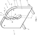
- Fig. 1 and 2 show a first exemplary embodiment of an apparatus for tying products or bundles of products.
- the apparatus 1 comprises a housing 2, at least a first tape dispenser 3 and a star wheel 4.
- a slot 5 is defined by or through the housing 2.
- the star wheel 4 extends at least partly in said slot 5.
- the housing 2 comprises a front panel 6 and back panel 7 and rests on legs 8 for providing stability and the possibility of moving the apparatus 1 to an appropriate position.
- the apparatus can thus be mobile.
- the slot 5 extends from an inlet opening 9 to an outlet opening 10.
- the outlet opening 10 can be provided between the inlet opening 9 and the legs 8.
- the outlet opening 10 opens into a hole 11 extending through the housing 2, opening to both the front 12 and back 13 thereof.
- the slot 5 is formed by cut outs in the front panel 6 and back panel 7.
- the star wheel 4 can be mounted on an axis 15, extending substantially perpendicular to the front and back 12, 13 of the housing 2, such that it can be rotated around said axis 15 within the housing 2.
- the inlet opening 9 and outlet opening 10 can be positioned such that a straight line L drawn between a mid 16 of the inlet opening 9 and a mid 17 of the outlet opening 10 extends past the axis 15 at a distance D1 there from.
- the slot 5 is curved between the inlet opening 9 and outlet opening 10 such that it passes the axis 15, a mid 18 thereof being at a distance D2 from the axis 15.
- the distance D2 can in an embodiment be larger than the distance D1. In other embodiments it can be smaller or the same.
- the star wheel 4 comprises a series of first cells 19 and a series of second cells 20.
- the position of each cell 19, 20 is for the sake of this description defined by a line J extending through the axis 15 and a mid M of a relevant cell 19, 20 at the periphery 21.
- the first cells 19 and second cells 20 can be intermittently disposed in the star wheel 4. This has to be understood as including but not necessarily limited to an arrangement of the cells 19, 20 around the periphery 21 of the star wheel 4 such that between two adjacent first cells 19 seen around the periphery 21 a second cell 20 is provided.
- Each cell 19, 20 is open to the periphery 21 of the star wheel 4 and two opposite sides 22, 23 thereof. In the embodiments shown there is the same number of first cells 19 as there are second cells 20.
- first cells 19 there can be three first cells 19 and three second cells 20.
- first cells 19 can be distributed around the periphery 21 evenly, as can the second cells 20.
- first cells 19 this means that an angle ⁇ included between two lines J through adjacent first cells 19 will be approximately 120 degrees.
- second cells 20 the angle ⁇ included between two lines J through adjacent second cells 20 will be approximately 120 degrees.
- the angles ⁇ , ⁇ will be amended accordingly, by the definition 360 degrees divided by the number of first or second cells 19, 20 respectively.
- each first cell 19 comprises a leading edge 24 and a trailing edge 25, whereas each of the second cells 20 has a leading edge 26 and a trailing edge 27, seen in a direction of rotation W of the star wheel 4.
- a direction of rotation W of the star wheel 4 is defined by rotation of the star wheel 4 around the axis 15 such that a cell 19, 20 moves from near the inlet opening 9 to near the outlet opening 20 over the shortest path of travel, along the slot 5.
- a distance D3 between a trailing edge 25 of a first cell 19 and a leading edge 26 of an adjacent second cell 20, measured along the periphery 21 of the star wheel 4 is smaller than the distance D4 between the trailing edge 27 of said second cell 20 and a leading edge 26 of the same second cell 20 and a following relevant first cell 19. In an embodiment the distance D3 can be less than half the distance between two adjacent relevant first cells 19.
- the first and second cells 19, 20 can be distributed around the periphery such that the angles ⁇ and ⁇ will be the same, but an angle Y between lines J through a first cell 19 and an adjacent trailing cell 20, that is the second cell following the first cell 19 in the direction of rotation W of the star wheel 4 is smaller than the angle ⁇ between the lines J through said second cell 20 and the following first cell 19.
- the angles a, ⁇ can be 120 degrees
- the angle Y can be between 5 and 60 degrees, more specifically between 10 and 45 degrees, for example approximately 30 degrees.
- the angle ⁇ can be about ( ⁇ - ⁇ ), which can e.g. be about 90 degrees.
- edges 24, 25, 26, 27 can extend substantially parallel to the line J extending through the relevant cell 19, 20.
- the second cells 20 can be smaller than the first cells 19.
- the first cells 19 can have a width B1 measured between the leading and trailing edge 24, 25 perpendicular to the relevant line J through the cell 19 larger than the width B2 of the second cells 20.
- the first cells 19 can be distributed such that when a one of the first cells 19 is positioned adjacent the outlet opening 10 of the slot 5, a following relevant first cell 19 is positioned adjacent the inlet opening 9 of the slot 5.
- a second cell 20 can be positioned in between, extending within the housing and/or in the slot.
- the depth X of each second cell 20 can be such that it is enclosed within the housing 2, except when passing the inlet opening 9 and/or the outlet opening 10.
- a knife carrier 28 is provided near the periphery 21, within the housing 2.
- the knife carrier 28 can be positioned near the periphery 21 of the star wheel 4 and comprises at least one knife 31 that can be moved into and out of at least one of the second cells 20, for cutting tape, as will be discussed later on.
- the knife carrier 28 is at least partly operated by rotation of the star wheel 4.
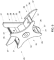
- the knife carrier 28 can, as is further elucidated in fig. 9 , be provided with a number of arms 29, extending from a central core 30, for example substantially radially. In an embodiment there can be four such arms 29. Each arm 29 can comprise a knife 31 with a cutting surface and/or teeth 32 extending substantially away from the core 30. The core 30 can be positioned on an axis 33 extending substantially parallel to the first axis 15. As can be seen especially in fig. 9 , each of the arms 29 can be provided with a first side 34 and a second side 35, the knifes 31 being provided between said sides 34, 35. Each of the first sides has a blade 36 that extends at least with a tip region 37 at a side 22 of the star wheel 4.
- an operating element 38 is provided that extends from the side 22 of the star wheel 4.
- the element 38 can for example be a notch, pin, edge, rib or any other suitable element.
- the blade 36 can be brought into contact with the operating element 38, for operating the knife carrier 28.
- a first tape dispenser 3 is provided, comprising a roll of adhesive tape 39.
- a second tape dispenser 40 is provided, for holding a second role of tape 41.
- the first tape dispenser 3 can be provided at a side of the slot 5 opposite the side of the second tape dispenser 40.
- the second tape dispenser 40 can be provided at a side of the slot at which the knife carrier 28 is also provided. Sides to the slot should be understood as to the left or right of the line L as seen in a front or rear view of the apparatus 1.
- a tautening device 42 is provided, preferably in the housing 2.
- the tautening device 42 comprises an arm 43, pivotally connected to the housing 2 in a pivot point 44.
- a side arm 45 is connected to the arm spaced apart from the pivot point 44, extending substantially in a direction away from the star wheel 4.
- the knife carrier 28 can be positioned substantially between the star wheel 4 and the arm 43.
- a spring 46 is connected between the housing 2 and the arm 43, biasing the arm towards the knife carrier 28.
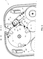
- the second side 35 of the arms 29 is substantially in the same plane as the arm 43, such that, as is shown in fig. 2 and 5 , at least one arm 29 is in contact with the arm 43 at all times.
- a pin 47 is provided, extending substantially parallel to the axis 15.
- the housing is provided with guide elements 48A, B.
- adhesive tape 39 is fed over the periphery 21 of the star wheel 4, at least past a first cell 19 near or adjacent to the inlet opening 9 of the slot 5, an adhesive side 49 of the tape 39 extending outward, away from the star wheel 4.
- a guide 50 for the second tape 41 dispensed from the second tape dispenser 40 is provided, for guiding the second tape 41 towards the periphery 21 of the star wheel 4, at a position downstream from the inlet 9.
- the second tape 41 is preferably non adhesive tape, such as but not limited to paper tape.
- the second tape preferably is easily tearable, preferably more easily that the adhesive tape 39.
- the second tape is led from the second tape dispenser 40 over the sides of the guide elements 48A, B facing away from the star wheel 4 and over the side of the pin 47 facing the star wheel 4, and then through the guide 50 towards the periphery 21 of the star wheel 4, over which it is led in a downstream direction, towards the outlet opening 10, adhered to the adhesive tape 39.
- the knife carrier 28 can be positioned in a rest position, in which the arm 43 is in contact with two arms 29 of the knife carrier 28.
- the spring 46 keeps the arm 43 in this position during rotation of the star wheel 4.
- a bundle of products such as the stems S of a bunch of flowers, schematically shown in cross section in fig. 2 directly above the star wheel, in the inlet opening 9, can be pushed into the relevant first cell 19 adjacent the inlet opening 9, in the direction F, thereby pushing the tape 39 extending over the opening of the relevant first cell 19 into the cell 19, adhering at the same time to the stems S of the flowers and dispensing tape 39.
- the star wheel 4 By pushing the stems S further in the general direction F the star wheel 4 will be rotated in the direction W, leading the stems S through the slot 5 towards the outlet opening 10.
- Tape 39 will be dispensed from the first dispenser 3. Since the second tape 41 is adhered to the first tape 39 at the downstream side of the relevant first cell 19, tape 41 will also be dispensed from the second dispenser 40. The tape will be kept taut by the tautening device 42, also keeping the knife carrier 28 in the rest position. The first tape 39 and the second tape 41 adhered thereto will thus be extended over the second cell 20 following the relevant first cell 19.
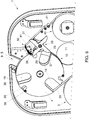
- the operating element 38 of a second cell 20 upstream adjacent the relevant first cell 19 in which the stems S extend is brought into contact with the tip region 37 of the side 36 of an arm 29 of the knife carrier 28 extending substantially into the direction of the slot 5 and inlet opening 9, as is shown in fig. 6 .
- the tip region 37 can be provided with a guide surface 51 which is curved.
- the guide surface 51 faces outward and is positioned such that upon further rotation of the star wheel 4 the operating element 38 is forced along the guide surface 51, pushing the arm 29 and especially the knife 31 into the second cell 20, bringing the knife carrier 28 and knife 31 in a working position, cutting the tapes 39 extending over the second cell 20.
- the arm 43 is pushed away from the star wheel 4, releasing to some extend the tension on the second tape 41 and allowing the knife carrier 28 to rotate further when the star wheel is rotated further in the direction W. This can bring the knife carrier back into a rest position.
- the stems S are thus enclosed between the first tape 39 extending to a high extend and preferably almost entirely around the bundle of stems S and the second tape 41 extending over a gap 52 between two parts of the first tape 39. This makes it easy to remove the tapes 39, 41 from the stems, by tearing one of the tapes, preferably the second tape 41 by pulling the two tabs 53A, B, formed on either side of the gap 52, apart.
- the position of the knife carrier 28 along the periphery 21 relative to the inlet opening 9 and the relative positions of each first cell 19 and the adjacent upstream second cell 20 defined the length 54 of the tabs 53.
- Fig. 3 and 4 , 7 and 8 disclose an alternative embodiment of an apparatus according to the description, having the same or a similar star wheel 4, first and second tape dispensers 3, 40, knife carrier 28 and tautening device 42.
- the housing is divided basically in two parts 55, 56, the slot 5 extending between and being substantially defined by facing edges 57, 58 of the two parts 55, 56.
- a carrier 59 is provided, connecting the first and second part 55, 56.
- the carrier 59 is substantially U shaped, extending substantially perpendicular to the sides 12, 13 of the housing 2, having a central element 60 and two arms 61, connecting ends of the central element 60 with the first and second part 55, 56 respectively.
- the carrier therefore extends at a distance from the slot 5.
- the apparatus 1 can be mounted with the carrier on a working surface (not shown) such that a bundle of products such as flowers with stems S can be pushed from the slot 5 through the outlet opening 10 further in the direction of movement they had when passing through the slot 5.
- the embodiments are disclosed having the slot 5 or at least the line L extending substantially vertically. It is however obviously possible to have the slot extend in any desired direction and position, for example substantially horizontally or inclined relative to a horizontal and vertical plane.
- the inlet opening 9 and first cell 19 can have corresponding widths. In another embodiment the width of the first cell 19 can differ from the inlet 9, for example smaller.
- the width B1 can for example be between 20 and 100 mm, for example between 30 and 80 mm. In an example the width B1 can be about 30 mm, about 40 mm or about 50 mm.
- the star wheel can have a diameter of any size, for example between 100 and 500 mm. In an example the star wheel can have a diameter of between 200 and 300 mm, for example about 240 to 250 mm. These sizes are only given by way of example.
- the star wheel 4 need not be circular. In an embodiment different star wheels 4 can be provided, interchangeable in the same housing.
- Different star wheels 4 can have for example but not limited to different positions of the first and second cells, different numbers of such cells, different sizes of first and/or second cells or combinations thereof, suitable for for example different sizes of bundles of products or bags or different products.
- Star wheels can have cells having for example a padding for protecting products from damage by the forces exerted thereon when being bundled, tied and/or sealed.
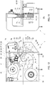
- Figs. 10 - 12 show an embodiment of an apparatus 1 according to the invention, again comprising a housing 2, at least a first tape dispenser 3 and a star wheel 4.
- a slot 5 is again defined by the housing 2, extending between an inlet 9 and an outlet 10.
- the star wheel 4 extends partly in the slot 5. Products fed through the slot 5 therefore have to engage the star wheel 4.
- the star wheel 4 is substantially the same as disclosed in the previous figures.
- star wheels 4 could be used having the first and second cells 19, 20 distributed differently, for example evenly spaced around the periphery, whereas the cells 19, 20 could all have the same sizes.
- the second cells could be omitted.
- the apparatus 1 will be discussed especially as far as it is different from the previous embodiments.
- an urging device 62 is provided, at least partly upstream of the star wheel 4.
- a support surface 63 is provided at least on one side of the slot 5, for supporting products to be tied and/or a transport device fed over the support surface 63.
- Such transport device can for example be a substantially flexible conveyer 100, which can in embodiments have a relatively soft top side for supporting the products or parts thereof. As can be seen in for example fig.
- the support surface 63 can have a wavy portion 64 next to the star wheel 4, such that when the support surface 63 extends substantially horizontally a first part 65 of the transport surface 63 next to the star wheel 4 extends higher than an axis 15 of the star wheel 4 and two adjacent parts 66 of the supporting surface 63 extend on either side of the first part 65 at a lower level.
- the structure is preferably chosen such that when a first cell 19 is open to the inlet opening 9, an edge flush with the transport surface or transport element supported thereon, another first cell is open to the outlet in a similar manner, whereas the curvature of the wavy part is such that upon rotation of the star wheel to bring the relevant cell from the inlet side to the outlet side, a bottom portion 67 of the cell follows the wavy pattern of the first part 65, thus allowing support of the product or products by the supporting surface, directly or indirectly, during such movement.
- the urging device 62 can have a central portion 68, mounted on or formed by an axis of rotation 69, preferably extending substantially parallel to the axis 15 of the star wheel 4.
- the urging device comprises three pairs of protrusions or fingers 70, extending substantially tangential to the axis 69, at even angles ⁇ of 120 degrees, between their length directions T. Of each pair the fingers 70 are spaced apart in the length direction 69L of the axis 69, such that of each pair the fingers extend on opposite sides of the star wheel 4, at least partly, as is especially clear from fig. 11 .
- the star wheel 4 and the urging device 62 have the same direction of rotation 71, in fig.
- Each finger 70 has, seen in the direction of rotation 71, a forward side forming an edge portion 72 for urging products into a cell 19 of the star wheel.
- This edge portion can be substantially straight and substantially parallel to the length direction T of the finger 70.
- the opposite, trailing side 73 of the fingers 70 can extend at a slight angle relative to the length direction T and/or the edge portion 72, and there can be a bent transition position 74 between the edge portion 72 of one finger and the trailing side 73 of the an adjacent finger 70.
- the edge portion 72 can be brought into a position in which it extends substantially parallel to and substantially at the same level as the adjacent support surface 63. In fig.
- a sensor 75 is mounted, such as for example an optical sensor, registering during use movement of products into the slot 5, over fingers 70 of the urging device 62.
- the pressing device 76 comprises two substantially parallel arms 77, extending partly on opposite sides of the star wheel 4, above the fingers 70.
- the arms 77 are mounted on a common carrier 78, mounted on an axis of rotation 79 and biased in a downward direction P, for example by one or more springs 80 and/or gravity.
- the arms 77 can rest on ends 81 of the fingers 70, such that a rotation of the urging device 62 will move the arms up and down, pivoting around the axis 79.
- the pressing device can also be an urging device.
- N could also be a different number, for example but not limited to 2 or 3.
- a knife arrangement 82 is shown, above the star wheel 4.
- a first and second dispenser 3, 40 are shown, for dispensing adhesive tape 39 and paper 41 respectively, in the same or similar manner as discussed with respect to the previous figures.
- the adhesive tape 39 is fed over the periphery of the star wheel 4, the adhesive side facing outward, from substantially a lower side 84 of the star wheel 4.
- the paper or second tape 41 is fed from the second dispenser 40 over guide and tensioning wheels 86, 87, towards an upper side 85 of the star wheel 4.
- the knife arrangement 82 can comprise a knife or blade 32, which can be movable in a linear direction K, substantially radial to the star wheel 4, into and out of a cell 20, for cutting the tape 39 or combined tapes 39, 41.
- the knife 32 can be moved by a pneumatic or hydraulic driver 88, or in another suitable way, such as but not limited to electrically or mechanically, for example coupled to the rotation of the star wheel 4.
- a device or apparatus 1 is shown, according to fig. 10 - 12 .
- Such device can be used as follows, referring also to the previous description of other embodiments.
- a product or bundle of products 51 such as flowers, vegetables, rod like elements or the like, which may or may not be enclosed at least partly in a wrap or bag, can be fed into the slot 5 from the inlet 9, over a pair of fingers 70.
- stems 90 of a bundle of flowers are shown as a bundle of products 51 to be tied.
- a control unit 91 will drive the star wheel 4 and the urging device 62 in the direction 71, such that the edge portion 72 will urge the stems 90 together and into the cell 19 of the star wheel4, against the tape 39 extending over said cell 19.
- the knife 32 will then be forced downward, into the relevant second cell 20, for cutting the tape 39 or combined tapes 39, 41, such that the tied stems 90 or at least products 51 can be removed when the star wheel is rotated further, such that the relevant cell 19 holding the stems 90 will be flush with the slot 5 again.
- For each bundle 51 to be tied the star wheel 4 and urging device 62 will be rotated over the same angle of approximately 120 degrees.
- the knife arrangement 82 can be provided with a supporting roll 92, supported on a periphery of the star wheel 4.
- the knife 32 can be biased by the driver 88 into an extended position, such that the roll 92 is forced against the periphery and that the knife 32 will automatically be forced through the tape or tapes 39, 41 when the cell 20 arrives at the roll 92 which will then be forced into said cell 20, together with the knife 32.
- the driver 88 can then retract the knife and roll 92 after the cutting.
- the knife 32 can be actively forced into the cell 20 by the driver 88, triggered by for example the control unit.
- the products can be brought into and/or held in a compact bundle during tying thereof.
- items such as containers can be provided to and bound together with products or bundles of products.
- the fingers 70 of the urging device 62 are provided with a holding provision 100, for holding an item 96, such as a bag, supplied to the urging device 62 in any suitable manner.
- the holding provision 100 in this embodiment comprises a clip 101A at a trailing side 102 of the finger or each finger of a pair of fingers 70, seen in the direction or rotation 71 of the device 62.
- An edge portion of the item 96 can be clipped by the clip 101A, such that it will rotate with the urging device 62 and will be entered into the cell 19 against a product or a bundle of products in said cell 19.
- the item 96 Upon further rotation of the urging device 62 the item 96 will be stopped from following the rotation of the urging device 62 by the product or bundle of products and will be pulled from the clip 101A, such that it can further move with the product or bundle of products 90 in said cell 19, with the star wheel 4, such that the tape or tapes will be provided around the product or bundle of products as discussed before, enclosing the item 96 between the tape or tapes and the product or bundle of products, as discussed before.
- the item 96 During the movement of the item 96 it can also be engaged by the tape at a different moment, for example during transfer into the cell.
- the items 96 can for example be bags which may be supplied individually to the holding provision 100, or may be provided as a strip and cut from such strip during the positioning thereof in the holding provision 100.
- FIG. 14 schematically an embodiment is shown of an apparatus 1, for example according to fig. 12 , combined with a supply device 95 for feeding containers or other items 96 to the tape 39 between the first dispenser 3 and the slot 5.
- the device 95 comprises a conveyer 98 on which a container or item 96 or preferably a series or strip of such items 96 and supplied towards the urging device 62 in the direction F 1 .
- the item 96 is fed directly into the holding provision 100, such as into the clip 101A.
- the end 98A of the conveyer 98 can extend between the fingers 70 of the urging device 62 for feeding the items into the holding provision 100.
- the tack of the urging device and conveyer 98 can be controlled for properly positioning one item in each holding provision.
- the conveyer 98 can conveniently be positioned just below the surface over which the product or bundles of products are supplied towards the star wheel 4.
- a product or bundle of products 51 such as the stems 90 are forced into the relevant cell 19, pushing the tape 39 into the cell, the container or item 96 will be enclosed between the tape 39 and the product or bundle of products 51, such that it will be tied to the product or bundle 51 simultaneously.
- An example of a container or item 96 can be, but is not limited to a bag, sachet, flask, bottle, leaflet, gift or the like.
- bundling flowers the item 96 can for example be a sachet containing nutrition or fertiliser.
- packaging produce the item can for example be additives to be used with the produce, such as but not limited to herbs, spices or the like.
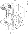
- a further embodiment is shown of an apparatus 1 for binding products or bundles of products, such as but not limited to bundles of flowers or fresh produce, similar to the embodiment of e.g. fig. 10 - 14 , again provided with a supply device 95 comprising a supply arrangement for feeding items to be combined with said products or bundles of products to be bound.
- the item to be fed is a sachet 96, especially a sachet with nutrients for flowers with which they are to be combined.
- the urging device 62 again positioned at least partly upstream of the star wheel 4, has a series of pairs of protrusions or fingers 70 extending from a central part 68, rotatable on an axis 69.
- This axis extends substantially parallel to the axis 15 of rotation of the star wheel.
- a first finger 70A extends in a plane on and substantially parallel to a first side of the star wheel 4
- the second finger 70B of each pair extends in a plane on and substantially parallel to an opposite second side of the star wheel 4.
- Each finger 70 is provided with at least part of a holding provision 100 for temporarily holding an item 96 to be supplied to the product or bundle of products 51 to be bound.
- the holding provision 100 is provide such that upon urging a product or a bundle of products into a cell 19 the item is transferred into the same cell 19 and. Preferably, urged against the product or bundle of products then urged into or contained in the cell 19. Thus the items 96 can automatically be fed to the product or bundle of products in a correct manner.
- the holding provision 100 is preferably such that when the item is brought into the cell and pushed against the product or bundle provided therein, upon further rotation of the urging device the item is released automatically from the holding provision 100.
- each finger 70A, 70B is provided with a slot 101 forming a relevant part of a holding provision 100. Seen in the direction of rotation 71 of the urging device 62 the slots 101 are provided in the trailing edges 102 of the fingers 70. Each slot 101 has a holding portion 103 and a mouth 104 opening into said side edge 102. The holding portion 103 is wider than the mouth 104, such that one either side of the mouth 104 an edge portion 105A, B is provided. In the embodiment shown each edge portion 105A, B is provided with an angled surface, such that the holding portion 103 narrows towards the mouth 104. Seen from a side the two slots 101 in a pair of fingers 70 are in line with each other and preferably identical in shape and dimensions.
- An item such as a sachet 96 can be placed in the holding provisions 100 in a pair of fingers 70, as shown in fig. 15 - 17 , such that two spaced apart parts of the item 96 rest in the relevant holding portions 103 of the slots 101, for example with opposite ends of the item 96.
- an item 96 can be inserted from a side of the urging device 62, for example when a pair of fingers 70 extends substantially horizontally, the mouths 104 of the relevant slots facing downward.
- a pair of fingers 70 extends substantially horizontally, the mouths 104 of the relevant slots facing downward.
- a previously inserted item 96B can have been carried by the urging device 62 towards the star wheel 4, especially towards and into a cell 19 thereof, into which cell a product or bundle of products is fed, urged by leading edges 72 of fingers 70.
- the fingers 70 are moved alongside opposite sides of the star wheel 4, whereas the item 96 is prevented from further movement when abutting a product or bundle of products and/or a wall of the cell 19, which means that the item will be pushed out of the holding provisions 100 through the mouths 104.
- the following item 96A is lifted and rotated towards the star wheel 4, especially the following cell 19 since the star wheel 4 will also rotate.
- the pressing device 76 especially arms 77 thereof can also move between the fingers 70, pressing the item 96 further into the cell 19.
- a supply device comprising a conveyer system 106 having a feeding direction F 1 substantially parallel to the axis 69 of the urging device 62, contrary to the embodiment of fig. 14 in which said feeding direction F 1 was shown substantially perpendicular to said axis 69.
- the conveyer system is 106 is designed for feeding sachets or the like relatively flat, possibly relatively flexible items, for example filled with nutrients.
- Such conveyer systems are known in the art of conveying.
- the conveyers system as shown comprises a lower and an upper endless conveyer belt 107, 108, in close proximity in a feeding area 109.
- a first pair of rollers 110 is provided at a feeding end 112, a second pair or rollers 111 is provided at an outlet end 113.
- the outlet end is in close proximity to a side of the urging device 62, such that when the belts 107, 108 are driven towards the outlet end 113, items 96 leaving the outlet end 113 are moved directly into the holding provisions 100 of an adjacent pair of fingers 70.
- a stop 115 can be provided on the opposite side of the urging device, preventing the item from flying through the holding provisions, such that the item will be properly fitted in the holding portions 103.
- the items 96 can be fed into the conveyer set system between the conveyer belts 107, 108 in any suitable way, mechanically or manually.
- the items such as sachets 96 can be fed in single file, as separate items 96. Alternatively they can be fed as a string of interconnected items, such as a string of sachets 96, from which string the item in the holding provisions can be severed, for example directly prior to or after feeding it into said holding provisions 100.
- a stationary table could be provided, alongside which the fingers can move.
- An item inserted into the holding provisions could temporarily be supported and/or guided by the surface of said table. This could aid in proper positioning of the items, especially when they are relatively flexible.
- the items could be fed into the holding provisions in a different direction, for example in a direction substantially perpendicular to the axis 69, as shown in fig. 14 .
- a feeding mechanism such as a lift could be used with which a single item such as a sachet is pushed upward in fig. 16 into the holding provisions 100, through the mouths 104.
- the item 96 may be relatively flexible, such that it can bend, at least enough for it to be able to be pushed out of the holding provisions through the mouths, but stiff enough to be able to be carried on the edge portions 105A, B. If for example a stiffer item should be fed, the holding provisions could be provided with for example resiliently flexible edge portions 105A and/or B, such that these could bend away for allowing the item to pass into or out of the holding portion 104, but able to carry the item one inserted.
- edge portions 105A and/or B could be provided which are movable relative to the fingers 70 such that the can be pushed away when an item is entered into or moved out of the holding provisions 100, but are biased into a position in which they can carry the item in the holding provisions 100.
- Such moving of such edge portions 105A and/or B could be provided for by movement of the item 96 and/or could be actively forced by for example mechanical means provided along the path of travel of the fingers 70, such as urging cams or the like.
- the holding provisions could be provided on a leading edge 72 of the urging device 62 in stead of at the trailing edge 102.
- a star wheel 4 can have a width measured parallel to the axis 15 which is comparable to a width in the same direction of items 96 to be supplied, so as to provide an even better support and/or preventing possible collision with for example urging means and/or pressing means when available.
- At least one of the knife arrangement or knife carrier, the star wheel and the urging device and/or pressing device, and/or at least one dispenser 3, 40 could be connected to a counter, registering the number of revolutions or cutting actions during a period, which will be indicative for the number of products or bundles of products that have been tied during that period. This information can be read directly from the counter or could be transferred to another location, for example by wireless, sms or the like.
- the star wheel can be driven differently, for example through a step motor engaging the axis 15 or by the feeding and/or discharging means.
- the knife carrier can be made differently, for example as an arm extending partly in the outlet opening 10, such that when the products are moved through the outlet opening the knife 31 is forced into a second cell 20, cutting loose the stems S.
- a star wheel in the form of an endless star belt, formed as a belt having a series of cells in an outwardly facing surface, guided over at least two end wheels, such that a series of cells 19, 20 is fed along the guide surface, allowing a series of bundles to be handled at the same time.
- Means can be provided to print information on and/or in the tape and/or the foil strip, such as sealing date, expiration date of the product, packing apparatus identification, advertisements or other information.
- the width of the strip of tape 39 is about the same as the width of the tape 41.
- the second tape 41 can have a greater with in order to provide further information, such as user information, warranties and other communications.
- the urging means can be designed differently, for example moving substantially linearly.
- a transport belt of conveyer could be provided on both sides of the star wheel, or on only one side, and could be provided with elements for urging the products into a cell of the star wheel.
- the pressing device could also be designed differently, for example a flexible element extending alongside one or both of the sides of the star wheel, at an upper side of the cells 19 when opening towards the inlet 9 and/or outlet 10, for holding the products at a lower side 67 of the cell 19.
Landscapes
- Engineering & Computer Science (AREA)
- Mechanical Engineering (AREA)
- Specific Conveyance Elements (AREA)
- Package Closures (AREA)
Claims (15)
- Appareil destiné à sceller ou attacher des produits, comprenant un boîtier (2) avec au moins un premier distributeur de ruban (3) comportant du ruban adhésif et des moyens de liage destinés à lier le ruban provenant dudit distributeur (3), au nombre d'au moins un, autour d'un produit ou d'un paquet de produits (51) ; dans lequel au moins un dispositif d'alimentation (95) est prévu pour fournir des objets (96) devant être reliés audit produit ou au paquet de produits (51) ; dans lequel le moyen de liage comporte au moins une alvéole (19) et un dispositif de poussée (62) destiné à pousser une partie du produit ou du paquet de produits (51) dans l'alvéole (19), en particulier en direction d'un côté fermé de l'alvéole (19), caractérisé en ce que le dispositif de poussée (62) comprend au moins un moyen de maintien (100) pour maintenir un objet (96) amené par le dispositif d'alimentation (95), de manière à ce que, lorsque le dispositif de poussée (62) est actionné pour pousser le produit ou le paquet de produits (51) dans l'alvéole (19), l'objet (96) soit poussé contre le produit ou le paquet de produits (51), avant le liage du ruban autour du produit ou du paquet de produits (51), dans l'alvéole (19).
- Appareil selon la revendication 1, dans lequel le moyen de liage comprend une roue en étoile (4), une fente (5) étant définie par ou à travers le boîtier (2), la roue en étoile (4) s'étendant au moins en partie dans ladite fente (5), la roue en étoile (4) comportant une série de premières alvéoles (19) et une série de deuxièmes alvéoles (20), les premières et les deuxièmes alvéoles (19, 20) étant disposées de façon intermittente dans la roue en étoile (4), chaque alvéole (19, 20) étant ouverte vers une périphérie de la roue en étoile (4) et deux côtés opposés de celle-ci.
- Appareil selon la revendication 1 ou 2, dans lequel le dispositif de poussée (62) comprend une partie centrale (68) avec au moins une saillie (70) qui s'étend à partir de la partie centrale (68), de manière à ce que, après la rotation de la partie centrale (68), la saillie (70), au nombre d'au moins une, soit tournée le long de l'alvéole (19), au nombre d'au moins une, transférant ainsi l'objet dans ladite alvéole (19).
- Appareil selon l'une quelconque des revendications 1 à 3, dans lequel le moyen de liage comprend une roue en étoile (4) pouvant être mise en rotation autour d'un axe (15), une fente (5) étant définie par ou à travers le boîtier (2), la roue en étoile (4) s'étendant au moins en partie dans ladite fente (5), la roue en étoile (4) comportant une série de premières alvéoles (19) prévues à intervalles réguliers le long d'une périphérie de la roue en étoile, chaque alvéole (19) étant ouverte vers une périphérie de la roue en étoile (4) et deux côtés opposés de celle-ci, le dispositif de poussée (62) comprenant une partie centrale (68) pouvant tourner autour d'un axe (69) parallèle à l'axe (15) de la roue en étoile (4), une série de saillies (70) étant prévues, qui s'étendent à partir de la partie centrale (68), le long d'au moins un côté de la roue en étoile (4), en particulier le long desdits deux côtés opposés de ladite roue en étoile (4), les moyens de maintien (100) étant prévus à l'endroit des saillies (70).
- Appareil selon la revendication 4, dans lequel une série de paires d'une première et d'une deuxième saillie (70) est prévue sur la partie centrale (68), les premières saillies (70) s'étendant dans un plan s'étendant le long d'un premier côté de la roue en étoile (4), et les deuxièmes saillies (70) s'étendant dans un plan s'étendant le long d'un deuxième côté opposé de la roue en étoile (4).
- Appareil selon la revendication 5, dans lequel, pendant le transfert, un objet (96) repose sur les deux saillies (70) d'une paire, de manière à ce qu'une partie de l'objet (96) s'étendant entre les saillies (70) soit libre pour une entrée en contact.
- Appareil selon l'une quelconque des revendications 4 à 6, dans lequel l'agencement d'alimentation comprend un distributeur d'objets (95) présentant un sens d'alimentation principal qui est sensiblement parallèle à l'axe de rotation du dispositif de poussée (62), en vue de distribuer des objets (96) dans le moyen de maintien (100).
- Appareil selon l'une quelconque des revendications 4 à 6, dans lequel l'agencement d'alimentation comprend un distributeur d'objets (95) présentant un sens d'alimentation principal qui est sensiblement perpendiculaire à l'axe (69) de rotation du dispositif de poussée (62), en vue de distribuer des objets (96) dans le moyen de maintien (100).
- Appareil selon l'une quelconque des revendications précédentes, dans lequel l'agencement d'alimentation comprend un dispositif de transport (98), tel qu'un transporteur.
- Appareil selon l'une quelconque des revendications précédentes, dans lequel le dispositif d'alimentation (95) est prévu de manière telle que les objets qui adhèrent au ruban soient enfermés entre la face adhésive du ruban et le produit ou le paquet de produits (51) lorsque le ruban est ensuite collé audit produit ou au paquet de produits (51).
- Appareil selon l'une quelconque des revendications précédentes, dans lequel est prévu un dispositif de commande (91) qui synchronise au moins le fonctionnement du moyen de liage et du dispositif d'alimentation (95).
- Procédé destiné à sceller ou attacher des produits, selon lequel un ruban adhésif est amené sur un côté ouvert d'une alvéole (19) d'une roue en étoile (4), la face adhésive du ruban adhésif étant tournée vers le côté opposé à la roue en étoile (4) ; selon lequel un produit ou un paquet de produits (51) est poussé contre le ruban et dans l'alvéole (19), en faisant adhérer au moins une partie du ruban adhésif autour d'au moins une partie du produit ou du paquet de produits (51), et en faisant tourner la roue en étoile (4) autour d'un axe (15) ; selon lequel l'alvéole (19) avec le produit ou le paquet de produits (51) est de préférence déplacée le long d'un poste de distribution en vue de distribuer un deuxième ruban, de préférence un ruban non adhésif, sur l'alvéole (19) et le produit ou le paquet de produits (51), en le faisant adhérer au ruban adhésif et en attachant le ruban autour du produit ou du paquet de produits (51) ; selon lequel la roue en étoile (4) est tournée davantage et le ruban ou les deux rubans collés sont coupés, permettant ainsi de retirer le paquet (51) de l'alvéole (19) ; selon lequel le produit ou le paquet de produits (51) est poussé dans l'alvéole (19) au moins par un dispositif de poussée (62) ; selon lequel un objet (96) est poussé dans l'alvéole (19), contre le produit ou le paquet de produits (51), l'objet étant poussé dans l'alvéole par le dispositif de poussée, en amenant l'objet (96) en prise avec un moyen de maintien (100) prévu sur le dispositif de poussée (62).
- Procédé selon la revendication 12, selon lequel l'objet est enfermé au moins en partie entre le produit ou le paquet de produits et le ruban.
- Procédé selon la revendication 12 ou 13, selon lequel le produit ou le paquet de produits (51) est poussé dans l'alvéole (19) par le dispositif de poussée (62) et/ou un dispositif de pression (76) ; selon lequel, avant de pousser le produit ou le paquet de produits (51) dans l'alvéole (19), un objet est placé (96) sur le dispositif de poussée (62), de façon à ce qu'il soit transporté en direction de l'alvéole (19) par le dispositif de poussée (62).
- Utilisation d'une scelleuse (1) avec une roue en étoile (4), un distributeur de ruban adhésif et un distributeur de ruban pour un deuxième ruban, plus facilement déchirable que le ruban adhésif, à des fins de liage de produits (51), en particulier de produits agricoles ou horticoles frais, sachant que le ruban adhésif est distribué par le distributeur et enroulé autour d'au moins une partie d'un paquet de produits (51) en utilisant la roue en étoile (4), à la suite de quoi un deuxième ruban est collé sur le ruban adhésif, de manière à ce que les extrémités du ruban adhésif soient recouvertes par le deuxième ruban et ne collent pas l'une à l'autre, le paquet de produits (51) étant poussé dans l'alvéole (19) par un dispositif de poussée (62), un objet (96) étant poussé dans l'alvéole (19) par le dispositif de poussée (62), contre le produit ou le paquet de produits (51), sachant qu'avant de pousser le produit ou le paquet de produits dans l'alvéole, l'objet est placé sur le dispositif de poussée, le dispositif de poussée (62) entrant en prise avec l'objet (96) par un moyen de maintien (100) prévu sur le dispositif de poussée (62), de façon à ce qu'il soit transporté en direction de l'alvéole par le dispositif de poussée.
Applications Claiming Priority (2)
| Application Number | Priority Date | Filing Date | Title |
|---|---|---|---|
| NL2012818A NL2012818B1 (en) | 2014-05-15 | 2014-05-15 | Apparatus and method for sealing or tying products. |
| PCT/NL2015/050347 WO2015174845A1 (fr) | 2014-05-15 | 2015-05-15 | Appareil et procede pour sceller ou attacher des produits |
Publications (2)
| Publication Number | Publication Date |
|---|---|
| EP3142932A1 EP3142932A1 (fr) | 2017-03-22 |
| EP3142932B1 true EP3142932B1 (fr) | 2018-02-14 |
Family
ID=51136724
Family Applications (1)
| Application Number | Title | Priority Date | Filing Date |
|---|---|---|---|
| EP15729262.4A Active EP3142932B1 (fr) | 2014-05-15 | 2015-05-15 | Appareil et procede pour sceller ou attacher des produits |
Country Status (5)
| Country | Link |
|---|---|
| US (1) | US10807754B2 (fr) |
| EP (1) | EP3142932B1 (fr) |
| ES (1) | ES2662893T3 (fr) |
| NL (1) | NL2012818B1 (fr) |
| WO (1) | WO2015174845A1 (fr) |
Families Citing this family (2)
| Publication number | Priority date | Publication date | Assignee | Title |
|---|---|---|---|---|
| NL2018897B1 (en) * | 2017-05-11 | 2018-11-15 | Duoseal Automatics B V | Apparatus and method for sealing or tying products |
| US12043478B2 (en) * | 2022-05-06 | 2024-07-23 | Gustavo Leon | Waste container with integrated bag sealer |
Family Cites Families (31)
| Publication number | Priority date | Publication date | Assignee | Title |
|---|---|---|---|---|
| US2841935A (en) * | 1956-03-12 | 1958-07-08 | Derby Sealers Inc | Bag-tying machine |
| US2906425A (en) * | 1958-10-02 | 1959-09-29 | Ever Ready Calendar Mfg Compan | Label inserting apparatus |
| US3031368A (en) * | 1961-02-08 | 1962-04-24 | Automatic Spot Taping Machine | Taping machine |
| US3242850A (en) * | 1962-11-14 | 1966-03-29 | Republic Steel Corp | Adhesive tape applying mechanism for bundling machines |
| USRE28170E (en) * | 1973-07-09 | 1974-09-24 | Device for tying ends of bags | |
| DE2949252A1 (de) * | 1979-12-07 | 1981-06-11 | Focke & Co, 2810 Verden | Verfahren und vorrichtung zum verpacken von zigaretten o.dgl. |
| JPS58149228A (ja) * | 1982-02-19 | 1983-09-05 | 株式会社大生機械 | 包装用結束装置 |
| US4561234A (en) * | 1982-12-02 | 1985-12-31 | California Artichoke And Vegetable Growers Corp. | Product tying machine |
| NL8500050A (nl) * | 1985-01-09 | 1986-08-01 | Nicolaas Van Rosendal | Inrichting voor het aanbrengen van een sluitstrip, en een cassette daarvoor. |
| JPS62251319A (ja) * | 1986-04-24 | 1987-11-02 | ワイケイケイ株式会社 | 長尺製品の巻付結束仕上方法およびその装置 |
| JPH0350984Y2 (fr) * | 1986-05-13 | 1991-10-31 | ||
| NL8902097A (nl) | 1989-08-18 | 1991-03-18 | Henkel Nederland | Zaksluiter. |
| NL9002536A (nl) * | 1990-11-20 | 1992-06-16 | Henkel Nederland | Zaksluiter. |
| NL9202118A (nl) * | 1992-12-07 | 1994-07-01 | Novem Trading Int Bv | Inrichting voor het aanbrengen van een sluitstrip. |
| US5410861A (en) * | 1993-04-13 | 1995-05-02 | Medlock; Harold G. | Apparatus for banding bunched articles |
| ITBO940293A1 (it) * | 1994-06-27 | 1995-12-27 | Gd Spa | Metodo e dispositivo per l'alimentazione di assiemi colletto-coupon ad una linea di incarto di una macchina impacchettatrice per la |
| NL1000546C2 (nl) * | 1995-06-12 | 1996-12-16 | Novem Int Bv | Systeem voor het omsnoeren van voorwerpen. |
| US5782067A (en) * | 1996-06-28 | 1998-07-21 | Free-Flow Packaging International, Inc. | Bag sealer and cutter for use in packaging loose fill packaging materials |
| US5875618A (en) * | 1996-10-28 | 1999-03-02 | Wella Aktiengesellschaft | Hand-held device for bundling elongated objects |
| IT1304784B1 (it) * | 1998-12-15 | 2001-03-29 | Gd Spa | Metodo per la realizzazione di pacchetti di sigarette ed impianto perl'attuazione di tale metodo. |
| US6508048B2 (en) * | 2000-12-08 | 2003-01-21 | A. J. Panneri Enterprises, Inc. | Banding fixture |
| US6772577B2 (en) * | 2000-12-08 | 2004-08-10 | A. J. Panneri Enterprises, Inc. | Branding fixture structures |
| ITBO20030561A1 (it) * | 2003-09-30 | 2005-04-01 | Gd Spa | Macchina impacchettatrice |
| EP1571086A1 (fr) * | 2004-03-05 | 2005-09-07 | Kba-Giori S.A. | Système pour envelopper des produits empilés et procédé |
| US6971218B1 (en) * | 2004-06-01 | 2005-12-06 | Clayton Huckaba | Method and apparatus for banding a wrapped bundle of articles |
| US8646247B2 (en) * | 2009-09-28 | 2014-02-11 | Burford Corp. | Method for applying tape closure to a bag |
| US8739500B2 (en) * | 2010-08-18 | 2014-06-03 | Hsiu-Man Yu Chen | Bag neck sealer |
| US20120046152A1 (en) * | 2010-08-18 | 2012-02-23 | Hsiu-Man Yu Chen | Bag neck sealer |
| US8622440B2 (en) * | 2010-10-05 | 2014-01-07 | Ideal Industries, Inc. | Knot tying device and cartridge system for providing tying filament thereto |
| NL2005627C2 (en) * | 2010-11-04 | 2012-05-07 | Duoseal Automatics B V | Apparatus and method for sealing or tying products. |
| US9786416B1 (en) * | 2016-03-28 | 2017-10-10 | Te Connectivity Corporation | Tape dispensing tool |
-
2014
- 2014-05-15 NL NL2012818A patent/NL2012818B1/en not_active IP Right Cessation
-
2015
- 2015-05-15 WO PCT/NL2015/050347 patent/WO2015174845A1/fr not_active Ceased
- 2015-05-15 ES ES15729262.4T patent/ES2662893T3/es active Active
- 2015-05-15 EP EP15729262.4A patent/EP3142932B1/fr active Active
- 2015-05-15 US US15/309,814 patent/US10807754B2/en active Active
Also Published As
| Publication number | Publication date |
|---|---|
| US20170144789A1 (en) | 2017-05-25 |
| WO2015174845A1 (fr) | 2015-11-19 |
| ES2662893T3 (es) | 2018-04-10 |
| EP3142932A1 (fr) | 2017-03-22 |
| US10807754B2 (en) | 2020-10-20 |
| NL2012818B1 (en) | 2016-03-02 |
Similar Documents
| Publication | Publication Date | Title |
|---|---|---|
| EP3401226B1 (fr) | Appareil et procédé pour sceller ou lier des produits et utilisation de cet appareil | |
| US9339998B2 (en) | Apparatus and method for sealing or tying products | |
| CN102227352B (zh) | 用于制造束条包装的方法和装置以及束条包装 | |
| US9469425B2 (en) | Apparatus and method for sealing or tying products | |
| CN104718067B (zh) | 一种制作包装用纸箱的方法以及采用此方法的装置 | |
| EP2419337B1 (fr) | Dispositif pour emballer un produit dans une enveloppe | |
| CN105492327B (zh) | 用可伸缩膜包裹物品的冷加工收缩包裹机及相关方法 | |
| CN105916774B (zh) | 改进的捆扎装置 | |
| CN113272228A (zh) | 用于将薄膜包装在物品周围的包装机 | |
| US10807754B2 (en) | Apparatus and method for sealing or tying products | |
| CN209064521U (zh) | 包装机和包装堆叠体 | |
| AU2007278818B2 (en) | Two-in-one bagger system | |
| JP5155594B2 (ja) | 一連の編集製品をプラスチックフィルムにより包装する自動機械及び方法 | |
| NL2007689C2 (en) | Apparatus and method for bundling, sealing and/or tying products. | |
| NL2003098C2 (en) | APPARATUS AND METHOD FOR SEALING OR TYING PRODUCTS. | |
| US3237370A (en) | Packaging machine | |
| CN1970390B (zh) | 用于包装物品的方法和装置 | |
| US1522545A (en) | Wrapping machine | |
| US3269078A (en) | Method of packaging articles | |
| EP3805124A1 (fr) | Procédé de fabrication d'un sac en papier, machine pour la réalisation de ce procédé et sac en papier obtenu par ce procédé | |
| WO2004071753A1 (fr) | Procede et appareil pour appliquer des etiquettes sur des objets |
Legal Events
| Date | Code | Title | Description |
|---|---|---|---|
| PUAI | Public reference made under article 153(3) epc to a published international application that has entered the european phase |
Free format text: ORIGINAL CODE: 0009012 |
|
| 17P | Request for examination filed |
Effective date: 20161128 |
|
| AK | Designated contracting states |
Kind code of ref document: A1 Designated state(s): AL AT BE BG CH CY CZ DE DK EE ES FI FR GB GR HR HU IE IS IT LI LT LU LV MC MK MT NL NO PL PT RO RS SE SI SK SM TR |
|
| AX | Request for extension of the european patent |
Extension state: BA ME |
|
| DAV | Request for validation of the european patent (deleted) | ||
| DAX | Request for extension of the european patent (deleted) | ||
| GRAP | Despatch of communication of intention to grant a patent |
Free format text: ORIGINAL CODE: EPIDOSNIGR1 |
|
| INTG | Intention to grant announced |
Effective date: 20171017 |
|
| RIN1 | Information on inventor provided before grant (corrected) |
Inventor name: AARTS, GUIDO MAURINUS ADRIANA MARIA |
|
| GRAS | Grant fee paid |
Free format text: ORIGINAL CODE: EPIDOSNIGR3 |
|
| GRAA | (expected) grant |
Free format text: ORIGINAL CODE: 0009210 |
|
| AK | Designated contracting states |
Kind code of ref document: B1 Designated state(s): AL AT BE BG CH CY CZ DE DK EE ES FI FR GB GR HR HU IE IS IT LI LT LU LV MC MK MT NL NO PL PT RO RS SE SI SK SM TR |
|
| REG | Reference to a national code |
Ref country code: GB Ref legal event code: FG4D |
|
| REG | Reference to a national code |
Ref country code: CH Ref legal event code: EP |
|
| REG | Reference to a national code |
Ref country code: IE Ref legal event code: FG4D |
|
| REG | Reference to a national code |
Ref country code: DE Ref legal event code: R096 Ref document number: 602015008049 Country of ref document: DE Ref country code: AT Ref legal event code: REF Ref document number: 969689 Country of ref document: AT Kind code of ref document: T Effective date: 20180315 |
|
| REG | Reference to a national code |
Ref country code: ES Ref legal event code: FG2A Ref document number: 2662893 Country of ref document: ES Kind code of ref document: T3 Effective date: 20180410 |
|
| REG | Reference to a national code |
Ref country code: FR Ref legal event code: PLFP Year of fee payment: 4 |
|
| REG | Reference to a national code |
Ref country code: NL Ref legal event code: FP |
|
| REG | Reference to a national code |
Ref country code: AT Ref legal event code: MK05 Ref document number: 969689 Country of ref document: AT Kind code of ref document: T Effective date: 20180214 |
|
| PG25 | Lapsed in a contracting state [announced via postgrant information from national office to epo] |
Ref country code: NO Free format text: LAPSE BECAUSE OF FAILURE TO SUBMIT A TRANSLATION OF THE DESCRIPTION OR TO PAY THE FEE WITHIN THE PRESCRIBED TIME-LIMIT Effective date: 20180514 Ref country code: HR Free format text: LAPSE BECAUSE OF FAILURE TO SUBMIT A TRANSLATION OF THE DESCRIPTION OR TO PAY THE FEE WITHIN THE PRESCRIBED TIME-LIMIT Effective date: 20180214 Ref country code: LT Free format text: LAPSE BECAUSE OF FAILURE TO SUBMIT A TRANSLATION OF THE DESCRIPTION OR TO PAY THE FEE WITHIN THE PRESCRIBED TIME-LIMIT Effective date: 20180214 Ref country code: CY Free format text: LAPSE BECAUSE OF FAILURE TO SUBMIT A TRANSLATION OF THE DESCRIPTION OR TO PAY THE FEE WITHIN THE PRESCRIBED TIME-LIMIT Effective date: 20180214 Ref country code: FI Free format text: LAPSE BECAUSE OF FAILURE TO SUBMIT A TRANSLATION OF THE DESCRIPTION OR TO PAY THE FEE WITHIN THE PRESCRIBED TIME-LIMIT Effective date: 20180214 |
|
| PG25 | Lapsed in a contracting state [announced via postgrant information from national office to epo] |
Ref country code: GR Free format text: LAPSE BECAUSE OF FAILURE TO SUBMIT A TRANSLATION OF THE DESCRIPTION OR TO PAY THE FEE WITHIN THE PRESCRIBED TIME-LIMIT Effective date: 20180515 Ref country code: LV Free format text: LAPSE BECAUSE OF FAILURE TO SUBMIT A TRANSLATION OF THE DESCRIPTION OR TO PAY THE FEE WITHIN THE PRESCRIBED TIME-LIMIT Effective date: 20180214 Ref country code: RS Free format text: LAPSE BECAUSE OF FAILURE TO SUBMIT A TRANSLATION OF THE DESCRIPTION OR TO PAY THE FEE WITHIN THE PRESCRIBED TIME-LIMIT Effective date: 20180214 Ref country code: SE Free format text: LAPSE BECAUSE OF FAILURE TO SUBMIT A TRANSLATION OF THE DESCRIPTION OR TO PAY THE FEE WITHIN THE PRESCRIBED TIME-LIMIT Effective date: 20180214 Ref country code: BG Free format text: LAPSE BECAUSE OF FAILURE TO SUBMIT A TRANSLATION OF THE DESCRIPTION OR TO PAY THE FEE WITHIN THE PRESCRIBED TIME-LIMIT Effective date: 20180514 Ref country code: AT Free format text: LAPSE BECAUSE OF FAILURE TO SUBMIT A TRANSLATION OF THE DESCRIPTION OR TO PAY THE FEE WITHIN THE PRESCRIBED TIME-LIMIT Effective date: 20180214 |
|
| PG25 | Lapsed in a contracting state [announced via postgrant information from national office to epo] |
Ref country code: IT Free format text: LAPSE BECAUSE OF FAILURE TO SUBMIT A TRANSLATION OF THE DESCRIPTION OR TO PAY THE FEE WITHIN THE PRESCRIBED TIME-LIMIT Effective date: 20180214 Ref country code: EE Free format text: LAPSE BECAUSE OF FAILURE TO SUBMIT A TRANSLATION OF THE DESCRIPTION OR TO PAY THE FEE WITHIN THE PRESCRIBED TIME-LIMIT Effective date: 20180214 Ref country code: AL Free format text: LAPSE BECAUSE OF FAILURE TO SUBMIT A TRANSLATION OF THE DESCRIPTION OR TO PAY THE FEE WITHIN THE PRESCRIBED TIME-LIMIT Effective date: 20180214 Ref country code: PL Free format text: LAPSE BECAUSE OF FAILURE TO SUBMIT A TRANSLATION OF THE DESCRIPTION OR TO PAY THE FEE WITHIN THE PRESCRIBED TIME-LIMIT Effective date: 20180214 Ref country code: RO Free format text: LAPSE BECAUSE OF FAILURE TO SUBMIT A TRANSLATION OF THE DESCRIPTION OR TO PAY THE FEE WITHIN THE PRESCRIBED TIME-LIMIT Effective date: 20180214 |
|
| REG | Reference to a national code |
Ref country code: DE Ref legal event code: R097 Ref document number: 602015008049 Country of ref document: DE |
|
| PG25 | Lapsed in a contracting state [announced via postgrant information from national office to epo] |
Ref country code: CZ Free format text: LAPSE BECAUSE OF FAILURE TO SUBMIT A TRANSLATION OF THE DESCRIPTION OR TO PAY THE FEE WITHIN THE PRESCRIBED TIME-LIMIT Effective date: 20180214 Ref country code: SK Free format text: LAPSE BECAUSE OF FAILURE TO SUBMIT A TRANSLATION OF THE DESCRIPTION OR TO PAY THE FEE WITHIN THE PRESCRIBED TIME-LIMIT Effective date: 20180214 Ref country code: SM Free format text: LAPSE BECAUSE OF FAILURE TO SUBMIT A TRANSLATION OF THE DESCRIPTION OR TO PAY THE FEE WITHIN THE PRESCRIBED TIME-LIMIT Effective date: 20180214 Ref country code: DK Free format text: LAPSE BECAUSE OF FAILURE TO SUBMIT A TRANSLATION OF THE DESCRIPTION OR TO PAY THE FEE WITHIN THE PRESCRIBED TIME-LIMIT Effective date: 20180214 |
|
| REG | Reference to a national code |
Ref country code: CH Ref legal event code: PL |
|
| PLBE | No opposition filed within time limit |
Free format text: ORIGINAL CODE: 0009261 |
|
| STAA | Information on the status of an ep patent application or granted ep patent |
Free format text: STATUS: NO OPPOSITION FILED WITHIN TIME LIMIT |
|
| 26N | No opposition filed |
Effective date: 20181115 |
|
| PG25 | Lapsed in a contracting state [announced via postgrant information from national office to epo] |
Ref country code: MC Free format text: LAPSE BECAUSE OF FAILURE TO SUBMIT A TRANSLATION OF THE DESCRIPTION OR TO PAY THE FEE WITHIN THE PRESCRIBED TIME-LIMIT Effective date: 20180214 |
|
| REG | Reference to a national code |
Ref country code: IE Ref legal event code: MM4A |
|
| PG25 | Lapsed in a contracting state [announced via postgrant information from national office to epo] |
Ref country code: SI Free format text: LAPSE BECAUSE OF FAILURE TO SUBMIT A TRANSLATION OF THE DESCRIPTION OR TO PAY THE FEE WITHIN THE PRESCRIBED TIME-LIMIT Effective date: 20180214 Ref country code: CH Free format text: LAPSE BECAUSE OF NON-PAYMENT OF DUE FEES Effective date: 20180531 Ref country code: LI Free format text: LAPSE BECAUSE OF NON-PAYMENT OF DUE FEES Effective date: 20180531 |
|
| PG25 | Lapsed in a contracting state [announced via postgrant information from national office to epo] |
Ref country code: LU Free format text: LAPSE BECAUSE OF NON-PAYMENT OF DUE FEES Effective date: 20180515 |
|
| PG25 | Lapsed in a contracting state [announced via postgrant information from national office to epo] |
Ref country code: IE Free format text: LAPSE BECAUSE OF NON-PAYMENT OF DUE FEES Effective date: 20180515 |
|
| PG25 | Lapsed in a contracting state [announced via postgrant information from national office to epo] |
Ref country code: MT Free format text: LAPSE BECAUSE OF NON-PAYMENT OF DUE FEES Effective date: 20180515 |
|
| REG | Reference to a national code |
Ref country code: DE Ref legal event code: R081 Ref document number: 602015008049 Country of ref document: DE Owner name: DUOSEAL AUTOMATICS B.V., NL Free format text: FORMER OWNER: DUOSEAL AUTOMATICS B.V., DRUNEN, NL |
|
| PG25 | Lapsed in a contracting state [announced via postgrant information from national office to epo] |
Ref country code: TR Free format text: LAPSE BECAUSE OF FAILURE TO SUBMIT A TRANSLATION OF THE DESCRIPTION OR TO PAY THE FEE WITHIN THE PRESCRIBED TIME-LIMIT Effective date: 20180214 |
|
| PG25 | Lapsed in a contracting state [announced via postgrant information from national office to epo] |
Ref country code: PT Free format text: LAPSE BECAUSE OF FAILURE TO SUBMIT A TRANSLATION OF THE DESCRIPTION OR TO PAY THE FEE WITHIN THE PRESCRIBED TIME-LIMIT Effective date: 20180214 |
|
| PG25 | Lapsed in a contracting state [announced via postgrant information from national office to epo] |
Ref country code: MK Free format text: LAPSE BECAUSE OF NON-PAYMENT OF DUE FEES Effective date: 20180214 Ref country code: HU Free format text: LAPSE BECAUSE OF FAILURE TO SUBMIT A TRANSLATION OF THE DESCRIPTION OR TO PAY THE FEE WITHIN THE PRESCRIBED TIME-LIMIT; INVALID AB INITIO Effective date: 20150515 |
|
| PG25 | Lapsed in a contracting state [announced via postgrant information from national office to epo] |
Ref country code: IS Free format text: LAPSE BECAUSE OF FAILURE TO SUBMIT A TRANSLATION OF THE DESCRIPTION OR TO PAY THE FEE WITHIN THE PRESCRIBED TIME-LIMIT Effective date: 20180614 |
|
| PGFP | Annual fee paid to national office [announced via postgrant information from national office to epo] |
Ref country code: NL Payment date: 20250401 Year of fee payment: 11 |
|
| PGFP | Annual fee paid to national office [announced via postgrant information from national office to epo] |
Ref country code: DE Payment date: 20250521 Year of fee payment: 11 |
|
| PGFP | Annual fee paid to national office [announced via postgrant information from national office to epo] |
Ref country code: GB Payment date: 20250521 Year of fee payment: 11 Ref country code: ES Payment date: 20250627 Year of fee payment: 11 |
|
| PGFP | Annual fee paid to national office [announced via postgrant information from national office to epo] |
Ref country code: BE Payment date: 20250521 Year of fee payment: 11 |
|
| PGFP | Annual fee paid to national office [announced via postgrant information from national office to epo] |
Ref country code: FR Payment date: 20250528 Year of fee payment: 11 |