EP3142967B1 - Behandlungsverfahren zur abscheidung von kohlendioxid und wasserstoff aus einer mischung - Google Patents
Behandlungsverfahren zur abscheidung von kohlendioxid und wasserstoff aus einer mischung Download PDFInfo
- Publication number
- EP3142967B1 EP3142967B1 EP15725839.3A EP15725839A EP3142967B1 EP 3142967 B1 EP3142967 B1 EP 3142967B1 EP 15725839 A EP15725839 A EP 15725839A EP 3142967 B1 EP3142967 B1 EP 3142967B1
- Authority
- EP
- European Patent Office
- Prior art keywords
- mixture
- hydrogen
- gas
- phase separator
- rich
- Prior art date
- Legal status (The legal status is an assumption and is not a legal conclusion. Google has not performed a legal analysis and makes no representation as to the accuracy of the status listed.)
- Active
Links
Images



Classifications
-
- C—CHEMISTRY; METALLURGY
- C01—INORGANIC CHEMISTRY
- C01B—NON-METALLIC ELEMENTS; COMPOUNDS THEREOF; METALLOIDS OR COMPOUNDS THEREOF NOT COVERED BY SUBCLASS C01C
- C01B3/00—Hydrogen; Gaseous mixtures containing hydrogen; Separation of hydrogen from mixtures containing it; Purification of hydrogen; Reversible storage of hydrogen
- C01B3/50—Separation of hydrogen or hydrogen-containing gases from gaseous mixtures, e.g. purification
- C01B3/506—Separation of hydrogen or hydrogen-containing gases from gaseous mixtures, e.g. purification at low temperatures
-
- C—CHEMISTRY; METALLURGY
- C01—INORGANIC CHEMISTRY
- C01B—NON-METALLIC ELEMENTS; COMPOUNDS THEREOF; METALLOIDS OR COMPOUNDS THEREOF NOT COVERED BY SUBCLASS C01C
- C01B3/00—Hydrogen; Gaseous mixtures containing hydrogen; Separation of hydrogen from mixtures containing it; Purification of hydrogen; Reversible storage of hydrogen
- C01B3/50—Separation of hydrogen or hydrogen-containing gases from gaseous mixtures, e.g. purification
- C01B3/56—Separation of hydrogen or hydrogen-containing gases from gaseous mixtures, e.g. purification by contacting with solids; Regeneration of used solids
-
- F—MECHANICAL ENGINEERING; LIGHTING; HEATING; WEAPONS; BLASTING
- F25—REFRIGERATION OR COOLING; COMBINED HEATING AND REFRIGERATION SYSTEMS; HEAT PUMP SYSTEMS; MANUFACTURE OR STORAGE OF ICE; LIQUEFACTION SOLIDIFICATION OF GASES
- F25J—LIQUEFACTION, SOLIDIFICATION OR SEPARATION OF GASES OR GASEOUS OR LIQUEFIED GASEOUS MIXTURES BY PRESSURE AND COLD TREATMENT OR BY BRINGING THEM INTO THE SUPERCRITICAL STATE
- F25J3/00—Processes or apparatus for separating the constituents of gaseous or liquefied gaseous mixtures involving the use of liquefaction or solidification
- F25J3/02—Processes or apparatus for separating the constituents of gaseous or liquefied gaseous mixtures involving the use of liquefaction or solidification by rectification, i.e. by continuous interchange of heat and material between a vapour stream and a liquid stream
- F25J3/0204—Processes or apparatus for separating the constituents of gaseous or liquefied gaseous mixtures involving the use of liquefaction or solidification by rectification, i.e. by continuous interchange of heat and material between a vapour stream and a liquid stream characterised by the feed stream
- F25J3/0223—H2/CO mixtures, i.e. synthesis gas; Water gas or shifted synthesis gas
-
- F—MECHANICAL ENGINEERING; LIGHTING; HEATING; WEAPONS; BLASTING
- F25—REFRIGERATION OR COOLING; COMBINED HEATING AND REFRIGERATION SYSTEMS; HEAT PUMP SYSTEMS; MANUFACTURE OR STORAGE OF ICE; LIQUEFACTION SOLIDIFICATION OF GASES
- F25J—LIQUEFACTION, SOLIDIFICATION OR SEPARATION OF GASES OR GASEOUS OR LIQUEFIED GASEOUS MIXTURES BY PRESSURE AND COLD TREATMENT OR BY BRINGING THEM INTO THE SUPERCRITICAL STATE
- F25J3/00—Processes or apparatus for separating the constituents of gaseous or liquefied gaseous mixtures involving the use of liquefaction or solidification
- F25J3/02—Processes or apparatus for separating the constituents of gaseous or liquefied gaseous mixtures involving the use of liquefaction or solidification by rectification, i.e. by continuous interchange of heat and material between a vapour stream and a liquid stream
- F25J3/0228—Processes or apparatus for separating the constituents of gaseous or liquefied gaseous mixtures involving the use of liquefaction or solidification by rectification, i.e. by continuous interchange of heat and material between a vapour stream and a liquid stream characterised by the separated product stream
- F25J3/0252—Processes or apparatus for separating the constituents of gaseous or liquefied gaseous mixtures involving the use of liquefaction or solidification by rectification, i.e. by continuous interchange of heat and material between a vapour stream and a liquid stream characterised by the separated product stream separation of hydrogen
-
- F—MECHANICAL ENGINEERING; LIGHTING; HEATING; WEAPONS; BLASTING
- F25—REFRIGERATION OR COOLING; COMBINED HEATING AND REFRIGERATION SYSTEMS; HEAT PUMP SYSTEMS; MANUFACTURE OR STORAGE OF ICE; LIQUEFACTION SOLIDIFICATION OF GASES
- F25J—LIQUEFACTION, SOLIDIFICATION OR SEPARATION OF GASES OR GASEOUS OR LIQUEFIED GASEOUS MIXTURES BY PRESSURE AND COLD TREATMENT OR BY BRINGING THEM INTO THE SUPERCRITICAL STATE
- F25J3/00—Processes or apparatus for separating the constituents of gaseous or liquefied gaseous mixtures involving the use of liquefaction or solidification
- F25J3/02—Processes or apparatus for separating the constituents of gaseous or liquefied gaseous mixtures involving the use of liquefaction or solidification by rectification, i.e. by continuous interchange of heat and material between a vapour stream and a liquid stream
- F25J3/0228—Processes or apparatus for separating the constituents of gaseous or liquefied gaseous mixtures involving the use of liquefaction or solidification by rectification, i.e. by continuous interchange of heat and material between a vapour stream and a liquid stream characterised by the separated product stream
- F25J3/0266—Processes or apparatus for separating the constituents of gaseous or liquefied gaseous mixtures involving the use of liquefaction or solidification by rectification, i.e. by continuous interchange of heat and material between a vapour stream and a liquid stream characterised by the separated product stream separation of carbon dioxide
-
- F—MECHANICAL ENGINEERING; LIGHTING; HEATING; WEAPONS; BLASTING
- F25—REFRIGERATION OR COOLING; COMBINED HEATING AND REFRIGERATION SYSTEMS; HEAT PUMP SYSTEMS; MANUFACTURE OR STORAGE OF ICE; LIQUEFACTION SOLIDIFICATION OF GASES
- F25J—LIQUEFACTION, SOLIDIFICATION OR SEPARATION OF GASES OR GASEOUS OR LIQUEFIED GASEOUS MIXTURES BY PRESSURE AND COLD TREATMENT OR BY BRINGING THEM INTO THE SUPERCRITICAL STATE
- F25J3/00—Processes or apparatus for separating the constituents of gaseous or liquefied gaseous mixtures involving the use of liquefaction or solidification
- F25J3/02—Processes or apparatus for separating the constituents of gaseous or liquefied gaseous mixtures involving the use of liquefaction or solidification by rectification, i.e. by continuous interchange of heat and material between a vapour stream and a liquid stream
- F25J3/0228—Processes or apparatus for separating the constituents of gaseous or liquefied gaseous mixtures involving the use of liquefaction or solidification by rectification, i.e. by continuous interchange of heat and material between a vapour stream and a liquid stream characterised by the separated product stream
- F25J3/0271—Processes or apparatus for separating the constituents of gaseous or liquefied gaseous mixtures involving the use of liquefaction or solidification by rectification, i.e. by continuous interchange of heat and material between a vapour stream and a liquid stream characterised by the separated product stream separation of H2/CO mixtures, i.e. of synthesis gas
-
- F—MECHANICAL ENGINEERING; LIGHTING; HEATING; WEAPONS; BLASTING
- F25—REFRIGERATION OR COOLING; COMBINED HEATING AND REFRIGERATION SYSTEMS; HEAT PUMP SYSTEMS; MANUFACTURE OR STORAGE OF ICE; LIQUEFACTION SOLIDIFICATION OF GASES
- F25J—LIQUEFACTION, SOLIDIFICATION OR SEPARATION OF GASES OR GASEOUS OR LIQUEFIED GASEOUS MIXTURES BY PRESSURE AND COLD TREATMENT OR BY BRINGING THEM INTO THE SUPERCRITICAL STATE
- F25J3/00—Processes or apparatus for separating the constituents of gaseous or liquefied gaseous mixtures involving the use of liquefaction or solidification
- F25J3/06—Processes or apparatus for separating the constituents of gaseous or liquefied gaseous mixtures involving the use of liquefaction or solidification by partial condensation
- F25J3/0605—Processes or apparatus for separating the constituents of gaseous or liquefied gaseous mixtures involving the use of liquefaction or solidification by partial condensation characterised by the feed stream
- F25J3/0625—H2/CO mixtures, i.e. synthesis gas; Water gas or shifted synthesis gas
-
- F—MECHANICAL ENGINEERING; LIGHTING; HEATING; WEAPONS; BLASTING
- F25—REFRIGERATION OR COOLING; COMBINED HEATING AND REFRIGERATION SYSTEMS; HEAT PUMP SYSTEMS; MANUFACTURE OR STORAGE OF ICE; LIQUEFACTION SOLIDIFICATION OF GASES
- F25J—LIQUEFACTION, SOLIDIFICATION OR SEPARATION OF GASES OR GASEOUS OR LIQUEFIED GASEOUS MIXTURES BY PRESSURE AND COLD TREATMENT OR BY BRINGING THEM INTO THE SUPERCRITICAL STATE
- F25J3/00—Processes or apparatus for separating the constituents of gaseous or liquefied gaseous mixtures involving the use of liquefaction or solidification
- F25J3/06—Processes or apparatus for separating the constituents of gaseous or liquefied gaseous mixtures involving the use of liquefaction or solidification by partial condensation
- F25J3/063—Processes or apparatus for separating the constituents of gaseous or liquefied gaseous mixtures involving the use of liquefaction or solidification by partial condensation characterised by the separated product stream
- F25J3/0655—Processes or apparatus for separating the constituents of gaseous or liquefied gaseous mixtures involving the use of liquefaction or solidification by partial condensation characterised by the separated product stream separation of hydrogen
-
- F—MECHANICAL ENGINEERING; LIGHTING; HEATING; WEAPONS; BLASTING
- F25—REFRIGERATION OR COOLING; COMBINED HEATING AND REFRIGERATION SYSTEMS; HEAT PUMP SYSTEMS; MANUFACTURE OR STORAGE OF ICE; LIQUEFACTION SOLIDIFICATION OF GASES
- F25J—LIQUEFACTION, SOLIDIFICATION OR SEPARATION OF GASES OR GASEOUS OR LIQUEFIED GASEOUS MIXTURES BY PRESSURE AND COLD TREATMENT OR BY BRINGING THEM INTO THE SUPERCRITICAL STATE
- F25J3/00—Processes or apparatus for separating the constituents of gaseous or liquefied gaseous mixtures involving the use of liquefaction or solidification
- F25J3/06—Processes or apparatus for separating the constituents of gaseous or liquefied gaseous mixtures involving the use of liquefaction or solidification by partial condensation
- F25J3/063—Processes or apparatus for separating the constituents of gaseous or liquefied gaseous mixtures involving the use of liquefaction or solidification by partial condensation characterised by the separated product stream
- F25J3/067—Processes or apparatus for separating the constituents of gaseous or liquefied gaseous mixtures involving the use of liquefaction or solidification by partial condensation characterised by the separated product stream separation of carbon dioxide
-
- C—CHEMISTRY; METALLURGY
- C01—INORGANIC CHEMISTRY
- C01B—NON-METALLIC ELEMENTS; COMPOUNDS THEREOF; METALLOIDS OR COMPOUNDS THEREOF NOT COVERED BY SUBCLASS C01C
- C01B2203/00—Integrated processes for the production of hydrogen or synthesis gas
- C01B2203/02—Processes for making hydrogen or synthesis gas
- C01B2203/0205—Processes for making hydrogen or synthesis gas containing a reforming step
- C01B2203/0227—Processes for making hydrogen or synthesis gas containing a reforming step containing a catalytic reforming step
- C01B2203/0233—Processes for making hydrogen or synthesis gas containing a reforming step containing a catalytic reforming step the reforming step being a steam reforming step
-
- C—CHEMISTRY; METALLURGY
- C01—INORGANIC CHEMISTRY
- C01B—NON-METALLIC ELEMENTS; COMPOUNDS THEREOF; METALLOIDS OR COMPOUNDS THEREOF NOT COVERED BY SUBCLASS C01C
- C01B2203/00—Integrated processes for the production of hydrogen or synthesis gas
- C01B2203/02—Processes for making hydrogen or synthesis gas
- C01B2203/0205—Processes for making hydrogen or synthesis gas containing a reforming step
- C01B2203/0227—Processes for making hydrogen or synthesis gas containing a reforming step containing a catalytic reforming step
- C01B2203/0244—Processes for making hydrogen or synthesis gas containing a reforming step containing a catalytic reforming step the reforming step being an autothermal reforming step, e.g. secondary reforming processes
-
- C—CHEMISTRY; METALLURGY
- C01—INORGANIC CHEMISTRY
- C01B—NON-METALLIC ELEMENTS; COMPOUNDS THEREOF; METALLOIDS OR COMPOUNDS THEREOF NOT COVERED BY SUBCLASS C01C
- C01B2203/00—Integrated processes for the production of hydrogen or synthesis gas
- C01B2203/02—Processes for making hydrogen or synthesis gas
- C01B2203/025—Processes for making hydrogen or synthesis gas containing a partial oxidation step
-
- C—CHEMISTRY; METALLURGY
- C01—INORGANIC CHEMISTRY
- C01B—NON-METALLIC ELEMENTS; COMPOUNDS THEREOF; METALLOIDS OR COMPOUNDS THEREOF NOT COVERED BY SUBCLASS C01C
- C01B2203/00—Integrated processes for the production of hydrogen or synthesis gas
- C01B2203/02—Processes for making hydrogen or synthesis gas
- C01B2203/0283—Processes for making hydrogen or synthesis gas containing a CO-shift step, i.e. a water gas shift step
-
- C—CHEMISTRY; METALLURGY
- C01—INORGANIC CHEMISTRY
- C01B—NON-METALLIC ELEMENTS; COMPOUNDS THEREOF; METALLOIDS OR COMPOUNDS THEREOF NOT COVERED BY SUBCLASS C01C
- C01B2203/00—Integrated processes for the production of hydrogen or synthesis gas
- C01B2203/04—Integrated processes for the production of hydrogen or synthesis gas containing a purification step for the hydrogen or the synthesis gas
- C01B2203/0405—Purification by membrane separation
-
- C—CHEMISTRY; METALLURGY
- C01—INORGANIC CHEMISTRY
- C01B—NON-METALLIC ELEMENTS; COMPOUNDS THEREOF; METALLOIDS OR COMPOUNDS THEREOF NOT COVERED BY SUBCLASS C01C
- C01B2203/00—Integrated processes for the production of hydrogen or synthesis gas
- C01B2203/04—Integrated processes for the production of hydrogen or synthesis gas containing a purification step for the hydrogen or the synthesis gas
- C01B2203/042—Purification by adsorption on solids
-
- C—CHEMISTRY; METALLURGY
- C01—INORGANIC CHEMISTRY
- C01B—NON-METALLIC ELEMENTS; COMPOUNDS THEREOF; METALLOIDS OR COMPOUNDS THEREOF NOT COVERED BY SUBCLASS C01C
- C01B2203/00—Integrated processes for the production of hydrogen or synthesis gas
- C01B2203/04—Integrated processes for the production of hydrogen or synthesis gas containing a purification step for the hydrogen or the synthesis gas
- C01B2203/042—Purification by adsorption on solids
- C01B2203/043—Regenerative adsorption process in two or more beds, one for adsorption, the other for regeneration
-
- C—CHEMISTRY; METALLURGY
- C01—INORGANIC CHEMISTRY
- C01B—NON-METALLIC ELEMENTS; COMPOUNDS THEREOF; METALLOIDS OR COMPOUNDS THEREOF NOT COVERED BY SUBCLASS C01C
- C01B2203/00—Integrated processes for the production of hydrogen or synthesis gas
- C01B2203/04—Integrated processes for the production of hydrogen or synthesis gas containing a purification step for the hydrogen or the synthesis gas
- C01B2203/046—Purification by cryogenic separation
-
- C—CHEMISTRY; METALLURGY
- C01—INORGANIC CHEMISTRY
- C01B—NON-METALLIC ELEMENTS; COMPOUNDS THEREOF; METALLOIDS OR COMPOUNDS THEREOF NOT COVERED BY SUBCLASS C01C
- C01B2203/00—Integrated processes for the production of hydrogen or synthesis gas
- C01B2203/04—Integrated processes for the production of hydrogen or synthesis gas containing a purification step for the hydrogen or the synthesis gas
- C01B2203/0465—Composition of the impurity
- C01B2203/0475—Composition of the impurity the impurity being carbon dioxide
-
- C—CHEMISTRY; METALLURGY
- C01—INORGANIC CHEMISTRY
- C01B—NON-METALLIC ELEMENTS; COMPOUNDS THEREOF; METALLOIDS OR COMPOUNDS THEREOF NOT COVERED BY SUBCLASS C01C
- C01B2203/00—Integrated processes for the production of hydrogen or synthesis gas
- C01B2203/14—Details of the flowsheet
-
- C—CHEMISTRY; METALLURGY
- C01—INORGANIC CHEMISTRY
- C01B—NON-METALLIC ELEMENTS; COMPOUNDS THEREOF; METALLOIDS OR COMPOUNDS THEREOF NOT COVERED BY SUBCLASS C01C
- C01B2203/00—Integrated processes for the production of hydrogen or synthesis gas
- C01B2203/14—Details of the flowsheet
- C01B2203/146—At least two purification steps in series
-
- F—MECHANICAL ENGINEERING; LIGHTING; HEATING; WEAPONS; BLASTING
- F25—REFRIGERATION OR COOLING; COMBINED HEATING AND REFRIGERATION SYSTEMS; HEAT PUMP SYSTEMS; MANUFACTURE OR STORAGE OF ICE; LIQUEFACTION SOLIDIFICATION OF GASES
- F25J—LIQUEFACTION, SOLIDIFICATION OR SEPARATION OF GASES OR GASEOUS OR LIQUEFIED GASEOUS MIXTURES BY PRESSURE AND COLD TREATMENT OR BY BRINGING THEM INTO THE SUPERCRITICAL STATE
- F25J2200/00—Processes or apparatus using separation by rectification
- F25J2200/02—Processes or apparatus using separation by rectification in a single pressure main column system
-
- F—MECHANICAL ENGINEERING; LIGHTING; HEATING; WEAPONS; BLASTING
- F25—REFRIGERATION OR COOLING; COMBINED HEATING AND REFRIGERATION SYSTEMS; HEAT PUMP SYSTEMS; MANUFACTURE OR STORAGE OF ICE; LIQUEFACTION SOLIDIFICATION OF GASES
- F25J—LIQUEFACTION, SOLIDIFICATION OR SEPARATION OF GASES OR GASEOUS OR LIQUEFIED GASEOUS MIXTURES BY PRESSURE AND COLD TREATMENT OR BY BRINGING THEM INTO THE SUPERCRITICAL STATE
- F25J2200/00—Processes or apparatus using separation by rectification
- F25J2200/70—Refluxing the column with a condensed part of the feed stream, i.e. fractionator top is stripped or self-rectified
-
- F—MECHANICAL ENGINEERING; LIGHTING; HEATING; WEAPONS; BLASTING
- F25—REFRIGERATION OR COOLING; COMBINED HEATING AND REFRIGERATION SYSTEMS; HEAT PUMP SYSTEMS; MANUFACTURE OR STORAGE OF ICE; LIQUEFACTION SOLIDIFICATION OF GASES
- F25J—LIQUEFACTION, SOLIDIFICATION OR SEPARATION OF GASES OR GASEOUS OR LIQUEFIED GASEOUS MIXTURES BY PRESSURE AND COLD TREATMENT OR BY BRINGING THEM INTO THE SUPERCRITICAL STATE
- F25J2205/00—Processes or apparatus using other separation and/or other processing means
- F25J2205/02—Processes or apparatus using other separation and/or other processing means using simple phase separation in a vessel or drum
- F25J2205/04—Processes or apparatus using other separation and/or other processing means using simple phase separation in a vessel or drum in the feed line, i.e. upstream of the fractionation step
-
- F—MECHANICAL ENGINEERING; LIGHTING; HEATING; WEAPONS; BLASTING
- F25—REFRIGERATION OR COOLING; COMBINED HEATING AND REFRIGERATION SYSTEMS; HEAT PUMP SYSTEMS; MANUFACTURE OR STORAGE OF ICE; LIQUEFACTION SOLIDIFICATION OF GASES
- F25J—LIQUEFACTION, SOLIDIFICATION OR SEPARATION OF GASES OR GASEOUS OR LIQUEFIED GASEOUS MIXTURES BY PRESSURE AND COLD TREATMENT OR BY BRINGING THEM INTO THE SUPERCRITICAL STATE
- F25J2205/00—Processes or apparatus using other separation and/or other processing means
- F25J2205/40—Processes or apparatus using other separation and/or other processing means using hybrid system, i.e. combining cryogenic and non-cryogenic separation techniques
-
- F—MECHANICAL ENGINEERING; LIGHTING; HEATING; WEAPONS; BLASTING
- F25—REFRIGERATION OR COOLING; COMBINED HEATING AND REFRIGERATION SYSTEMS; HEAT PUMP SYSTEMS; MANUFACTURE OR STORAGE OF ICE; LIQUEFACTION SOLIDIFICATION OF GASES
- F25J—LIQUEFACTION, SOLIDIFICATION OR SEPARATION OF GASES OR GASEOUS OR LIQUEFIED GASEOUS MIXTURES BY PRESSURE AND COLD TREATMENT OR BY BRINGING THEM INTO THE SUPERCRITICAL STATE
- F25J2205/00—Processes or apparatus using other separation and/or other processing means
- F25J2205/60—Processes or apparatus using other separation and/or other processing means using adsorption on solid adsorbents, e.g. by temperature-swing adsorption [TSA] at the hot or cold end
-
- F—MECHANICAL ENGINEERING; LIGHTING; HEATING; WEAPONS; BLASTING
- F25—REFRIGERATION OR COOLING; COMBINED HEATING AND REFRIGERATION SYSTEMS; HEAT PUMP SYSTEMS; MANUFACTURE OR STORAGE OF ICE; LIQUEFACTION SOLIDIFICATION OF GASES
- F25J—LIQUEFACTION, SOLIDIFICATION OR SEPARATION OF GASES OR GASEOUS OR LIQUEFIED GASEOUS MIXTURES BY PRESSURE AND COLD TREATMENT OR BY BRINGING THEM INTO THE SUPERCRITICAL STATE
- F25J2205/00—Processes or apparatus using other separation and/or other processing means
- F25J2205/80—Processes or apparatus using other separation and/or other processing means using membrane, i.e. including a permeation step
-
- F—MECHANICAL ENGINEERING; LIGHTING; HEATING; WEAPONS; BLASTING
- F25—REFRIGERATION OR COOLING; COMBINED HEATING AND REFRIGERATION SYSTEMS; HEAT PUMP SYSTEMS; MANUFACTURE OR STORAGE OF ICE; LIQUEFACTION SOLIDIFICATION OF GASES
- F25J—LIQUEFACTION, SOLIDIFICATION OR SEPARATION OF GASES OR GASEOUS OR LIQUEFIED GASEOUS MIXTURES BY PRESSURE AND COLD TREATMENT OR BY BRINGING THEM INTO THE SUPERCRITICAL STATE
- F25J2210/00—Processes characterised by the type or other details of the feed stream
- F25J2210/04—Mixing or blending of fluids with the feed stream
-
- F—MECHANICAL ENGINEERING; LIGHTING; HEATING; WEAPONS; BLASTING
- F25—REFRIGERATION OR COOLING; COMBINED HEATING AND REFRIGERATION SYSTEMS; HEAT PUMP SYSTEMS; MANUFACTURE OR STORAGE OF ICE; LIQUEFACTION SOLIDIFICATION OF GASES
- F25J—LIQUEFACTION, SOLIDIFICATION OR SEPARATION OF GASES OR GASEOUS OR LIQUEFIED GASEOUS MIXTURES BY PRESSURE AND COLD TREATMENT OR BY BRINGING THEM INTO THE SUPERCRITICAL STATE
- F25J2230/00—Processes or apparatus involving steps for increasing the pressure of gaseous process streams
- F25J2230/30—Compression of the feed stream
-
- F—MECHANICAL ENGINEERING; LIGHTING; HEATING; WEAPONS; BLASTING
- F25—REFRIGERATION OR COOLING; COMBINED HEATING AND REFRIGERATION SYSTEMS; HEAT PUMP SYSTEMS; MANUFACTURE OR STORAGE OF ICE; LIQUEFACTION SOLIDIFICATION OF GASES
- F25J—LIQUEFACTION, SOLIDIFICATION OR SEPARATION OF GASES OR GASEOUS OR LIQUEFIED GASEOUS MIXTURES BY PRESSURE AND COLD TREATMENT OR BY BRINGING THEM INTO THE SUPERCRITICAL STATE
- F25J2230/00—Processes or apparatus involving steps for increasing the pressure of gaseous process streams
- F25J2230/32—Compression of the product stream
-
- F—MECHANICAL ENGINEERING; LIGHTING; HEATING; WEAPONS; BLASTING
- F25—REFRIGERATION OR COOLING; COMBINED HEATING AND REFRIGERATION SYSTEMS; HEAT PUMP SYSTEMS; MANUFACTURE OR STORAGE OF ICE; LIQUEFACTION SOLIDIFICATION OF GASES
- F25J—LIQUEFACTION, SOLIDIFICATION OR SEPARATION OF GASES OR GASEOUS OR LIQUEFIED GASEOUS MIXTURES BY PRESSURE AND COLD TREATMENT OR BY BRINGING THEM INTO THE SUPERCRITICAL STATE
- F25J2230/00—Processes or apparatus involving steps for increasing the pressure of gaseous process streams
- F25J2230/80—Processes or apparatus involving steps for increasing the pressure of gaseous process streams the fluid being carbon dioxide
-
- F—MECHANICAL ENGINEERING; LIGHTING; HEATING; WEAPONS; BLASTING
- F25—REFRIGERATION OR COOLING; COMBINED HEATING AND REFRIGERATION SYSTEMS; HEAT PUMP SYSTEMS; MANUFACTURE OR STORAGE OF ICE; LIQUEFACTION SOLIDIFICATION OF GASES
- F25J—LIQUEFACTION, SOLIDIFICATION OR SEPARATION OF GASES OR GASEOUS OR LIQUEFIED GASEOUS MIXTURES BY PRESSURE AND COLD TREATMENT OR BY BRINGING THEM INTO THE SUPERCRITICAL STATE
- F25J2240/00—Processes or apparatus involving steps for expanding of process streams
- F25J2240/40—Expansion without extracting work, i.e. isenthalpic throttling, e.g. JT valve, regulating valve or venturi, or isentropic nozzle, e.g. Laval
-
- F—MECHANICAL ENGINEERING; LIGHTING; HEATING; WEAPONS; BLASTING
- F25—REFRIGERATION OR COOLING; COMBINED HEATING AND REFRIGERATION SYSTEMS; HEAT PUMP SYSTEMS; MANUFACTURE OR STORAGE OF ICE; LIQUEFACTION SOLIDIFICATION OF GASES
- F25J—LIQUEFACTION, SOLIDIFICATION OR SEPARATION OF GASES OR GASEOUS OR LIQUEFIED GASEOUS MIXTURES BY PRESSURE AND COLD TREATMENT OR BY BRINGING THEM INTO THE SUPERCRITICAL STATE
- F25J2245/00—Processes or apparatus involving steps for recycling of process streams
- F25J2245/02—Recycle of a stream in general, e.g. a by-pass stream
-
- F—MECHANICAL ENGINEERING; LIGHTING; HEATING; WEAPONS; BLASTING
- F25—REFRIGERATION OR COOLING; COMBINED HEATING AND REFRIGERATION SYSTEMS; HEAT PUMP SYSTEMS; MANUFACTURE OR STORAGE OF ICE; LIQUEFACTION SOLIDIFICATION OF GASES
- F25J—LIQUEFACTION, SOLIDIFICATION OR SEPARATION OF GASES OR GASEOUS OR LIQUEFIED GASEOUS MIXTURES BY PRESSURE AND COLD TREATMENT OR BY BRINGING THEM INTO THE SUPERCRITICAL STATE
- F25J2270/00—Refrigeration techniques used
- F25J2270/02—Internal refrigeration with liquid vaporising loop
-
- Y—GENERAL TAGGING OF NEW TECHNOLOGICAL DEVELOPMENTS; GENERAL TAGGING OF CROSS-SECTIONAL TECHNOLOGIES SPANNING OVER SEVERAL SECTIONS OF THE IPC; TECHNICAL SUBJECTS COVERED BY FORMER USPC CROSS-REFERENCE ART COLLECTIONS [XRACs] AND DIGESTS
- Y02—TECHNOLOGIES OR APPLICATIONS FOR MITIGATION OR ADAPTATION AGAINST CLIMATE CHANGE
- Y02C—CAPTURE, STORAGE, SEQUESTRATION OR DISPOSAL OF GREENHOUSE GASES [GHG]
- Y02C20/00—Capture or disposal of greenhouse gases
- Y02C20/40—Capture or disposal of greenhouse gases of CO2
-
- Y—GENERAL TAGGING OF NEW TECHNOLOGICAL DEVELOPMENTS; GENERAL TAGGING OF CROSS-SECTIONAL TECHNOLOGIES SPANNING OVER SEVERAL SECTIONS OF THE IPC; TECHNICAL SUBJECTS COVERED BY FORMER USPC CROSS-REFERENCE ART COLLECTIONS [XRACs] AND DIGESTS
- Y02—TECHNOLOGIES OR APPLICATIONS FOR MITIGATION OR ADAPTATION AGAINST CLIMATE CHANGE
- Y02P—CLIMATE CHANGE MITIGATION TECHNOLOGIES IN THE PRODUCTION OR PROCESSING OF GOODS
- Y02P20/00—Technologies relating to chemical industry
- Y02P20/151—Reduction of greenhouse gas [GHG] emissions, e.g. CO2
Definitions
- the present invention relates to a method of treating a mixture for the separation of carbon dioxide (CO 2 ) and hydrogen (H 2 ) from this mixture.
- the hydrocarbons are converted into a gaseous mixture comprising hydrogen (H 2 ) and carbon monoxide (CO) according to the following reactions C n H m + nH 2 O + heating ⁇ nCO + (n + m / 2) H 2 or C n H m + n / 2O 2 ⁇ nCO + (m / 2) H 2 depending on the technique used.
- H 2 hydrogen
- CO carbon monoxide
- the gaseous mixture thus produced is then commonly sent to a shift reactor ( Water gas shift reactor ) in order to produce more H 2 and to convert CO to CO 2 by the following exothermic reaction: CO + H 2 O ⁇ CO 2 + H 2 .
- a shift reactor Water gas shift reactor
- PSA H 2 a pressure swing adsorption module for hydrogen
- the residual of the adsorption module with variation of pressure for hydrogen (also called off-gas of the adsorption module with variation of pressure for hydrogen or off-gas of the PSA) contains all the CO 2 , the vast majority unconverted CH 4 and CO, nitrogen (N 2 ), argon (Ar) and hydrogen, the amount of which depends on the efficiency of the hydrogen pressure swing adsorption module.
- the waste gas including the CO 2 contained therein, is used as fuel in the burners of the reforming furnace.
- the heat is used in the context of a thermal integration of the global unit and / or to export steam.
- the waste gas is then released into the air.
- EP-A-0 341 879 for example, describes a treatment of the residual hydrogen pressure swing adsorption module by means of a pressure swing adsorption module for carbon dioxide (PSA CO 2 ) and a cryogenic part.
- PSA CO 2 carbon dioxide
- WO-A-2006/054008 The residual hydrogen adsorption modulus is treated by means of a cryogenic step and membranes. This process produces a pure CO 2 stream, an incondensable stream and a H 2 rich stream.
- FR-A-2,939,785 describes the use of a pressure swing adsorption module for CO 2 and a cryogenic step producing a pure CO 2 stream and a H 2 -rich stream subsequently treated in the adsorption module with variation pressure for hydrogen.
- WO-2006/097703 and FR-A-2877939 describe a process according to the preamble of claim 1, wherein the adsorption module separates the mixture upstream of a cryogenic separation step.
- the present invention provides a solution to this need, which is simple, effective and economical.
- gas or liquid "derived” from a step or element a gas or a liquid that is generated directly by this step or that comes directly from an element.
- a “derivative” gas or liquid is a gas or a liquid that may, after said step or said element, have been subjected to at least one complementary step or treated with at least one complementary element.
- “rich in” means comprising at least 50% of the substance in question, preferably at least 60%, even 70%, or even 80%, and optimally at least 90%, even 95%, or 99% .
- “Poor” means at most 50% of the substance in question, preferably at most 40%, even 30% or even 20%, and optimally at most 10%, or even 5%, or 1%.
- a gas, a liquid, a mixture, a stream, a stream, a fraction, a permeate, a residue can be rich or poor in a substance.
- the present invention allows the separation and the recovery of CO 2 by means of two cryogenic partial condensation and separation stages which are applied respectively to the mixture supplying the adsorption module with variation of pressure for hydrogen and to the residual gas leaving the module. adsorption with variation of pressure for hydrogen.
- the invention thus makes it possible to obtain a gas rich in H 2 (produced by the adsorption module with variation of pressure for hydrogen) and at least one liquid rich in CO 2 , which avoids rejecting this CO 2 in the air. Reducing the CO 2 content of the mixture entering the pressure swing adsorption module for hydrogen also makes it possible to reduce the size thereof and to improve its efficiency.
- cryogenic is used in this text in a broad sense, encompassing any temperature below -10 ° C, or even below -40 ° C.
- a pressure swing adsorption module (also known as PSA for Pressure Swing Adsorption ) is a technology used to separate different gases from a mixture under pressure at temperatures close to ambient temperature, depending on their molecular characteristics and their affinity for an adsorbent material.
- the adsorbent materials for example, zeolites
- the adsorbent materials are used as molecular sieves adsorb preferentially the target gases. Once the target gases adsorbed at high pressure, the system is put under low pressure for the desorption of the adsorbed gases and their release.
- a pressure swing adsorption module for hydrogen (PSA H 2 ) is a pressure swing adsorption module that separates hydrogen from the rest of the constituents of a gaseous mixture.
- the partial condensations in steps i) and iii) are performed in the same heat exchanger, said main exchanger.
- Such a process makes it possible to optimize CO 2 recovery and to reduce energy costs.
- a cryogenic unit may comprise at least one multi-fluid type heat exchanger and at least one phase separator.
- the exchanger may be a brazed aluminum heat exchanger of the BAHX type, for example.
- the cryogenic unit may comprise two heat exchangers which are each used to carry out one of the aforementioned condensation steps.
- the exchangers are then preferably coupled to reduce the energy cost.
- the partial condensation of the mixture or gas, in steps i) and iii), takes place under conditions close to the triple point of CO 2 (5.2 bars at -56.6 ° C.) so that the flow rich in CO 2 is generated in liquid form and can be separated from the remaining components in so-called incondensable gas form, such as CH 4 , CO, N 2 , Ar, H 2 .
- the mixture or gas may be partially condensed in step i) or iii) at a temperature below -20 ° C and more preferably below -40 ° C.
- This embodiment makes it possible to reduce the cold consumption of the process by cooling the total current entering the exchanger only to an intermediate temperature and cooling to a very low temperature only a reduced flow consisting solely of the uncondensed phase at the intermediate temperature.
- the condensate that would have already formed at an intermediate temperature (of the order of -20 to -40 ° C) is thus not unnecessarily cooled at very low temperature.
- This embodiment also makes it possible to produce, from the first phase separator, a stream more concentrated in CO 2 than at the outlet of the second phase separator.
- the CO 2 is very easily condensed with respect to the other constituents of the mixture and its condensation at a warmer temperature makes it possible to condense it in less quantity but purer than at a colder temperature where other constituents would also be condensed.
- the method according to the invention may comprise, before step i), a preliminary step of generating a mixture rich in CO and H 2 . It may be, for example, a catalytic or non-catalytic partial oxidation (POX) or a hydrocarbon vapor reforming step (SMR) or an auto-thermal reforming step (ATR) combined or not with a or several shift reactors.
- a catalytic or non-catalytic partial oxidation (POX) or a hydrocarbon vapor reforming step (SMR) or an auto-thermal reforming step (ATR) combined or not with a or several shift reactors.
- Partial oxidation occurs when a sub-stoichiometric air-fuel mixture is partially burned in a reforming unit thus creating a hydrogen-rich synthesis gas according to the chemical reaction: C n H m + n / 2O 2 ⁇ nCO + (m / 2) H 2 .
- Auto-thermal reforming is a method that combines the two previous methods. It consists in using the energy released by the exothermic oxidation reaction of hydrocarbons to favor the methane reforming reaction in the presence of water. The reactions take place in a single chamber.
- the mixture rich in CO and H 2 can then be treated in a shift reactor to give a mixture enriched with CO 2 and H 2 .
- This enrichment is done by the shift reaction (or water-gas shift reaction (WGS)), in which the CO reacts with water to form CO 2 and H 2 : CO + H 2 O ⁇ CO 2 + H 2 .
- WGS water-gas shift reaction
- the synthesis gas thus obtained can then be compressed and / or dehydrated.
- the liquid or a liquid derived from the liquid coming from at least one of the phase separators is distilled to provide a fraction rich in CO 2 and a fraction depleted in CO 2 .
- This distillation step makes it possible to produce a fraction rich in CO 2 with a high purity (of the order of ppm in methane, for example). It can be implemented by means of a distillation column, which makes it possible to eliminate compounds such as methane, carbon monoxide, nitrogen, argon and / or hydrogen.
- the fraction depleted in CO 2 can be recycled by mixing it with said mixture, before step i), upstream of the first phase separator, or by mixing it with said H 2 depleted gas, between steps ii) and iii), upstream of the second phase separator. Indeed, said fraction contains a significant amount of CO 2 that can be recycled at different levels of the process to maintain a high CO 2 recovery yield.
- recycle means the reinjection into the circuit of the process for treating a liquid or a gas (which could be considered as a waste stream) to recover CO 2 and / or H 2 of this liquid or gas, which may be present in a significant amount.
- said remaining gas from the second phase separator is filtered by at least one membrane system.
- Membrane systems preferably consist of permeation membranes. Permeation is the penetration of a constituent through a thin layer of material. It is directly related to the concentration gradient of the constituent, the intrinsic permeability of the material, and its diffusion coefficient. Permeation is modeled for example by the equations of the Fick diffusion laws, and can be measured using tools such as a permeameter. Membranes in which CO 2 and H 2 have high permeance and selectivity will be selected.
- said remaining gas from the second phase separator (step iii)) is treated in a first membrane system leading to obtaining a permeate rich in H 2 and a residue rich in CO 2 .
- Said permeate rich in H 2 may be recycled by mixing it with said mixture, before step i), or said gas derived or derived from a gas from the first phase separator, between steps i) and ii), upstream of the adsorption module with variation of pressure for hydrogen and / or entry of the adsorption module with variation of pressure for hydrogen.
- the production yield of H 2 is thus improved.
- it may optionally be compressed before being recycled.
- Said residue rich in CO 2 is advantageously treated in a second membrane system leading to the production of a permeate rich in CO 2 and a residue rich in CH 4 , CO, N 2 and Ar and poor in H 2 and CO 2 .
- Said permeate rich in CO 2 can be recycled by mixing it with the gas depleted in H 2 , between steps ii) and iii), upstream of the second phase separator of step iii).
- the heat exchanger comprising the first and / or the second cooling circuit may comprise a heating circuit whose input is connected to the gas outlet of the first phase separator and whose output is connected to the input of the module. adsorption with variation of pressure for hydrogen.
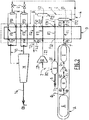
- the figure 1 shows an installation for implementing the basic steps of the process according to the invention, for treating a mixture 1 for the separation of carbon dioxide (CO 2 ) and hydrogen (H 2 ) from this mixture.
- cryogenic unit not all the illustrated elements operate at cryogenic temperatures. Only the low temperature part of the heat exchanger and the two phase separators, as well as the pipes joining them operate at temperatures below -10 ° C.
- PSA H 2 designate a adsorption module with pressure variation for hydrogen.
- cryogenic unit C comprises two independent exchangers D1 and D2, as is schematically represented by parallel dotted lines in FIG. figure 1 two options are conceivable: the first exchanger D1 comprises the circuit F1 and possibly the circuit F3, and the second exchanger D2 comprises the circuit F2 and possibly the circuit F3 (if the latter is not part of the first exchanger D1).
- the mixture 1 circulates in the cooling circuit F1 and is therefore cooled, for example at a very low temperature (about -50 ° C.), to condense the CO 2 present in the mixture 1.
- a very low temperature about -50 ° C.
- the condensation of CO 2 is obtained by applying to the mixture 1 conditions close to the triple point of CO 2 (5.2 bars at -56.6 ° C) so that the CO 2 passes in liquid form and can be separated from the remaining gases containing incondensables, such as CH 4 , CO, N 2 , Ar, H 2 .
- the first liquid 4 from the first phase separator E1 is thus rich in CO 2 (of the order of 95% to 99%), whereas the gas 3 leaving this separator E1 contains almost all the H 2 , a very large quantity of the most volatile molecules (CH 4 , CO, N 2 , Ar), and still a not insignificant amount of CO 2 .
- the gas 3 flows in the heating circuit F3 so that it exchanges heat with the fluids circulating in the other circuits F1, F2. Since the gas 3 is very cold, it will absorb heat and release cold circulating in the circuit F3, and leave this circuit with a temperature above its inlet temperature, which is why this circuit D3 is called heating circuit.
- the PSA H 2 B makes it possible to separate the hydrogen from the remainder of the constituents of the gas 3 leaving the circuit F3, with a yield of between 75% and 95%.
- the purity of the hydrogen produced (gas 5) is then greater than 99 mol%.
- 2 depleted gas H 2 generated by the H 2 PSA B contains meanwhile almost all the CO 2 present in the gas entering the H 2 PSA B, the other constituents (CH 4, CO, N 2, Ar ) and in particular a significant amount of H 2 resulting from the non-total yield of PSA H 2 B.
- the gas 2 circulates in the cooling circuit F1 and is therefore cooled, for example to a very low temperature (about -50 ° C.), to condense the CO 2 present in this gas 2, in the same conditions as those set out above (close to the triple point of CO 2 ).
- the second liquid 7 coming from the second phase separator E2 is thus rich in CO 2
- the gas 8 coming out of this separator E2 contains almost all of the incondensables (CH 4 , CO, N 2 , Ar) and a non-condensable quantity. negligible H 2 and CO 2 .
- the liquids 4 and 7 from phase separators E1 and E2 are rich in CO 2 .
- Such a method makes it possible to achieve an overall CO 2 recovery efficiency of more than 90%.
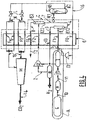
- the figure 2 shows an alternative embodiment of the installation for carrying out the process according to the invention, in which the mixture 1 to be treated is a synthesis gas.
- the reforming unit G makes it possible to generate, by an ATR, SMR or POX process, a mixture rich in CO and H 2 .
- the outlet G2 of the reforming unit G is connected to the inlet H1 of the shift reactor H which converts the mixture 10 into a gaseous mixture 11 enriched with CO 2 and H 2 .
- the outlet H 2 of the shift reactor H is connected to the inlet I 1 of the drying unit I, possibly via the compressor J 1, to produce a synthesis gas corresponding to the mixture 1.
- the technology used for the shift reaction (H) can be a high temperature shift ( High Temperature Shift ) or a high and low temperature shift ( High Temperature Shift + Low Temperature Shift ) or an isothermal shift ( Isothermal Shift in English) or an isothermal shift then low temperature ( Isothermal Shift + Low Temperature Shift ).
- Isothermal shift technology may be preferred because it allows a higher conversion rate.
- the reforming gas passes through catalyst-filled tubes immersed in water. The heat of the reformed gas is reused to produce the steam necessary for the reaction.
- the drying unit I makes it possible to dehydrate the gaseous mixture 11, for example by desiccation.
- this is the only drying step.
- the fact of placing this step at high pressure before the above-mentioned step i) makes it possible to maximize the drying efficiency and to increase the efficiency of the PSA H 2 B in step ii).
- a step of compressing the gas mixture 11 may possibly be added before the drying step in the unit I.
- This possible compression with respect to the drying step may result from an optimum between the fact of adsorbing the moisture at a high pressure and the cost of the adsorption bottles at such a pressure.
- the mixture 1 thus obtained consists mainly of H 2 , CO and CO 2 .
- the cryogenic unit C comprises a single multi-fluid heat exchanger, said main exchanger D.
- This comprises the first and second cooling circuits F1 and F2 and the heating circuit F3 described above.
- It also comprises a second heating circuit F4 whose input F41 is connected to the remaining gas outlet 8 of the second phase separator E2 and the output F42 provides a gas 12 containing substantially all the incondensables (CH 4 , CO, N 2 , Ar) and possibly a significant amount of H 2 and CO 2 .
- the passage of the gas 8 in the circuit F4 of the exchanger allows the gas 8 to absorb heat and release cold, which is recovered for condensation in steps i) and iii).
- the installation also comprises a compressor J2 whose input J21 is connected to the output B2 of the PSA H 2 B and the output J22 is connected to the input F21 of the second cooling circuit F2.
- This compressor J2 makes it possible to compress the depleted gas 2 into hydrogen produced by the PSA H 2 B, which is at low pressure (of the order of 1.0 to 5.0 bar), up to a high pressure (for example of the same order of magnitude as that of the mixture 1 entering the main exchanger D).
- the installation furthermore comprises a third heating circuit F5, pressure regulators K, valves L and a compressor M.
- the heating circuit F5 comprises several inputs F51 (here four inputs F51 are represented) connected to the outputs E12 and E22 of the two phase separators E1 and E2, via valves L and expander K, and several outputs F52 ( here, four outlets F52 are shown) connected to the compressor M.
- the liquids 4 and 7 leaving the two phase separators E1 and E2 are mixed and then expanded at different pressure levels and reheated in the circuits F5, releasing cold by vaporization, then out of these circuits to produce a stream 13 of purified CO 2 .
- the liquids 4, 7 may be subcooled through the main heat exchanger D (step not shown in the figure) in order to limit the flash during detents called "BP" and "HP” and thus limit the loss of cold caused by these flashes.
- the compressor M may be associated with a pump for delivering a stream 14 of purified CO 2 at a predetermined pressure.
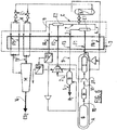
- the figure 3 shows another variant embodiment of the installation for implementing the method according to the invention, which differs from the previous variant of FIG. figure 2 essentially by the fact that the first cooling circuit F1 and the first phase separator E1 are replaced by two cooling circuits F1a, F1b and two phase separators E1a, E1b.
- This installation makes it possible to cool the mixture 1 in two stages and thus to reduce the cooling consumption of the installation.
- the second cooling circuit F2 and the heating circuits F3, F5 are identical to those of the variant of the installation described above with reference to FIG. figure 2 .
- the first cooling circuit F1a comprises an input F1a1 configured to be connected to the source A of said mixture 1 and an output F1a2 connected to the input E1a1 of a phase separator E1a.
- the intermediate cooling circuit F1b comprises a F1b1 input connected to the gas outlet E1a2 3a of this phase separator E1a and an F1b2 output connected to the input E1b1 of another phase separator E1b. As described above, the gas 3b leaving the phase separator E1b feeds the heating circuit F3.
- the liquids 4a and 4b from the phase separators E1a and E1b are rich in CO 2 and are here mixed with the liquid 7 from the phase separator E2, before being expanded and vaporized, as explained in the foregoing.
- the figure 4 shows another variant embodiment of the installation for implementing the method according to the invention.
- This variant differs from that described with reference to the figure 2 essentially in that the plant comprises a distillation column N.
- This distillation column N comprises an inlet N1 connected, for example via a valve, to the outlets E12 and E22 of liquids 4, 7 of the two separators of phases E1 and E2.
- the distillation column N further comprises a first outlet N 2 providing a fraction 15 rich in CO 2 with a high purity, and a second outlet N 3 providing a fraction 16 depleted in CO 2 .
- the first outlet N2 of the column N is connected to the heating circuit F5 via the valves L and the pressure regulators K.
- the fraction 15 is thus transformed into stream 13 of purified CO 2 and then stream 14 of purified CO 2 at pressure predetermined, as previously described.
- the CO 2 still present in the fraction 16 can be at least partly recovered within the cryogenic unit C, which makes it possible to maintain a high CO 2 recovery yield.
- the figure 5 shows another variant embodiment of the installation for implementing the method according to the invention.
- This variant differs from that of the figure 2 essentially in that the installation further comprises two membrane systems O1 and O2.
- the first system O1 membrane (s) allows to recover the hydrogen remaining in the gas 8 out of the second phase separator E2, while the second system O2 can recover the CO 2 .
- the first system O1 comprises an input O11 connected to the output F42 of the heating circuit F4, a first output O12 providing a permeate 17 rich in H 2 and a second output O 13 providing a residue 18 rich in CO 2 .
- the first output O12 of the system O1 can be connected to an input B1 or B3 of the PSA H 2 B and / or to the input I1 of the drying unit I, either directly or via a compressor which may be a dedicated compressor J4 connected to the PSA or the aforementioned compressor J1 connected to the drying unit I. It may indeed be necessary to compress the permeate 17 which is recovered at a pressure much lower than that of the remaining gas 8 entering the first system O1 because of the pressure difference on which the principle of permeation and separation in a membrane is based.
- the permeate 17 it may possibly be compressed before being recycled. In the case where its pressure is lower than the operating pressure of the PSA H 2 B, it can be compressed in the dedicated compressor J4 before recycling to the PSA H 2 B or compressed in the compressor J1 placed after the shift reactor H, before step i). If its pressure is equal to or greater than the operating pressure of the PSA H 2 B, the permeate can be recycled directly to the PSA H 2 B.
- Said residue 18 leaving the first system O1 is recovered at a still high pressure and contains a large majority of the CO 2 present at the inlet of the first module O1, the H 2 as well as all the other constituents (CH 4 , CO, N 2 , Ar) not evacuated in the permeate 17. It is therefore treated in the second system O2 membrane (s) whose entry O21 is connected to the second output O13 of the first module O1.
- This second system O2 comprises a first output O22 providing a permeate 19 rich in CO 2 and a second output O23 providing a residue 20 rich in CH 4 , CO, N 2 and Ar and poor in H 2 and CO 2 .
- the first output O22 may be connected to the input F21 of the cooling circuit F2 directly or via a compressor, in particular the compressor J2, depending on the pressure of the permeate 19.
- this permeate 19 rich in CO 2 can be recycled by mixing it with the gas 2 depleted in H 2 , between steps ii) and iii), upstream of the phase separator E 2.
- Such a variant makes it possible to recover the CO 2 and H 2 contained in a significant amount (from 40% to 60% of H 2 and from 15% to 35% of CO 2 ) in the remaining gas 8 coming from the second separator of E2 phases and thus achieve very high recovery yields of CO 2 , more than 95%, and H 2 recovery yields of the order of 75% to more than 98%, for example.
- the figure 6 shows another variant embodiment of the installation for implementing the method according to the invention.
- This variant corresponds substantially to the combination of the variants of the figures 4 and 5 , the installation comprising here a distillation column N and two membrane systems O1 and O2.
- This variant makes it possible to obtain a liquid rich in CO 2 with a high purity and a high recovery efficiency of CO 2 and H 2 .
Landscapes
- Engineering & Computer Science (AREA)
- Chemical & Material Sciences (AREA)
- Mechanical Engineering (AREA)
- Thermal Sciences (AREA)
- General Engineering & Computer Science (AREA)
- Physics & Mathematics (AREA)
- Organic Chemistry (AREA)
- Combustion & Propulsion (AREA)
- Inorganic Chemistry (AREA)
- Chemical Kinetics & Catalysis (AREA)
- Hydrogen, Water And Hydrids (AREA)
- Carbon And Carbon Compounds (AREA)
- Separation By Low-Temperature Treatments (AREA)
Claims (15)
- Verfahren zur Behandlung eines Gemischs (1) zur Abscheidung von Kohlendioxid und Wasserstoff aus diesem Gemisch, wobei:i) das Gemisch (1) gekühlt und teilweise kondensiert wird und eine erste Flüssigkeit (4) in einem ersten Phasenabscheider (E1) von dem Gemisch abgeschieden wird,ii) ein Gas (3) aus dem ersten Phasenabscheider (E1) in einem Adsorptionsmodul mit Druckänderung für Wasserstoff (B) zum Erzeugen eines wasserstoffreichen Gases (5) und eines wasserstoffabgereicherten Restgases (2) behandelt wird, undiii) das wasserstoffabgereicherte Restgas (2) gekühlt und teilweise kondensiert wird und eine zweite Flüssigkeit (7) von dem verbleibenden Gas (8) in einem zweiten Phasenabscheider (E2), getrennt vom ersten Phasenabscheider (E1), abgeschieden wird,wobei die erste und zweite Flüssigkeit (4, 7) reich an Kohlendioxid sind, dadurch gekennzeichnet, dass die Teilkondensationen in den Schritten i) und iii) in derselben kryogenen Einheit (C) durchgeführt werden.
- Verfahren nach Anspruch 1, wobei die Teilkondensationen in den Schritten i) und iii) in demselben Wärmeaustauscher (D) durchgeführt werden.
- Verfahren nach einem der vorstehenden Ansprüche, wobei das Gemisch (1) in Schritt i) bei einer Temperatur von unter -20 °C, und insbesondere unter -40 °C, teilweise kondensiert wird.
- Verfahren nach einem der vorstehenden Ansprüche, wobei der Schritt i) die folgenden Teilschritte umfasst:- eine erste Teilkondensation des Gemischs (1) bei einer Temperatur von unter -20 °C und insbesondere in der Nähe von etwa -40 °C,- eine Abscheidung der Flüssigkeit (4a) vom Rest des Gemischs (3a) in einem Phasenabscheider (E1a),- eine zweite Teilkondensation des Rests des Gemischs (3a) bei einer Temperatur von unter -40 °C, und insbesondere bei etwa -50 °C,- eine Abscheidung der Flüssigkeit (4b) vom verbleibenden Gas (3b) in einem anderen Phasenabscheider (E1b), wobei die Flüssigkeit (4a, 4b) reich an Kohlendioxid ist.
- Verfahren nach einem der vorstehenden Ansprüche, umfassend, vor dem Schritt i), einen Vorschritt zum Erzeugen eines CO- und H2-reichen Gemischs (10), zum Beispiel durch ein autothermisches Reformierungsverfahren (ATR), ein Kohlenwasserstoffdampfreformierungsverfahren (SMR) oder ein Teiloxidationsverfahren (POX).
- Verfahren nach Anspruch 5, wobei das CO- und H2-reiche Gemisch (10) in einem Verschiebungsreaktor (H) behandelt wird, um ein mit CO2 und H2 angereichertes Gemisch (11) zu erhalten.
- Verfahren nach Anspruch 5 oder 6, wobei das Gemisch (11) komprimiert und/oder dehydriert wird.
- Verfahren nach einem der vorstehenden Ansprüche, wobei das Gas (2) im Schritt iii) bei einer Temperatur von unter -20 °C, und insbesondere unter -40 °C, teilweise kondensiert wird.
- Verfahren nach einem der vorstehenden Ansprüche, wobei die Flüssigkeit (4, 7) destilliert wird, um eine CO2-reiche Fraktion (15) und eine CO2-abgereicherte Fraktion (16) bereitzustellen.
- Verfahren nach Anspruch 9, wobei die CO2-abgereicherte Fraktion (16) durch Mischen derselben mit dem Gemisch (1) vor dem Schritt i) stromaufwärts des ersten Phasenabscheiders (E1) oder durch Mischen derselben mit dem wasserstoffabgereicherten Gas (2) zwischen den Schritten ii) und iii) stromaufwärts des zweiten Phasenabscheiders (E2) rezykliert wird.
- Verfahren nach einem der vorstehenden Ansprüche, wobei das verbleibende Gas (8), das aus dem zweiten Phasenabscheider (E2) hervorgeht, durch mindestens ein Membransystem (O1, O2) gefiltert wird.
- Einrichtung zur Durchführung des Verfahrens nach einem der vorstehenden Ansprüche, umfassend:- ein Adsorptionsmodul mit Druckänderung für Wasserstoff (B) und- eine kryogene Einheit (C), die einen ersten und einen zweiten Phasenabscheider (E1 E2), und einen Wärmeaustauscher (D) aufweist, der einen ersten Kühlkreislauf (F1) aufweist, von dem ein Einlass (F11) konfiguriert ist, um mit einer Quelle (M) des Gemischs (1) verbunden zu werden, und von dem ein Auslass (F12) mit dem ersten Phasenabscheider (E1) verbunden ist, von dem ein Auslass (E12) für Gas (3) mit einem Einlass (B1) des Adsorptionsmoduls mit Druckänderung für Wasserstoff (B) verbunden ist, wobei das Adsorptionsmodul mit Druckänderung für Wasserstoff einen Auslass (B2) für wasserstoffarmes Gas (2) aufweist, der mit einem Einlass (F21) eines zweiten Kühlkreislaufs (F2) des Wärmeaustauschers (D) oder eines anderen Wärmeaustauschers der kryogenen Einheit (C) verbunden ist, wobei ein Auslass (F22) dieses zweiten Kühlkreislaufs (F2) mit dem zweiten Phasenabscheider (E2) verbunden ist.
- Installation nach Anspruch 12, wobei der Wärmeaustauscher (D). der den ersten und/oder den zweiten Kühlkreislauf (F1, F2) aufweist, einen Heizkreislauf (F3) umfasst, von dem ein Einlass (F31) mit dem Auslass (E12) für Gas (3) des ersten Phasenabscheiders (E1) verbunden ist und von dem der Auslass (F31) mit dem Einlass (B1) des Adsorptionsmoduls mit Druckänderung für Wasserstoff (B) verbunden ist.
- Installation nach Anspruch 12 oder 13, die ferner mindestens ein Element aus den Folgenden aufweist:- eine Reformierungseinheit (G),- einen Verschiebungsreaktor (H),- eine Trocknungseinheit (I),- eine Destillationskolonne (N),- mindestens ein Membransystem (O1, O2),- mindestens einen Kompressor (M, J1, J2, J3, J4),- mindestens ein Expansionsventil (K),- mindestens ein Ventil (L),- mindestens eine Pumpe.
- Installation nach einem der Ansprüche 12 bis 14, die einen mit dem Adsorptionsmodul mit Druckänderung für Wasserstoff (B) verbundenen Wasserstoffgasauslass (5) aufweist.
Applications Claiming Priority (2)
| Application Number | Priority Date | Filing Date | Title |
|---|---|---|---|
| FR1454349A FR3021044B1 (fr) | 2014-05-15 | 2014-05-15 | Procede de traitement pour la separation de dioxyde de carbone et d’hydrogene d’un melange |
| PCT/FR2015/051224 WO2015173499A1 (fr) | 2014-05-15 | 2015-05-11 | Procédé de traitement pour la séparation de dioxyde de carbone et d'hydrogène d'un mélange |
Publications (2)
| Publication Number | Publication Date |
|---|---|
| EP3142967A1 EP3142967A1 (de) | 2017-03-22 |
| EP3142967B1 true EP3142967B1 (de) | 2019-02-20 |
Family
ID=51352600
Family Applications (1)
| Application Number | Title | Priority Date | Filing Date |
|---|---|---|---|
| EP15725839.3A Active EP3142967B1 (de) | 2014-05-15 | 2015-05-11 | Behandlungsverfahren zur abscheidung von kohlendioxid und wasserstoff aus einer mischung |
Country Status (6)
| Country | Link |
|---|---|
| US (1) | US10392251B2 (de) |
| EP (1) | EP3142967B1 (de) |
| CN (1) | CN106458581A (de) |
| CA (1) | CA2948758A1 (de) |
| FR (1) | FR3021044B1 (de) |
| WO (1) | WO2015173499A1 (de) |
Families Citing this family (8)
| Publication number | Priority date | Publication date | Assignee | Title |
|---|---|---|---|---|
| FR3090832B1 (fr) * | 2018-12-19 | 2022-08-12 | L´Air Liquide Sa Pour L’Etude Et L’Exploitation Des Procedes Georges Claude | Procédé et appareil de séparation d’un courant d’alimentation comprenant au moins du CO2 ainsi qu’au moins un composé léger |
| CN110921616B (zh) * | 2019-10-28 | 2023-08-01 | 中科液态阳光(苏州)氢能科技发展有限公司 | 二氧化碳混合余气重整方法 |
| FR3105014B1 (fr) * | 2019-12-19 | 2022-07-22 | Air Liquide | Procédé et appareil de séparation de dioxyde de carbone d’un gaz résiduaire d'une installation de craquage catalytique sur lit fluidisé (FCC) |
| CN110980645A (zh) * | 2019-12-27 | 2020-04-10 | 乔治洛德方法研究和开发液化空气有限公司 | 一种蒸汽烃类重整方法 |
| FR3122725B1 (fr) | 2021-05-04 | 2023-11-24 | Air Liquide | Procédé et appareil de séparation d’un mélange d’hydrogène et de monoxyde de carbone à basse température |
| JP2023027674A (ja) * | 2021-08-17 | 2023-03-02 | 国立研究開発法人産業技術総合研究所 | 高圧水素供給システム及びその方法 |
| CN115585628B (zh) * | 2022-09-30 | 2025-12-09 | 烟台龙源电力技术股份有限公司 | 一种烟气中二氧化碳处理系统及烟气中二氧化碳纯化方法 |
| EP4520416A1 (de) * | 2023-09-11 | 2025-03-12 | L'air Liquide, Societe Anonyme Pour L'etude Et L'exploitation Des Procedes Georges Claude | Verfahren und vorrichtung zur abscheidung von co2 aus einem co2-haltigen einsatzstrom, mindestens einer leichteren und mindestens einer schwereren komponente |
Family Cites Families (12)
| Publication number | Priority date | Publication date | Assignee | Title |
|---|---|---|---|---|
| US4963339A (en) * | 1988-05-04 | 1990-10-16 | The Boc Group, Inc. | Hydrogen and carbon dioxide coproduction |
| US6500241B2 (en) * | 2000-12-19 | 2002-12-31 | Fluor Corporation | Hydrogen and carbon dioxide coproduction |
| FR2877939B1 (fr) * | 2004-11-16 | 2007-02-02 | Air Liquide | Procede et installation pour la production combinee d'hydrogene et de dioxyde de carbone |
| EP1858803B1 (de) * | 2005-03-14 | 2016-07-06 | Geoffrey Gerald Weedon | Verfahren zur herstellung von wasserstoff unter gleichzeitiger herstellung und abfangung von kohlendioxid |
| US7618478B2 (en) * | 2006-04-03 | 2009-11-17 | Praxair Technology, Inc. | Process and apparatus to recover medium purity carbon dioxide |
| FR2911390B1 (fr) * | 2007-01-16 | 2009-04-17 | Air Liquide | Procede et appareil de production de monoxyde de carbone par distillation cryogenique |
| EP2366447B1 (de) * | 2007-03-29 | 2014-12-17 | Nippon Oil Corporation | Verfahren und Vorrichtung zur Herstellung von Wasserstoff und Wiedergewinnung von Kohlendioxid |
| EP2023066A1 (de) | 2007-07-25 | 2009-02-11 | BP Alternative Energy Holdings Limited | Trennung von Kohlendioxid und Wasserstoff |
| CA2693994A1 (en) * | 2007-07-25 | 2009-01-29 | Bp Alternative Energy International Limited | Separation of carbon dioxide and hydrogen |
| EP2149769A1 (de) * | 2008-07-31 | 2010-02-03 | BP Alternative Energy International Limited | Trennung von Kohlendioxid und Wasserstoff |
| FR2939785B1 (fr) * | 2008-12-11 | 2012-01-27 | Air Liquide | Production d'hydrogene a partir de gaz reforme et capture simultanee du co2 coproduit. |
| AU2010222763A1 (en) * | 2009-03-09 | 2011-09-22 | Bp Alternative Energy International Limited | Separation of carbon dioxide and hydrogen |
-
2014
- 2014-05-15 FR FR1454349A patent/FR3021044B1/fr not_active Expired - Fee Related
-
2015
- 2015-05-11 US US15/311,390 patent/US10392251B2/en active Active
- 2015-05-11 EP EP15725839.3A patent/EP3142967B1/de active Active
- 2015-05-11 WO PCT/FR2015/051224 patent/WO2015173499A1/fr not_active Ceased
- 2015-05-11 CA CA2948758A patent/CA2948758A1/en not_active Abandoned
- 2015-05-11 CN CN201580035117.6A patent/CN106458581A/zh active Pending
Non-Patent Citations (1)
| Title |
|---|
| None * |
Also Published As
| Publication number | Publication date |
|---|---|
| FR3021044B1 (fr) | 2018-01-26 |
| EP3142967A1 (de) | 2017-03-22 |
| CN106458581A (zh) | 2017-02-22 |
| CA2948758A1 (en) | 2015-11-19 |
| FR3021044A1 (fr) | 2015-11-20 |
| US10392251B2 (en) | 2019-08-27 |
| US20170081186A1 (en) | 2017-03-23 |
| WO2015173499A1 (fr) | 2015-11-19 |
Similar Documents
| Publication | Publication Date | Title |
|---|---|---|
| EP3142967B1 (de) | Behandlungsverfahren zur abscheidung von kohlendioxid und wasserstoff aus einer mischung | |
| EP3713870B1 (de) | Verfahren und vorrichtung zur kombinierten herstellung von wasserstoff und kohlendioxid aus einem kohlenwasserstoffgemisch | |
| CA2587416C (fr) | Procede et installation pour la production combinee d'hydrogene et de dioxyde de carbone | |
| EP3465035B1 (de) | Verfahren zur kryogenen trennung eines methan- und luftgashaltigen einsatzstroms, anlage zur herstellung von biomethan durch reinigung von biogasen aus nicht-gefährlichen abfallbehältern (nhwsf) zur durchführung des verfahrens | |
| EP0032096A2 (de) | Verfahren zur Herstellung von Ammoniak und des übereinstimmenden Synthesegases | |
| EP3867584A1 (de) | Anlage und verfahren zur herstellung von verflüssigtem methan | |
| FR3075659A1 (fr) | Procede de production d'un courant de gaz naturel a partir d'un courant de biogaz. | |
| CA2742206A1 (fr) | Production d'hydrogene a partir de gaz reforme et capture simultanee du co2 co-produit | |
| FR2992307A1 (fr) | Procede et installation pour la production combinee de gaz de synthese d'ammoniac et de dioxyde de carbone | |
| EP4410401B1 (de) | Verfahren und vorrichtung zur trennung eines gemisches aus wasserstoff und kohlendioxid | |
| EP2409950B1 (de) | Verfahren zur Erzeugung von Wasserstoff mit Zwischendruckspülung | |
| EP3727648B1 (de) | Verfahren zum destillieren eines sauerstoffhaltigen gasstroms | |
| WO2025149549A1 (fr) | Procédé et appareil de capture de co2 par condensation partielle et/ou distillation et/ou lavage et/ou solidification | |
| WO2011148066A2 (fr) | Procédé de production anaérobie d'hydrogène | |
| FR2847568A1 (fr) | Procede et installation de production d'un melange krypton/xenon a partir d'air | |
| WO2018087499A1 (fr) | Mise en œuvre de la vapeur d'un procédé de production de gaz de synthèse pour réchauffer des vapeurs de gaz naturel | |
| FR3120232A3 (fr) | Procédé d’ultra-purification d’une fraction de l’hydrogène issu d’un PSA H2 | |
| WO2018087500A1 (fr) | Intégration d'un procédé de liquéfaction de gaz naturel dans un procédé de production de gaz de synthèse | |
| WO2018087497A1 (fr) | Procédé de liquéfaction de gaz naturel combiné à une production de gaz de synthèse | |
| WO2022106768A1 (fr) | Procede de separation cryogenique d'un debit d'alimentation a base de biomethane, procede de production de biomethane integrant ladite separation cryogenique et installation associee | |
| FR3144928A1 (fr) | Procédé et appareil de séparation membranaire d’un mélange contenant majoritairement de l’hydrogène et du dioxyde de carbone | |
| FR3075658A1 (fr) | Procede de limitation de la concentration d'oxygene contenu dans un courant de biomethane |
Legal Events
| Date | Code | Title | Description |
|---|---|---|---|
| STAA | Information on the status of an ep patent application or granted ep patent |
Free format text: STATUS: THE INTERNATIONAL PUBLICATION HAS BEEN MADE |
|
| PUAI | Public reference made under article 153(3) epc to a published international application that has entered the european phase |
Free format text: ORIGINAL CODE: 0009012 |
|
| STAA | Information on the status of an ep patent application or granted ep patent |
Free format text: STATUS: REQUEST FOR EXAMINATION WAS MADE |
|
| 17P | Request for examination filed |
Effective date: 20161215 |
|
| AK | Designated contracting states |
Kind code of ref document: A1 Designated state(s): AL AT BE BG CH CY CZ DE DK EE ES FI FR GB GR HR HU IE IS IT LI LT LU LV MC MK MT NL NO PL PT RO RS SE SI SK SM TR |
|
| AX | Request for extension of the european patent |
Extension state: BA ME |
|
| DAV | Request for validation of the european patent (deleted) | ||
| DAX | Request for extension of the european patent (deleted) | ||
| RIC1 | Information provided on ipc code assigned before grant |
Ipc: F25J 3/02 20060101ALI20180810BHEP Ipc: C01B 3/50 20060101AFI20180810BHEP Ipc: C01B 3/56 20060101ALI20180810BHEP Ipc: F25J 3/06 20060101ALI20180810BHEP |
|
| GRAP | Despatch of communication of intention to grant a patent |
Free format text: ORIGINAL CODE: EPIDOSNIGR1 |
|
| STAA | Information on the status of an ep patent application or granted ep patent |
Free format text: STATUS: GRANT OF PATENT IS INTENDED |
|
| INTG | Intention to grant announced |
Effective date: 20180924 |
|
| GRAJ | Information related to disapproval of communication of intention to grant by the applicant or resumption of examination proceedings by the epo deleted |
Free format text: ORIGINAL CODE: EPIDOSDIGR1 |
|
| STAA | Information on the status of an ep patent application or granted ep patent |
Free format text: STATUS: REQUEST FOR EXAMINATION WAS MADE |
|
| GRAP | Despatch of communication of intention to grant a patent |
Free format text: ORIGINAL CODE: EPIDOSNIGR1 |
|
| STAA | Information on the status of an ep patent application or granted ep patent |
Free format text: STATUS: GRANT OF PATENT IS INTENDED |
|
| INTC | Intention to grant announced (deleted) | ||
| GRAS | Grant fee paid |
Free format text: ORIGINAL CODE: EPIDOSNIGR3 |
|
| INTG | Intention to grant announced |
Effective date: 20181221 |
|
| GRAA | (expected) grant |
Free format text: ORIGINAL CODE: 0009210 |
|
| STAA | Information on the status of an ep patent application or granted ep patent |
Free format text: STATUS: THE PATENT HAS BEEN GRANTED |
|
| AK | Designated contracting states |
Kind code of ref document: B1 Designated state(s): AL AT BE BG CH CY CZ DE DK EE ES FI FR GB GR HR HU IE IS IT LI LT LU LV MC MK MT NL NO PL PT RO RS SE SI SK SM TR |
|
| REG | Reference to a national code |
Ref country code: GB Ref legal event code: FG4D Free format text: NOT ENGLISH |
|
| REG | Reference to a national code |
Ref country code: CH Ref legal event code: EP |
|
| REG | Reference to a national code |
Ref country code: DE Ref legal event code: R096 Ref document number: 602015024856 Country of ref document: DE |
|
| REG | Reference to a national code |
Ref country code: AT Ref legal event code: REF Ref document number: 1097904 Country of ref document: AT Kind code of ref document: T Effective date: 20190315 |
|
| REG | Reference to a national code |
Ref country code: IE Ref legal event code: FG4D Free format text: LANGUAGE OF EP DOCUMENT: FRENCH |
|
| REG | Reference to a national code |
Ref country code: NL Ref legal event code: FP |
|
| REG | Reference to a national code |
Ref country code: LT Ref legal event code: MG4D |
|
| PG25 | Lapsed in a contracting state [announced via postgrant information from national office to epo] |
Ref country code: PT Free format text: LAPSE BECAUSE OF FAILURE TO SUBMIT A TRANSLATION OF THE DESCRIPTION OR TO PAY THE FEE WITHIN THE PRESCRIBED TIME-LIMIT Effective date: 20190620 Ref country code: SE Free format text: LAPSE BECAUSE OF FAILURE TO SUBMIT A TRANSLATION OF THE DESCRIPTION OR TO PAY THE FEE WITHIN THE PRESCRIBED TIME-LIMIT Effective date: 20190220 Ref country code: FI Free format text: LAPSE BECAUSE OF FAILURE TO SUBMIT A TRANSLATION OF THE DESCRIPTION OR TO PAY THE FEE WITHIN THE PRESCRIBED TIME-LIMIT Effective date: 20190220 Ref country code: NO Free format text: LAPSE BECAUSE OF FAILURE TO SUBMIT A TRANSLATION OF THE DESCRIPTION OR TO PAY THE FEE WITHIN THE PRESCRIBED TIME-LIMIT Effective date: 20190520 Ref country code: LT Free format text: LAPSE BECAUSE OF FAILURE TO SUBMIT A TRANSLATION OF THE DESCRIPTION OR TO PAY THE FEE WITHIN THE PRESCRIBED TIME-LIMIT Effective date: 20190220 |
|
| PG25 | Lapsed in a contracting state [announced via postgrant information from national office to epo] |
Ref country code: GR Free format text: LAPSE BECAUSE OF FAILURE TO SUBMIT A TRANSLATION OF THE DESCRIPTION OR TO PAY THE FEE WITHIN THE PRESCRIBED TIME-LIMIT Effective date: 20190521 Ref country code: IS Free format text: LAPSE BECAUSE OF FAILURE TO SUBMIT A TRANSLATION OF THE DESCRIPTION OR TO PAY THE FEE WITHIN THE PRESCRIBED TIME-LIMIT Effective date: 20190620 Ref country code: HR Free format text: LAPSE BECAUSE OF FAILURE TO SUBMIT A TRANSLATION OF THE DESCRIPTION OR TO PAY THE FEE WITHIN THE PRESCRIBED TIME-LIMIT Effective date: 20190220 Ref country code: LV Free format text: LAPSE BECAUSE OF FAILURE TO SUBMIT A TRANSLATION OF THE DESCRIPTION OR TO PAY THE FEE WITHIN THE PRESCRIBED TIME-LIMIT Effective date: 20190220 Ref country code: RS Free format text: LAPSE BECAUSE OF FAILURE TO SUBMIT A TRANSLATION OF THE DESCRIPTION OR TO PAY THE FEE WITHIN THE PRESCRIBED TIME-LIMIT Effective date: 20190220 Ref country code: BG Free format text: LAPSE BECAUSE OF FAILURE TO SUBMIT A TRANSLATION OF THE DESCRIPTION OR TO PAY THE FEE WITHIN THE PRESCRIBED TIME-LIMIT Effective date: 20190520 |
|
| REG | Reference to a national code |
Ref country code: AT Ref legal event code: MK05 Ref document number: 1097904 Country of ref document: AT Kind code of ref document: T Effective date: 20190220 |
|
| PG25 | Lapsed in a contracting state [announced via postgrant information from national office to epo] |
Ref country code: RO Free format text: LAPSE BECAUSE OF FAILURE TO SUBMIT A TRANSLATION OF THE DESCRIPTION OR TO PAY THE FEE WITHIN THE PRESCRIBED TIME-LIMIT Effective date: 20190220 Ref country code: IT Free format text: LAPSE BECAUSE OF FAILURE TO SUBMIT A TRANSLATION OF THE DESCRIPTION OR TO PAY THE FEE WITHIN THE PRESCRIBED TIME-LIMIT Effective date: 20190220 Ref country code: EE Free format text: LAPSE BECAUSE OF FAILURE TO SUBMIT A TRANSLATION OF THE DESCRIPTION OR TO PAY THE FEE WITHIN THE PRESCRIBED TIME-LIMIT Effective date: 20190220 Ref country code: CZ Free format text: LAPSE BECAUSE OF FAILURE TO SUBMIT A TRANSLATION OF THE DESCRIPTION OR TO PAY THE FEE WITHIN THE PRESCRIBED TIME-LIMIT Effective date: 20190220 Ref country code: ES Free format text: LAPSE BECAUSE OF FAILURE TO SUBMIT A TRANSLATION OF THE DESCRIPTION OR TO PAY THE FEE WITHIN THE PRESCRIBED TIME-LIMIT Effective date: 20190220 Ref country code: DK Free format text: LAPSE BECAUSE OF FAILURE TO SUBMIT A TRANSLATION OF THE DESCRIPTION OR TO PAY THE FEE WITHIN THE PRESCRIBED TIME-LIMIT Effective date: 20190220 Ref country code: AL Free format text: LAPSE BECAUSE OF FAILURE TO SUBMIT A TRANSLATION OF THE DESCRIPTION OR TO PAY THE FEE WITHIN THE PRESCRIBED TIME-LIMIT Effective date: 20190220 Ref country code: SK Free format text: LAPSE BECAUSE OF FAILURE TO SUBMIT A TRANSLATION OF THE DESCRIPTION OR TO PAY THE FEE WITHIN THE PRESCRIBED TIME-LIMIT Effective date: 20190220 |
|
| REG | Reference to a national code |
Ref country code: DE Ref legal event code: R097 Ref document number: 602015024856 Country of ref document: DE |
|
| PG25 | Lapsed in a contracting state [announced via postgrant information from national office to epo] |
Ref country code: PL Free format text: LAPSE BECAUSE OF FAILURE TO SUBMIT A TRANSLATION OF THE DESCRIPTION OR TO PAY THE FEE WITHIN THE PRESCRIBED TIME-LIMIT Effective date: 20190220 Ref country code: SM Free format text: LAPSE BECAUSE OF FAILURE TO SUBMIT A TRANSLATION OF THE DESCRIPTION OR TO PAY THE FEE WITHIN THE PRESCRIBED TIME-LIMIT Effective date: 20190220 |
|
| PLBE | No opposition filed within time limit |
Free format text: ORIGINAL CODE: 0009261 |
|
| STAA | Information on the status of an ep patent application or granted ep patent |
Free format text: STATUS: NO OPPOSITION FILED WITHIN TIME LIMIT |
|
| REG | Reference to a national code |
Ref country code: CH Ref legal event code: PL |
|
| PG25 | Lapsed in a contracting state [announced via postgrant information from national office to epo] |
Ref country code: AT Free format text: LAPSE BECAUSE OF FAILURE TO SUBMIT A TRANSLATION OF THE DESCRIPTION OR TO PAY THE FEE WITHIN THE PRESCRIBED TIME-LIMIT Effective date: 20190220 |
|
| 26N | No opposition filed |
Effective date: 20191121 |
|
| PG25 | Lapsed in a contracting state [announced via postgrant information from national office to epo] |
Ref country code: CH Free format text: LAPSE BECAUSE OF NON-PAYMENT OF DUE FEES Effective date: 20190531 Ref country code: LI Free format text: LAPSE BECAUSE OF NON-PAYMENT OF DUE FEES Effective date: 20190531 Ref country code: MC Free format text: LAPSE BECAUSE OF FAILURE TO SUBMIT A TRANSLATION OF THE DESCRIPTION OR TO PAY THE FEE WITHIN THE PRESCRIBED TIME-LIMIT Effective date: 20190220 |
|
| PG25 | Lapsed in a contracting state [announced via postgrant information from national office to epo] |
Ref country code: SI Free format text: LAPSE BECAUSE OF FAILURE TO SUBMIT A TRANSLATION OF THE DESCRIPTION OR TO PAY THE FEE WITHIN THE PRESCRIBED TIME-LIMIT Effective date: 20190220 Ref country code: LU Free format text: LAPSE BECAUSE OF NON-PAYMENT OF DUE FEES Effective date: 20190511 |
|
| PG25 | Lapsed in a contracting state [announced via postgrant information from national office to epo] |
Ref country code: TR Free format text: LAPSE BECAUSE OF FAILURE TO SUBMIT A TRANSLATION OF THE DESCRIPTION OR TO PAY THE FEE WITHIN THE PRESCRIBED TIME-LIMIT Effective date: 20190220 |
|
| PG25 | Lapsed in a contracting state [announced via postgrant information from national office to epo] |
Ref country code: IE Free format text: LAPSE BECAUSE OF NON-PAYMENT OF DUE FEES Effective date: 20190511 |
|
| PG25 | Lapsed in a contracting state [announced via postgrant information from national office to epo] |
Ref country code: CY Free format text: LAPSE BECAUSE OF FAILURE TO SUBMIT A TRANSLATION OF THE DESCRIPTION OR TO PAY THE FEE WITHIN THE PRESCRIBED TIME-LIMIT Effective date: 20190220 |
|
| PG25 | Lapsed in a contracting state [announced via postgrant information from national office to epo] |
Ref country code: MT Free format text: LAPSE BECAUSE OF FAILURE TO SUBMIT A TRANSLATION OF THE DESCRIPTION OR TO PAY THE FEE WITHIN THE PRESCRIBED TIME-LIMIT Effective date: 20190220 Ref country code: HU Free format text: LAPSE BECAUSE OF FAILURE TO SUBMIT A TRANSLATION OF THE DESCRIPTION OR TO PAY THE FEE WITHIN THE PRESCRIBED TIME-LIMIT; INVALID AB INITIO Effective date: 20150511 |
|
| PG25 | Lapsed in a contracting state [announced via postgrant information from national office to epo] |
Ref country code: MK Free format text: LAPSE BECAUSE OF FAILURE TO SUBMIT A TRANSLATION OF THE DESCRIPTION OR TO PAY THE FEE WITHIN THE PRESCRIBED TIME-LIMIT Effective date: 20190220 |
|
| P01 | Opt-out of the competence of the unified patent court (upc) registered |
Effective date: 20230523 |
|
| PGFP | Annual fee paid to national office [announced via postgrant information from national office to epo] |
Ref country code: NL Payment date: 20250521 Year of fee payment: 11 |
|
| PGFP | Annual fee paid to national office [announced via postgrant information from national office to epo] |
Ref country code: DE Payment date: 20250521 Year of fee payment: 11 |
|
| PGFP | Annual fee paid to national office [announced via postgrant information from national office to epo] |
Ref country code: GB Payment date: 20250521 Year of fee payment: 11 |
|
| PGFP | Annual fee paid to national office [announced via postgrant information from national office to epo] |
Ref country code: BE Payment date: 20250521 Year of fee payment: 11 |
|
| PGFP | Annual fee paid to national office [announced via postgrant information from national office to epo] |
Ref country code: FR Payment date: 20250528 Year of fee payment: 11 |