EP3143224B1 - Système de verrouillage - Google Patents
Système de verrouillage Download PDFInfo
- Publication number
- EP3143224B1 EP3143224B1 EP15729591.6A EP15729591A EP3143224B1 EP 3143224 B1 EP3143224 B1 EP 3143224B1 EP 15729591 A EP15729591 A EP 15729591A EP 3143224 B1 EP3143224 B1 EP 3143224B1
- Authority
- EP
- European Patent Office
- Prior art keywords
- lock
- output housing
- shaft
- lock input
- input
- Prior art date
- Legal status (The legal status is an assumption and is not a legal conclusion. Google has not performed a legal analysis and makes no representation as to the accuracy of the status listed.)
- Not-in-force
Links
- 239000004020 conductor Substances 0.000 claims description 25
- 230000007246 mechanism Effects 0.000 claims description 18
- 238000000034 method Methods 0.000 claims description 12
- 230000009471 action Effects 0.000 claims description 11
- 230000008569 process Effects 0.000 claims description 9
- 239000012774 insulation material Substances 0.000 claims description 4
- 238000009413 insulation Methods 0.000 claims description 3
- 238000002844 melting Methods 0.000 claims description 3
- 230000008018 melting Effects 0.000 claims description 3
- 230000005540 biological transmission Effects 0.000 claims description 2
- 230000008901 benefit Effects 0.000 description 2
- 238000010292 electrical insulation Methods 0.000 description 2
- 230000005611 electricity Effects 0.000 description 2
- 229920004943 Delrin® Polymers 0.000 description 1
- 230000002950 deficient Effects 0.000 description 1
- 230000007704 transition Effects 0.000 description 1
Images


Classifications
-
- E—FIXED CONSTRUCTIONS
- E05—LOCKS; KEYS; WINDOW OR DOOR FITTINGS; SAFES
- E05B—LOCKS; ACCESSORIES THEREFOR; HANDCUFFS
- E05B47/00—Operating or controlling locks or other fastening devices by electric or magnetic means
- E05B47/0001—Operating or controlling locks or other fastening devices by electric or magnetic means with electric actuators; Constructional features thereof
- E05B47/0009—Operating or controlling locks or other fastening devices by electric or magnetic means with electric actuators; Constructional features thereof with thermo-electric actuators, e.g. heated bimetals
-
- E—FIXED CONSTRUCTIONS
- E05—LOCKS; KEYS; WINDOW OR DOOR FITTINGS; SAFES
- E05B—LOCKS; ACCESSORIES THEREFOR; HANDCUFFS
- E05B15/00—Other details of locks; Parts for engagement by bolts of fastening devices
- E05B15/02—Striking-plates; Keepers; Bolt staples; Escutcheons
- E05B15/0205—Striking-plates, keepers, staples
- E05B15/022—Striking-plates, keepers, staples movable, resilient or yieldable
-
- E—FIXED CONSTRUCTIONS
- E05—LOCKS; KEYS; WINDOW OR DOOR FITTINGS; SAFES
- E05B—LOCKS; ACCESSORIES THEREFOR; HANDCUFFS
- E05B63/00—Locks or fastenings with special structural characteristics
- E05B63/24—Arrangements in which the fastening members which engage one another are mounted respectively on the wing and the frame and are both movable, e.g. for release by moving either of them
- E05B63/244—Arrangements in which the fastening members which engage one another are mounted respectively on the wing and the frame and are both movable, e.g. for release by moving either of them the striker being movable for latching, the bolt for unlatching, or vice versa
- E05B63/246—Emergency release from inside by releasing the striker
-
- E—FIXED CONSTRUCTIONS
- E05—LOCKS; KEYS; WINDOW OR DOOR FITTINGS; SAFES
- E05B—LOCKS; ACCESSORIES THEREFOR; HANDCUFFS
- E05B65/00—Locks or fastenings for special use
- E05B65/10—Locks or fastenings for special use for panic or emergency doors
- E05B65/108—Electronically controlled emergency exits
-
- E—FIXED CONSTRUCTIONS
- E05—LOCKS; KEYS; WINDOW OR DOOR FITTINGS; SAFES
- E05C—BOLTS OR FASTENING DEVICES FOR WINGS, SPECIALLY FOR DOORS OR WINDOWS
- E05C1/00—Fastening devices with bolts moving rectilinearly
- E05C1/02—Fastening devices with bolts moving rectilinearly without latching action
Definitions
- the present invention relates to an electrical lock system which enables to unlock in case of failure.
- GB 2 441 143 discloses a keep assembly allowing emergency bolt release.
- the keep assembly comprises a first body member securable to a door surround and a second body member securable to the first body member and comprising a bolt receiving portion.
- the second body member is releasably secured to the first body member by securing means and is separable therefrom when a predetermined force is applied by the bolt.
- the present invention provides a lock system according to claim 1, which can provide communication over all wired and wireless networks or make decision notwithstanding the communication.
- the lock takes command over the electronic circuit, it performs its locking function by moving linearly and entering the corresponding lock housing system. In the event that a mechanical problem is confronted while in the locked state, it can switch on the connections of the lock by the command taken.
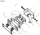
- the inventive lock system (1) enabling to switch on a defective locking mechanism essentially comprises:
- the inventive lock system (1) has a shaft (2) with a movable and conductive characteristic which carries out the locking process.
- the shaft (2) - which is preferably in the form of cylinder - has a conductor (3) that is located inside a recess opened on the outer surface thereof and enables transmission of electric current, extends along thereof.
- a conducting strip can be used for this conductor (3) as well.
- An insulation material (4) providing electrical insulation is placed between the conductor (3) and the shaft (2).
- the shaft (2) can move bidirectionally in the horizontal plane by means of the action mechanism (5).
- the action mechanism (5) has a receiver which can take command in a wired or wireless way, control the action. By commands to be issued to this receiver, the shaft (2) can carry out the processes of locking and unlocking by moving forwards-backwards in horizontal plane.
- the said receiver can also control current transition over the shaft (2) and the conductor (3), it can act as a switch.
- the shaft (2) is moved horizontally together with the action mechanism (5) so as to carry out the locking process.
- the locking process is realized upon the end portion of the shaft (2) in the direction of movement enters the lock input-output housing (6) corresponding to the end portion in the direction of movement where the shaft (2) moves.
- the lock input-output housing (6) is located on the upper section of lock input-output housing (7) which is made of a conductive material.
- the lower section of lock input-output housing (8) can be inserted to the place where the inventive lock system (1) will be fitted upon being mounted.
- the lower section of lock input-output housing (8) has holes (13) which can melt by heat, and where the connecting members (9) preferably in the form of screw and made of delrin plastic can be placed.
- the connecting member (9) has high strength at normal temperatures, it has the characteristic of breaking by melting at high temperatures.
- the connecting member (9) extends until the upper section of lock input-output housing (7) by passing through the holes (13) of the lower section of lock input-output housing (8).
- the lower section of lock input-output housing (8) and the upper section of lock input-output housing (7) are combined.
- resistance block (10) which surrounds the connecting members (9) between the lower section of lock input-output housing (8) and the upper section of lock input-output housing (7) combined by means of the connecting members (9).
- the resistance block (10) can reach high temperatures upon getting warmer when current passes through the terminal ends of the resistance block (10).
- the flexible piece (11) which enables the electrical connection between the conductor (3) and the resistance block (10).
- the flexible piece (11) with conductive characteristic which extends from the aperture (17) on the lower part of the upper section of lock input-output housing (7) to the lock input-output housing (6) in the form of a protrusion, establishes the electrical connection between a terminal end of the resistance block (10) and the conductor (3) by contacting the conductor (3).
- insulating plates (14) can be preferably used between the upper section of lock input-output housing (7) and the flexible piece (11), between the flexible piece (11) and the resistance block (10), and between the resistance block (10) and the lower section of lock input-output housing (8).
- the present invention enables to unlock upon the lock mechanism is separated when the lock cannot be opened as a result of an undesired entrapment in the lock mechanism or any problem in the lock system (1). Therefore, a signal is sent to the receiver by the user.
- This signal can be a signal that can be protected by password.
- processes desired can be carried out by entering password by means of a keypad located on the lock system (1).
- the shaft (2) is in contact with the upper section of lock input-output housing (7) and electrical conduction is provided between thereof.
- the conductive balls (15) ensure that the contact between the shaft (2) and the conductive balls (15) is provided tightly upon being pushed towards the lock input-output housing (6) by means of the springs (16).
- screws (1) which can be inserted from lateral sections of the upper section of lock input-output housing (7) can be used in order to reach the conductive balls (15) and the springs (16) more easily and provide mounting convenience.
- the resistance block (10) gets heated after current passes through the resistance block (10).
- the resistance block (10) heated enables to separate the upper section of lock input-output housing (7) and the lower section of lock input-output housing (8) by melting the connecting members (9) and allows unlocking.
- an alternative connecting member (9) - which combines the upper section of lock input-output housing (7) and the lower section of lock input-output housing (8), loses its form when current passes over it - is used without needing the resistance block (10). It can be ensured to separate the upper section of lock input-output housing (7) and the lower section of lock input-output housing (8) by passing current over the alternative connecting member (9) directly.
- the potential difference on the shaft (2) is transmitted to a terminal end of the resistance block (10) by means of a cable passing through a channel opened inside the upper section of lock input-output housing (7).
- the upper section of lock input-output housing (7) can be preferably coated with a conductive material in order to ensure electrical insulation.
Landscapes
- Business, Economics & Management (AREA)
- Emergency Management (AREA)
- Engineering & Computer Science (AREA)
- Physics & Mathematics (AREA)
- Electromagnetism (AREA)
- Structural Engineering (AREA)
- Mechanical Engineering (AREA)
- Lock And Its Accessories (AREA)
- Details Of Connecting Devices For Male And Female Coupling (AREA)
- Switch Cases, Indication, And Locking (AREA)
Claims (8)
- Système de verrouillage (1) qui permet de se déverrouiller suite à la séparation du mécanisme de verrouillage lorsque le verrou ne peut pas être ouvert suite à un coincement non souhaité dans le mécanisme de verrouillage ou tout problème dans le mécanisme de verrouillage, le système de verrouillage (1) comprenant :- au moins un arbre (2) qui réalise le processus de verrouillage, est mobile et présente une conductivité électrique ;- au moins un boîtier d'entrée et de sortie de verrou (6) dans lequel l'arbre (2) entre suite au déplacement et permet le processus de verrouillage ;- au moins une section supérieure du boîtier d'entrée et de sortie de verrou (7) qui présente le boîtier d'entrée et de sortie de verrou (6) sur celle-ci ;- au moins une section inférieure du boîtier d'entrée et de sortie de verrou (8) qui permet à la section supérieure du boîtier d'entrée et de sortie de verrou (7) d'être montée à un emplacement souhaité ;- au moins un élément de connexion (9) qui connecte la section supérieure du boîtier d'entrée et de sortie de verrou (7) et la section inférieure du boîtier d'entrée et de sortie de verrou (8) ;le système de verrouillage (1) étant essentiellement caractérisé par :- au moins un conducteur (3) qui est situé dans un évidement qui est de préférence ouvert sur la surface de l'arbre (2), qui permet de transmettre un courant électrique ;- au moins un matériau isolant (4) qui fournit l'isolation entre l'arbre (2) et le conducteur (3) ;- au moins un mécanisme d'action (5) qui permet l'action de l'arbre (2) et commande le passage du courant sur l'arbre (2) peut prendre la commande sur un récepteur de manière filaire ou sans fil, l'arbre (2) entrant dans le boîtier d'entrée et de sortie de verrou (6) suite au déplacement par le mécanisme d'action (5) ;- la section supérieure du boîtier d'entrée et de sortie de verrou (7) étant constituée d'un matériau conducteur ;- au moins un bloc de résistance (10) présentant une extrémité de borne et une autre extrémité, qui est située entre la section supérieure du boîtier d'entrée et de sortie de verrou (7) et la section inférieure du boîtier d'entrée et de sortie de verrou (8), au travers duquel l'au moins un élément de connexion (9) passe, et qui peut atteindre de hautes températures lorsque le courant le parcourt ;- une extrémité de l'arbre (2) étant adaptée pour être raccordée à une borne d'une source d'alimentation présentant ladite borne et un autre pôle ;- une extrémité du conducteur (3) étant adaptée pour être raccordée à l'autre pôle de la source d'alimentation, après que le récepteur a pris un signal envoyé au récepteur par un utilisateur, il complète un circuit entre l'arbre (2) et le conducteur (3) et crée ensuite une différence de potentiel entre l'arbre (2) et le conducteur (3) ;- une connexion électrique étant adaptée pour être établie entre l'arbre (2) et l'extrémité de borne du bloc de résistance (10) ;- au moins une pièce flexible (11), présentant une conductivité électrique, qui permet la connexion électrique entre le conducteur (3) et l'autre extrémité du bloc de résistance (10) ;- au moins une ouverture (17) au travers de laquelle la pièce flexible (11) passe et s'étend sous la forme d'une saillie, et qui est située dans la partie inférieure de la section supérieure du boîtier d'entrée et de sortie de verrou (7) ;- l'au moins un élément de connexion (9) perdant sa forme à température élevée ;- le bloc de résistance se mettant à chauffer après que le courant a passé au travers du bloc de résistance (10), le bloc de résistance (10) chauffé permettant de séparer la section supérieure du boîtier d'entrée et de sortie de verrou (7) et la section inférieure de boîtier d'entrée et de sortie de verrou (8) par fusion de l'au moins un élément de connexion (9) et permettant le déverrouillage.
- Système de verrouillage (1) selon la revendication 1, caractérisé par au moins un conducteur (3) qui est situé sur la partie inférieure de l'arbre (2) - qui est de préférence en forme de cylindre - et permet la transmission du courant électrique, peut être sous la forme d'une bande s'étendant le long de l'arbre cylindrique (2).
- Système de verrouillage (1) selon l'une quelconque des revendications précédentes, caractérisé par au moins un trou de montage (18) qui est situé sur la section inférieure du boîtier d'entrée et de sortie de verrou (8), permet au verrou d'être monté sur l'emplacement où il sera inséré.
- Système de verrouillage (1) selon l'une quelconque des revendications précédentes, caractérisé par au moins un appareil de montage (12) qui permet à la section inférieure du boîtier d'entrée et de sortie de verrou (8) d'être montée à l'emplacement souhaité.
- Système de verrouillage (1) selon l'une quelconque des revendications précédentes, caractérisé par l'élément de connexion (9) qui connecte la section supérieure du boîtier d'entrée et de sortie de verrou (7) et la section inférieure du boîtier d'entrée et de sortie de verrou (8), perd sa forme lorsque le courant le parcourt.
- Système de verrouillage (1) selon l'une quelconque des revendications précédentes, caractérisé par au moins un trou (13) qui est situé dans la section inférieure du boîtier d'entrée et de sortie de verrou (8), permet de placer les éléments de connexion (9) qui peuvent fondre de par la température.
- Système de verrouillage (1) selon l'une quelconque des revendications précédentes, caractérisé par au moins une balle conductrice (15) qui est située dans le boîtier d'entrée et de sortie de verrou (6), permet la conduction électrique entre l'arbre (2) et la section supérieure du boîtier d'entrée et de sortie de verrou (7).
- Système de verrouillage (1) selon l'une quelconque des revendications précédentes, caractérisé par au moins un ressort (16) qui permet de fournir étroitement le contact entre l'arbre (2) et les balles conductrices (15) suite à la poussée vers le boîtier d'entrée et de sortie de verrou (6).
Applications Claiming Priority (2)
| Application Number | Priority Date | Filing Date | Title |
|---|---|---|---|
| TR201405348 | 2014-05-13 | ||
| PCT/TR2015/000201 WO2015174946A1 (fr) | 2014-05-13 | 2015-05-13 | Système de verrouillage |
Publications (2)
| Publication Number | Publication Date |
|---|---|
| EP3143224A1 EP3143224A1 (fr) | 2017-03-22 |
| EP3143224B1 true EP3143224B1 (fr) | 2018-07-11 |
Family
ID=53404836
Family Applications (1)
| Application Number | Title | Priority Date | Filing Date |
|---|---|---|---|
| EP15729591.6A Not-in-force EP3143224B1 (fr) | 2014-05-13 | 2015-05-13 | Système de verrouillage |
Country Status (4)
| Country | Link |
|---|---|
| US (1) | US20160237718A1 (fr) |
| EP (1) | EP3143224B1 (fr) |
| EA (1) | EA032686B1 (fr) |
| WO (1) | WO2015174946A1 (fr) |
Families Citing this family (2)
| Publication number | Priority date | Publication date | Assignee | Title |
|---|---|---|---|---|
| CN109209041A (zh) * | 2018-08-29 | 2019-01-15 | 珠海优特电力科技股份有限公司 | 锁具、锁具系统以及锁具的控制方法、控制装置 |
| DE102020102323A1 (de) | 2020-01-30 | 2021-08-05 | Martin Lehmann GmbH & Co. Kommanditgesellschaft | Verriegelungsmechanik und Behälter |
Family Cites Families (5)
| Publication number | Priority date | Publication date | Assignee | Title |
|---|---|---|---|---|
| US3890608A (en) * | 1972-10-11 | 1975-06-17 | Hager & Sons Hinge Mfg | Door monitoring and controlling device for a security system |
| US5576581A (en) * | 1993-11-17 | 1996-11-19 | Solid State Securities, Inc. | Door control system and release mechanism |
| GB2307712B (en) * | 1995-11-30 | 1999-10-13 | Chen Fu Hsiang | Latch Device |
| GB2441143B (en) * | 2006-08-26 | 2009-03-11 | Stephen Worthy | A keep assembly |
| EP2195802B8 (fr) * | 2007-10-05 | 2013-02-20 | E.J. Brooks Company | Sceau de sécurité à boulon doté d'un module électronique réutilisable et d'un boulon |
-
2015
- 2015-05-13 EP EP15729591.6A patent/EP3143224B1/fr not_active Not-in-force
- 2015-05-13 EA EA201690542A patent/EA032686B1/ru not_active IP Right Cessation
- 2015-05-13 US US15/027,081 patent/US20160237718A1/en not_active Abandoned
- 2015-05-13 WO PCT/TR2015/000201 patent/WO2015174946A1/fr not_active Ceased
Non-Patent Citations (1)
| Title |
|---|
| None * |
Also Published As
| Publication number | Publication date |
|---|---|
| EA201690542A1 (ru) | 2017-04-28 |
| EA032686B1 (ru) | 2019-07-31 |
| WO2015174946A1 (fr) | 2015-11-19 |
| US20160237718A1 (en) | 2016-08-18 |
| EP3143224A1 (fr) | 2017-03-22 |
Similar Documents
| Publication | Publication Date | Title |
|---|---|---|
| EP3703096B1 (fr) | Dispositif de verrouillage pour dispositif d'actionnement de disjoncteur | |
| US9396894B2 (en) | Conductivity power connection | |
| EP3143224B1 (fr) | Système de verrouillage | |
| EP3262906A1 (fr) | Module de porte et utilisations correspondantes | |
| US5791178A (en) | Electrical transmission path for electrical and electro-mechanical locks | |
| FI3064694T3 (fi) | Virransyöttö ovi- tai ikkunalehteen | |
| US11638358B2 (en) | High-voltage device | |
| EP3162989A1 (fr) | Dispositif de commande d'accès | |
| US9865407B2 (en) | Interlock apparatus of ring main unit | |
| JP2010209974A (ja) | 入退室管理装置 | |
| CN104779100A (zh) | 一种开关柜用接地开关操作联锁机构 | |
| CN107002436A (zh) | 用于在壁和可相对于该壁枢转的翼扇之间传输电功率和/或信号的方法和装置 | |
| KR101295694B1 (ko) | 트랩트 키 스위치 | |
| KR20200017128A (ko) | 무선통신으로 열리는 도아 개폐장치 | |
| FI20185799A1 (fi) | Laitteisto ja menetelmä elektronisen ovilukon etäavaamiseksi | |
| US3263040A (en) | Pressure operated circuit controlling devices operable on relative movement between two elements | |
| US20210313126A1 (en) | Detachable knob for actuating switchgear, and a switchgear device incorporating the detachable knob | |
| KR101569646B1 (ko) | 전류 제어에 기반하여 차폐되는 배전반 | |
| US20150115617A1 (en) | Apparatus and method for wirelessly transmitting data from a vehicle latch | |
| CN106910653A (zh) | 带电磁信号控制的安全钥匙联锁 | |
| CN107845537B (zh) | 一种电动接地刀闭锁装置 | |
| CN114613619B (zh) | 一种开关防误接线保护装置 | |
| CN108475593B (zh) | 用于断开接触器的断路器设备和装置 | |
| US11840151B2 (en) | Device for encapsulating and interrupting the power supply of a battery | |
| CN114613623B (zh) | 一种开关防误接线装置 |
Legal Events
| Date | Code | Title | Description |
|---|---|---|---|
| STAA | Information on the status of an ep patent application or granted ep patent |
Free format text: STATUS: THE INTERNATIONAL PUBLICATION HAS BEEN MADE |
|
| PUAI | Public reference made under article 153(3) epc to a published international application that has entered the european phase |
Free format text: ORIGINAL CODE: 0009012 |
|
| STAA | Information on the status of an ep patent application or granted ep patent |
Free format text: STATUS: REQUEST FOR EXAMINATION WAS MADE |
|
| 17P | Request for examination filed |
Effective date: 20160330 |
|
| AK | Designated contracting states |
Kind code of ref document: A1 Designated state(s): AL AT BE BG CH CY CZ DE DK EE ES FI FR GB GR HR HU IE IS IT LI LT LU LV MC MK MT NL NO PL PT RO RS SE SI SK SM TR |
|
| AX | Request for extension of the european patent |
Extension state: BA ME |
|
| RIN1 | Information on inventor provided before grant (corrected) |
Inventor name: VARDAR, GOKHAN |
|
| DAV | Request for validation of the european patent (deleted) | ||
| DAX | Request for extension of the european patent (deleted) | ||
| GRAP | Despatch of communication of intention to grant a patent |
Free format text: ORIGINAL CODE: EPIDOSNIGR1 |
|
| STAA | Information on the status of an ep patent application or granted ep patent |
Free format text: STATUS: GRANT OF PATENT IS INTENDED |
|
| INTG | Intention to grant announced |
Effective date: 20180403 |
|
| GRAA | (expected) grant |
Free format text: ORIGINAL CODE: 0009210 |
|
| STAA | Information on the status of an ep patent application or granted ep patent |
Free format text: STATUS: THE PATENT HAS BEEN GRANTED |
|
| AK | Designated contracting states |
Kind code of ref document: B1 Designated state(s): AL AT BE BG CH CY CZ DE DK EE ES FI FR GB GR HR HU IE IS IT LI LT LU LV MC MK MT NL NO PL PT RO RS SE SI SK SM TR |
|
| REG | Reference to a national code |
Ref country code: GB Ref legal event code: FG4D |
|
| REG | Reference to a national code |
Ref country code: CH Ref legal event code: EP |
|
| REG | Reference to a national code |
Ref country code: AT Ref legal event code: REF Ref document number: 1017043 Country of ref document: AT Kind code of ref document: T Effective date: 20180715 |
|
| GRAS | Grant fee paid |
Free format text: ORIGINAL CODE: EPIDOSNIGR3 |
|
| REG | Reference to a national code |
Ref country code: DE Ref legal event code: R096 Ref document number: 602015013455 Country of ref document: DE |
|
| REG | Reference to a national code |
Ref country code: IE Ref legal event code: FG4D |
|
| REG | Reference to a national code |
Ref country code: NL Ref legal event code: FP |
|
| RAP2 | Party data changed (patent owner data changed or rights of a patent transferred) |
Owner name: TURKCELL ILETISIM HIZMETLERI ANONIM SIRKETI |
|
| REG | Reference to a national code |
Ref country code: LT Ref legal event code: MG4D |
|
| REG | Reference to a national code |
Ref country code: AT Ref legal event code: MK05 Ref document number: 1017043 Country of ref document: AT Kind code of ref document: T Effective date: 20180711 |
|
| PG25 | Lapsed in a contracting state [announced via postgrant information from national office to epo] |
Ref country code: LT Free format text: LAPSE BECAUSE OF FAILURE TO SUBMIT A TRANSLATION OF THE DESCRIPTION OR TO PAY THE FEE WITHIN THE PRESCRIBED TIME-LIMIT Effective date: 20180711 Ref country code: RS Free format text: LAPSE BECAUSE OF FAILURE TO SUBMIT A TRANSLATION OF THE DESCRIPTION OR TO PAY THE FEE WITHIN THE PRESCRIBED TIME-LIMIT Effective date: 20180711 Ref country code: PL Free format text: LAPSE BECAUSE OF FAILURE TO SUBMIT A TRANSLATION OF THE DESCRIPTION OR TO PAY THE FEE WITHIN THE PRESCRIBED TIME-LIMIT Effective date: 20180711 Ref country code: AT Free format text: LAPSE BECAUSE OF FAILURE TO SUBMIT A TRANSLATION OF THE DESCRIPTION OR TO PAY THE FEE WITHIN THE PRESCRIBED TIME-LIMIT Effective date: 20180711 Ref country code: IS Free format text: LAPSE BECAUSE OF FAILURE TO SUBMIT A TRANSLATION OF THE DESCRIPTION OR TO PAY THE FEE WITHIN THE PRESCRIBED TIME-LIMIT Effective date: 20181111 Ref country code: NO Free format text: LAPSE BECAUSE OF FAILURE TO SUBMIT A TRANSLATION OF THE DESCRIPTION OR TO PAY THE FEE WITHIN THE PRESCRIBED TIME-LIMIT Effective date: 20181011 Ref country code: SE Free format text: LAPSE BECAUSE OF FAILURE TO SUBMIT A TRANSLATION OF THE DESCRIPTION OR TO PAY THE FEE WITHIN THE PRESCRIBED TIME-LIMIT Effective date: 20180711 Ref country code: GR Free format text: LAPSE BECAUSE OF FAILURE TO SUBMIT A TRANSLATION OF THE DESCRIPTION OR TO PAY THE FEE WITHIN THE PRESCRIBED TIME-LIMIT Effective date: 20181012 Ref country code: FI Free format text: LAPSE BECAUSE OF FAILURE TO SUBMIT A TRANSLATION OF THE DESCRIPTION OR TO PAY THE FEE WITHIN THE PRESCRIBED TIME-LIMIT Effective date: 20180711 Ref country code: BG Free format text: LAPSE BECAUSE OF FAILURE TO SUBMIT A TRANSLATION OF THE DESCRIPTION OR TO PAY THE FEE WITHIN THE PRESCRIBED TIME-LIMIT Effective date: 20181011 |
|
| PG25 | Lapsed in a contracting state [announced via postgrant information from national office to epo] |
Ref country code: HR Free format text: LAPSE BECAUSE OF FAILURE TO SUBMIT A TRANSLATION OF THE DESCRIPTION OR TO PAY THE FEE WITHIN THE PRESCRIBED TIME-LIMIT Effective date: 20180711 Ref country code: LV Free format text: LAPSE BECAUSE OF FAILURE TO SUBMIT A TRANSLATION OF THE DESCRIPTION OR TO PAY THE FEE WITHIN THE PRESCRIBED TIME-LIMIT Effective date: 20180711 Ref country code: AL Free format text: LAPSE BECAUSE OF FAILURE TO SUBMIT A TRANSLATION OF THE DESCRIPTION OR TO PAY THE FEE WITHIN THE PRESCRIBED TIME-LIMIT Effective date: 20180711 |
|
| REG | Reference to a national code |
Ref country code: DE Ref legal event code: R097 Ref document number: 602015013455 Country of ref document: DE |
|
| PG25 | Lapsed in a contracting state [announced via postgrant information from national office to epo] |
Ref country code: CZ Free format text: LAPSE BECAUSE OF FAILURE TO SUBMIT A TRANSLATION OF THE DESCRIPTION OR TO PAY THE FEE WITHIN THE PRESCRIBED TIME-LIMIT Effective date: 20180711 Ref country code: RO Free format text: LAPSE BECAUSE OF FAILURE TO SUBMIT A TRANSLATION OF THE DESCRIPTION OR TO PAY THE FEE WITHIN THE PRESCRIBED TIME-LIMIT Effective date: 20180711 Ref country code: IT Free format text: LAPSE BECAUSE OF FAILURE TO SUBMIT A TRANSLATION OF THE DESCRIPTION OR TO PAY THE FEE WITHIN THE PRESCRIBED TIME-LIMIT Effective date: 20180711 Ref country code: ES Free format text: LAPSE BECAUSE OF FAILURE TO SUBMIT A TRANSLATION OF THE DESCRIPTION OR TO PAY THE FEE WITHIN THE PRESCRIBED TIME-LIMIT Effective date: 20180711 Ref country code: EE Free format text: LAPSE BECAUSE OF FAILURE TO SUBMIT A TRANSLATION OF THE DESCRIPTION OR TO PAY THE FEE WITHIN THE PRESCRIBED TIME-LIMIT Effective date: 20180711 |
|
| PLBE | No opposition filed within time limit |
Free format text: ORIGINAL CODE: 0009261 |
|
| STAA | Information on the status of an ep patent application or granted ep patent |
Free format text: STATUS: NO OPPOSITION FILED WITHIN TIME LIMIT |
|
| PG25 | Lapsed in a contracting state [announced via postgrant information from national office to epo] |
Ref country code: DK Free format text: LAPSE BECAUSE OF FAILURE TO SUBMIT A TRANSLATION OF THE DESCRIPTION OR TO PAY THE FEE WITHIN THE PRESCRIBED TIME-LIMIT Effective date: 20180711 Ref country code: SK Free format text: LAPSE BECAUSE OF FAILURE TO SUBMIT A TRANSLATION OF THE DESCRIPTION OR TO PAY THE FEE WITHIN THE PRESCRIBED TIME-LIMIT Effective date: 20180711 Ref country code: SM Free format text: LAPSE BECAUSE OF FAILURE TO SUBMIT A TRANSLATION OF THE DESCRIPTION OR TO PAY THE FEE WITHIN THE PRESCRIBED TIME-LIMIT Effective date: 20180711 |
|
| 26N | No opposition filed |
Effective date: 20190412 |
|
| PGFP | Annual fee paid to national office [announced via postgrant information from national office to epo] |
Ref country code: NL Payment date: 20190521 Year of fee payment: 5 |
|
| PGFP | Annual fee paid to national office [announced via postgrant information from national office to epo] |
Ref country code: IE Payment date: 20190522 Year of fee payment: 5 |
|
| PG25 | Lapsed in a contracting state [announced via postgrant information from national office to epo] |
Ref country code: SI Free format text: LAPSE BECAUSE OF FAILURE TO SUBMIT A TRANSLATION OF THE DESCRIPTION OR TO PAY THE FEE WITHIN THE PRESCRIBED TIME-LIMIT Effective date: 20180711 |
|
| PGFP | Annual fee paid to national office [announced via postgrant information from national office to epo] |
Ref country code: GB Payment date: 20190521 Year of fee payment: 5 |
|
| REG | Reference to a national code |
Ref country code: DE Ref legal event code: R119 Ref document number: 602015013455 Country of ref document: DE |
|
| REG | Reference to a national code |
Ref country code: CH Ref legal event code: PL |
|
| PG25 | Lapsed in a contracting state [announced via postgrant information from national office to epo] |
Ref country code: LI Free format text: LAPSE BECAUSE OF NON-PAYMENT OF DUE FEES Effective date: 20190531 Ref country code: CH Free format text: LAPSE BECAUSE OF NON-PAYMENT OF DUE FEES Effective date: 20190531 Ref country code: MC Free format text: LAPSE BECAUSE OF FAILURE TO SUBMIT A TRANSLATION OF THE DESCRIPTION OR TO PAY THE FEE WITHIN THE PRESCRIBED TIME-LIMIT Effective date: 20180711 |
|
| REG | Reference to a national code |
Ref country code: BE Ref legal event code: MM Effective date: 20190531 |
|
| PG25 | Lapsed in a contracting state [announced via postgrant information from national office to epo] |
Ref country code: LU Free format text: LAPSE BECAUSE OF NON-PAYMENT OF DUE FEES Effective date: 20190513 |
|
| PG25 | Lapsed in a contracting state [announced via postgrant information from national office to epo] |
Ref country code: TR Free format text: LAPSE BECAUSE OF FAILURE TO SUBMIT A TRANSLATION OF THE DESCRIPTION OR TO PAY THE FEE WITHIN THE PRESCRIBED TIME-LIMIT Effective date: 20180711 |
|
| PG25 | Lapsed in a contracting state [announced via postgrant information from national office to epo] |
Ref country code: DE Free format text: LAPSE BECAUSE OF NON-PAYMENT OF DUE FEES Effective date: 20191203 |
|
| PG25 | Lapsed in a contracting state [announced via postgrant information from national office to epo] |
Ref country code: BE Free format text: LAPSE BECAUSE OF NON-PAYMENT OF DUE FEES Effective date: 20190531 |
|
| PG25 | Lapsed in a contracting state [announced via postgrant information from national office to epo] |
Ref country code: PT Free format text: LAPSE BECAUSE OF FAILURE TO SUBMIT A TRANSLATION OF THE DESCRIPTION OR TO PAY THE FEE WITHIN THE PRESCRIBED TIME-LIMIT Effective date: 20181111 Ref country code: FR Free format text: LAPSE BECAUSE OF NON-PAYMENT OF DUE FEES Effective date: 20190531 |
|
| REG | Reference to a national code |
Ref country code: NL Ref legal event code: MM Effective date: 20200601 |
|
| PG25 | Lapsed in a contracting state [announced via postgrant information from national office to epo] |
Ref country code: NL Free format text: LAPSE BECAUSE OF NON-PAYMENT OF DUE FEES Effective date: 20200601 |
|
| GBPC | Gb: european patent ceased through non-payment of renewal fee |
Effective date: 20200513 |
|
| PG25 | Lapsed in a contracting state [announced via postgrant information from national office to epo] |
Ref country code: GB Free format text: LAPSE BECAUSE OF NON-PAYMENT OF DUE FEES Effective date: 20200513 Ref country code: IE Free format text: LAPSE BECAUSE OF NON-PAYMENT OF DUE FEES Effective date: 20200513 |
|
| PG25 | Lapsed in a contracting state [announced via postgrant information from national office to epo] |
Ref country code: CY Free format text: LAPSE BECAUSE OF FAILURE TO SUBMIT A TRANSLATION OF THE DESCRIPTION OR TO PAY THE FEE WITHIN THE PRESCRIBED TIME-LIMIT Effective date: 20180711 |
|
| PG25 | Lapsed in a contracting state [announced via postgrant information from national office to epo] |
Ref country code: HU Free format text: LAPSE BECAUSE OF FAILURE TO SUBMIT A TRANSLATION OF THE DESCRIPTION OR TO PAY THE FEE WITHIN THE PRESCRIBED TIME-LIMIT; INVALID AB INITIO Effective date: 20150513 Ref country code: MT Free format text: LAPSE BECAUSE OF FAILURE TO SUBMIT A TRANSLATION OF THE DESCRIPTION OR TO PAY THE FEE WITHIN THE PRESCRIBED TIME-LIMIT Effective date: 20180711 |
|
| PG25 | Lapsed in a contracting state [announced via postgrant information from national office to epo] |
Ref country code: MK Free format text: LAPSE BECAUSE OF FAILURE TO SUBMIT A TRANSLATION OF THE DESCRIPTION OR TO PAY THE FEE WITHIN THE PRESCRIBED TIME-LIMIT Effective date: 20180711 |