EP3143231B1 - Dispositif de commande pour un actionneur de porte - Google Patents
Dispositif de commande pour un actionneur de porte Download PDFInfo
- Publication number
- EP3143231B1 EP3143231B1 EP15792031.5A EP15792031A EP3143231B1 EP 3143231 B1 EP3143231 B1 EP 3143231B1 EP 15792031 A EP15792031 A EP 15792031A EP 3143231 B1 EP3143231 B1 EP 3143231B1
- Authority
- EP
- European Patent Office
- Prior art keywords
- door
- door operator
- microprocessor
- operator
- display screen
- Prior art date
- Legal status (The legal status is an assumption and is not a legal conclusion. Google has not performed a legal analysis and makes no representation as to the accuracy of the status listed.)
- Active
Links
Images






Classifications
-
- E—FIXED CONSTRUCTIONS
- E05—LOCKS; KEYS; WINDOW OR DOOR FITTINGS; SAFES
- E05F—DEVICES FOR MOVING WINGS INTO OPEN OR CLOSED POSITION; CHECKS FOR WINGS; WING FITTINGS NOT OTHERWISE PROVIDED FOR, CONCERNED WITH THE FUNCTIONING OF THE WING
- E05F15/00—Power-operated mechanisms for wings
- E05F15/70—Power-operated mechanisms for wings with automatic actuation
-
- E—FIXED CONSTRUCTIONS
- E05—LOCKS; KEYS; WINDOW OR DOOR FITTINGS; SAFES
- E05F—DEVICES FOR MOVING WINGS INTO OPEN OR CLOSED POSITION; CHECKS FOR WINGS; WING FITTINGS NOT OTHERWISE PROVIDED FOR, CONCERNED WITH THE FUNCTIONING OF THE WING
- E05F15/00—Power-operated mechanisms for wings
- E05F15/60—Power-operated mechanisms for wings using electrical actuators
- E05F15/603—Power-operated mechanisms for wings using electrical actuators using rotary electromotors
- E05F15/611—Power-operated mechanisms for wings using electrical actuators using rotary electromotors for swinging wings
- E05F15/63—Power-operated mechanisms for wings using electrical actuators using rotary electromotors for swinging wings operated by swinging arms
-
- E—FIXED CONSTRUCTIONS
- E05—LOCKS; KEYS; WINDOW OR DOOR FITTINGS; SAFES
- E05Y—INDEXING SCHEME ASSOCIATED WITH SUBCLASSES E05D AND E05F, RELATING TO CONSTRUCTION ELEMENTS, ELECTRIC CONTROL, POWER SUPPLY, POWER SIGNAL OR TRANSMISSION, USER INTERFACES, MOUNTING OR COUPLING, DETAILS, ACCESSORIES, AUXILIARY OPERATIONS NOT OTHERWISE PROVIDED FOR, APPLICATION THEREOF
- E05Y2400/00—Electronic control; Electrical power; Power supply; Power or signal transmission; User interfaces
- E05Y2400/10—Electronic control
- E05Y2400/36—Speed control, detection or monitoring
-
- E—FIXED CONSTRUCTIONS
- E05—LOCKS; KEYS; WINDOW OR DOOR FITTINGS; SAFES
- E05Y—INDEXING SCHEME ASSOCIATED WITH SUBCLASSES E05D AND E05F, RELATING TO CONSTRUCTION ELEMENTS, ELECTRIC CONTROL, POWER SUPPLY, POWER SIGNAL OR TRANSMISSION, USER INTERFACES, MOUNTING OR COUPLING, DETAILS, ACCESSORIES, AUXILIARY OPERATIONS NOT OTHERWISE PROVIDED FOR, APPLICATION THEREOF
- E05Y2400/00—Electronic control; Electrical power; Power supply; Power or signal transmission; User interfaces
- E05Y2400/10—Electronic control
- E05Y2400/45—Control modes
- E05Y2400/456—Control modes for programming, e.g. learning or AI [artificial intelligence]
-
- E—FIXED CONSTRUCTIONS
- E05—LOCKS; KEYS; WINDOW OR DOOR FITTINGS; SAFES
- E05Y—INDEXING SCHEME ASSOCIATED WITH SUBCLASSES E05D AND E05F, RELATING TO CONSTRUCTION ELEMENTS, ELECTRIC CONTROL, POWER SUPPLY, POWER SIGNAL OR TRANSMISSION, USER INTERFACES, MOUNTING OR COUPLING, DETAILS, ACCESSORIES, AUXILIARY OPERATIONS NOT OTHERWISE PROVIDED FOR, APPLICATION THEREOF
- E05Y2400/00—Electronic control; Electrical power; Power supply; Power or signal transmission; User interfaces
- E05Y2400/80—User interfaces
- E05Y2400/81—Feedback to user, e.g. tactile
- E05Y2400/818—Visual
- E05Y2400/82—Images; Symbols
-
- E—FIXED CONSTRUCTIONS
- E05—LOCKS; KEYS; WINDOW OR DOOR FITTINGS; SAFES
- E05Y—INDEXING SCHEME ASSOCIATED WITH SUBCLASSES E05D AND E05F, RELATING TO CONSTRUCTION ELEMENTS, ELECTRIC CONTROL, POWER SUPPLY, POWER SIGNAL OR TRANSMISSION, USER INTERFACES, MOUNTING OR COUPLING, DETAILS, ACCESSORIES, AUXILIARY OPERATIONS NOT OTHERWISE PROVIDED FOR, APPLICATION THEREOF
- E05Y2400/00—Electronic control; Electrical power; Power supply; Power or signal transmission; User interfaces
- E05Y2400/80—User interfaces
- E05Y2400/85—User input means
- E05Y2400/856—Actuation thereof
- E05Y2400/858—Actuation thereof by body parts, e.g. by feet
- E05Y2400/86—Actuation thereof by body parts, e.g. by feet by hand
-
- E—FIXED CONSTRUCTIONS
- E05—LOCKS; KEYS; WINDOW OR DOOR FITTINGS; SAFES
- E05Y—INDEXING SCHEME ASSOCIATED WITH SUBCLASSES E05D AND E05F, RELATING TO CONSTRUCTION ELEMENTS, ELECTRIC CONTROL, POWER SUPPLY, POWER SIGNAL OR TRANSMISSION, USER INTERFACES, MOUNTING OR COUPLING, DETAILS, ACCESSORIES, AUXILIARY OPERATIONS NOT OTHERWISE PROVIDED FOR, APPLICATION THEREOF
- E05Y2800/00—Details, accessories and auxiliary operations not otherwise provided for
-
- E—FIXED CONSTRUCTIONS
- E05—LOCKS; KEYS; WINDOW OR DOOR FITTINGS; SAFES
- E05Y—INDEXING SCHEME ASSOCIATED WITH SUBCLASSES E05D AND E05F, RELATING TO CONSTRUCTION ELEMENTS, ELECTRIC CONTROL, POWER SUPPLY, POWER SIGNAL OR TRANSMISSION, USER INTERFACES, MOUNTING OR COUPLING, DETAILS, ACCESSORIES, AUXILIARY OPERATIONS NOT OTHERWISE PROVIDED FOR, APPLICATION THEREOF
- E05Y2900/00—Application of doors, windows, wings or fittings thereof
- E05Y2900/10—Application of doors, windows, wings or fittings thereof for buildings or parts thereof
- E05Y2900/13—Type of wing
- E05Y2900/132—Doors
Definitions
- a door operator for a door is described and, more particularly, a door operator including interactive control and monitoring for selectively setting operating parameters of the door.
- door operators The purpose of door operators is to open and close a door.
- Automatic door operators are used on public buildings and residences to allow for access by the physically disabled or where manual operation of the door may be inconvenient to users.
- public facilities it is a required American National Standard that doors which provide ingress and egress have the ability to open automatically in order to allow handicapped people passage through the doorway.
- a variety of electromechanical automatic door operators are known.
- a typical electromechanical door operator includes an electric motor and a linkage assembly for operatively coupling the drive shaft of the motor to a door so that the door will be opened and closed when the drive shaft rotates.
- Activation of the door operator is initiated by means of an electric signal generated in a variety of ways such as, for example, a pressure switch, an ultrasonic or photoelectric presence sensor, motion sensors, radio transmitters, wall switches, and the like.
- the door may then be closed under power or with a door closer.
- a conventional door closer uses an internal spring mechanism which is compressed during the opening of the door for storing sufficient energy so that the door can be returned to a closed position without the input of additional electrical energy.
- the automatic, powered opening system and door closer are controlled by switches, sensors and valves.
- technicians installing door operators perform set up and adjustment of different parameters. Each time, the technician must gain access to a control board of the door operator, usually by removing a cover or gate operator housing, to make the desired adjustments.
- Commissioning and setting door operators and closers is typically done using one or more of the following methods: LED indicators light up and installer waits for button presses to change settings; seven (7) segment displays show a code and installer waits for button presses to change settings that may change the codes on the display (a combination of flashes, alternate lights or colors might be used to indicate progression through menu items or a change in values); a scrolling alphanumeric display; or an alphanumeric display with region buttons or set buttons similar to an MFD (multi-function display) common in military or aviation.
- MFD multi-function display
- WO2004/053269A1 discloses a system for detecting the position of a moveable barrier as it travels between open and closed positions.
- the system includes an indicator module positioned away from a door operator mechanism and the moveable barrier, in a position where the user has access to the module but is not in a position to directly see the operational status of the moveable barrier.
- the indicator module comprises a user interface coupled to an indicator controller which communicates via a link with the door operator controller and includes a plurality of indication devices, which may be a video display having touch screen capabilities.
- a further object of the invention is to provide an improved apparatus including a graphical user interface with touch capability which can be used on any door operator or closer that requires input from a user for adjusting settings or commissioning the unit.
- a method according to claim 12 is also provided for adjusting parameters within a door operator.
- the user communicates with a door operator through a user input.
- An interface connected to the door operator, a circuitry is configured to receive a command signal from the user, a controller for deriving a control signal from the command signal, and a display configured to present the data in a graphical and alphanumeric format.
- the data comprises a set of information from a sensor connected to the door operator.
- the present invention is directed to a door operator comprising a door operator housing, a door driver for opening and closing a door, a controller including a microprocessor connected to and controlling the door driver, and a graphical user interface embedded in the door operator during production and hidden under a cover which serves to surround and enclose the components of the door operator, and accessible by removal of the cover or at least a portion of the door operator housing, the graphical user interface comprising a pixel display screen capable of graphics and augmented with a planar touch select overlay being the user input device coupled to the microprocessor to display information stored in the controller and to receive instructions selected from the display screen by a user.
- the door operator includes a memory module coupled to the microprocessor and storing code executed by the microprocessor, wherein the microprocessor under control of the code displays to the user various menu items on the graphical user interface display and enables the user to select among the menu items using the display screen with touch select input such that the microprocessor derives a control signal.
- the door operator further includes circuitry configured to receive the control signal from the microprocessor and to carry the control signal to the door driver.
- the term "open position" for a door means a door position other than a closed position, including any position between the closed position and a fully-open position as limited only by structure around the door frame, which can be up to 180 degrees from the closed position.
- a door operator not according to the present invention is shown in FIG. 1 and generally designated at 40.
- the door operator 40 is mounted adjacent to a door 42 in a door frame 44 for movement of the door 42 relative to the frame 44 between a closed position and an open position. For the purpose of this description, only the upper portion of the door 42 and the door frame 44 are shown.
- the door 42 is of a conventional type and is pivotally mounted to the frame 44 for movement from the closed position, as shown in FIG. 1 , to an open position for opening and closing an opening through a building wall 48 to allow a user to travel from one side of the wall 48 to the other side of the wall 48.
- the door operator 40 comprises a back plate 50, a motor assembly 52, a door closer assembly 54 including a linkage assembly 56 for operably coupling the door operator 40 to the door 42, and a controller 58.
- the back plate 50 has substantially flat rear wall 60 and end walls 62.
- the back plate 50 is securely mounted to the upper edge of door frame 44 using mounting bolts (not shown), or other fasteners.
- the back plate 50 extends generally horizontally with respect to the door frame 44.
- the motor assembly 52, door closer assembly 54, and controller 58 are fixed to the back plate 50.
- a cover (not shown) attaches to the back plate 50.
- the cover serves to surround and enclose the components of the door operator 40 to reduce dirt and dust contamination, and to provide a more aesthetically pleasing appearance.
- back plate 50 is shown mounted directly to the door frame 44, the back plate 50 could be mounted to wall 48 adjacent the door frame 44 or concealed within the wall 48 or door frame 44.
- Concealed door operators are well known in the art of automatic door operators.
- a system and method is provided for sending and receiving information to and from the door operator 50 to allow for controlling, monitoring and adjusting information pertaining to operating parameters of the door operator.
- the control system assists a user, for example an installer, technician, service man or repair man to set, adjust, command, test, troubleshoot, configure, upgrade or monitor a door operator, as well as any other device connected to the same power grid.
- a door operator can be any system that controls a barrier to entry, an exit, or a view, for example, a door operator, a garage door opener, or the like.
- the barrier could be a door or window for a small entity, or a gate for a large entity, (i.e., a vehicle) which can swing out, slide open, or even roll upwards.
- the operator which moves the barrier or gate from an open position to a closed position, or vice versa, can be manual or automatic.
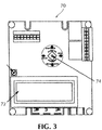
- a controller unit 70 not according to the invention, comprises a processor, e.g. a microprocessor or a microcontroller, with memory for storing instructions and data. Some of the memory is non-volatile, storing configuration information and program code.
- An LCD display screen 72 of the controller 70 displays various menus, icons, and other information to the user under direction of the processor. The display screen 72 displays information received or stored in the controller. Of course, any type of display may be implemented.
- the display screen 72 is self-illuminating to assist in dark work environments.
- the user can scroll through the menus and icons using an input device, for example, a joystick 74, which may include an internal push-to-activate switch.
- the processor is connected to the input device so that it can read the status of the input device. Moving the joystick 74 instructs the processor to cause the display to scroll through the menus. Pushing on the joystick 74 with an internal push-to-activate switch instructs the processor that the current menu items have been selected by the user.
- the controller 70 may derive power from the power grid. However, the controller 70 may also be battery-operated in case that a power failure occurs or is not plugged into a power source when using both sources of power.
- the controller 70 comprises a rechargeable battery so that the device may be operated without the need for a separate power source.
- the controller 70 also comprises a power cord that may be extended from the controller to access any available power grid.
- a power grid interface derives power from a power line and in turn supplies current to both the power supply and other circuitry.
- the power supply feeds power to various components of monitoring device including the rechargeable battery and CPU.
- the display screen 72 is configured to present data in a graphical and alphanumerical format.
- the controller 70 is capable of providing graphical and numerical depictions of the internal parameters of the door operator.
- the CPU communicates with the controller 70 to send information to the display screen 72.
- the controller 70 uses a combination of graphical representations, text messages, and light indicators to represent data.
- text messages on the screen 72 inform the user of real time events as they occur.
- the controller 70 may comprise light indicators that light up when a particular event takes place.
- the graphical or text representations will allow the technician to adjust or set the parameters. This is desirable in the industry as many users have different requirements for the use of their doors and technicians are required to make adjustments.
- the input interface along with joystick 74 control combined with internal components, such as a CPU and a memory, allow a user implementing the control system to receive, process, and send information.
- setup and adjustment of the inverter and door operator are performed with the joystick 74.
- the LCD screen 72 shows the feature to be adjusted and the setting.
- a small potentiometer (“pot") beside the LCD interface can be used to adjust the LCD screen contrast.
- the joystick is moved toward "MENU ⁇ UP” to scroll up or toward "MENU ⁇ DOWN” to scroll down.
- the joystick is moved toward "INCR ⁇ " to increase the value or toward " ⁇ DECR” to decrease the value.
- the joystick is pushed inwardly.
- Some of the features that may be set and adjusted include hand of the door, whether left hand or right hand mounted.
- the mounting of the door is also designated as a push or pull, depending on the side of the door on which the unit is mounted.
- Obstruction detection and delay sensitivity may be adjusted.
- the range of delay may be about 0 to about 5 seconds and adjustable in 1 second increments.
- the time the door is held at the fully open position can be adjusted from about 0 to about 30 seconds in, for example, 3 second increments.
- a delay to the motor start can be set in 1 second increments from, for example, about 0 to about 5 seconds before the unit starts to allow unlocking of electric hardware.
- the length of time a relay will stay energized for powered latch retraction can be adjusted, for example, in 3 second increments, from about 0 to about 30 seconds.
- Alarm Delay can be "Off" or set, for example, at about 30 seconds, about 60 seconds, and the like.
- a number of items may be recorded and tracked. The number of open/close cycles the unit has experienced can be recorded. The number of days the unit has been powered to 120 VAC can be recorded.
- the time for the previous opening cycle and the previous closing cycle can also be recorded.
- Information regarding specific users of the door can also be recorded, such as RFID (radio frequency identification) tag scan frequency.
- the control unit can be used to set the closed and open position of the door. Again, once all adjustments have been made, the joystick is pushed in to save the values.
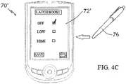
- a remote controller 70' is built into a personal digital assistant (PDA) loaded with and executing special-purpose code.
- PDA personal digital assistant
- An RF (or other wireless) communication card plugs into a port of the PDA and performs wireless communication functions under control of the PDA.
- the screen of the PDA acts as the display of the remote controller, and the manual input devices of the PDA - a keyboard or stylus-like pen 76 - is used to scroll and select the menu items.
- the stylus-like pen 76 may select a desired menu item by contacting the PDA screen and touching the menu item.
- the PDA can also provide electrical power to the RF communication card.
- the display screen 72' shows menu items corresponding to parameters to be performed by the door operator.
- Each menu item is represented on the display screen 72' by an icon or button.
- the user may use a stylus-like pen 76 to select the desired parameter to be adjusted by contacting the tip of the stylus pen against the display screen and pressing on the icon corresponding to the desired parameter. If the desired parameter is not listed, the user may press the "MENU ⁇ UP” or “MENU ⁇ DOWN" icon or button to view more options. A "BACK” or " " icon or button will return the user to the previous screen.
- the user may select, for example, the obstruction detection and delay sensitivity setting, as shown in Fig. 4B .
- the range of delay may be about 0 to about 5 seconds and adjustable in 1 second increments, as shown on display screen 72'.
- the user may again use stylus pen 76 to adjust the range of delay by touching the stylus pen against the display screen and sliding the toggle to the desired value, or alternatively, by pressing the "INCR ⁇ ” or " ⁇ DECR” icon or button to increase or decrease the value.
- the user may press inwardly on the "SAVE" icon or button using the stylus pen 76 to accept the values.
- the display screen 72' is capable of displaying information received or stored in the controller in various graphical representations, including alphanumeric characters, symbols, still images, videos, or animated graphics, such as 'check' boxes to adjust the "Latch Boost" feature. As shown in Fig. 4C , when contacting the tip of stylus pen 76 against the display screen touch interface in the desired 'check' box, individual pixels in the display illuminate to depict a 'check' mark graphic in the box next to the selected setting.
- the remote controller includes a port for downloading software, icon and/or other control, data for use by the remote controller in the course of operating its controlled systems.
- the data enables the remote controller, for example, to operate additional controlled systems, and to display new icons.
- the controller can be uploaded with an installation manual accessible to a technician for review.
- an installation manual for a door operator may be displayed for a technician while working with the unit in the field. This information may be desirable during installation, maintenance, or adjustment of gate operators.
- the controller may comprise a USB interface which may be used to upload or upgrade firmware for the controller.
- a serial port interface provides yet another connectivity option for the controller to hook up to other devices for the transfer of communication.
- a graphical user interface comprising a pixel display screen 72" capable of graphics and augmented with a planar touch select overlay is connected to the processor, e.g. a microprocessor or microcontroller, which controls movement of the door, wherein the GUI is coupled to the controller and the display screen with touch select overlay is the user input device.
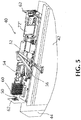
- the pixel display screen 72" is embedded in a door operator during production and hidden under a cover (not shown) which serves to surround and enclose the components of the door operator, as shown in Fig. 5 . In such a configuration, an installer or technician would need to remove the door operator's cover or housing to access the GUI.
- the pixel display screen may be positioned outside and adjacent to the door operator housing, such as on the same or an adjacent wall.
- the GUI may require the input of a preregistered security code by an authorized user.
- the planar touch interface may employ any type of touch array, such as a capacitive and/or resistive touch array.
- the GUI is pixel-controlled and control software can light (or dim) or change the color of individual pixels to display still images or alphanumeric characters or symbols, as well as display videos or animated graphics.
- the pixel display may be LCD, LED or any other technology.
- a pixel-controlled display is that the display is not limited to a linear menu structure, and instead may be configured as an applications ("apps") panel similar to a smartphone screen display. Activating an icon or button on a given screen using a user's fingers (or other touch-enabled interface) causes the display to change, such as going from a "start menu" to a subsequent screen to adjust a particular operating parameter setting.
- a memory module coupled to the processor stores code executed by the processor. Any information with respect to the door operator which is stored in the memory module, such as a preloaded installation instruction manual, an activation or setup wizard, or installation and/or troubleshooting videos, may be displayed on the GUI display screen 72" to assist the user. For example, if an installer or technician needs assistance in connecting a presence sensor while in the field, the technician may use the display screen's touch select interface to navigate the GUI to select a preloaded instructional video, which can then be viewed on the display.
- the memory module may include code comprising a self-diagnostic test of the door operator's operating parameters and internal circuitry, which can be performed by the processor.
- the processor sends a plurality of control signals to the door driver corresponding to designated parameters of door movement, the control signals are sent through the circuitry of the door operator, and the processor then receives data from the door driver responsive to the plurality of control signals.
- the system is capable of performing a self-test to diagnose and analyze whether the parameters of the door are performing correctly, displaying the results to the user on the GUI display, and providing instructions to the user as to suggested fixes, if any, for incorrectly performing parameters or circuitry.
- Suggested fixes may include jumping a connector or similar and completing the self-test to diagnose circuits that are not operating properly.
- the controller system allows for both self- and user-interactive analytics and diagnostics of the door operator.
- Fig. 6 provides an exemplary GUI which allows a user, installer, technician or the like, to set, adjust, troubleshoot, configure, or monitor settings within a door operator.
- the example is a flow of screens visible on the GUI to the user with soft icons or buttons to change settings for the inputs/outputs, input/output device numbers, functions and activations, with each selection dropping into a settings screen.
- the GUI screen 200 may be comprised of separate blocks of options with soft icons or buttons 210 and a scrolling text bar 220 in the middle.
- buttons 230 the user may select basic door operation parameters such as door motion settings, diagnostics, setup wizard or factory reset of all settings.
- the user may also select whether to use the control system of the present invention to set up any additional door operator input or output functions such as a wall switch, presence sensor, or any other input or output including but not limited to those described herein.
- the user selects on block 230 whether to adjust an input or output, e.g. selecting input 235, the user then selects on block 240 the particular input or output to change, that is, the input or output to which the device is connected, e.g., as device No. 1, 245.
- the user selects on block 250 the particular function for the input and, if the function is not shown, selects "More" 255, after which additional function blocks 260 are displayed.
- the user is then presented with the settings block 270 for that function, and the particular settings options are presented and the user may select and change those settings by subsequent setting screens.
- the GUI shows and identifies to the controller the selected door operator input or output and corresponding microprocessor input or output to the program module corresponding to the selected function to be performed.
- Fig. 7 provides a flowchart of an exemplary activation wizard displayed on the GUI display screen.
- the example is a progression of steps taken in either a new installation of a door operator or in changing one or more operating parameter settings in an existing setup.
- a user is greeted with a startup screen 300 allowing the user to select, for example, a "New Install” or to "Change Settings" using the GUI's planar touch interface.
- an icon or button 310 for example, for "New Install”
- the user is walked through a series of instructions 320 for set-up of the door operator, with each set of instructions or steps displayed on a subsequent screen.
- the GUI may display graphical representations or images to assist the user in performing the desired calibration, such as displaying an image of a dial to allow the user to adjust the opening or closing speed of the door driver.
- Other settings which may be set or adjusted using the GUI include but are not limited to obstruction detection and delay sensitivity, latch speed and position, backcheck speed and position, and latch boost.
- the GUI may also be used to instruct the user on how to install additional optional door operator input or output functions, such as a wall switch or presence sensor.
- the GUI is configured to display an instruction video or animated graphic 330 to assist the user in performing the instructed operation, such as wiring a wall switch or presence sensor to the appropriate terminals.
- the controller has many advantages, including providing installers and manufacturers with a means to set, adjust, command, test, troubleshoot, configure, upgrade, or monitor door operators.
- the controller has been shown and described in considerable detail with respect to only a few exemplary embodiments thereof, it should be understood by those skilled in the art that it is not intended to limit the invention to the embodiments since various modifications, omissions and additions may be made to the disclosed embodiments within the scope of the appended claims without materially departing from the novel teachings and advantages of the controller, particularly in light of the foregoing teachings. Accordingly, it is intended to cover all such modifications, omissions, additions, and equivalents as may be included within the scope of the following claims.
Landscapes
- Power-Operated Mechanisms For Wings (AREA)
- Control Of Indicators Other Than Cathode Ray Tubes (AREA)
Claims (15)
- Mécanisme d'actionnement de porte (40), comprenant :un logement de mécanisme d'actionnement de porte ;un moyen de commande de porte pour ouvrir et fermer une porte (42) ;un contrôleur qui inclut un microprocesseur, le microprocesseur étant connecté au moyen de commande de porte et le commandant ;une interface utilisateur graphique qui est intégrée à l'intérieur du mécanisme d'actionnement de porte (40) pendant la fabrication et qui est dissimulée au-dessous d'un capot, lequel capot sert à entourer et à renfermer les composants du mécanisme d'actionnement de porte, et à laquelle il est possible d'accéder en enlevant le capot ou au moins une partie du logement de mécanisme d'actionnement de porte, l'interface utilisateur graphique comprenant un écran d'affichage pixélisé (72") qui dispose d'une capacité graphique et qui est pourvu, en superposition, d'un moyen de sélection tactile plan qui constitue le dispositif d'entrée d'utilisateur et qui est couplé au microprocesseur de manière à permettre l'affichage des informations qui sont stockées dans le contrôleur et de manière à permettre que le microprocesseur reçoive des instructions qui sont sélectionnées à partir de l'écran d'affichage (72") par un utilisateur ;un module de mémoire qui est couplé au microprocesseur, le module de mémoire stockant un code qui est exécuté par le microprocesseur ;dans lequel le microprocesseur, sous la commande du code, affiche, à destination de l'utilisateur, divers éléments de menu sur l'écran d'affichage d'interface utilisateur graphique (72") et permet que l'utilisateur effectue une sélection au sein des éléments de menu en utilisant l'écran d'affichage (72") qui est muni d'une entrée de sélection tactile de telle sorte que le microprocesseur dérive un signal de commande ; etun circuit qui est configuré de manière à ce qu'il reçoive le signal de commande en provenance du microprocesseur et de manière à ce qu'il transfère le signal de commande au moyen de commande de porte.
- Mécanisme d'actionnement de porte selon la revendication 1, dans lequel l'écran d'affichage (72") qui est muni d'une entrée de sélection tactile comprend un réseau tactile résistif.
- Mécanisme d'actionnement de porte selon la revendication 1, dans lequel l'écran d'affichage (72") qui est muni d'une entrée de sélection tactile comprend un réseau tactile capacitif.
- Mécanisme d'actionnement de porte selon la revendication 1, dans lequel l'écran d'affichage d'interface utilisateur graphique (72") est commandé par pixels et est configuré de manière à ce qu'il éclaire des pixels individuels pour afficher l'information, l'affichage présentant une capacité de présentation d'une représentation qui est sélectionnée parmi un groupe qui comprend des caractères alphanumériques, des symboles, des images fixes, des vidéos et des graphiques animés.
- Mécanisme d'actionnement de porte selon la revendication 1, dans lequel chacun des éléments de menu correspond à au moins un paramètre de fonctionnement d'une pluralité de paramètres de fonctionnement à effectuer par le mécanisme d'actionnement de porte (40).
- Mécanisme d'actionnement de porte selon la revendication 1, dans lequel le module de mémoire inclut un code qui comprend un manuel d'instructions d'installation préchargé, un assistant d'activation, au moins une vidéo d'installation et au moins une vidéo de dépannage.
- Mécanisme d'actionnement de porte selon la revendication 1, comprenant en outre un moyen de stockage interne pour enregistrer et assurer le suivi des données qui sont envoyées sur le mécanisme d'actionnement de porte (40) ou qui sont reçues depuis celui-ci.
- Mécanisme d'actionnement de porte selon la revendication 1, dans lequel l'interface utilisateur graphique nécessite, de la part de l'utilisateur, l'entrée d'un code de sécurité préenregistré pour empêcher un accès non autorisé.
- Mécanisme d'actionnement de porte selon la revendication 1, comprenant en outre un capteur qui est connecté à une porte (42), dans lequel le contrôleur reçoit un signal de réponse en provenance de la porte (42) qui est porteur de données en provenance du capteur en réponse à l'application du signal de commande sur le mécanisme d'actionnement de porte (40).
- Mécanisme d'actionnement de porte selon la revendication 9, dans lequel les données comprennent une position de porte.
- Mécanisme d'actionnement de porte selon la revendication 1, dans lequel le module de mémoire inclut un code qui comprend un test de diagnostic, et dans lequel le microprocesseur dispose de la capacité de diagnostiquer et d'analyser un fonctionnement de la porte (42).
- Procédé de réglage de paramètres à l'intérieur d'un mécanisme d'actionnement de porte (40), comprenant les étapes constituées par :la fourniture d'un mécanisme d'actionnement de porte (40) selon l'une des revendications qui précèdent ;l'affichage à destination de l'utilisateur, sur l'écran d'affichage (72"), d'éléments de menu qui correspondent à des paramètres à effectuer par le mécanisme d'actionnement de porte (40) ;la sélection, au sein des éléments de menu, par effleurement tactile d'un élément de menu sur l'écran d'affichage (72") de telle sorte que le microprocesseur dérive un signal de commande ; etl'envoi du signal de commande au moyen de commande de porte afin de commander un paramètre de mouvement de porte.
- Procédé selon la revendication 12, comprenant en outre un capteur qui est connecté au mécanisme d'actionnement de porte (40), dans lequel un signal de réponse en provenance du mécanisme d'actionnement de porte (40) comprend un signal en provenance du capteur.
- Procédé selon la revendication 12, comprenant en outre l'étape de surveillance d'une porte (42) qui est connectée au mécanisme d'actionnement de porte (40).
- Procédé selon la revendication 12, dans lequel le microprocesseur diagnostique et analyse un fonctionnement d'une porte (42) qui est connectée au mécanisme d'actionnement de porte (40).
Applications Claiming Priority (2)
| Application Number | Priority Date | Filing Date | Title |
|---|---|---|---|
| US201461993349P | 2014-05-15 | 2014-05-15 | |
| PCT/US2015/030494 WO2015175614A1 (fr) | 2014-05-15 | 2015-05-13 | Dispositif de commande pour un actionneur de porte |
Publications (3)
| Publication Number | Publication Date |
|---|---|
| EP3143231A1 EP3143231A1 (fr) | 2017-03-22 |
| EP3143231A4 EP3143231A4 (fr) | 2017-05-03 |
| EP3143231B1 true EP3143231B1 (fr) | 2020-03-04 |
Family
ID=54480585
Family Applications (1)
| Application Number | Title | Priority Date | Filing Date |
|---|---|---|---|
| EP15792031.5A Active EP3143231B1 (fr) | 2014-05-15 | 2015-05-13 | Dispositif de commande pour un actionneur de porte |
Country Status (6)
| Country | Link |
|---|---|
| EP (1) | EP3143231B1 (fr) |
| CN (1) | CN106460442B (fr) |
| CA (1) | CA2948358C (fr) |
| MX (1) | MX367412B (fr) |
| TW (1) | TW201600703A (fr) |
| WO (1) | WO2015175614A1 (fr) |
Cited By (1)
| Publication number | Priority date | Publication date | Assignee | Title |
|---|---|---|---|---|
| EP4105426A1 (fr) | 2021-06-18 | 2022-12-21 | dormakaba Deutschland GmbH | Actionneur de porte permettant d'actionner un élément de battant d'une installation de porte |
Families Citing this family (13)
| Publication number | Priority date | Publication date | Assignee | Title |
|---|---|---|---|---|
| US11162292B2 (en) | 2016-06-22 | 2021-11-02 | Assa Abloy Entrance Systems Ab | Door operator and method for set-up of a door operator |
| DE102016221339B4 (de) * | 2016-10-28 | 2026-02-19 | Geze Gmbh | Überwachungssystem eines türschliessers |
| US11692385B2 (en) * | 2016-10-28 | 2023-07-04 | Assa Abloy Entrance Systems Ab | System and method for configuration of door entrance systems |
| CN107180471A (zh) * | 2017-07-06 | 2017-09-19 | 深圳市嘉昱机电有限公司 | 基于rs485通信协议的闸机控制装置和系统 |
| KR20240132107A (ko) * | 2017-08-04 | 2024-09-02 | 아사 알보이 엔트란스 시스템스 에이비 | 도어 오퍼레이터 |
| DE102019209521B4 (de) * | 2019-06-28 | 2021-04-15 | Geze Gmbh | Benutzerschnittstelleneinheit |
| US11118392B2 (en) | 2019-07-15 | 2021-09-14 | Vengeance Creek, LLC | Swinging door operator |
| EP4031737A1 (fr) | 2019-09-16 | 2022-07-27 | ASSA ABLOY Entrance Systems AB | Système de test pour système d'entrée basé sur une porte battante |
| EP4031738A1 (fr) * | 2019-09-16 | 2022-07-27 | ASSA ABLOY Entrance Systems AB | Système d'entrée et procédé de fonctionnement d'un tel système d'entrée |
| KR20220081175A (ko) * | 2020-12-08 | 2022-06-15 | 에스케이하이닉스 주식회사 | 메모리 장치 |
| CN113309435B (zh) * | 2021-05-27 | 2022-12-13 | 广东路遥医特工程有限公司 | 一种重型可调安装位置的90°开门机 |
| TWI779908B (zh) * | 2021-10-27 | 2022-10-01 | 一德金屬工業股份有限公司 | 控制面板外露的門弓器 |
| CN114458122A (zh) * | 2022-02-08 | 2022-05-10 | 浙江极氪智能科技有限公司 | 一种车辆后备箱的箱门的控制方法及其系统 |
Family Cites Families (11)
| Publication number | Priority date | Publication date | Assignee | Title |
|---|---|---|---|---|
| US7207142B2 (en) * | 2002-12-04 | 2007-04-24 | Wayne-Dalton Corp. | System and related methods for signaling the position of a movable barrier and securing its position |
| US8126676B2 (en) * | 2008-02-22 | 2012-02-28 | The Boeing Company | Door monitoring system |
| CN201460566U (zh) * | 2008-07-09 | 2010-05-12 | 张增辉 | 一种全自动车窗升降智能控制器 |
| KR20110006117A (ko) * | 2009-07-13 | 2011-01-20 | 이요한 | 터치패드를 이용한 패스워드 입력장치 및 입력방법 |
| EP2499320A1 (fr) * | 2009-11-13 | 2012-09-19 | Dorma GmbH + Co. KG | Revêtement pour un actionneur de porte |
| CN101748952A (zh) * | 2009-12-16 | 2010-06-23 | 贵州大学 | 汽车can总线电动车窗控制系统 |
| US20120272576A1 (en) * | 2010-03-20 | 2012-11-01 | Van Tassell Iii Ronald E | System and device for opening and closing sliding doors |
| FR2976612B1 (fr) * | 2011-06-16 | 2014-05-16 | Somfy Sas | Systeme d'ouverture et de fermeture d'ouvrants, et installation d'isolation thermique et de protection solaire equipee d'un tel systeme |
| DE102011082859A1 (de) * | 2011-09-16 | 2013-03-21 | BSH Bosch und Siemens Hausgeräte GmbH | Haushaltsgerät |
| US9243448B2 (en) * | 2012-01-25 | 2016-01-26 | Cornell Ironworks Enterprises | Door control systems |
| CN202467460U (zh) * | 2012-02-27 | 2012-10-03 | 宁波市鄞州美必盛自动门厂 | 带触摸屏的自动门控制系统 |
-
2015
- 2015-05-13 EP EP15792031.5A patent/EP3143231B1/fr active Active
- 2015-05-13 MX MX2016014873A patent/MX367412B/es active IP Right Grant
- 2015-05-13 CA CA2948358A patent/CA2948358C/fr active Active
- 2015-05-13 WO PCT/US2015/030494 patent/WO2015175614A1/fr not_active Ceased
- 2015-05-13 CN CN201580026735.4A patent/CN106460442B/zh not_active Expired - Fee Related
- 2015-05-14 TW TW104115339A patent/TW201600703A/zh unknown
Non-Patent Citations (1)
| Title |
|---|
| None * |
Cited By (1)
| Publication number | Priority date | Publication date | Assignee | Title |
|---|---|---|---|---|
| EP4105426A1 (fr) | 2021-06-18 | 2022-12-21 | dormakaba Deutschland GmbH | Actionneur de porte permettant d'actionner un élément de battant d'une installation de porte |
Also Published As
| Publication number | Publication date |
|---|---|
| MX2016014873A (es) | 2017-05-30 |
| TW201600703A (zh) | 2016-01-01 |
| CN106460442B (zh) | 2018-04-13 |
| MX367412B (es) | 2019-08-21 |
| CA2948358C (fr) | 2021-04-06 |
| CN106460442A (zh) | 2017-02-22 |
| WO2015175614A1 (fr) | 2015-11-19 |
| EP3143231A1 (fr) | 2017-03-22 |
| CA2948358A1 (fr) | 2015-11-19 |
| EP3143231A4 (fr) | 2017-05-03 |
Similar Documents
| Publication | Publication Date | Title |
|---|---|---|
| US9514583B2 (en) | Controller for a door operator | |
| EP3143231B1 (fr) | Dispositif de commande pour un actionneur de porte | |
| US20140259927A1 (en) | Controller for a door operator | |
| US11756410B2 (en) | Door system with active monitoring | |
| US11847864B2 (en) | Door system with authentication and activation | |
| US12031373B2 (en) | Door system with improved installation, set-up, and cloning | |
| US8724331B2 (en) | Intelligent wall-mounted switch module | |
| JP6424016B2 (ja) | 動作モード切替装置 | |
| US20200378172A1 (en) | An entrance system having one or more movable door members and an intelligent glass panel | |
| PL226957B1 (pl) | System isposób zdalnego sterowania urzadzeniami budynku, zwłaszcza zdalnego sterowania napedu automatycznego bramy zamykajacej posesje, wzglednie budynek, badz innych zdalnie sterowanych urzadzen wyposazenia budynku | |
| US8972030B2 (en) | Control device comprising an interface capable of proposing the next control command to be transmitted to a home-automation appliance | |
| CN112282564B (zh) | 一种基于客户端的电动门远程控制系统 | |
| CN209763448U (zh) | 一种空调面板及空调器 | |
| KR100378130B1 (ko) | 터치스크린형 엘리베이터 시스템 | |
| JP2018167924A (ja) | エレベータのドア調整システム、携帯端末機器 | |
| US20230259376A1 (en) | Gate Operator with Context Sensitive QR Code | |
| CN223881021U (zh) | 一种推拉门窗及其系统 | |
| CN103329072B (zh) | 用于控制具有可调板的电机驱动的移动遮蔽物的设备和方法 | |
| EP3938607A1 (fr) | Système de porte à installation, mise en place et clonage améliorés | |
| JP2022056244A (ja) | 遠隔操作システム、遠隔操作装置、及び遠隔操作方法 | |
| CN110491322A (zh) | 荧幕显示驱动电路以及控制方法 | |
| JP2017014796A (ja) | シャッター側制御装置、及びシャッターの制御システム |
Legal Events
| Date | Code | Title | Description |
|---|---|---|---|
| STAA | Information on the status of an ep patent application or granted ep patent |
Free format text: STATUS: THE INTERNATIONAL PUBLICATION HAS BEEN MADE |
|
| PUAI | Public reference made under article 153(3) epc to a published international application that has entered the european phase |
Free format text: ORIGINAL CODE: 0009012 |
|
| STAA | Information on the status of an ep patent application or granted ep patent |
Free format text: STATUS: REQUEST FOR EXAMINATION WAS MADE |
|
| 17P | Request for examination filed |
Effective date: 20161129 |
|
| AK | Designated contracting states |
Kind code of ref document: A1 Designated state(s): AL AT BE BG CH CY CZ DE DK EE ES FI FR GB GR HR HU IE IS IT LI LT LU LV MC MK MT NL NO PL PT RO RS SE SI SK SM TR |
|
| AX | Request for extension of the european patent |
Extension state: BA ME |
|
| A4 | Supplementary search report drawn up and despatched |
Effective date: 20170330 |
|
| RIC1 | Information provided on ipc code assigned before grant |
Ipc: E05F 15/70 20150101AFI20170325BHEP Ipc: G08B 13/08 20060101ALI20170325BHEP |
|
| DAV | Request for validation of the european patent (deleted) | ||
| DAX | Request for extension of the european patent (deleted) | ||
| GRAP | Despatch of communication of intention to grant a patent |
Free format text: ORIGINAL CODE: EPIDOSNIGR1 |
|
| STAA | Information on the status of an ep patent application or granted ep patent |
Free format text: STATUS: GRANT OF PATENT IS INTENDED |
|
| INTG | Intention to grant announced |
Effective date: 20190722 |
|
| GRAJ | Information related to disapproval of communication of intention to grant by the applicant or resumption of examination proceedings by the epo deleted |
Free format text: ORIGINAL CODE: EPIDOSDIGR1 |
|
| GRAL | Information related to payment of fee for publishing/printing deleted |
Free format text: ORIGINAL CODE: EPIDOSDIGR3 |
|
| STAA | Information on the status of an ep patent application or granted ep patent |
Free format text: STATUS: REQUEST FOR EXAMINATION WAS MADE |
|
| GRAS | Grant fee paid |
Free format text: ORIGINAL CODE: EPIDOSNIGR3 |
|
| GRAP | Despatch of communication of intention to grant a patent |
Free format text: ORIGINAL CODE: EPIDOSNIGR1 |
|
| STAA | Information on the status of an ep patent application or granted ep patent |
Free format text: STATUS: GRANT OF PATENT IS INTENDED |
|
| INTG | Intention to grant announced |
Effective date: 20191030 |
|
| GRAA | (expected) grant |
Free format text: ORIGINAL CODE: 0009210 |
|
| STAA | Information on the status of an ep patent application or granted ep patent |
Free format text: STATUS: THE PATENT HAS BEEN GRANTED |
|
| AK | Designated contracting states |
Kind code of ref document: B1 Designated state(s): AL AT BE BG CH CY CZ DE DK EE ES FI FR GB GR HR HU IE IS IT LI LT LU LV MC MK MT NL NO PL PT RO RS SE SI SK SM TR |
|
| REG | Reference to a national code |
Ref country code: GB Ref legal event code: FG4D |
|
| REG | Reference to a national code |
Ref country code: CH Ref legal event code: EP |
|
| REG | Reference to a national code |
Ref country code: AT Ref legal event code: REF Ref document number: 1240544 Country of ref document: AT Kind code of ref document: T Effective date: 20200315 |
|
| REG | Reference to a national code |
Ref country code: DE Ref legal event code: R096 Ref document number: 602015048246 Country of ref document: DE |
|
| REG | Reference to a national code |
Ref country code: IE Ref legal event code: FG4D |
|
| PG25 | Lapsed in a contracting state [announced via postgrant information from national office to epo] |
Ref country code: RS Free format text: LAPSE BECAUSE OF FAILURE TO SUBMIT A TRANSLATION OF THE DESCRIPTION OR TO PAY THE FEE WITHIN THE PRESCRIBED TIME-LIMIT Effective date: 20200304 Ref country code: FI Free format text: LAPSE BECAUSE OF FAILURE TO SUBMIT A TRANSLATION OF THE DESCRIPTION OR TO PAY THE FEE WITHIN THE PRESCRIBED TIME-LIMIT Effective date: 20200304 Ref country code: NO Free format text: LAPSE BECAUSE OF FAILURE TO SUBMIT A TRANSLATION OF THE DESCRIPTION OR TO PAY THE FEE WITHIN THE PRESCRIBED TIME-LIMIT Effective date: 20200604 |
|
| REG | Reference to a national code |
Ref country code: NL Ref legal event code: MP Effective date: 20200304 |
|
| PG25 | Lapsed in a contracting state [announced via postgrant information from national office to epo] |
Ref country code: HR Free format text: LAPSE BECAUSE OF FAILURE TO SUBMIT A TRANSLATION OF THE DESCRIPTION OR TO PAY THE FEE WITHIN THE PRESCRIBED TIME-LIMIT Effective date: 20200304 Ref country code: BG Free format text: LAPSE BECAUSE OF FAILURE TO SUBMIT A TRANSLATION OF THE DESCRIPTION OR TO PAY THE FEE WITHIN THE PRESCRIBED TIME-LIMIT Effective date: 20200604 Ref country code: LV Free format text: LAPSE BECAUSE OF FAILURE TO SUBMIT A TRANSLATION OF THE DESCRIPTION OR TO PAY THE FEE WITHIN THE PRESCRIBED TIME-LIMIT Effective date: 20200304 Ref country code: SE Free format text: LAPSE BECAUSE OF FAILURE TO SUBMIT A TRANSLATION OF THE DESCRIPTION OR TO PAY THE FEE WITHIN THE PRESCRIBED TIME-LIMIT Effective date: 20200304 Ref country code: GR Free format text: LAPSE BECAUSE OF FAILURE TO SUBMIT A TRANSLATION OF THE DESCRIPTION OR TO PAY THE FEE WITHIN THE PRESCRIBED TIME-LIMIT Effective date: 20200605 |
|
| REG | Reference to a national code |
Ref country code: LT Ref legal event code: MG4D |
|
| PG25 | Lapsed in a contracting state [announced via postgrant information from national office to epo] |
Ref country code: NL Free format text: LAPSE BECAUSE OF FAILURE TO SUBMIT A TRANSLATION OF THE DESCRIPTION OR TO PAY THE FEE WITHIN THE PRESCRIBED TIME-LIMIT Effective date: 20200304 |
|
| PG25 | Lapsed in a contracting state [announced via postgrant information from national office to epo] |
Ref country code: IS Free format text: LAPSE BECAUSE OF FAILURE TO SUBMIT A TRANSLATION OF THE DESCRIPTION OR TO PAY THE FEE WITHIN THE PRESCRIBED TIME-LIMIT Effective date: 20200704 Ref country code: RO Free format text: LAPSE BECAUSE OF FAILURE TO SUBMIT A TRANSLATION OF THE DESCRIPTION OR TO PAY THE FEE WITHIN THE PRESCRIBED TIME-LIMIT Effective date: 20200304 Ref country code: CZ Free format text: LAPSE BECAUSE OF FAILURE TO SUBMIT A TRANSLATION OF THE DESCRIPTION OR TO PAY THE FEE WITHIN THE PRESCRIBED TIME-LIMIT Effective date: 20200304 Ref country code: SK Free format text: LAPSE BECAUSE OF FAILURE TO SUBMIT A TRANSLATION OF THE DESCRIPTION OR TO PAY THE FEE WITHIN THE PRESCRIBED TIME-LIMIT Effective date: 20200304 Ref country code: PT Free format text: LAPSE BECAUSE OF FAILURE TO SUBMIT A TRANSLATION OF THE DESCRIPTION OR TO PAY THE FEE WITHIN THE PRESCRIBED TIME-LIMIT Effective date: 20200729 Ref country code: SM Free format text: LAPSE BECAUSE OF FAILURE TO SUBMIT A TRANSLATION OF THE DESCRIPTION OR TO PAY THE FEE WITHIN THE PRESCRIBED TIME-LIMIT Effective date: 20200304 Ref country code: EE Free format text: LAPSE BECAUSE OF FAILURE TO SUBMIT A TRANSLATION OF THE DESCRIPTION OR TO PAY THE FEE WITHIN THE PRESCRIBED TIME-LIMIT Effective date: 20200304 Ref country code: LT Free format text: LAPSE BECAUSE OF FAILURE TO SUBMIT A TRANSLATION OF THE DESCRIPTION OR TO PAY THE FEE WITHIN THE PRESCRIBED TIME-LIMIT Effective date: 20200304 Ref country code: ES Free format text: LAPSE BECAUSE OF FAILURE TO SUBMIT A TRANSLATION OF THE DESCRIPTION OR TO PAY THE FEE WITHIN THE PRESCRIBED TIME-LIMIT Effective date: 20200304 |
|
| REG | Reference to a national code |
Ref country code: AT Ref legal event code: MK05 Ref document number: 1240544 Country of ref document: AT Kind code of ref document: T Effective date: 20200304 |
|
| REG | Reference to a national code |
Ref country code: DE Ref legal event code: R097 Ref document number: 602015048246 Country of ref document: DE |
|
| PLBE | No opposition filed within time limit |
Free format text: ORIGINAL CODE: 0009261 |
|
| STAA | Information on the status of an ep patent application or granted ep patent |
Free format text: STATUS: NO OPPOSITION FILED WITHIN TIME LIMIT |
|
| PG25 | Lapsed in a contracting state [announced via postgrant information from national office to epo] |
Ref country code: AT Free format text: LAPSE BECAUSE OF FAILURE TO SUBMIT A TRANSLATION OF THE DESCRIPTION OR TO PAY THE FEE WITHIN THE PRESCRIBED TIME-LIMIT Effective date: 20200304 Ref country code: DK Free format text: LAPSE BECAUSE OF FAILURE TO SUBMIT A TRANSLATION OF THE DESCRIPTION OR TO PAY THE FEE WITHIN THE PRESCRIBED TIME-LIMIT Effective date: 20200304 Ref country code: CH Free format text: LAPSE BECAUSE OF NON-PAYMENT OF DUE FEES Effective date: 20200531 Ref country code: LI Free format text: LAPSE BECAUSE OF NON-PAYMENT OF DUE FEES Effective date: 20200531 Ref country code: IT Free format text: LAPSE BECAUSE OF FAILURE TO SUBMIT A TRANSLATION OF THE DESCRIPTION OR TO PAY THE FEE WITHIN THE PRESCRIBED TIME-LIMIT Effective date: 20200304 Ref country code: MC Free format text: LAPSE BECAUSE OF FAILURE TO SUBMIT A TRANSLATION OF THE DESCRIPTION OR TO PAY THE FEE WITHIN THE PRESCRIBED TIME-LIMIT Effective date: 20200304 |
|
| 26N | No opposition filed |
Effective date: 20201207 |
|
| PG25 | Lapsed in a contracting state [announced via postgrant information from national office to epo] |
Ref country code: PL Free format text: LAPSE BECAUSE OF FAILURE TO SUBMIT A TRANSLATION OF THE DESCRIPTION OR TO PAY THE FEE WITHIN THE PRESCRIBED TIME-LIMIT Effective date: 20200304 Ref country code: SI Free format text: LAPSE BECAUSE OF FAILURE TO SUBMIT A TRANSLATION OF THE DESCRIPTION OR TO PAY THE FEE WITHIN THE PRESCRIBED TIME-LIMIT Effective date: 20200304 |
|
| REG | Reference to a national code |
Ref country code: BE Ref legal event code: MM Effective date: 20200531 |
|
| PG25 | Lapsed in a contracting state [announced via postgrant information from national office to epo] |
Ref country code: LU Free format text: LAPSE BECAUSE OF NON-PAYMENT OF DUE FEES Effective date: 20200513 |
|
| PG25 | Lapsed in a contracting state [announced via postgrant information from national office to epo] |
Ref country code: FR Free format text: LAPSE BECAUSE OF NON-PAYMENT OF DUE FEES Effective date: 20200531 Ref country code: IE Free format text: LAPSE BECAUSE OF NON-PAYMENT OF DUE FEES Effective date: 20200513 |
|
| PG25 | Lapsed in a contracting state [announced via postgrant information from national office to epo] |
Ref country code: BE Free format text: LAPSE BECAUSE OF NON-PAYMENT OF DUE FEES Effective date: 20200531 |
|
| PG25 | Lapsed in a contracting state [announced via postgrant information from national office to epo] |
Ref country code: TR Free format text: LAPSE BECAUSE OF FAILURE TO SUBMIT A TRANSLATION OF THE DESCRIPTION OR TO PAY THE FEE WITHIN THE PRESCRIBED TIME-LIMIT Effective date: 20200304 Ref country code: MT Free format text: LAPSE BECAUSE OF FAILURE TO SUBMIT A TRANSLATION OF THE DESCRIPTION OR TO PAY THE FEE WITHIN THE PRESCRIBED TIME-LIMIT Effective date: 20200304 Ref country code: CY Free format text: LAPSE BECAUSE OF FAILURE TO SUBMIT A TRANSLATION OF THE DESCRIPTION OR TO PAY THE FEE WITHIN THE PRESCRIBED TIME-LIMIT Effective date: 20200304 |
|
| PG25 | Lapsed in a contracting state [announced via postgrant information from national office to epo] |
Ref country code: MK Free format text: LAPSE BECAUSE OF FAILURE TO SUBMIT A TRANSLATION OF THE DESCRIPTION OR TO PAY THE FEE WITHIN THE PRESCRIBED TIME-LIMIT Effective date: 20200304 Ref country code: AL Free format text: LAPSE BECAUSE OF FAILURE TO SUBMIT A TRANSLATION OF THE DESCRIPTION OR TO PAY THE FEE WITHIN THE PRESCRIBED TIME-LIMIT Effective date: 20200304 |
|
| P01 | Opt-out of the competence of the unified patent court (upc) registered |
Effective date: 20230517 |
|
| PGFP | Annual fee paid to national office [announced via postgrant information from national office to epo] |
Ref country code: DE Payment date: 20250408 Year of fee payment: 11 |
|
| PGFP | Annual fee paid to national office [announced via postgrant information from national office to epo] |
Ref country code: GB Payment date: 20250410 Year of fee payment: 11 |