EP3143247B1 - Systèmes et procédés de détermination d'un paramètre rhéologique - Google Patents
Systèmes et procédés de détermination d'un paramètre rhéologique Download PDFInfo
- Publication number
- EP3143247B1 EP3143247B1 EP15792712.0A EP15792712A EP3143247B1 EP 3143247 B1 EP3143247 B1 EP 3143247B1 EP 15792712 A EP15792712 A EP 15792712A EP 3143247 B1 EP3143247 B1 EP 3143247B1
- Authority
- EP
- European Patent Office
- Prior art keywords
- fluid
- flow
- processing device
- wellbore
- differential pressure
- Prior art date
- Legal status (The legal status is an assumption and is not a legal conclusion. Google has not performed a legal analysis and makes no representation as to the accuracy of the status listed.)
- Active
Links
Images






Classifications
-
- E—FIXED CONSTRUCTIONS
- E21—EARTH OR ROCK DRILLING; MINING
- E21B—EARTH OR ROCK DRILLING; OBTAINING OIL, GAS, WATER, SOLUBLE OR MELTABLE MATERIALS OR A SLURRY OF MINERALS FROM WELLS
- E21B47/00—Survey of boreholes or wells
- E21B47/10—Locating fluid leaks, intrusions or movements
-
- E—FIXED CONSTRUCTIONS
- E21—EARTH OR ROCK DRILLING; MINING
- E21B—EARTH OR ROCK DRILLING; OBTAINING OIL, GAS, WATER, SOLUBLE OR MELTABLE MATERIALS OR A SLURRY OF MINERALS FROM WELLS
- E21B47/00—Survey of boreholes or wells
- E21B47/06—Measuring temperature or pressure
-
- E—FIXED CONSTRUCTIONS
- E21—EARTH OR ROCK DRILLING; MINING
- E21B—EARTH OR ROCK DRILLING; OBTAINING OIL, GAS, WATER, SOLUBLE OR MELTABLE MATERIALS OR A SLURRY OF MINERALS FROM WELLS
- E21B49/00—Testing the nature of borehole walls; Formation testing; Methods or apparatus for obtaining samples of soil or well fluids, specially adapted to earth drilling or wells
- E21B49/08—Obtaining fluid samples or testing fluids, in boreholes or wells
- E21B49/087—Well testing, e.g. testing for reservoir productivity or formation parameters
- E21B49/0875—Well testing, e.g. testing for reservoir productivity or formation parameters determining specific fluid parameters
Definitions
- the present disclosure relates to systems and methods for determining a rheological parameter of a fluid within a wellbore.
- Measuring rheological properties of fluids for optimum maintenance and optimum wellbore hydraulic management is one of the most important tasks during drilling and other downhole operations. This task is conducted by viscosity measurements that express a relationship between shear stress and shear rate. In drilling practice, such measurements are carried out at the rig site using test protocols and equipment as standardized by the American Petroleum Institute (API), such as API standards 13-B1, 13-B2, 13C and 13D.
- API American Petroleum Institute
- the rheology determination is carried out with simplistic equipment at atmospheric pressure and standardized temperatures at the surface.
- the obtained rheology measurements therefore do not properly reflect the actual well conditions experienced by the fluid within the wellbore.
- measurements are not performed in real time and are conducted depending on the availability of the mud engineer. Inaccurate measurements of the rheological properties can possibly lead to miscalculated predictions of annular frictional pressure drops and Equivalent Circulating Density (ECD).
- ECD Equivalent Circulating Density
- US 2013/048380 A1 discloses a method for determining one or more interval densities in a subterranean wellbore.
- US 2011/0042076 A1 discloses a method for determining fluid control events in a borehole by controlling formation pressure during drilling of the borehole.
- a system and method for visualization and characterization of a flowing fluid by using one or more transducers are disclosed in US 2013/0345994 A1 .
- US 2013/0025359 Al is directed to a viscometer for downhole use and discloses a method and apparatus for measuring viscosity of a fluid in a borehole by making differential pressure measurements when pumping a downhole fluid through a tube and estimating a viscosity of the fluid based on the differential pressure measurements.
- US 4 726 219 A discloses a method and system for determining fluid pressures in wellbores and tubular conduits by conducting flow of a fluid at the same Reynolds number through a pipe viscometer having the same roughness characteristics as that of the conduit or wellbore, measuring the friction pressure loss and the viscosity to determine the Fanning friction factor and to finally calculate an expected pressure drop in the conduit or wellbore.
- the method comprises receiving, using a processing device, a plurality of measured flow rates and a plurality of differential pressure measurements corresponding to the plurality of measured flow rates of the fluid within a flow region of the wellbore, wherein the plurality of differential pressure measurements are obtained at downhole conditions of the wellbore; storing, using the processing device, the plurality of measured flow rates and the plurality of differential pressure measurements; generating, using the processing device, a flow curve based on the plurality of differential pressure measurements and the plurality of measured flow rates; determining, using the processing device, a flow behavior index for the fluid from the flow curve; and determining, using the processing device, the rheological parameter of the fluid using the flow curve and a rheological model; wherein the flow region comprises an area inside a conduit situated within the wellbore.
- the differential pressure measurements of the fluid are obtained at downhole conditions of the wellbore.
- receiving a plurality of differential pressure measurements corresponding to the plurality of measured flow rates of the fluid flowing within a flow region of the wellbore comprises receiving, using a processing device, pressure measurements of the fluid from a plurality of pressure sensors; and calculating, using the processing device, the plurality of differential pressure measurements of the fluid from the pressure measurements.
- the generating and determining steps comprise generating, using the processing device, a pressure curve based on the plurality of differential pressure measurements, and determining, using the processing device, the rheological parameter of the fluid using the pressure curve.
- the plurality of differential pressure measurements correspond to a plurality of measured flow rates of the fluid flowing within a flow region of the wellbore and said receiving and storing steps comprise receiving and storing, using the processing device, the differential pressure measurements for the flow rates of the fluid.
- the flow rates can include at least three or at least five different flow rates.
- the method comprises generating, using the processing device, a flow curve based on the differential pressure measurements and the plurality of flow rates; determining, using the processing device, a flow behavior index for the fluid from the flow curve; and determining, using the processing device, the rheological parameter of the fluid using the flow curve and a rheological model.
- the method further comprises correcting, using the processing device, the differential pressure measurements of the fluid for eccentricity between a conduit and the wellbore.
- the differential pressure measurements of the fluid can be corrected for the eccentricity between the conduit and the wellbore using an equivalent pipe model, a correlation-based model, or a combination thereof.
- the flow region can include an area inside a conduit situated within the wellbore.
- the flow region can include an annulus between the conduit and the wellbore.
- the fluid is a drilling fluid.
- the flow curve can be used to produce a logarithmic plot of shear stress at a wall of the conduit versus nominal Newtonian shear rate.
- the slope of the logarithmic plot can include a generalized flow behavior index and the intercept of the logarithmic plot can include a generalized consistency index.
- the rheological model can include a model that can relate shear stress and shear rate.
- the rheological model comprises the Yield Power Law model.
- the rheological parameter is determined based on a shear stress and a shear rate of the fluid.
- the method further comprises receiving, using the processing device, times corresponding to each of the differential pressure measurements of the fluid.
- the method can further comprise generating, using the processing device, a pressure curve over time based on the differential pressure measurements of the fluid.
- the method can further comprise estimating, using the processing device, the gel strength of the fluid using the pressure curve over time.
- the system comprises a conduit arranged in a wellbore.
- the system further comprises a flow meter configured to measure a flow rate of the fluid flowing within the conduit and a plurality of pressure sensors configured to measure pressure of the fluid flowing within the wellbore at downhole conditions of the wellbore.
- the system further comprises a processing device configured to receive a plurality of flow rates of the fluid from the flow meter; to receive a plurality of differential pressure measurements of the fluid from the plurality of pressure sensors, wherein the plurality of differential pressure measurements correspond to the plurality of flow rates; to store the plurality of flow rates and the plurality of differential pressure measurements corresponding to the plurality of flow rates, to generate a flow curve based on plurality of flow rates and the plurality of differential pressure measurements, and to determine the rheological parameter of the fluid using the flow curve and a rheological model.
- a processing device configured to receive a plurality of flow rates of the fluid from the flow meter; to receive a plurality of differential pressure measurements of the fluid from the plurality of pressure sensors, wherein the plurality of differential pressure measurements correspond to the plurality of flow rates; to store the plurality of flow rates and the plurality of differential pressure measurements corresponding to the plurality of flow rates, to generate a flow curve based on plurality of flow rates and the plurality of differential pressure measurements, and
- the system comprises a flow meter configured to measure flow rate of the fluid flowing within the wellbore
- the processing device can be further configured to receive a plurality of flow rates of the fluid from the flow meter, receive differential pressure measurements of the fluid from the pressure sensors for the plurality of flow rates of the fluid, store the differential pressure measurements for the plurality of flow rates of the fluid, generate a flow curve based on the differential pressure measurements for the plurality of flow rates of the fluid, and determine the rheological parameter of the fluid using the flow curve and a rheological model.
- the plurality of pressure sensors along the conduit are configured to measure the pressure of the fluid flowing within an annulus of the wellbore, the annulus of the wellbore being a region between the conduit and the wellbore.
- the system can include the other features described herein with respect to the disclosed method.
- the rheological parameter can be determined from a shear stress and a shear rate of the fluid.
- the rheological parameter can be determined from a relationship between the shear stress and shear rate of the fluid.
- the fluid can comprise any fluid used in a wellbore application such as, for example, a drilling fluid, a spacer fluid, a cementitious fluid, a packer fluid, a completion fluid, a completion brine fluid, a drill-in fluid, or a combination thereof.
- the method comprises receiving, using a processing device, a plurality of differential pressure measurements of the fluid flowing within a flow region of the wellbore.
- the plurality of differential pressure measurements can correspond to a plurality of measured flow rates of the fluid flowing within a flow region of the wellbore.
- receiving the plurality of flow rates of the fluid flowing within a flow region of the wellbore comprises receiving, using a processing device, a plurality of flow rates of the fluid from a flow meter.
- the plurality of flow rates can, for example, comprise a plurality of flow rates obtained from substantially steady state flow conditions.
- the plurality of flow rates includes at least 3 (e.g., at least 4, at least 5, at least 10, or at least 50) different flow rates.
- the plurality of flow rates can be derived from a continuous pump ramp-up curve.
- the plurality of flow rates can be derived from steady state conditions.
- the respective differential pressure measurements for the plurality of flow rates of the fluid are obtained at downhole conditions (e.g., downhole temperatures and pressures) of the wellbore.
- the wellbore can be a vertical wellbore, a deviated wellbore, a horizontal wellbore, or a combination thereof.
- the differential pressure measurement for flow rate of the fluid can, for example, be in a laminar flow regime, a transitional flow regime, a turbulent flow regime, or combinations thereof. In some examples, the differential pressure measurements for flow rate of the fluid are in a laminar flow regime.
- the flow region of the wellbore can comprise any region where the fluid can flow and pressure can be measured within the wellbore.
- the flow region comprises an area inside a conduit (e.g., a drill pipe, a wired drill pipe, a tube, or a casing) situated within the wellbore.
- the flow region comprises an annulus.
- the annulus for example, can comprise a region between the conduit and the wellbore, a region between a bottom-hole assembly and the wellbore, or a combination thereof.
- receiving the differential pressure measurements of the fluid flowing within a flow region of the wellbore comprises receiving, using a processing device, pressure measurements of the fluid from a plurality of pressure sensors. In some examples, receiving the differential pressure measurements of the fluid flowing within a flow region of the wellbore further comprises calculating, using the processing device, the differential pressure measurements of the fluid from the pressure measurements.
- the plurality of pressure sensors can be arranged on a wired drill pipe situated within the wellbore.
- a wired drill pipe can comprise, for example, a stainless steel, armored coaxial cable that can run between the pin and box within the wired drill pipe.
- the wired drill pipe can further comprise, for example, induction coils at the pin and box of each connection.
- the wired drill pipe can further comprise electronic elements known as booster assemblies that can boost the data signal as it travels along the wired drill pipe. These booster assemblies can, for example, prevent signal degradation and allow for taking measurements along the entire length of the wired drill pipe.
- a high-speed, wired drill-string telemetry network can deliver increased safety, efficiency, reliability and productivity to the drilling industry.
- the ability to continuously transmit data at high speed (interrupted only while making drill-string connections), completely independent of fluid properties and flow rate (including no flow), allows monitoring of a wide array of well status information.
- an electromagnetic field associated with an alternating current signal transmitted through a cable can transmit data.
- the alternating electromagnetic field from one coil can induce an alternating current signal in another nearby coil, and thus can allow data to be transmitted from one section of the wired drill pipe to the next.
- the broadband telemetry can work independently from the medium present, the wired drill pipe can transmit data regardless of fluid environment.
- the method further comprises correcting, using the processing device, the respective differential pressure measurements of the fluid for eccentricity between the conduit and the wellbore.
- Correcting for eccentricity between the conduit and the wellbore can, for example, comprise using any suitable model, such as an equivalent pipe model, a correlation-based model, or a combination thereof.
- the method further comprises storing, using the processing device, the respective differential pressure measurements of the fluid.
- the method further comprises generating, using the processing device, a curve based on the plurality of differential pressure measurements.
- a curve can refer to any type of plot or graphic representation of a mathematical function or relationship.
- a curve can include a plot of a line, a parabola, a hyperbola, and the like, or any combination thereof.
- the curve can comprise a flow curve, a pressure curve, or a combination thereof.
- the method further comprises determining, using the processing device, the rheological parameter of the fluid from the curve.
- the differential pressure measurements can correspond to a plurality of flow rates of the fluid.
- the method further comprises storing, using the processing device, the respective differential pressure measurements and the plurality of flow rates of the fluid.
- the method further comprises generating, using the processing device, a flow curve based on the plurality of differential pressure measurements and the plurality of flow rates.
- the method further comprises determining, using the processing device, a flow behavior index for the fluid from the flow curve.
- the flow curve for example, can be used to produce a logarithmic plot (e.g., a log-log plot, a In-In plot, etc.) of shear stress at a wall of the conduit versus nominal Newtonian shear rate.
- the slope of the logarithmic plot comprises the generalized flow behavior index and the intercept of the logarithmic plot comprises a generalized consistency index.
- the method further comprises determining, using the processing device, the rheological parameter of the fluid using the flow behavior index and a rheological model.
- the method can include determining, using the processing device, the rheological parameter of the fluid using the flow behavior index determined from the flow curve and a rheological model.
- the rheological model can comprise any model that can relate shear stress and shear rate.
- Suitable rheological models include, but are not limited to, the Bingham Plastic model; Casson model; Collins-Graves model; Modified Collins-Graves model; Cross model; Ellis, Lanham and Pankhurst model; Herschel-Bulkley model (Yield Power Law model); Herschel-Bulkley/Linear model; Hyperbolic model; Modified Hyperbolic model; Inverse In-cosh model; Power Law model; Power Law/Linear model; Prandtl-Eyring model; Modified Prandtl-Eyring model; Reiner-Philippoff model; Robertson-Stiff model; Modified Robertson-Stiff model; Sisko model; and Modified Sisko model.
- the rheological model comprises the Yield Power Law model.
- Each rheological model can relate shear stress to shear rate through different equations and different parameters as provided, for example, in Weir IS and Bailey WJ, "A Statistical Study of Rheological Models for Drilling Fluids," Society of Petroleum Engineers, December 1, 1996 , which describes rheological models and their parameters.
- the Bingham Plastic model relates shear stress to shear rate via yield stress and high shear limiting viscosity.
- the Casson model relates shear stress to shear rate via yield stress and high shear limiting viscosity.
- the Collins-Graves model relates shear stress to shear rate via yield stress and consistency factor (index) and a constant.
- the Modified Collins-Graves model relates shear stress to shear rate via yield stress and consistency factor (index) and a constant.
- the Cross model relates shear stress to shear rate via high shear limiting viscosity and low shear limiting viscosity and a constant.
- the Ellis, Lanham and Pankhurst model relates shear stress to shear rate via a series of constants.
- the Herschel-Bulkley model (e.g., Yield Power Law model) relates shear stress to shear rate via yield stress, flow behavior index and consistency factor (index).
- the Herschel-Bulkley/Linear model relates shear stress to shear rate via a series of constants.
- the Hyperbolic model relates shear stress to shear rate via a series of constants.
- the Modified Hyperbolic model relates shear stress to shear rate via a series of constants.
- the Inverse In-cosh model relates shear stress to shear rate via yield stress and a series of constants.
- the Power Law model relates shear stress to shear rate via consistency factor (index), and flow behavior index.
- the Power Law/Linear model relates shear stress to shear rate via consistency factor (index), and flow behavior index.
- the Prandtl-Eyring model relates shear stress to shear rate via a series of constants.
- the Modified Prandtl-Eyring model relates shear stress to shear rate via yield stress and a series of constants.
- the Reiner-Philippoff model relates shear stress to shear rate via high shear limiting viscosity, low shear limiting viscosity, and yield stress.
- the Robertson-Stiff model relates shear stress to shear rate via consistency factor, flow behavior index, and a constant.
- the Modified Robertson-Stiff model relates shear stress to shear rate via consistency factor, flow behavior index, and a constant.
- the Sisko model relates shear stress to shear rate via yield stress and a series of constants.
- the Modified Sisko model relates shear stress to shear rate via yield stress and a series of constants.
- the method further comprises receiving, using the processing device, respective times corresponding to each of the differential pressure measurements of the fluid.
- the method can further comprise generating, using the processing device, a pressure curve over time based on the differential pressure measurements of the fluid.
- the method can further comprise estimating, using the processing device, a rheological parameter of the fluid using the pressure curve over time.
- the method can include estimating a gel strength for the fluid.
- the gel strength is the stress involved to initiate flow of the fluid from a previously static (e.g., non-flowing) condition.
- the methods herein can be used with laminar flow, turbulent flow, transitional flow, or a combination thereof. In some examples, it may be desirable to account for any values that are outside of laminar flow such as in transitional or turbulent flow. One method of doing this is to disregard data points that were obtained during transitional and/or turbulent flow before calculating the rheological parameter.
- FIG. 1 illustrates a suitable processing device upon which the methods disclosed herein may be implemented.
- the processing device 160 can include a bus or other communication mechanism for communicating information among various components of the processing device 160.
- a processing device 160 typically includes at least one processing unit 212 (a processor) and system memory 214.
- the system memory 214 may be volatile (such as random access memory (RAM)), non-volatile (such as read-only memory (ROM), flash memory, etc.), or some combination of the two.
- This most basic configuration is illustrated in Figure 1 by a dashed line 210.
- the processing unit 212 may be a standard programmable processor that performs arithmetic and logic operations necessary for operation of the processing device 160.
- the processing device 160 can have additional features/functionality.
- the processing device 160 may include additional storage such as removable storage 216 and non-removable storage 218 including, but not limited to, magnetic or optical disks or tapes.
- the processing device 160 can also contain network connection(s) 224 that allow the device to communicate with other devices.
- the processing device 160 can also have input device(s) 222 such as a keyboard, mouse, touch screen, antenna or other systems configured to communicate with the camera in the system described above, etc.
- Output device(s) 220 such as a display, speakers, printer, etc. may also be included.
- the additional devices can be connected to the bus in order to facilitate communication of data among the components of the processing device 160.
- the processing unit 212 can be configured to execute program code encoded in tangible, computer-readable media.
- Computer-readable media refers to any media that is capable of providing data that causes the processing device 160 (i.e., a machine) to operate in a particular fashion.
- Various computer-readable media can be utilized to provide instructions to the processing unit 212 for execution.
- Common forms of computer-readable media include, for example, magnetic media, optical media, physical media, memory chips or cartridges, a carrier wave, or any other medium from which a computer can read.
- Example computer-readable media can include, but is not limited to, volatile media, non-volatile media and transmission media.
- Volatile and non-volatile media can be implemented in any method or technology for storage of information such as computer readable instructions, data structures, program modules or other data and common forms are discussed in detail below.
- Transmission media can include coaxial cables, copper wires and/or fiber optic cables, as well as acoustic or light waves, such as those generated during radio-wave and infra-red data communication.
- Example tangible, computer-readable recording media include, but are not limited to, an integrated circuit (e.g., field-programmable gate array or application-specific IC), a hard disk, an optical disk, a magnetooptical disk, a floppy disk, a magnetic tape, a holographic storage medium, a solid-state device, RAM, ROM, electrically erasable program read-only memory (EEPROM), flash memory or other memory technology, CD-ROM, digital versatile disks (DVD) or other optical storage, magnetic cassettes, magnetic tape, magnetic disk storage or other magnetic storage devices.
- an integrated circuit e.g., field-programmable gate array or application-specific IC
- a hard disk e.g., an optical disk, a magnetooptical disk, a floppy disk, a magnetic tape, a holographic storage medium, a solid-state device, RAM, ROM, electrically erasable program read-only memory (EEPROM), flash memory or other memory technology, CD-ROM, digital versatile disks (DVD
- the processing unit 212 can execute program code stored in the system memory 214.
- the bus can carry data to the system memory 214, from which the processing unit 212 receives and executes instructions.
- the data received by the system memory 214 can optionally be stored on the removable storage 216 or the non-removable storage 218 before or after execution by the processing unit 212.
- the processing device 160 typically includes a variety of computer-readable media.
- Computer-readable media can be any available media that can be accessed by device 160 and includes both volatile and non-volatile media, removable and non-removable media.
- Computer storage media include volatile and non-volatile, and removable and non-removable media implemented in any method or technology for storage of information such as computer readable instructions, data structures, program modules or other data.
- System memory 214, removable storage 216, and non-removable storage 218 are all examples of computer storage media.
- Computer storage media include, but are not limited to, RAM, ROM, electrically erasable program read-only memory (EEPROM), flash memory or other memory technology, CD-ROM, digital versatile disks (DVD) or other optical storage, magnetic cassettes, magnetic tape, magnetic disk storage or other magnetic storage devices, or any other medium which can be used to store the desired information and which can be accessed by processing device 160. Any such computer storage media can be part of processing device 160.
- the processing device In the case of program code execution on programmable computers, the processing device generally includes a processor, a storage medium readable by the processor (including volatile and non-volatile memory and/or storage elements), at least one input device, and at least one output device.
- One or more programs can implement or utilize the processes described in connection with the presently disclosed subject matter, e.g., through the use of an application programming interface, reusable controls, or the like. Such programs can be implemented in a high level procedural or object-oriented programming language to communicate with a computer system. However, the program(s) can be implemented in assembly or machine language, if desired. In any case, the language can be a compiled or interpreted language and it may be combined with hardware implementations.
- a rheological parameter e . g ., one or more rheological parameters
- the system can be used to measure a rheological parameter using the methods described herein.
- the system for example, can comprise a conduit arranged in a wellbore.
- the system further comprises a plurality of pressure sensors configured to measure pressure of the fluid within the flow region.
- the system can further comprise a processing device.
- the processing device can be configured to receive a plurality of differential pressure measurements of the fluid from the pressure sensors, store the differential pressure measurements, generate a curve based on the differential pressure measurements, and determine the rheological parameter of the fluid using the curve.
- receiving differential pressure measurements of the fluid from the pressure sensors comprises receiving pressure measurements of the fluid from the pressure sensors, and calculating the differential pressure measurements of the fluid from the respective pressure measurements.
- the system can further comprise a flow meter configured to measure a flow rate of the fluid within a flow region of a wellbore, e.g., the fluid within an annulus of the wellbore.
- the processing device can be further configured to receive a plurality of flow rates of the fluid from the flow meter, receive differential pressure measurements of the fluid from the pressure sensors for the plurality of flow rates of the fluid, store the differential pressure measurements for the plurality of flow rates of the fluid, generate a flow curve based on the differential pressure measurements for the plurality of flow rates of the fluid, and determine the rheological parameter of the fluid using the flow curve and a rheological model.
- the plurality of pressure sensors along the conduit are configured to measure the pressure of the fluid flowing within an annulus of the wellbore, the annulus of the wellbore being a region between the conduit and the wellbore.
- the processing device is further configured to correct the differential pressure measurements of the fluid for eccentricity between the conduit and the wellbore. Correcting for eccentricity between the conduit and wellbore can comprise using any suitable model, such as an equivalent pipe model, a correlation-based model, or combinations thereof.
- the processing device can be further configured to: receive differential pressure measurements of the fluid corresponding to respective times; generate a pressure curve over time based on the differential pressure measurements of the fluid; and estimate a rheological parameter (e.g. gel strength) of the fluid using the pressure curve over time.
- a rheological parameter e.g. gel strength
- N d ⁇ w d ln 8 v D
- slope of the ln ⁇ w vs. ln 8 v D represents the flow behavior index or N.
- rheological parameters can be determined according to the selected rheological model.
- shear rate at the wall was calculated by Eq. 15. Subsequently, one can plot ln ( ⁇ - ⁇ y ) vs. ln ⁇ w and fit a straight line to the data points.
- the slope of the line represents the fluid behavior index, m, and K is obtained by knowing the interception with Y-axis.
- ⁇ y can be obtained from an iterative process. The ⁇ y value that gives the highest R 2 (best fitted line) is used as the yield stress. For the power law fluids, ⁇ y , is assumed to be zero.
- Table 1 The data presented in Table 1 was obtained from a pipe viscometer with inner diameter of 1.27 centimeters (0.5") using a 6% bentonite suspension, which has specific gravity of approximately one. From this data, the yield power-law model parameters of the fluid were determined ( Aadnoy et al., Advanced Drilling and Well Technology, Society of Petroleum Engineers 2009 ). Table 1.
- the wall shear rate in pipe and slit flows was expressed by Eq. 19 if instead of ⁇ w , the average shear stress, ⁇ w , is used.
- Eq. 19 is valid for 0 ⁇ e ⁇ 95%, 0.2 ⁇ n ⁇ 1 and 0.2 ⁇ K ⁇ 0.8, where e is the dimensionless eccentricity, n is the fluid behavior index, and K is the diameter ratio.
- E is the offset distance between centers of the inner pipe and outer pipe (borehole).
- Haciislamoglu and Langlinais Haciislamoglu and Langlinais, Journal of Energy Resources, 1990, 112(3), 163-169 ) presented a correlation for flow of power law fluids in an eccentric annulus based on numerical simulation results. The correlation is valid for fluid with behavior index ranging from 0.4 to 1.0. It relates the pressure in an eccentric annulus to a concentric one (Eq. 24). This correlation is modified by Zamora et al. ( Zamora et al., "Comparing a Basic Set of Drilling Fluid Pressure-Loss Relationships to Flow-Loop", AADE 2005 National Technical Conference and Exhibition, Houston, April 5-7, 2005 .) for the turbulent flow, and is presented in Eq. 25.
- dp dl ecc . 1 ⁇ 0.072 ⁇ 0.8454 e n ⁇ 1.5 e 2 ⁇ 0.1852 n + 0.96 e 3 ⁇ 0.2527 n dp dl con .
- dp dl ecc . 1 ⁇ 0.048 ⁇ 0.8454 e n ⁇ 0.67 e 2 ⁇ 0.1852 n + 0.28 e 3 ⁇ 0.2527 n dp dl con .
- a wired drill pipe was used to provide real-time annular pressure data at very high rates.
- the WDP was considered to be independent of the drilling fluid type. Since the annular pressure profile was known along the wellbore, the system was considered as an annulus viscometer to provide fluid rheological properties under downhole conditions.
- FIG 12 demonstrates the well path and the location of the three mounted pressure sensors along the wellbore using the WDP.
- the distance from the sensors (sensor 1, sensor 2 and sensor 3 in Figure 12 ) to the drill bit is 212.08 m (695.8 ft), 328.03 m (1076.2 ft), and 443.8 m (1456 ft).
- Figure 13 shows the pressure profile at the three sensors with time at various flow rates for 1.51 kg/L (12.6 pounds per gallon (ppg)) synthetic-based mud.
- Figure 14 shows the mud pumping rate vs. time.
- Figure 15 presents the measured depth vs. time.
- Table 5 presents the frictional pressure drop at three flow rates for the 1.51 kg/L (12.6 ppg) synthetic-based mud between sensor 1 and 2. The gravitational pressure drop was obtained when the mud pumps were off and the data points were selected periods when the drillstring was stationary (no surge or swab pressure) and cutting loading effects were minimal. Subsequently, total pressure drop at various flow rates was recorded. To increase accuracy, an average flow rate was determined for each period.
- the frictional pressure drop was obtained by subtracting the gravitational pressure from the total pressure at each flow rate. Hole geometry and drilling fluid properties at the surface are presented in Table 4. Table 5. Flow rate, frictional pressure drop and other flow parameters for 1.51 kg/L (12.6 ppg) mud.
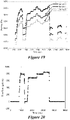
- Example 4 was conducted in the manner described above for Example 3 except using 1.57kg/L (13.1 ppg) mud.
- Figure 19 shows the pressure profile at 3 sensors with time at three flow rates.
- Figure 20 shows the mud pumping rate vs. time.
- non-Newtonian fluids A further complication of non-Newtonian fluids is time dependent (transient) behavior. Some fluids require a gradually increasing shear stress to maintain a constant strain rate and are called rheopectic. The opposite case of a fluid, which thins out with time and requires decreasing stress is termed thixotropic. Drilling fluids usually will exhibit a thixotropic behavior at the time circulation is started. This is due to a non-Newtonian parameter called "gel strength," which is the stress required to initiate circulation. The gel strength can help keep particles in suspension when circulation is stopped.
Landscapes
- Life Sciences & Earth Sciences (AREA)
- Engineering & Computer Science (AREA)
- Geology (AREA)
- Mining & Mineral Resources (AREA)
- Physics & Mathematics (AREA)
- Environmental & Geological Engineering (AREA)
- Fluid Mechanics (AREA)
- General Life Sciences & Earth Sciences (AREA)
- Geochemistry & Mineralogy (AREA)
- Geophysics (AREA)
- Measuring Volume Flow (AREA)
- Measuring Fluid Pressure (AREA)
Claims (14)
- Procédé de détermination d'un paramètre rhéologique d'un fluide dans un puits de forage, comprenant :la réception, en utilisant un dispositif de traitement (160), d'une pluralité de débits mesurés et d'une pluralité de mesures de pression différentielle correspondant à la pluralité de débits mesurés du fluide s'écoulant dans une région d'écoulement du puits de forage, dans lequel la pluralité de mesures de pression différentielle sont obtenues dans des conditions de fond de trou du puits de forage ;le stockage, en utilisant le dispositif de traitement (160), de la pluralité de débits mesurés et de la pluralité de mesures de pression différentielle correspondant à la pluralité de débits mesurés ;la génération, en utilisant le dispositif de traitement (160), d'une courbe d'écoulement sur la base de la pluralité de mesures de pression différentielle et de la pluralité de débits mesurés ;la détermination, en utilisant le dispositif de traitement (160), d'un indice de comportement d'écoulement pour le fluide à partir de la courbe d'écoulement ; etla détermination, en utilisant le dispositif de traitement (160), du paramètre rhéologique du fluide en utilisant la courbe d'écoulement et un modèle rhéologique ;dans lequel la région d'écoulement comprend une zone à l'intérieur d'un conduit situé dans le puits de forage.
- Procédé selon la revendication 1, dans lequel la réception, en utilisant un dispositif de traitement (160), d'une pluralité de mesures de pression différentielle correspondant à la pluralité de débits mesurés du fluide s'écoulant dans une région d'écoulement du puits de forage comprend :la réception, en utilisant le dispositif de traitement (160), d'une pluralité de mesures de pression correspondant à la pluralité de débits mesurés du fluide s'écoulant dans la région d'écoulement du puits de forage à partir d'une pluralité de capteurs de pression ; etle calcul, en utilisant le dispositif de traitement (160), de la pluralité de mesures de pression différentielle du fluide à partir de la pluralité de mesures de pression.
- Procédé selon la revendication 1 ou 2, dans lequel les étapes de génération et de détermination comprennent en outre la génération, en utilisant le dispositif de traitement (160), d'une courbe de pression sur la base de la pluralité de mesures de pression différentielle, et la détermination, en utilisant le dispositif de traitement (160), du paramètre rhéologique du fluide en utilisant la courbe de pression.
- Procédé selon l'une quelconque des revendications 1-3, dans lequel le modèle rhéologique comprend un modèle qui se rapporte à une contrainte de cisaillement et à une vitesse de cisaillement.
- Procédé selon l'une quelconque des revendications 1-4, dans lequel la pluralité de débits mesurés incluent au moins trois débits différents.
- Procédé selon l'une quelconque des revendications 1-5, comprenant en outre la correction, en utilisant le dispositif de traitement (160), de la pluralité de mesures de pression différentielle du fluide en fonction de l'excentricité entre le conduit et le puits de forage.
- Procédé selon la revendication 6, dans lequel la pluralité de mesures de pression différentielle du fluide sont corrigées en fonction de l'excentricité entre le conduit et le puits de forage en utilisant un modèle de tube équivalent, un modèle basé sur la corrélation, ou une combinaison de ceux-ci.
- Procédé selon l'une quelconque des revendications 1-7, comprenant en outre :la réception, en utilisant le dispositif de traitement (160), d'instants correspondant à chacune de la pluralité de mesures de pression différentielle du fluide ;la génération, en utilisant le dispositif de traitement (160), d'une courbe de pression dans le temps sur la base de la pluralité de mesures de pression différentielle du fluide ; etl'estimation, en utilisant le dispositif de traitement (160), d'une résistance de gel du fluide en utilisant la courbe de pression dans le temps.
- Procédé selon l'une quelconque des revendications 1-8, dans lequel le paramètre rhéologique inclut une contrainte de cisaillement est une vitesse de cisaillement du fluide.
- Procédé selon l'une quelconque des revendications 1-9, dans lequel le fluide comprend un fluide de forage.
- Procédé selon l'une quelconque des revendications 1-10, dans lequel la pluralité de capteurs de pression comprennent trois capteurs de pression.
- Système de détermination d'un paramètre rhéologique d'un fluide dans un puits de forage, comprenant :un conduit agencé dans un puits de forage ;un débitmètre configuré pour mesurer un débit du fluide s'écoulant dans le conduit ;une pluralité de capteurs de pression le long du conduit, configurés pour mesurer une pression du fluide dans le conduit dans des conditions de fond de trou du puits de forage ; etun dispositif de traitement (160) configuré pour :recevoir une pluralité de débits du fluide à partir du débitmètre ;recevoir une pluralité de mesures de pression différentielle du fluide à partir de la pluralité de capteurs de pression, dans lequel la pluralité de mesures de pression différentielle correspondent à la pluralité de débits ;stocker la pluralité de débits et la pluralité de mesures de pression différentielle correspondant à la pluralité de débits ;générer une courbe d'écoulement sur la base d'une pluralité de débits et de la pluralité de mesures de pression différentielle ; etdéterminer le paramètre rhéologique du fluide en utilisant la courbe d'écoulement et un modèle rhéologique.
- Système selon la revendication 12, dans lequel le modèle rhéologique comprend n'importe quel modèle qui se rapporte à une contrainte de cisaillement et à une vitesse de cisaillement.
- Système selon la revendication 12 ou la revendication 13, dans lequel le paramètre rhéologique inclut une contrainte de cisaillement est une vitesse de cisaillement du fluide.
Applications Claiming Priority (2)
| Application Number | Priority Date | Filing Date | Title |
|---|---|---|---|
| US201461992957P | 2014-05-14 | 2014-05-14 | |
| PCT/US2015/030783 WO2015175784A1 (fr) | 2014-05-14 | 2015-05-14 | Systèmes et procédés de détermination d'un paramètre rhéologique |
Publications (3)
| Publication Number | Publication Date |
|---|---|
| EP3143247A1 EP3143247A1 (fr) | 2017-03-22 |
| EP3143247A4 EP3143247A4 (fr) | 2018-02-28 |
| EP3143247B1 true EP3143247B1 (fr) | 2022-04-06 |
Family
ID=54480680
Family Applications (1)
| Application Number | Title | Priority Date | Filing Date |
|---|---|---|---|
| EP15792712.0A Active EP3143247B1 (fr) | 2014-05-14 | 2015-05-14 | Systèmes et procédés de détermination d'un paramètre rhéologique |
Country Status (4)
| Country | Link |
|---|---|
| US (2) | US9909413B2 (fr) |
| EP (1) | EP3143247B1 (fr) |
| SA (1) | SA516380304B1 (fr) |
| WO (1) | WO2015175784A1 (fr) |
Families Citing this family (20)
| Publication number | Priority date | Publication date | Assignee | Title |
|---|---|---|---|---|
| EP3143247B1 (fr) * | 2014-05-14 | 2022-04-06 | Board of Regents, The University of Texas System | Systèmes et procédés de détermination d'un paramètre rhéologique |
| GB2592494B (en) * | 2016-05-20 | 2022-03-30 | Halliburton Energy Services Inc | Managing equivalent circulating density during a wellbore operation |
| AU2016406805B2 (en) * | 2016-05-20 | 2021-12-16 | Halliburton Energy Services, Inc. | Managing equivalent circulating density during a wellbore operation |
| CA3041620A1 (fr) * | 2016-08-31 | 2018-03-08 | Board Of Regents, The University Of Texas System | Systemes et procedes permettant de determiner une caracteristique de fluide |
| US11352883B2 (en) | 2017-05-19 | 2022-06-07 | Baker Hughes, A Ge Company, Llc | In-situ rheology behavior characterization using data analytics techniques |
| US20190094119A1 (en) * | 2017-09-25 | 2019-03-28 | Schlumberger Technology Corporation | Pipe rheometer |
| US11378506B2 (en) | 2017-12-12 | 2022-07-05 | Baker Hughes, A Ge Company, Llc | Methods and systems for monitoring drilling fluid rheological characteristics |
| GB2590031B (en) * | 2018-12-20 | 2022-10-12 | Halliburton Energy Services Inc | Gel prediction modeling of wellbore fluids using rheology measurements |
| US20210063294A1 (en) * | 2019-09-03 | 2021-03-04 | Halliburton Energy Services, Inc. | In-line conical viscometer using shear stress sensors |
| EP4028747B1 (fr) * | 2019-09-09 | 2025-03-19 | The Texas A&M University System | Procédé et appareil de mesures de propriétés rhéologiques de fluides de forage en temps réel |
| NO347449B1 (en) * | 2020-02-24 | 2023-11-06 | Norce Innovation As | Determining rheological properties of fluids |
| CN111502579B (zh) * | 2020-04-27 | 2024-09-03 | 四川大学 | 一种自动报警的坑道保压取芯装备 |
| US11435274B2 (en) | 2020-06-04 | 2022-09-06 | Saudi Arabian Oil Company | Continuous mud rheology monitoring |
| CA3123674A1 (fr) | 2020-07-02 | 2022-01-02 | Opla Energy Ltd. | Dispositif et procede de rheologie |
| CN111982751A (zh) * | 2020-08-10 | 2020-11-24 | 清华大学 | 一种水泥基材料剪切稠化特性分析方法 |
| CN112727438B (zh) * | 2021-01-04 | 2022-02-18 | 西南石油大学 | 一种适用于超深井长裸眼井段的环空压降计算方法 |
| CN114970296B (zh) * | 2021-02-26 | 2025-03-25 | 中国石油天然气股份有限公司 | 流变参数处理方法、装置、计算机可读存储介质及处理器 |
| US12135266B2 (en) * | 2021-03-08 | 2024-11-05 | The Florida International University Board Of Trustees | Real time monitoring of non-Newtonian fluids |
| US12222268B1 (en) | 2023-07-20 | 2025-02-11 | Weatherford Technology Holdings, Llc | Non-intrusive rheometer for use in well operations |
| KR102862983B1 (ko) * | 2023-10-17 | 2025-09-23 | 한국지질자원연구원 | 유효 전단율 및 유효 점도에 의해 결정되는 프란틀 수를 갖는 유체가 유동하는 표면을 포함하는 유체 요소 |
Citations (2)
| Publication number | Priority date | Publication date | Assignee | Title |
|---|---|---|---|---|
| US4726219A (en) * | 1986-02-13 | 1988-02-23 | Atlantic Richfield Company | Method and system for determining fluid pressures in wellbores and tubular conduits |
| US20130025359A1 (en) * | 2011-07-29 | 2013-01-31 | Baker Hughes Incorporated | Viscometer for downhole use |
Family Cites Families (28)
| Publication number | Priority date | Publication date | Assignee | Title |
|---|---|---|---|---|
| US3468158A (en) | 1968-03-26 | 1969-09-23 | Texaco Inc | Method of and apparatus for determining rheological properties of non-newtonian fluids such as drilling fluids or the like |
| DE2928739C2 (de) | 1979-07-17 | 1981-03-19 | Ruhrgas Ag, 4300 Essen | Verfahren und Vorrichtung zur verbrennungslosen Messung und/oder Regelung der Wärmemengenzufuhr zu Gasverbrauchseinrichtungen |
| US4557142A (en) | 1983-10-13 | 1985-12-10 | Hutchinson-Hayes International, Inc. | Apparatus and method for real-time measurement of drilling fluid properties |
| US4680957A (en) | 1985-05-02 | 1987-07-21 | The Davey Company | Non-invasive, in-line consistency measurement of a non-newtonian fluid |
| FR2656373B1 (fr) * | 1989-12-26 | 1992-04-24 | Forex Neptune Sa | Methode de test in situ d'un fluide de forage. |
| ZA911996B (en) | 1990-03-16 | 1992-01-29 | Slurry Syst Pty Ltd | Method and apparatus for continuous on-line measurement of fluid or slurry rheology |
| NO300437B1 (no) | 1994-11-09 | 1997-05-26 | Jon Steinar Gudmundsson | Framgangsmåte for bestemmelse av strömningsrate i en fluidström, særlig en tofaseström |
| US6755079B1 (en) | 2000-03-27 | 2004-06-29 | Halliburton Energy Services, Inc. | Method and apparatus for determining fluid viscosity |
| US6659197B2 (en) | 2001-08-07 | 2003-12-09 | Schlumberger Technology Corporation | Method for determining drilling fluid properties downhole during wellbore drilling |
| US6691561B2 (en) | 2002-04-15 | 2004-02-17 | Gerneral Electric Company | Rheological measurement process |
| US7036362B2 (en) | 2003-01-20 | 2006-05-02 | Schlumberger Technology Corporation | Downhole determination of formation fluid properties |
| US20080264182A1 (en) * | 2003-08-22 | 2008-10-30 | Jones Richard T | Flow meter using sensitive differential pressure measurement |
| DK2192507T3 (da) | 2006-05-24 | 2013-10-14 | Maersk Olie & Gas | Strømningssimulation i et borehul eller en rørledning |
| US9732584B2 (en) * | 2007-04-02 | 2017-08-15 | Halliburton Energy Services, Inc. | Use of micro-electro-mechanical systems (MEMS) in well treatments |
| US20090308601A1 (en) * | 2008-06-12 | 2009-12-17 | Schlumberger Technology Corporation | Evaluating multiphase fluid flow in a wellbore using temperature and pressure measurements |
| US20110182141A1 (en) * | 2008-08-14 | 2011-07-28 | Schlumberger Technology Corporation | Method and system for monitoring a logging tool position in a borehole |
| US20100139374A1 (en) * | 2008-12-03 | 2010-06-10 | Dermody Daniel L | Methods for rheological testing of multiple samples and systems therefor |
| US8567525B2 (en) * | 2009-08-19 | 2013-10-29 | Smith International, Inc. | Method for determining fluid control events in a borehole using a dynamic annular pressure control system |
| US9903200B2 (en) * | 2011-07-19 | 2018-02-27 | Baker Hughes, A Ge Company, Llc | Viscosity measurement in a fluid analyzer sampling tool |
| WO2013017969A1 (fr) | 2011-08-04 | 2013-02-07 | Sik- The Swedish Institute For Food And Biotechnology | Système et procédé de visualisation et de caractérisation d'un fluide ; transducteur |
| US20130048380A1 (en) * | 2011-08-26 | 2013-02-28 | John Rasmus | Wellbore interval densities |
| US9394783B2 (en) * | 2011-08-26 | 2016-07-19 | Schlumberger Technology Corporation | Methods for evaluating inflow and outflow in a subterranean wellbore |
| US8881577B1 (en) | 2012-04-02 | 2014-11-11 | Agar Corporation, Ltd. | Method and system for analysis of rheological properties and composition of multi-component fluids |
| US9383476B2 (en) * | 2012-07-09 | 2016-07-05 | Weatherford Technology Holdings, Llc | In-well full-bore multiphase flowmeter for horizontal wellbores |
| EP2920403A1 (fr) * | 2012-11-15 | 2015-09-23 | BP Corporation North America Inc. | Systèmes et procédés pour déterminer une pression manométrique de la boue améliorée et une concentration de solides d'intervalle dans un système de puits à l'aide de multiples capteurs |
| US20150059446A1 (en) | 2013-03-15 | 2015-03-05 | Agar Corporation Ltd. | Method and system for analysis of rheological properties and composition of multi-component fluids |
| EP3143247B1 (fr) * | 2014-05-14 | 2022-04-06 | Board of Regents, The University of Texas System | Systèmes et procédés de détermination d'un paramètre rhéologique |
| CA3041620A1 (fr) * | 2016-08-31 | 2018-03-08 | Board Of Regents, The University Of Texas System | Systemes et procedes permettant de determiner une caracteristique de fluide |
-
2015
- 2015-05-14 EP EP15792712.0A patent/EP3143247B1/fr active Active
- 2015-05-14 US US14/712,564 patent/US9909413B2/en active Active
- 2015-05-14 WO PCT/US2015/030783 patent/WO2015175784A1/fr not_active Ceased
-
2016
- 2016-11-14 SA SA516380304A patent/SA516380304B1/ar unknown
-
2018
- 2018-03-01 US US15/909,187 patent/US20180291727A1/en not_active Abandoned
Patent Citations (2)
| Publication number | Priority date | Publication date | Assignee | Title |
|---|---|---|---|---|
| US4726219A (en) * | 1986-02-13 | 1988-02-23 | Atlantic Richfield Company | Method and system for determining fluid pressures in wellbores and tubular conduits |
| US20130025359A1 (en) * | 2011-07-29 | 2013-01-31 | Baker Hughes Incorporated | Viscometer for downhole use |
Also Published As
| Publication number | Publication date |
|---|---|
| US20150330213A1 (en) | 2015-11-19 |
| US20180291727A1 (en) | 2018-10-11 |
| EP3143247A4 (fr) | 2018-02-28 |
| EP3143247A1 (fr) | 2017-03-22 |
| US9909413B2 (en) | 2018-03-06 |
| SA516380304B1 (ar) | 2022-09-29 |
| WO2015175784A1 (fr) | 2015-11-19 |
Similar Documents
| Publication | Publication Date | Title |
|---|---|---|
| EP3143247B1 (fr) | Systèmes et procédés de détermination d'un paramètre rhéologique | |
| US10859481B2 (en) | Systems and methods for determining a fluid characteristic | |
| Vajargah et al. | Determination of drilling fluid rheology under downhole conditions by using real-time distributed pressure data | |
| US6659197B2 (en) | Method for determining drilling fluid properties downhole during wellbore drilling | |
| Liétard et al. | Fracture width logging while drilling and drilling mud/loss-circulation-material selection guidelines in naturally fractured reservoirs | |
| Postler | Pressure integrity test interpretation | |
| US11085287B2 (en) | Measurement of cement properties | |
| NO348483B1 (en) | Wellbore operations involving computational methods that produce sag profiles | |
| CA3053194C (fr) | Systemes et procedes de surveillance de l'integrite du ciment d'un tubage | |
| Yuan et al. | Differentiate drilling fluid thermal expansion, wellbore ballooning and real kick during flow check with an innovative combination of transient simulation and pumps off annular pressure while drilling | |
| Vajargah et al. | Automated drilling fluid rheology characterization with downhole pressure sensor data | |
| US10041344B2 (en) | Determining pressure within a sealed annulus | |
| Mostafavi et al. | Model-based uncertainty assessment of wellbore stability analyses and downhole pressure estimations | |
| Last et al. | Evaluation, impact, and management of casing deformation caused by tectonic forces in the Andean Foothills, Colombia | |
| US10753203B2 (en) | Systems and methods to identify and inhibit spider web borehole failure in hydrocarbon wells | |
| Rahman et al. | Analysis of a drilling mud-based system on the common problems related to coiled tubing application in slim-hole oil wells | |
| Gao et al. | Continued improvements on high-pressure/high-temperature drilling performance on wells with extremely narrow drilling windows-experiences from mud formulation to operational practices, shearwater project | |
| US20250092774A1 (en) | System and methods for determining gel breaking time of thixotropic drilling fluids | |
| Swanson et al. | Application of Novel Technologies in the Design and Engineering of Synthetic-Based Mud Used to Drill and Complete Horizontal, High-Temperature/High-Pressure Wells in the Central North Sea, Marnock Field | |
| Zhang et al. | Treatment of Losses Based on Root Cause and Fracture Width Analysis | |
| Smith et al. | Measuring Drilled Cuttings and Fluid Recovery by Real Time Mass Balance | |
| Silva et al. | Conformai mapping applied to the estimate of Surge and Swab geopressures | |
| Denney | Assuring Stability in Extended-Reach Wells: Analyses, Practices, and Mitigations |
Legal Events
| Date | Code | Title | Description |
|---|---|---|---|
| STAA | Information on the status of an ep patent application or granted ep patent |
Free format text: STATUS: THE INTERNATIONAL PUBLICATION HAS BEEN MADE |
|
| PUAI | Public reference made under article 153(3) epc to a published international application that has entered the european phase |
Free format text: ORIGINAL CODE: 0009012 |
|
| STAA | Information on the status of an ep patent application or granted ep patent |
Free format text: STATUS: REQUEST FOR EXAMINATION WAS MADE |
|
| 17P | Request for examination filed |
Effective date: 20161212 |
|
| AK | Designated contracting states |
Kind code of ref document: A1 Designated state(s): AL AT BE BG CH CY CZ DE DK EE ES FI FR GB GR HR HU IE IS IT LI LT LU LV MC MK MT NL NO PL PT RO RS SE SI SK SM TR |
|
| AX | Request for extension of the european patent |
Extension state: BA ME |
|
| DAV | Request for validation of the european patent (deleted) | ||
| DAX | Request for extension of the european patent (deleted) | ||
| A4 | Supplementary search report drawn up and despatched |
Effective date: 20180126 |
|
| RIC1 | Information provided on ipc code assigned before grant |
Ipc: E21B 47/06 20120101ALI20180122BHEP Ipc: E21B 47/00 20120101AFI20180122BHEP Ipc: E21B 49/08 20060101ALI20180122BHEP |
|
| STAA | Information on the status of an ep patent application or granted ep patent |
Free format text: STATUS: EXAMINATION IS IN PROGRESS |
|
| 17Q | First examination report despatched |
Effective date: 20190122 |
|
| GRAP | Despatch of communication of intention to grant a patent |
Free format text: ORIGINAL CODE: EPIDOSNIGR1 |
|
| STAA | Information on the status of an ep patent application or granted ep patent |
Free format text: STATUS: GRANT OF PATENT IS INTENDED |
|
| INTG | Intention to grant announced |
Effective date: 20211027 |
|
| GRAS | Grant fee paid |
Free format text: ORIGINAL CODE: EPIDOSNIGR3 |
|
| GRAA | (expected) grant |
Free format text: ORIGINAL CODE: 0009210 |
|
| STAA | Information on the status of an ep patent application or granted ep patent |
Free format text: STATUS: THE PATENT HAS BEEN GRANTED |
|
| AK | Designated contracting states |
Kind code of ref document: B1 Designated state(s): AL AT BE BG CH CY CZ DE DK EE ES FI FR GB GR HR HU IE IS IT LI LT LU LV MC MK MT NL NO PL PT RO RS SE SI SK SM TR |
|
| REG | Reference to a national code |
Ref country code: GB Ref legal event code: FG4D |
|
| RAP4 | Party data changed (patent owner data changed or rights of a patent transferred) |
Owner name: BOARD OF REGENTS, THE UNIVERSITY OF TEXAS SYSTEM |
|
| REG | Reference to a national code |
Ref country code: CH Ref legal event code: EP |
|
| REG | Reference to a national code |
Ref country code: AT Ref legal event code: REF Ref document number: 1481517 Country of ref document: AT Kind code of ref document: T Effective date: 20220415 |
|
| REG | Reference to a national code |
Ref country code: DE Ref legal event code: R096 Ref document number: 602015078069 Country of ref document: DE |
|
| REG | Reference to a national code |
Ref country code: IE Ref legal event code: FG4D |
|
| REG | Reference to a national code |
Ref country code: NO Ref legal event code: T2 Effective date: 20220406 |
|
| REG | Reference to a national code |
Ref country code: LT Ref legal event code: MG9D |
|
| REG | Reference to a national code |
Ref country code: NL Ref legal event code: MP Effective date: 20220406 |
|
| REG | Reference to a national code |
Ref country code: AT Ref legal event code: MK05 Ref document number: 1481517 Country of ref document: AT Kind code of ref document: T Effective date: 20220406 |
|
| PG25 | Lapsed in a contracting state [announced via postgrant information from national office to epo] |
Ref country code: NL Free format text: LAPSE BECAUSE OF FAILURE TO SUBMIT A TRANSLATION OF THE DESCRIPTION OR TO PAY THE FEE WITHIN THE PRESCRIBED TIME-LIMIT Effective date: 20220406 |
|
| PG25 | Lapsed in a contracting state [announced via postgrant information from national office to epo] |
Ref country code: SE Free format text: LAPSE BECAUSE OF FAILURE TO SUBMIT A TRANSLATION OF THE DESCRIPTION OR TO PAY THE FEE WITHIN THE PRESCRIBED TIME-LIMIT Effective date: 20220406 Ref country code: PT Free format text: LAPSE BECAUSE OF FAILURE TO SUBMIT A TRANSLATION OF THE DESCRIPTION OR TO PAY THE FEE WITHIN THE PRESCRIBED TIME-LIMIT Effective date: 20220808 Ref country code: LT Free format text: LAPSE BECAUSE OF FAILURE TO SUBMIT A TRANSLATION OF THE DESCRIPTION OR TO PAY THE FEE WITHIN THE PRESCRIBED TIME-LIMIT Effective date: 20220406 Ref country code: HR Free format text: LAPSE BECAUSE OF FAILURE TO SUBMIT A TRANSLATION OF THE DESCRIPTION OR TO PAY THE FEE WITHIN THE PRESCRIBED TIME-LIMIT Effective date: 20220406 Ref country code: GR Free format text: LAPSE BECAUSE OF FAILURE TO SUBMIT A TRANSLATION OF THE DESCRIPTION OR TO PAY THE FEE WITHIN THE PRESCRIBED TIME-LIMIT Effective date: 20220707 Ref country code: FI Free format text: LAPSE BECAUSE OF FAILURE TO SUBMIT A TRANSLATION OF THE DESCRIPTION OR TO PAY THE FEE WITHIN THE PRESCRIBED TIME-LIMIT Effective date: 20220406 Ref country code: ES Free format text: LAPSE BECAUSE OF FAILURE TO SUBMIT A TRANSLATION OF THE DESCRIPTION OR TO PAY THE FEE WITHIN THE PRESCRIBED TIME-LIMIT Effective date: 20220406 Ref country code: BG Free format text: LAPSE BECAUSE OF FAILURE TO SUBMIT A TRANSLATION OF THE DESCRIPTION OR TO PAY THE FEE WITHIN THE PRESCRIBED TIME-LIMIT Effective date: 20220706 Ref country code: AT Free format text: LAPSE BECAUSE OF FAILURE TO SUBMIT A TRANSLATION OF THE DESCRIPTION OR TO PAY THE FEE WITHIN THE PRESCRIBED TIME-LIMIT Effective date: 20220406 |
|
| PG25 | Lapsed in a contracting state [announced via postgrant information from national office to epo] |
Ref country code: RS Free format text: LAPSE BECAUSE OF FAILURE TO SUBMIT A TRANSLATION OF THE DESCRIPTION OR TO PAY THE FEE WITHIN THE PRESCRIBED TIME-LIMIT Effective date: 20220406 Ref country code: PL Free format text: LAPSE BECAUSE OF FAILURE TO SUBMIT A TRANSLATION OF THE DESCRIPTION OR TO PAY THE FEE WITHIN THE PRESCRIBED TIME-LIMIT Effective date: 20220406 Ref country code: LV Free format text: LAPSE BECAUSE OF FAILURE TO SUBMIT A TRANSLATION OF THE DESCRIPTION OR TO PAY THE FEE WITHIN THE PRESCRIBED TIME-LIMIT Effective date: 20220406 Ref country code: IS Free format text: LAPSE BECAUSE OF FAILURE TO SUBMIT A TRANSLATION OF THE DESCRIPTION OR TO PAY THE FEE WITHIN THE PRESCRIBED TIME-LIMIT Effective date: 20220806 |
|
| REG | Reference to a national code |
Ref country code: DE Ref legal event code: R119 Ref document number: 602015078069 Country of ref document: DE |
|
| REG | Reference to a national code |
Ref country code: CH Ref legal event code: PL |
|
| REG | Reference to a national code |
Ref country code: BE Ref legal event code: MM Effective date: 20220531 |
|
| PG25 | Lapsed in a contracting state [announced via postgrant information from national office to epo] |
Ref country code: SM Free format text: LAPSE BECAUSE OF FAILURE TO SUBMIT A TRANSLATION OF THE DESCRIPTION OR TO PAY THE FEE WITHIN THE PRESCRIBED TIME-LIMIT Effective date: 20220406 Ref country code: SK Free format text: LAPSE BECAUSE OF FAILURE TO SUBMIT A TRANSLATION OF THE DESCRIPTION OR TO PAY THE FEE WITHIN THE PRESCRIBED TIME-LIMIT Effective date: 20220406 Ref country code: RO Free format text: LAPSE BECAUSE OF FAILURE TO SUBMIT A TRANSLATION OF THE DESCRIPTION OR TO PAY THE FEE WITHIN THE PRESCRIBED TIME-LIMIT Effective date: 20220406 Ref country code: MC Free format text: LAPSE BECAUSE OF FAILURE TO SUBMIT A TRANSLATION OF THE DESCRIPTION OR TO PAY THE FEE WITHIN THE PRESCRIBED TIME-LIMIT Effective date: 20220406 Ref country code: LU Free format text: LAPSE BECAUSE OF NON-PAYMENT OF DUE FEES Effective date: 20220514 Ref country code: LI Free format text: LAPSE BECAUSE OF NON-PAYMENT OF DUE FEES Effective date: 20220531 Ref country code: EE Free format text: LAPSE BECAUSE OF FAILURE TO SUBMIT A TRANSLATION OF THE DESCRIPTION OR TO PAY THE FEE WITHIN THE PRESCRIBED TIME-LIMIT Effective date: 20220406 Ref country code: DK Free format text: LAPSE BECAUSE OF FAILURE TO SUBMIT A TRANSLATION OF THE DESCRIPTION OR TO PAY THE FEE WITHIN THE PRESCRIBED TIME-LIMIT Effective date: 20220406 Ref country code: CZ Free format text: LAPSE BECAUSE OF FAILURE TO SUBMIT A TRANSLATION OF THE DESCRIPTION OR TO PAY THE FEE WITHIN THE PRESCRIBED TIME-LIMIT Effective date: 20220406 Ref country code: CH Free format text: LAPSE BECAUSE OF NON-PAYMENT OF DUE FEES Effective date: 20220531 |
|
| PLBE | No opposition filed within time limit |
Free format text: ORIGINAL CODE: 0009261 |
|
| STAA | Information on the status of an ep patent application or granted ep patent |
Free format text: STATUS: NO OPPOSITION FILED WITHIN TIME LIMIT |
|
| 26N | No opposition filed |
Effective date: 20230110 |
|
| PG25 | Lapsed in a contracting state [announced via postgrant information from national office to epo] |
Ref country code: AL Free format text: LAPSE BECAUSE OF FAILURE TO SUBMIT A TRANSLATION OF THE DESCRIPTION OR TO PAY THE FEE WITHIN THE PRESCRIBED TIME-LIMIT Effective date: 20220406 |
|
| PG25 | Lapsed in a contracting state [announced via postgrant information from national office to epo] |
Ref country code: IE Free format text: LAPSE BECAUSE OF NON-PAYMENT OF DUE FEES Effective date: 20220514 Ref country code: FR Free format text: LAPSE BECAUSE OF NON-PAYMENT OF DUE FEES Effective date: 20220606 |
|
| PG25 | Lapsed in a contracting state [announced via postgrant information from national office to epo] |
Ref country code: SI Free format text: LAPSE BECAUSE OF FAILURE TO SUBMIT A TRANSLATION OF THE DESCRIPTION OR TO PAY THE FEE WITHIN THE PRESCRIBED TIME-LIMIT Effective date: 20220406 Ref country code: DE Free format text: LAPSE BECAUSE OF NON-PAYMENT OF DUE FEES Effective date: 20221201 Ref country code: BE Free format text: LAPSE BECAUSE OF NON-PAYMENT OF DUE FEES Effective date: 20220531 |
|
| PG25 | Lapsed in a contracting state [announced via postgrant information from national office to epo] |
Ref country code: IT Free format text: LAPSE BECAUSE OF FAILURE TO SUBMIT A TRANSLATION OF THE DESCRIPTION OR TO PAY THE FEE WITHIN THE PRESCRIBED TIME-LIMIT Effective date: 20220406 |
|
| PG25 | Lapsed in a contracting state [announced via postgrant information from national office to epo] |
Ref country code: HU Free format text: LAPSE BECAUSE OF FAILURE TO SUBMIT A TRANSLATION OF THE DESCRIPTION OR TO PAY THE FEE WITHIN THE PRESCRIBED TIME-LIMIT; INVALID AB INITIO Effective date: 20150514 |
|
| PG25 | Lapsed in a contracting state [announced via postgrant information from national office to epo] |
Ref country code: MK Free format text: LAPSE BECAUSE OF FAILURE TO SUBMIT A TRANSLATION OF THE DESCRIPTION OR TO PAY THE FEE WITHIN THE PRESCRIBED TIME-LIMIT Effective date: 20220406 Ref country code: CY Free format text: LAPSE BECAUSE OF FAILURE TO SUBMIT A TRANSLATION OF THE DESCRIPTION OR TO PAY THE FEE WITHIN THE PRESCRIBED TIME-LIMIT Effective date: 20220406 |
|
| PG25 | Lapsed in a contracting state [announced via postgrant information from national office to epo] |
Ref country code: MT Free format text: LAPSE BECAUSE OF FAILURE TO SUBMIT A TRANSLATION OF THE DESCRIPTION OR TO PAY THE FEE WITHIN THE PRESCRIBED TIME-LIMIT Effective date: 20220406 |
|
| PG25 | Lapsed in a contracting state [announced via postgrant information from national office to epo] |
Ref country code: BG Free format text: LAPSE BECAUSE OF FAILURE TO SUBMIT A TRANSLATION OF THE DESCRIPTION OR TO PAY THE FEE WITHIN THE PRESCRIBED TIME-LIMIT Effective date: 20220406 |
|
| PG25 | Lapsed in a contracting state [announced via postgrant information from national office to epo] |
Ref country code: BG Free format text: LAPSE BECAUSE OF FAILURE TO SUBMIT A TRANSLATION OF THE DESCRIPTION OR TO PAY THE FEE WITHIN THE PRESCRIBED TIME-LIMIT Effective date: 20220406 |
|
| PGFP | Annual fee paid to national office [announced via postgrant information from national office to epo] |
Ref country code: GB Payment date: 20250410 Year of fee payment: 11 |
|
| PGFP | Annual fee paid to national office [announced via postgrant information from national office to epo] |
Ref country code: NO Payment date: 20250509 Year of fee payment: 11 |
|
| PG25 | Lapsed in a contracting state [announced via postgrant information from national office to epo] |
Ref country code: TR Free format text: LAPSE BECAUSE OF FAILURE TO SUBMIT A TRANSLATION OF THE DESCRIPTION OR TO PAY THE FEE WITHIN THE PRESCRIBED TIME-LIMIT Effective date: 20220406 |