EP3143281B1 - Procédé de fonctionnement d'un système de pompe et un système de pompe - Google Patents
Procédé de fonctionnement d'un système de pompe et un système de pompe Download PDFInfo
- Publication number
- EP3143281B1 EP3143281B1 EP15716443.5A EP15716443A EP3143281B1 EP 3143281 B1 EP3143281 B1 EP 3143281B1 EP 15716443 A EP15716443 A EP 15716443A EP 3143281 B1 EP3143281 B1 EP 3143281B1
- Authority
- EP
- European Patent Office
- Prior art keywords
- pump
- control device
- operating
- control
- spray gun
- Prior art date
- Legal status (The legal status is an assumption and is not a legal conclusion. Google has not performed a legal analysis and makes no representation as to the accuracy of the status listed.)
- Active
Links
Images


Classifications
-
- B—PERFORMING OPERATIONS; TRANSPORTING
- B05—SPRAYING OR ATOMISING IN GENERAL; APPLYING FLUENT MATERIALS TO SURFACES, IN GENERAL
- B05B—SPRAYING APPARATUS; ATOMISING APPARATUS; NOZZLES
- B05B12/00—Arrangements for controlling delivery; Arrangements for controlling the spray area
- B05B12/14—Arrangements for controlling delivery; Arrangements for controlling the spray area for supplying a selected one of a plurality of liquids or other fluent materials or several in selected proportions to a spray apparatus, e.g. to a single spray outlet
- B05B12/1418—Arrangements for controlling delivery; Arrangements for controlling the spray area for supplying a selected one of a plurality of liquids or other fluent materials or several in selected proportions to a spray apparatus, e.g. to a single spray outlet for supplying several liquids or other fluent materials in selected proportions to a single spray outlet
-
- B—PERFORMING OPERATIONS; TRANSPORTING
- B05—SPRAYING OR ATOMISING IN GENERAL; APPLYING FLUENT MATERIALS TO SURFACES, IN GENERAL
- B05B—SPRAYING APPARATUS; ATOMISING APPARATUS; NOZZLES
- B05B7/00—Spraying apparatus for discharge of liquids or other fluent materials from two or more sources, e.g. of liquid and air, of powder and gas
- B05B7/24—Spraying apparatus for discharge of liquids or other fluent materials from two or more sources, e.g. of liquid and air, of powder and gas with means, e.g. a container, for supplying liquid or other fluent material to a discharge device
-
- F—MECHANICAL ENGINEERING; LIGHTING; HEATING; WEAPONS; BLASTING
- F04—POSITIVE - DISPLACEMENT MACHINES FOR LIQUIDS; PUMPS FOR LIQUIDS OR ELASTIC FLUIDS
- F04B—POSITIVE-DISPLACEMENT MACHINES FOR LIQUIDS; PUMPS
- F04B17/00—Pumps characterised by combination with, or adaptation to, specific driving engines or motors
- F04B17/03—Pumps characterised by combination with, or adaptation to, specific driving engines or motors driven by electric motors
-
- F—MECHANICAL ENGINEERING; LIGHTING; HEATING; WEAPONS; BLASTING
- F04—POSITIVE - DISPLACEMENT MACHINES FOR LIQUIDS; PUMPS FOR LIQUIDS OR ELASTIC FLUIDS
- F04B—POSITIVE-DISPLACEMENT MACHINES FOR LIQUIDS; PUMPS
- F04B17/00—Pumps characterised by combination with, or adaptation to, specific driving engines or motors
- F04B17/06—Mobile combinations
-
- F—MECHANICAL ENGINEERING; LIGHTING; HEATING; WEAPONS; BLASTING
- F04—POSITIVE - DISPLACEMENT MACHINES FOR LIQUIDS; PUMPS FOR LIQUIDS OR ELASTIC FLUIDS
- F04B—POSITIVE-DISPLACEMENT MACHINES FOR LIQUIDS; PUMPS
- F04B19/00—Machines or pumps having pertinent characteristics not provided for in, or of interest apart from, groups F04B1/00 - F04B17/00
- F04B19/20—Other positive-displacement pumps
- F04B19/22—Other positive-displacement pumps of reciprocating-piston type
-
- F—MECHANICAL ENGINEERING; LIGHTING; HEATING; WEAPONS; BLASTING
- F04—POSITIVE - DISPLACEMENT MACHINES FOR LIQUIDS; PUMPS FOR LIQUIDS OR ELASTIC FLUIDS
- F04B—POSITIVE-DISPLACEMENT MACHINES FOR LIQUIDS; PUMPS
- F04B23/00—Pumping installations or systems
- F04B23/02—Pumping installations or systems having reservoirs
-
- F—MECHANICAL ENGINEERING; LIGHTING; HEATING; WEAPONS; BLASTING
- F04—POSITIVE - DISPLACEMENT MACHINES FOR LIQUIDS; PUMPS FOR LIQUIDS OR ELASTIC FLUIDS
- F04B—POSITIVE-DISPLACEMENT MACHINES FOR LIQUIDS; PUMPS
- F04B23/00—Pumping installations or systems
- F04B23/04—Combinations of two or more pumps
- F04B23/06—Combinations of two or more pumps the pumps being all of reciprocating positive-displacement type
-
- F—MECHANICAL ENGINEERING; LIGHTING; HEATING; WEAPONS; BLASTING
- F04—POSITIVE - DISPLACEMENT MACHINES FOR LIQUIDS; PUMPS FOR LIQUIDS OR ELASTIC FLUIDS
- F04B—POSITIVE-DISPLACEMENT MACHINES FOR LIQUIDS; PUMPS
- F04B49/00—Control, e.g. of pump delivery, or pump pressure of, or safety measures for, machines, pumps, or pumping installations, not otherwise provided for, or of interest apart from, groups F04B1/00 - F04B47/00
- F04B49/06—Control using electricity
-
- F—MECHANICAL ENGINEERING; LIGHTING; HEATING; WEAPONS; BLASTING
- F04—POSITIVE - DISPLACEMENT MACHINES FOR LIQUIDS; PUMPS FOR LIQUIDS OR ELASTIC FLUIDS
- F04B—POSITIVE-DISPLACEMENT MACHINES FOR LIQUIDS; PUMPS
- F04B49/00—Control, e.g. of pump delivery, or pump pressure of, or safety measures for, machines, pumps, or pumping installations, not otherwise provided for, or of interest apart from, groups F04B1/00 - F04B47/00
- F04B49/06—Control using electricity
- F04B49/065—Control using electricity and making use of computers
-
- F—MECHANICAL ENGINEERING; LIGHTING; HEATING; WEAPONS; BLASTING
- F04—POSITIVE - DISPLACEMENT MACHINES FOR LIQUIDS; PUMPS FOR LIQUIDS OR ELASTIC FLUIDS
- F04B—POSITIVE-DISPLACEMENT MACHINES FOR LIQUIDS; PUMPS
- F04B49/00—Control, e.g. of pump delivery, or pump pressure of, or safety measures for, machines, pumps, or pumping installations, not otherwise provided for, or of interest apart from, groups F04B1/00 - F04B47/00
- F04B49/10—Other safety measures
-
- G—PHYSICS
- G05—CONTROLLING; REGULATING
- G05B—CONTROL OR REGULATING SYSTEMS IN GENERAL; FUNCTIONAL ELEMENTS OF SUCH SYSTEMS; MONITORING OR TESTING ARRANGEMENTS FOR SUCH SYSTEMS OR ELEMENTS
- G05B19/00—Program-control systems
- G05B19/02—Program-control systems electric
- G05B19/04—Program control other than numerical control, i.e. in sequence controllers or logic controllers
- G05B19/042—Program control other than numerical control, i.e. in sequence controllers or logic controllers using digital processors
- G05B19/0426—Programming the control sequence
-
- G—PHYSICS
- G05—CONTROLLING; REGULATING
- G05B—CONTROL OR REGULATING SYSTEMS IN GENERAL; FUNCTIONAL ELEMENTS OF SUCH SYSTEMS; MONITORING OR TESTING ARRANGEMENTS FOR SUCH SYSTEMS OR ELEMENTS
- G05B2219/00—Program-control systems
- G05B2219/30—Nc systems
- G05B2219/32—Operator till task planning
- G05B2219/32096—Batch, recipe configuration for flexible batch control
Definitions
- the invention relates to a method for controlling a pump system and a pump system with a pump unit for dispensing multi-component material under pressure with a spray gun, the pump unit comprising a pump device, a mixer and a spray gun, the pump device comprising at least two pumps for conveying component material and each has assigned liquid storage for storing component material, the pump system having a control device, the control device comprising a control device and a database.
- Such pump systems and methods for controlling or operating pump systems are sufficiently known from the prior art and are regularly used for surface coating or for applying or spraying a multicomponent material onto a surface.
- the multi-component material consists of one or more base component materials and a hardener component material, these component materials being stored separately in liquid stores. Any liquid storage a pump is assigned to convey the respective component material. Pneumatically driven piston pumps are preferably used here, although other types of pumps can also be used.
- the component materials are conveyed to a so-called mixer by means of the respective pumps and mixed within the mixer in such a way that the multicomponent material thus formed can harden.
- the multicomponent material is conveyed from the mixer under pressure to a so-called spray gun.
- the spray gun does not necessarily have to have a gun shape, but can be any type of nozzle with which the multicomponent material can be sprayed onto a surface by atomization. This can preferably be done using compressed air.
- one or more heaters can also be provided for tempering the component material.
- the pumps and the liquid store together form a pump device which can be operated or controlled by an operator via an operating device.
- such a pump device is equipped so that it can be transported so that it can easily be placed near the objects to be coated.
- the pump device can then be switched on and off via the operating device, it also being possible to set a mixing ratio of the component materials on the operating device.
- Such an adjustment is made regularly by varying the respective delivery rate of the pumps.
- the operating device can therefore also have various sensors, flow meters, stroke length meters or similar means for determining and influencing a delivery rate of the pumps.
- a delivery line of the pumps or the mixer and the spray gun must always be flushed after use or, for example, when changing colors.
- the control device therefore often also has a so-called flushing function.
- a pump unit formed from a pump device, a mixer and a spray gun is used, for example, for coating surfaces with corrosion protection or paints on or in ships, metal structures or industrial systems in situ. It is essential here that the pump unit can be easily transported by an operator and put into operation at the respective work station.
- a delivery line from the pump device to the spray gun can have a length of a few meters to a few hundred meters. This is particularly the case when a surface coating is carried out in places that are difficult to access, such as inside a ship's hull.
- the operator concerned applies the multi-component material to the surface to be coated with the spray gun, the operator continuously monitoring a work result during coating and possibly making corrective settings on the operator control device, such as changing a mixing ratio previously set by them . Furthermore, the operator must continuously monitor a fault-free function of the pump unit and an adequate filling of the liquid storage. If, for example, component material cannot be replenished, the operator may only become aware of this fact after a faulty order, for example without a hardener. This is particularly important when the delivery line is particularly long, and possible changes to the pump device only become noticeable to the operator when the spray gun is applied.
- a recipe contains, for example, information about suitable combinations of component material from the manufacturer and their mixing ratios, range information of mixing ratios, processing temperatures of component material, environmental parameters such as temperature and air humidity as well as range information.
- a recipe contains, for example, information about suitable combinations of component material from the manufacturer and their mixing ratios, range information of mixing ratios, processing temperatures of component material, environmental parameters such as temperature and air humidity as well as range information.
- the work result is then regularly checked and the operating parameters of the pump device or pump unit are adjusted as part of the recipe, the recipe in question then regularly being procured, kept at the pump unit and reviewed, which takes a lot of time and further knowledge in the field of spraying and painting technology is required.
- Different manufacturers also make different statements in recipes for component materials.
- the recipes themselves are tested and verified by the manufacturers of the component materials under laboratory conditions. So it may be that within the scope of a real application of a recipe with a pump unit, the recipe specified by the manufacturer can be deviated, because the manufacturer could not easily simulate the real working conditions for working out the recipe or these working conditions were not previously planned .
- environmental influences such as solar radiation, wind, air humidity, air temperature, temperature of the surface to be coated and other, other factors can certainly lead to a satisfactory work result, which is no longer within the scope of a recipe specified by the manufacturer.
- working conditions or environmental parameters can also lead to inadequate work results, even though the specifications specified by the manufacturer in a recipe have been observed.
- a manufacturer of component materials always endeavors to publish recipes for the component materials that are verified with sufficient certainty and can be reworked, which means that the recipes provide a sufficient safety reserve with regard to the information.
- the pump system has two pumps, each with associated liquid stores, a static mixer and a spray gun, which form a pump unit.
- the pump unit also has a device for controlling the pumps or valves.
- the DE 11 2011 103835 T5 shows a pump system with two independently formed pumps, each for a component material, the pumps each having control devices that can be connected to one another. This connection takes place via a so-called interface component, via which a user can also select a desired mixing ratio of the component materials.
- a pump is in the DE 10 2012 104214 A1 described, wherein the pump has a passive transponder that is wirelessly configurable by means of a control device.
- software of a control device of the pump is to be configured by contactless data exchange. This can be done using a so-called "app" a mobile phone.
- configuration can also be carried out via the Internet and a central database. For example, user information data of the pump manufacturer can then also be transmitted.
- the present invention is therefore based on the object of proposing a method for controlling a pump system and a pump system which enables the pump system to be easily adapted to different component materials.
- the pump unit comprises a pump device, a mixer and a spray gun, the pump device comprising at least two pumps for conveying component material and in each case associated liquid storage for storing component material
- the pump system has a control device, the control device comprises a control device and a database, recipes for mixing multi-component materials being stored in the database, the database being synchronized with at least one further external database at regular intervals or as requested by the control device with the control unit, the pump unit is controlled as a function of a recipe.
- the control device of the pump system consequently controls the pump unit or the pump device, for example by specifying a mixing ratio. Because the control device has the control device with the database, the control device can the pump device can be controlled directly in such a way that the pump device is given a mixing ratio by the control device in accordance with a recipe stored in the database. This specification can be made, for example, by means of a data connection between the control device and the pump device, it being possible for a delivery quantity of the respective pumps to be adapted according to the recipe. Operating the pump system is simplified by storing the recipe in the database in such a way that the recipe is always available directly on the pump system and does not have to be procured or searched for.
- the associated recipe can also be easily selected without the need for further adjustment of the pump device or of the delivery rates of the pumps. Rather, it is provided that the control unit automatically controls the pump unit or the pump of the pump unit without an operator having to deal with the details given in the recipes. This considerably simplifies operation of the pump system, in which case less qualified operators can also be entrusted with operating the pump system.
- the pump device can have an operating device by means of which the pump device can be controlled, wherein the control device together with the operating device can form a control unit by means of which the pump unit can be controlled.
- the control device can be arranged at a spatial distance from the pump unit, and data can be exchanged between the control device and the operating devices.
- data can be exchanged between the control device and the operating devices.
- the operating device can communicate with the control device via the data exchange.
- the control device it cannot be arranged on the pump device, that is to say the pumps or the operating device, but can be spatially separated from the pump device, since there is no need for a mechanically constructive connection between the pump device and the control device.
- a spatial or local separation is understood to mean a separation of the objects of the pump device and the control device, it being possible for there to be a line connection between the operating device and the control device.
- the operating device and the control device can be spatially separated, a range of functions of an operating device known from the prior art can be divided or significantly reduced between the operating device and the control device. This is particularly advantageous when an operator has to work under difficult environmental conditions, such as in a ship's hull, and has little opportunity to monitor the pump device or the operating device for correct functioning. This can then be done via the control device, which can be locally independent of the pump device.
- the control unit can then also have a smaller scope of functionality than the prior art, so that less well-trained operators can also be used to handle the pump device. Functionalities whose operation requires a higher level of qualification are then carried out by the control device.
- control device can be supplied with data on a fill level of the liquid store or a mixing ratio or a delivery volume of the respective pumps from the operating device.
- control device can be used to set the operating device further, for example to preset a mixing ratio.
- Environmental parameters, operating states, operating parameters and / or error messages of the pump device can advantageously be continuously used by the control unit for an operating period Database can be saved.
- a deterioration in a work result that occurs, for example, during operation of the pump device or the pump system can then be subsequently traced through a review of the stored data or a cause for the deterioration can be determined.
- control device can process environmental parameters, operating states, operating parameters and / or error messages, the control device being able to adapt or change the recipes in the database.
- the recipes stored in the database can be changed by the control device.
- the formulations developed under test conditions by manufacturers of component materials can thus be adapted to real environmental conditions during operation of the pump system. If necessary, it is then also possible to use mixing ratios for component materials that would not be permitted according to a recipe, but which, under certain conditions, actually deliver an excellent work result.
- the parameters deviating from the recipes can, for example, be tried out by an operator on a trial basis and, if successful or unsuccessful, can be stored in the database via the control device by adapting or changing the existing recipes.
- the control device can also be used to exchange data with an external network.
- An external network is understood to mean a network that cannot be assigned to the pump system. Such a network can be, for example, an intranet or the Internet. It is irrelevant how the communication with the external network takes place. This can be done via network cables as well as a wireless radio connection. Through the Communication with the external network offers countless possibilities for controlling or influencing the control device.
- the control device can thus provide an interface for operating the control device in the external network, that is to say the control device can be operated directly via the external network via computers connected to the external network. There is of course the possibility to limit and / or release rights for the respective operator by the control device.
- pump systems can also be connected to the external network or connected to them, so that these pump systems can be controlled or operated via the external network.
- the pump systems or the pump system connected to the external network can exchange data with a manufacturer of the pump system via the respective control devices.
- the manufacturer of a defective pump system can immediately access error messages or other system information if necessary.
- the manufacturer can also carry out software updates of the control device and influence the function of the control device.
- the manufacturer can use the data obtained from the control device (s) to transmit statistics that indicate the frequency of errors or user behavior, from which an optimization of the pump system can be derived.
- the database is synchronized with at least one further external database at regular time intervals or as requested by the control device.
- the recipes in the database are synchronized with recipes from the external database. It is then possible to transfer recipes changed by a manufacturer of component material into the database as required or automatically.
- the database can be linked to the other external database be connected to a manufacturer of the pump system or to a manufacturer of the component material. It is then also possible for the need to order component material to be signaled at the control device, or for an order process to be triggered automatically by the manufacturer.
- the database can also be connected to a plurality of further, external databases from different manufacturers.
- a user of the pump system can also change the recipes in the database, the changed recipes then being able to be transferred to the further external database.
- Manufacturers of component material can thus gain knowledge of the real environmental and usage conditions in which the component material is actually used or can be used.
- the control device can also recognize a type of spray gun, mixer and / or pump device, wherein the control device can correct the recipes taking into account the respective type. It is thus possible to optimally adapt the respective recipe to the spray gun, the mixer and / or the pump device that is currently being used. If necessary, the pump device can also have one or more heaters, which can then also be taken into account by the control device when changing or adapting the recipe. This makes it possible to further relieve an operator of possible setting and monitoring tasks.
- control device can check the plausibility of environmental parameters, operating states, operating parameters and / or error messages, taking into account the recipes.
- the pump device or the pump unit can have a sensor for measuring an ambient temperature the control device can determine by means of a simple actual / target comparison whether the component material can be processed or injected at the measured ambient temperature. Since the recipes include a number of parameters and range specifications, which can be related to each other, the control device can thus check the setting or operation of the pump unit within the scope of the respective recipe.
- Ambient parameters, operating states, operating parameters and / or error messages of the pump device can be transmitted from the operating device to the control device, wherein the control device can further process the environmental parameters, operating states, operating parameters and / or error messages.
- a fill level of a liquid reservoir of the pump device can be continuously detected by the operating device, the fill level then being able to be transmitted to the control device.
- the control device can carry out a number of further method steps when the level falls below a predetermined level. For example, the control device can issue a level warning or automatically request a subsequent delivery of component material.
- Operating conditions or operating parameters can also be interpreted by the control device in such a way that a maintenance interval has been reached and maintenance must be carried out. Error messages can be used by the control device to automatically request spare parts.
- Environmental parameters, operating conditions, operating parameters and / or error messages of the spray gun can also be transmitted from the spray gun to the control device, the control device being able to correct the recipes taking into account the respective environmental parameters, operating conditions, operating parameters and / or error messages of the spray gun. Consequently, the spray gun, like the pump device, can supply the aforementioned information or data transmit the control device such that the recipes stored in the database or the recipe currently used can be corrected on the basis of the current data situation.
- the spray gun can thus have a number of sensors by means of which the aforementioned data can be obtained.
- the spray gun can have an infrared temperature sensor with which a surface temperature of a surface to be coated can be measured continuously.
- Further parameters such as an ambient temperature and a temperature of the supplied component material, can also be determined by the spray gun. From the measured temperature data, it can be derived whether, according to the recipe used, the multi-component material can be sprayed with a satisfactory work result or whether a satisfactory work result can nevertheless be achieved contrary to the recipe, that is to say in the event of environmental conditions deviating from the recipe.
- the control device or the control device can correct the recipe or also save a user-specific recipe.
- control device can create a written documentation of the environmental parameters, operating states, operating parameters and / or error messages for an operating period.
- written documentation In the case of defects or warranty claims, it can be used as evidence of faultless execution of the work.
- the operating device and / or the control device can transmit environmental parameters, operating states, operating parameters and / or error messages of the pump device to the spray gun.
- the aforementioned data can also be displayed on the spray gun, so that an operator receives immediate knowledge of, for example, an error message or a fill level in a liquid reservoir. This is particularly advantageous if the operator works with the spray gun with the spray gun at a large distance from the pump device.
- status messages such as a pressure or a temperature
- the control device can be transmitted to the operating device and / or the spray gun and displayed there. It is then possible to provide an operator directly on the spray gun or also on the pump device with information relevant to the operator for performing the work task.
- the data exchange between the control device and the operating device can take place wirelessly.
- a line connection between the operating device and the control device can then be completely dispensed with.
- a wireless connection can be easily established, for example, by a radio connection within a common frequency band. It will then also be possible to ensure data exchange with the operating device if it has been set up in a location that is difficult to access.
- a plurality of pump devices can then also be easily monitored using the control device.
- the control device can then be positioned on, for example, company premises within an office building, with the control device being able to monitor and control various pump devices located on the company premises via the data exchange. It is then also possible to monitor and statistically evaluate the use of the respective pump devices, their utilization, a current local position, and an operating behavior.
- control commands from the operating device can be overlaid by control commands from the control device. It can then be ensured that any operating errors by an operator when operating the operating device can be corrected by the control device. For example, software of the operating device can then also be updated automatically by the control device. It is also conceivable to limit a possible mixing ratio of component materials to one area via the control device, so that an operator can only make settings within this area.
- Control commands and / or operating settings for the pump device can be transmitted from the control device to the operating device.
- the control device can consequently make settings such as mixing ratios, pressures etc. directly to the operating device transmit the pump device so that an operator no longer has to make these settings on the operating device.
- a control command for example for starting up the pump device, can also be passed on to the operating device.
- the control device can continuously adapt the control commands and / or operating settings on the basis of changed environmental parameters, operating states and / or operating parameters.
- the control commands transmitted from the control device to the operating device can be adapted as a function of the data transmitted from the operating device to the control device. This adjustment can already be carried out as part of a simple regulation with a control element.
- the control can be carried out on the basis of, for example, a single environmental parameter, and a comparatively complex control can also be carried out with a large number of data recorded at the same time.
- the operating device can be configured using the control device. This means that the operating device can be preset by means of the control device such that an operator no longer has to make any further adjustments to the operating device.
- a status message can be sent to an external network by means of the control device, depending on the environmental parameters, operating states, operating parameters and / or error messages.
- a status message can be, for example, an error message that is sent to a manufacturer of the pump system. The manufacturer is thus informed of a possible failure of the pump system or components of the pump system at an early stage and can use the transmitted status messages to narrow down or recognize an error without being on site.
- the pump unit can comprise at least one further pump device, wherein the control unit can be used to control the pump unit with the pump devices. Consequently, the pump unit can comprise at least four pumps and two operating devices, which are then each assigned to a pair of pumps. The two operating devices then form a control unit together with the control device. By means of the control device, the operating devices can be controlled individually, or data can be exchanged between the operating devices and the control device. The control unit can thus serve to influence the operation of the pump unit. Overall, a modular construction of a pump unit can be made possible in that the control device enables control of all pump devices. Compared to the known prior art, it is then no longer necessary to design pump units, which are to have a large number of pumps, from individual pumps.
- the pump unit can be formed from a plurality of standardized pump devices, each with an operating device.
- the pump devices can therefore also be operated autonomously. Only the control device can be connected to all of the operating devices of the pump devices, and then controls them in the manner of a superimposed control as required. If a pump now fails, this means that the pump unit can continue to be operated, since the pump device in question can simply be replaced without the other pump devices and the control device having to be shut down. The defective pump device can then be repaired spatially independently of the pump unit and kept ready for replacement.
- control device automatically takes a pump device out of operation if necessary and starts up a pump device held as a reserve.
- a design effort to build such a pump system or a Pump unit can be significantly reduced, since standardized pump devices that already have an autonomous control in the form of the operating device can be used.
- a flexible modification of the pump system is also possible in that the control device only has to be adapted to a changed number of pump devices.
- the control device can be designed such that any number of pump devices can be controlled by means of the control device.
- the control unit can then also control individual pumps via the respective operating devices, so that it is in principle irrelevant for a function of the pump system whether a specific pump is associated with a specific pump device.
- the pumps of the pump device or pump devices can be controlled independently of one another by the control device. This makes it possible to operate pumps of different pump devices for mixing a multi-component material at the same time in a pump unit with several pump devices. For example, a first pump of a first pump device can then be operated together with a first pump of a further pump device, a further pump of the first pump device and a further pump of the further pump device not being operated.
- the control device can advantageously initiate and carry out a flushing of pumps, mixers and / or spray guns of the pump device or pump devices in parallel. It is thus possible to automatically rinse pipelines or delivery lines, pumps, mixers and spray guns that are not required in parallel to the spraying of multicomponent material and to release them for immediate further use.
- the spraying of the multi-component material then does not have to be interrupted by the rinsing process, which means that a considerable amount of time can be saved in handling the pump system.
- flushing of pumps, mixers and / or spray guns of the pump devices that are not used can take place automatically within a period of time.
- the control device can be used to exchange data or communicate with a robot. This is advantageous if the pump system is used together with a robot for coating surfaces or the spray gun is handled by the robot.
- the robot can then communicate with the control device using the communication means available to it such that a function of the pump system is controlled by the robot or is adapted to a function of the robot.
- the pump system comprises a pump unit for dispensing multicomponent material under pressure with a spray gun, the pump unit comprising a pump device, a mixer and a spray gun, the pump device having at least two pumps for conveying component material and in each case associated liquid storage for storing component material, wherein the pump system has a control device, the control device comprising a control device for controlling the pump unit and a database, recipes for mixing multi-component materials being stored in the database, the database at regular intervals or as requested by the control device with at least one further external database can be synchronized, the pump unit being controllable as a function of a recipe by means of the control device.
- the pump device can have an operating device for controlling the pump device, the control device together with the operating device being able to form a control unit for controlling the pump unit, the pump unit being controllable with the pump device by means of the control unit.
- the control device can be arranged at a spatial distance from the pump unit.
- control device is designed for data exchange with an external network.
- the pump unit can comprise at least one further pump device, wherein the further pump device can be connected to the control device.
- the pump devices can be essentially identical. Although it is also conceivable to use pump devices which each have a different number of pumps, it is economically advantageous to use identical pump devices. The pump system then no longer has to be individually designed or configured for a customer, but pump devices which are present as standard and which can also be provided for mobile use, for example, can be used to form a stationary pump system. In addition to easier interchangeability of the pump devices, the costs for designing the pump system are considerably reduced when using identical pump devices.
- the control device has a regulation, control and / or functionality scope that is expanded compared to the operating device. Accordingly, a restricted regulation, control and / or functionality can then be made available to an operator on the operating device, which considerably simplifies operation of the pump unit or the pump device. The operator must then also have less detailed technical knowledge and possible incorrect operation can be safely excluded. For example, it can be provided to provide the operator with only four to ten switches on the operating device for operating the pump device or the pump unit, as well as a simple display device. Further functionalities can then be operated via the control device, the control device then being able to regulate or control the full functionality of the pump unit. Accordingly, the control device can also be operated by an operator who has comparatively extensive technical knowledge. The separation of the operating device and the control device is particularly advantageous if the pump unit has a plurality of pump devices, each of which is operated by different operators.
- the operating device can be designed with a display element and operating elements.
- the display element of the operating device can be, for example, a simple LCD and / or LED display, which is comparatively small compared to the display element of the control device.
- Four to ten switches or adjusting elements for operating the basic function of the pump device can be provided as operating elements.
- the control device can thus be designed as a device for data processing with a display element and operating elements.
- the control device can accordingly be a standardized computer, such as a personal computer with the usual input and output means, such as a screen and keyboard. It is also possible for the control device to have specially designed display elements, such as an LCD or LED display, and operating elements, such as a series of switches and adjusting elements.
- control device is designed as a mobile phone. If the control device in particular a so-called smartphone, software for controlling the operating device can easily be installed on the mobile phone. It is then also possible to establish a simple connection between the control connection and the operating device via Bluetooth, WiFi, GSM, GPRS, UMTS, LTN or other standards for data transmission. The control device can then also be carried portable or mobile. There is also no need for any special training for the control device, since such mobile telephones can be obtained comparatively inexpensively. Alternatively, it is of course possible to use a so-called tablet computer or a notebook or netbook as the control device.
- the operating device and / or the control device are designed to be ATEX-compliant. These can then each be designed as a pressure-encapsulated unit in accordance with the ATEX guidelines on explosion protection in accordance with product directive 94/9 / EC and operating directive 1999/92 / EC. This ensures particularly safe operation of the pump system.
- the pump device alone can have two pumps.
- the pump device can also have more than two pumps, but a predominant number of pump devices generally only have two pumps. If the pump unit is formed from a plurality of pump devices, particularly common pump devices can then be used to form the pump unit, which are therefore also available at particularly low cost.
- the pump unit can also comprise a further mixer and a further spray gun.
- a pump unit formed from several pump devices can also be used simultaneously by several operators. This also enables a quick change between spray guns, in particular if a spray gun with a mixer with a first color and a spray gun with a mixer with a second color is used.
- an unused spray gun can also be rinsed with a mixer, for example, while another spray gun is being used in parallel.
- each pump device is assigned a mixer and a spray gun.
- the pump unit alone can have a pump for conveying a hardener component.
- a pump device can be provided in which a single pump is used to convey the hardener component.
- the further pump device then does not have a pump for conveying a hardener component.
- the hardener component can be mixed by the one, individual pump into the component materials that can be conveyed by the other pumps.
- not every pump device has to have a pump for conveying a hardener component material, which means that pumps can be saved.
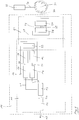
- the Fig. 1 shows a schematic representation of a first embodiment of a pump system 10.
- the pump system 10 comprises a pump unit 11, which is formed from a pump device 12 for conveying component material, a mixer 13, and a spray gun 14.
- a multi-component material mixed in the mixer 13 from the component materials can be sprayed or sprayed onto a surface with the spray gun 14, as is indicated here by the arrow 15.
- the pump device 12 in turn comprises a first pump 16 and a further pump 17 as well as a first liquid store 18 and a further liquid store 19 for receiving liquid component material in each case.
- the liquid stores 18 and 19 are each connected to the pumps 16 and 17 via media lines 20, the pumps 16 and 17 being connected to the mixer 13 via media lines 21, and this in turn being connected to the spray gun 14 via a media line 22.
- the pumps 16 and 17 are designed as pneumatically driven reciprocating piston pumps, so that component materials can be sucked in by the pumps 16 and 17 from the liquid stores 18 and 19 and conveyed under pressure via the media lines 21 to the mixer 13.
- the spray gun 14 has a compressed air connection, not shown here, so that the multicomponent material can be dispensed or sprayed using compressed air.
- the pump device 12 has an operating device 23, which can be used to control the pump devices 12 or the pump unit 11 in a simple manner.
- the operating device 23 provides an operator with basic functions for operating the pump device 12.
- the pump system 10 further comprises a control device 24 for controlling the operating device 23 or the pump device 12.
- the control device 24 forms a control unit 25 together with the operating device 23.
- the control device 24 itself has a control device 26 and a database 27.
- the control device 24 or the control device 26 is connected to the operating device 23 via a data connection 28 shown schematically here for data exchange.
- the control device 26 is also connected to the database 27 via a data connection 29 for data exchange.
- the control device 24 is connected to an external network 31, such as the Internet, via a data connection 30.
- Another database 33 is connected to the external network 31 via a data connection 32.
- the further database 33 is, for example, a database of the manufacturer of the pump system 10 or of the manufacturer of the component material.
- the control device 24 is preferably designed as a mobile phone, not shown here, so that the data connections 28 and 30 are wireless radio connections.
- the control device 26 thus represents a processor or data processing device of the mobile telephone and the database 27 a memory of the mobile telephone.
- the control device 24 has a functionality that is expanded compared to the operating device 23.
- the functionalities of the pump device 12 or the pump unit 11 can be used with the control device 24.
- data exchange between the operating device 23 and the control device 24 can also monitor the Pump device 12 or documentation of environmental parameters, operating states, operating parameters and / or error messages of the pump device 12 or pump unit 11 take place. This makes it possible for the data obtained to be used on the one hand for variable control of the pump device 12 by the control device 24 in the manner of a regulation, and on the other hand to use the documentation of the data for quality assurance and subsequent traceability of a work result.
- the database 27 contains recipes from manufacturers of component material, by means of which the control device 23 or the pump device 12 can be controlled.
- the control device 24 can then be used to set a mixing ratio of the pumps 16 and 17 by varying a delivery rate of the pumps 16 and 17 via the operating device 23.
- An on-site operator of the spray gun 14 is then no longer forced to resort directly to a recipe and to make the necessary settings on the pump device 12 or operating device 23.
- possible error messages from the pump device 12 can be transmitted to the control device 24, wherein the control device 24 can also forward these error messages to the external network 31.
- the recipes, documentation, manuals etc. can be kept in the further database 33 and can be synchronized at regular intervals with the data stored in the database 27.
- the Fig. 2 shows a second embodiment of a pump system 34, which differs from that in FIG Fig. 1 Pump system shown has a further pump device 35.
- the further pump device 35 has a first pump 36 and a further pump 37 as well as a first liquid store 38 and a further liquid store 39 and an operating device 40.
- the operating devices 23 and 40 now form a control unit 41 together with the control device 24.
- the further pump device 35 is also connected to the mixer 13 and the spray gun 14 via media lines 42 and 22.
- the control device 26 is wirelessly connected to the operating device 40 via a data connection 43.
- the pump device 12 and the pump device 35 are essentially identical, so that in the event of a failure of a pump device 12 or 35, the latter can be easily replaced without the pump unit 44 having to be taken out of operation completely. It is also possible to operate the pumps 16, 17 and 36, 37 completely independently of one another via the control device 24 and to interconnect them in any combination for mixing multicomponent material.
- the Fig. 3 shows a schematic representation of a third embodiment of a pump system 45.
- the pump system shown here has a pump unit 46 via a further mixer 47 and a further spray gun 48, the first pump 36 and the further pump 37 having media lines 49 the mixer 47, and the mixer 47 is connected to the spray gun 48 via a media line 50.
- the pump devices 12 and 35 can then also be used in a completely spatially separated manner, the control device 24 also being able to be set up spatially and spatially separately from the pump devices 12 and 35. Nevertheless, it is possible to control and monitor the pump devices 12 and 35 simultaneously.
- the Fig. 4 shows a schematic representation of an operating device 51 together with a control device 52.
- the control device 52 is designed as a mobile telephone 53 with a touch screen 54 and is coupled or connected to the operating device 51 via a radio data connection 55.
- the operating device 51 has a screen 56, a processor 57, a PLC control 58 and operating switches 59. These components are accommodated in a pressure-encapsulated housing 60 which corresponds to the ATEX standard.
- the operating switches 59 provide an operator with a restricted functionality of the pump unit (not shown here in more detail), wherein a full functionality of this pump unit can be used by means of the control device 52.
Landscapes
- Engineering & Computer Science (AREA)
- Mechanical Engineering (AREA)
- General Engineering & Computer Science (AREA)
- Computer Hardware Design (AREA)
- Physics & Mathematics (AREA)
- General Physics & Mathematics (AREA)
- Automation & Control Theory (AREA)
- Nozzles (AREA)
Claims (19)
- Procédé pour contrôler un système de pompe (10, 34, 45) ayant une unité de pompe (11, 44, 46) pour distribuer du matériau à composants multiples sous pression au moyen d'un pistolet pulvérisateur, l'unité de pompe comprenant un dispositif de pompe (12, 35), un mélangeur (13, 47) et un pistolet pulvérisateur (14, 48), le dispositif de pompe ayant au moins deux pompes (16, 17, 36, 37) pour refouler du matériau de composants et des réservoirs de liquide (18, 19, 38, 39) associés respectifs pour stocker du matériau de composants, le système de pompe ayant un dispositif de contrôle (24, 52), le dispositif de contrôle comprenant un moyen de contrôle (26) et une base de données (27),
caractérisé en ce que
des recettes pour mélanger des matériaux à composants multiples sont stockées dans la base de données, la base de données étant synchronisée avec au moins une autre base de données (33) externe à intervalles réguliers ou sur demande par le dispositif de contrôle, l'unité de pompe étant contrôlée au moyen du moyen de contrôle en fonction d'une recette. - Procédé selon la revendication 1,
caractérisé en ce que
le dispositif de pompe (12, 35) a un moyen de commande (23, 40, 51) au moyen duquel le dispositif de pompe (12, 35) est contrôlé, le dispositif de contrôle (24, 52) et le moyen de commande conjointement formant une unité de contrôle (25, 41) au moyen de laquelle l'unité de pompe (11, 44, 46) est contrôlée. - Procédé selon la revendication 2,
caractérisé en ce que
l'unité de contrôle (25, 41) stocke en continu des paramètres environnementaux, des états de fonctionnement, des paramètres de fonctionnement et/ou des messages d'erreur du dispositif de pompe (12, 35) pour une période de fonctionnement dans une base de données (27). - Procédé selon l'une quelconque des revendications précédentes,
caractérisé en ce que
le moyen de contrôle (26) trait des paramètres environnementaux, des états de fonctionnement, des paramètres de fonctionnement et/ou des messages d'erreur, le moyen de contrôle adaptant et changeant les recettes dans la base de données (27). - Procédé selon l'une quelconque des revendications précédentes,
caractérisé en ce que
des données sont échangées avec un réseau externe (31) au moyen du dispositif de contrôle (24, 52). - Procédé selon la revendication 5,
caractérisé en ce que
les recettes sont synchronisées avec des recettes des fabricants d'un matériau à composants multiples. - Procédé selon l'une quelconque des revendications précédentes,
caractérisé en ce que
le moyen de contrôle (26) reconnaît un type de pistolet pulvérisateur (14, 48), de mélangeur (13, 47) et/ou de moyen de pompe (12, 35), le moyen de contrôle corrigeant les recettes en tenant compte du type respectif. - Procédé selon l'une quelconque des revendications précédentes,
caractérisé en ce que
le moyen de contrôle (26) vérifie la plausibilité des paramètres environnementaux, des états de fonctionnement, des paramètres de fonctionnement et/ou des messages d'erreur en tenant compte des recettes. - Procédé selon l'une quelconque des revendications précédentes,
caractérisé en ce que
le moyen de commande (23, 40, 51) transmet des paramètres environnementaux, des états de fonctionnement, des paramètres de fonctionnement et/ou des messages d'erreur du dispositif de pompe (12, 35) au dispositif de contrôle (24, 52), le dispositif de contrôle traitant les paramètres environnementaux, les états de fonctionnement, les paramètres de fonctionnement et/ou les messages d'erreur. - Procédé selon l'une quelconque des revendications précédentes,
caractérisé en ce que
le pistolet pulvérisateur (14, 48) transmet des paramètres environnementaux, des états de fonctionnement, des paramètres de fonctionnement et/ou des messages d'erreur du pistolet pulvérisateur au dispositif de contrôle (24, 52), le moyen de contrôle (26) corrigeant les recettes en tenant compte des paramètres environnementaux respectifs, des états de fonctionnement respectifs, des paramètres de fonctionnement respectifs et/ou des messages d'erreur respectifs du pistolet pulvérisateur. - Procédé selon l'une quelconque des revendications précédentes,
caractérisé en ce que
des paramètres environnementaux, des états de fonctionnement, des paramètres de fonctionnement et/ou des messages d'erreur pour une période de fonctionnement sont stockés en continu par le dispositif de contrôle (24, 52). - Procédé selon l'une quelconque des revendications précédentes,
caractérisé en ce que
le dispositif de contrôle (24, 52) crée une documentation écrite des paramètres environnementaux, des états de fonctionnement, des paramètres de fonctionnement et/ou des messages d'erreur pour une période de fonctionnement. - Procédé selon l'une quelconque des revendications précédentes,
caractérisé en ce que
le moyen de commande (23, 40, 51) et/ou le dispositif de contrôle (24, 52) transmet(tent) des paramètres environnementaux, des états de fonctionnement, des paramètres de fonctionnement et/ou des messages d'erreur du dispositif de pompe (12, 35) au pistolet pulvérisateur (14, 48). - Procédé selon l'une quelconque des revendications précédentes,
caractérisé en ce que
des messages d'état du dispositif de contrôle (24, 52) sont transmis au moyen de commande (23, 40, 51) et/ou au pistolet pulvérisateur (14, 48) et sont affichés. - Procédé selon l'une quelconque des revendications précédentes,
caractérisé en ce
qu'une documentation du système de pompe (10, 34, 45) est fournie au moyen du dispositif de contrôle (24, 52). - Système de pompe (10, 34, 45) ayant une unité de pompe (11, 44, 46) pour distribuer du matériau à composants multiples sous pression au moyen d'un pistolet pulvérisateur, l'unité de pompe comprenant un dispositif de pompe (12, 35), un mélangeur (13, 47) et un pistolet pulvérisateur (14, 48), le dispositif de pompe ayant au moins deux pompes (16, 17, 36, 37) pour refouler du matériau de composants et des réservoirs de liquide (18, 19, 38, 39) associés respectifs pour stocker du matériau de composants, le système de pompe ayant un dispositif de contrôle (24, 52), le dispositif de contrôle comprenant un moyen de contrôle (26) pour contrôler l'unité de pompe et une base de données (27),
caractérisé en ce que
des recettes pour mélanger des matériaux à composants multiples sont stockées dans la base de données, la base de données étant synchronisable avec au moins une autre base de données (33) externe à intervalles réguliers ou sur demande par le dispositif de contrôle, l'unité de pompe étant contrôlable au moyen du moyen de contrôle en fonction d'une recette. - Système de pompe selon la revendication 16,
caractérisé en ce que
le dispositif de pompe (12, 35) a un moyen de commande (23, 40, 51) pour contrôler le dispositif de pompe, le dispositif de contrôle (24, 52) et le moyen de commande conjointement formant une unité de contrôle (25, 41) pour contrôler l'unité de pompe (11, 44, 46), l'unité de pompe étant contrôlable au moyen de l'unité de contrôle. - Système de pompe selon la revendication 16 ou 17,
caractérisé en ce que
le dispositif de contrôle (24, 52) est disposé à distance de l'unité de pompe (11, 44, 46). - Système de pompe selon l'une quelconque des revendications 16 à 18,
caractérisé en ce que
le dispositif de contrôle (24, 52) est configuré pour échanger des données avec un réseau externe (31).
Applications Claiming Priority (2)
| Application Number | Priority Date | Filing Date | Title |
|---|---|---|---|
| DE102014209159.4A DE102014209159A1 (de) | 2014-05-14 | 2014-05-14 | Verfahren zur Steuerung eines Pumpensystems sowie Pumpensystem |
| PCT/EP2015/056457 WO2015172931A1 (fr) | 2014-05-14 | 2015-03-25 | Procédé de commande d'un système de pompage et système de pompage |
Publications (2)
| Publication Number | Publication Date |
|---|---|
| EP3143281A1 EP3143281A1 (fr) | 2017-03-22 |
| EP3143281B1 true EP3143281B1 (fr) | 2020-06-24 |
Family
ID=52875111
Family Applications (1)
| Application Number | Title | Priority Date | Filing Date |
|---|---|---|---|
| EP15716443.5A Active EP3143281B1 (fr) | 2014-05-14 | 2015-03-25 | Procédé de fonctionnement d'un système de pompe et un système de pompe |
Country Status (6)
| Country | Link |
|---|---|
| US (1) | US20170152849A1 (fr) |
| EP (1) | EP3143281B1 (fr) |
| CN (1) | CN106460832A (fr) |
| DE (1) | DE102014209159A1 (fr) |
| ES (1) | ES2808628T3 (fr) |
| WO (1) | WO2015172931A1 (fr) |
Families Citing this family (10)
| Publication number | Priority date | Publication date | Assignee | Title |
|---|---|---|---|---|
| DE102014209157A1 (de) | 2014-05-14 | 2015-11-19 | Wiwa Wilhelm Wagner Gmbh & Co Kg | Verfahren zur Steuerung eines Pumpensystems sowie Pumpensystem |
| US10915198B2 (en) * | 2016-05-31 | 2021-02-09 | Clinicare Ltd. | Breast pump or other medical devices with dynamically adaptive pump configuration providing error detection and distinctive suction profile |
| DE102016117357A1 (de) * | 2016-09-15 | 2018-03-15 | Prominent Gmbh | Verfahren zum Betreiben von Dosiereinrichtungen |
| DE102017202604A1 (de) * | 2017-02-17 | 2018-08-23 | Putzmeister Mörtelmaschinen GmbH | Vorrichtung zur Mischung und Förderung von Dickstoffen |
| DE102017216812A1 (de) * | 2017-09-22 | 2019-03-28 | Wiwa Wilhelm Wagner Gmbh & Co. Kg | Verfahren zur Steuerung eines Pumpensystems sowie Pumpensystem |
| CN107876237A (zh) * | 2017-11-30 | 2018-04-06 | 北京东方雨虹防水技术股份有限公司 | 多组份材料喷涂设备 |
| WO2019237108A1 (fr) * | 2018-06-08 | 2019-12-12 | Fluid Handling Llc | Fonctionnement à rendement optimal dans un système de pompage parallèle avec apprentissage machine |
| JP2021026380A (ja) * | 2019-08-01 | 2021-02-22 | 東芝三菱電機産業システム株式会社 | プロセス制御装置 |
| DE202020105300U1 (de) | 2020-09-16 | 2021-12-21 | K.H. Brinkmann GmbH & Co Kommanditgesellschaft | Elektrische Pumpe |
| WO2026084988A1 (fr) * | 2024-10-14 | 2026-04-23 | Nordson Corporation | Plateformes modulaires et évolutives à venturi à poudre et à haute densité pour système de poudre |
Family Cites Families (17)
| Publication number | Priority date | Publication date | Assignee | Title |
|---|---|---|---|---|
| GB804836A (en) * | 1954-11-06 | 1958-11-26 | Bobard Emile | Improved multiple steering systems for vehicles |
| US4580721A (en) * | 1981-02-12 | 1986-04-08 | Imperial Chemical Industries Plc | Fluid container |
| US4529127A (en) * | 1983-04-25 | 1985-07-16 | The United States Of America As Represented By The United States Department Of Energy | Machine for applying a two component resin to a roadway surface |
| EP0420181A3 (en) * | 1989-09-27 | 1992-04-22 | Union Carbide Chemicals And Plastics Company, Inc. | Method and apparatus for metering and mixing noncompressible and compressible fluids |
| DE59101664D1 (de) * | 1990-10-05 | 1994-06-23 | Mgv Moest Spritzgeraete Prod | Vorrichtung zum Dosieren und Mischen von zwei flüssigen Komponenten. |
| DE19727622C1 (de) * | 1997-06-28 | 1998-10-22 | Hofmann Walter Maschf | Straßenmarkierungsmaschine mit fahrgeschwindigkeitsproportional angetriebener Pumpenkombination |
| US6379465B1 (en) * | 1999-09-17 | 2002-04-30 | Nordson Corporation | Coating system with centralized control panel and gun mapping |
| US6641666B2 (en) * | 1999-11-15 | 2003-11-04 | Ppg Industries Ohio, Inc. | Method and apparatus for coating a substrate |
| US6742718B2 (en) * | 2000-09-15 | 2004-06-01 | Electramist, Inc. | Electric rotary atomizing system for fluid applications |
| WO2003059521A2 (fr) * | 2002-01-15 | 2003-07-24 | Graco Minnesota Inc. | Protection anti-emballement pour pulverisateur |
| HK1062783A2 (en) * | 2004-05-10 | 2004-11-05 | 高立科技有限公司 | System and method for delivering reactive fluids to remote application sites |
| US8790517B2 (en) * | 2007-08-01 | 2014-07-29 | Rockwater Resource, LLC | Mobile station and methods for diagnosing and modeling site specific full-scale effluent treatment facility requirements |
| US9670919B2 (en) * | 2010-11-18 | 2017-06-06 | Wagner Spray Tech Corporation | Plural component pumping system |
| WO2013125671A1 (fr) * | 2012-02-23 | 2013-08-29 | 株式会社明治 | Système de mélange proportionnel |
| DE102012104214A1 (de) * | 2012-05-15 | 2013-11-21 | Xylem Ip Holdings Llc | Pumpaggregat, Pumpaggregat-Konfigurationssystem und Verfahren |
| DE102012010544B4 (de) * | 2012-05-29 | 2017-02-09 | J. Wagner Ag | Verfahren und Vorrichtung zum Mischen wenigstens zweier flüssiger Komponenten |
| DE102014209157A1 (de) * | 2014-05-14 | 2015-11-19 | Wiwa Wilhelm Wagner Gmbh & Co Kg | Verfahren zur Steuerung eines Pumpensystems sowie Pumpensystem |
-
2014
- 2014-05-14 DE DE102014209159.4A patent/DE102014209159A1/de not_active Withdrawn
-
2015
- 2015-03-25 EP EP15716443.5A patent/EP3143281B1/fr active Active
- 2015-03-25 ES ES15716443T patent/ES2808628T3/es active Active
- 2015-03-25 WO PCT/EP2015/056457 patent/WO2015172931A1/fr not_active Ceased
- 2015-03-25 US US15/310,391 patent/US20170152849A1/en not_active Abandoned
- 2015-03-25 CN CN201580035268.1A patent/CN106460832A/zh active Pending
Non-Patent Citations (1)
| Title |
|---|
| None * |
Also Published As
| Publication number | Publication date |
|---|---|
| ES2808628T3 (es) | 2021-03-01 |
| EP3143281A1 (fr) | 2017-03-22 |
| DE102014209159A1 (de) | 2015-11-19 |
| US20170152849A1 (en) | 2017-06-01 |
| WO2015172931A1 (fr) | 2015-11-19 |
| CN106460832A (zh) | 2017-02-22 |
Similar Documents
| Publication | Publication Date | Title |
|---|---|---|
| EP3143281B1 (fr) | Procédé de fonctionnement d'un système de pompe et un système de pompe | |
| EP3008530B1 (fr) | Procédé servant à paramétrer un appareil de terrain | |
| EP3143280B1 (fr) | Procédé de fonctionnement d'un système de pompe et un système de pompe | |
| EP2771747B1 (fr) | Procédé de lecture d'un code de modèle bidimensionnel et de représentation et utilisation de données, appareil portatif pour réaliser le procédé et procédé de réalisation d'un code de modèle bidimensionnel | |
| EP3460242B1 (fr) | Procédé de commande d'un système de pompe ainsi que système de pompe | |
| EP3143279B1 (fr) | Procédé de fonctionnement d'un système de pompe et un système de pompe | |
| WO2020227744A1 (fr) | Procédé de représentation et de commande de moyens de production, en particulier pour l'industrie de transformation des plastiques | |
| DE102006006273A1 (de) | System zur Ermittlung des Verschleißzustandes einer Werkzeugmaschine | |
| EP1862269B1 (fr) | Prodédé pour déterminer la quantité de laque nécessaire | |
| DE102016100241A1 (de) | Verfahren zum Herstellen eines Produkts mit integrierter Planung und direkter ganzheitlicher Steuerung | |
| EP2770382B1 (fr) | Procédé de mise en service d'un système d'automatisation | |
| EP3082001A1 (fr) | Procédé d'extension d'un dispositif d'automatisation avec un virtuel appareil d'automatisation et dispositif d'automatisation | |
| DE102018116892A1 (de) | Verfahren zum Parametrieren eines Sensorsystems | |
| DE102010033754B4 (de) | Fluidspeichermanagementsystem und Verfahren zur Überwachung von Fluidkapazitäten und zur Steuerung der Übertragung von Fluidkapazitäten innerhalb eines Fluidnetzes | |
| DE102013107993A1 (de) | Befüllmanagement für Pflanzenschutzmittel | |
| AT518965B1 (de) | Visualisierung einer Produktionsanordnung | |
| EP3729219A1 (fr) | Procédé de surveillance d'une station de mesure dans une installation d'automatisation de processus | |
| WO2022106358A1 (fr) | Réseau pour commander des systèmes de brasage et procédé associé | |
| DE202025103676U1 (de) | System zur prozesssicheren Herstellung von Rohrverbindungen | |
| DE202020005931U1 (de) | Netzwerk zur Steuerung von Lötsystemen | |
| DE102005013915A1 (de) | Verfahrenstechnische, insbesondere mikroverfahrenstechnische Anlage | |
| DE102017219187A1 (de) | System und Verfahren zur Konfiguration einer Schweissanlage | |
| DE102018132606A1 (de) | Verfahren zum Erstellen einer Favoritenliste im Rahmen des Parametrierens eines Feldgeräts der Automatisierungstechnik und Bedieneinheit | |
| EP3683637A1 (fr) | Procédé d'établissement d'une connexion bidirectionnelle entre un appareil, en particulier un appareil de terrain, et une application dans un dispositif centralisé | |
| DE102020105098A1 (de) | Verfahren zum Einstellen einer Applikationseinrichtung zum Applizieren eines Applikationsmaterials |
Legal Events
| Date | Code | Title | Description |
|---|---|---|---|
| STAA | Information on the status of an ep patent application or granted ep patent |
Free format text: STATUS: THE INTERNATIONAL PUBLICATION HAS BEEN MADE |
|
| PUAI | Public reference made under article 153(3) epc to a published international application that has entered the european phase |
Free format text: ORIGINAL CODE: 0009012 |
|
| STAA | Information on the status of an ep patent application or granted ep patent |
Free format text: STATUS: REQUEST FOR EXAMINATION WAS MADE |
|
| 17P | Request for examination filed |
Effective date: 20161212 |
|
| AK | Designated contracting states |
Kind code of ref document: A1 Designated state(s): AL AT BE BG CH CY CZ DE DK EE ES FI FR GB GR HR HU IE IS IT LI LT LU LV MC MK MT NL NO PL PT RO RS SE SI SK SM TR |
|
| AX | Request for extension of the european patent |
Extension state: BA ME |
|
| DAV | Request for validation of the european patent (deleted) | ||
| DAX | Request for extension of the european patent (deleted) | ||
| GRAP | Despatch of communication of intention to grant a patent |
Free format text: ORIGINAL CODE: EPIDOSNIGR1 |
|
| STAA | Information on the status of an ep patent application or granted ep patent |
Free format text: STATUS: GRANT OF PATENT IS INTENDED |
|
| INTG | Intention to grant announced |
Effective date: 20200123 |
|
| GRAS | Grant fee paid |
Free format text: ORIGINAL CODE: EPIDOSNIGR3 |
|
| GRAA | (expected) grant |
Free format text: ORIGINAL CODE: 0009210 |
|
| STAA | Information on the status of an ep patent application or granted ep patent |
Free format text: STATUS: THE PATENT HAS BEEN GRANTED |
|
| RAP1 | Party data changed (applicant data changed or rights of an application transferred) |
Owner name: WIWA WILHELM WAGNER GMBH & CO. KG |
|
| AK | Designated contracting states |
Kind code of ref document: B1 Designated state(s): AL AT BE BG CH CY CZ DE DK EE ES FI FR GB GR HR HU IE IS IT LI LT LU LV MC MK MT NL NO PL PT RO RS SE SI SK SM TR |
|
| REG | Reference to a national code |
Ref country code: GB Ref legal event code: FG4D Free format text: NOT ENGLISH |
|
| REG | Reference to a national code |
Ref country code: CH Ref legal event code: EP |
|
| REG | Reference to a national code |
Ref country code: AT Ref legal event code: REF Ref document number: 1284136 Country of ref document: AT Kind code of ref document: T Effective date: 20200715 |
|
| REG | Reference to a national code |
Ref country code: DE Ref legal event code: R096 Ref document number: 502015012861 Country of ref document: DE |
|
| REG | Reference to a national code |
Ref country code: IE Ref legal event code: FG4D Free format text: LANGUAGE OF EP DOCUMENT: GERMAN |
|
| REG | Reference to a national code |
Ref country code: CH Ref legal event code: NV Representative=s name: BODENSEEPATENT PATENTANWAELTE BEHRMANN WAGNER , CH |
|
| PG25 | Lapsed in a contracting state [announced via postgrant information from national office to epo] |
Ref country code: FI Free format text: LAPSE BECAUSE OF FAILURE TO SUBMIT A TRANSLATION OF THE DESCRIPTION OR TO PAY THE FEE WITHIN THE PRESCRIBED TIME-LIMIT Effective date: 20200624 Ref country code: LT Free format text: LAPSE BECAUSE OF FAILURE TO SUBMIT A TRANSLATION OF THE DESCRIPTION OR TO PAY THE FEE WITHIN THE PRESCRIBED TIME-LIMIT Effective date: 20200624 Ref country code: SE Free format text: LAPSE BECAUSE OF FAILURE TO SUBMIT A TRANSLATION OF THE DESCRIPTION OR TO PAY THE FEE WITHIN THE PRESCRIBED TIME-LIMIT Effective date: 20200624 Ref country code: NO Free format text: LAPSE BECAUSE OF FAILURE TO SUBMIT A TRANSLATION OF THE DESCRIPTION OR TO PAY THE FEE WITHIN THE PRESCRIBED TIME-LIMIT Effective date: 20200924 Ref country code: GR Free format text: LAPSE BECAUSE OF FAILURE TO SUBMIT A TRANSLATION OF THE DESCRIPTION OR TO PAY THE FEE WITHIN THE PRESCRIBED TIME-LIMIT Effective date: 20200925 |
|
| REG | Reference to a national code |
Ref country code: LT Ref legal event code: MG4D |
|
| PG25 | Lapsed in a contracting state [announced via postgrant information from national office to epo] |
Ref country code: BG Free format text: LAPSE BECAUSE OF FAILURE TO SUBMIT A TRANSLATION OF THE DESCRIPTION OR TO PAY THE FEE WITHIN THE PRESCRIBED TIME-LIMIT Effective date: 20200924 Ref country code: HR Free format text: LAPSE BECAUSE OF FAILURE TO SUBMIT A TRANSLATION OF THE DESCRIPTION OR TO PAY THE FEE WITHIN THE PRESCRIBED TIME-LIMIT Effective date: 20200624 Ref country code: RS Free format text: LAPSE BECAUSE OF FAILURE TO SUBMIT A TRANSLATION OF THE DESCRIPTION OR TO PAY THE FEE WITHIN THE PRESCRIBED TIME-LIMIT Effective date: 20200624 Ref country code: LV Free format text: LAPSE BECAUSE OF FAILURE TO SUBMIT A TRANSLATION OF THE DESCRIPTION OR TO PAY THE FEE WITHIN THE PRESCRIBED TIME-LIMIT Effective date: 20200624 |
|
| REG | Reference to a national code |
Ref country code: NL Ref legal event code: MP Effective date: 20200624 |
|
| PG25 | Lapsed in a contracting state [announced via postgrant information from national office to epo] |
Ref country code: AL Free format text: LAPSE BECAUSE OF FAILURE TO SUBMIT A TRANSLATION OF THE DESCRIPTION OR TO PAY THE FEE WITHIN THE PRESCRIBED TIME-LIMIT Effective date: 20200624 Ref country code: NL Free format text: LAPSE BECAUSE OF FAILURE TO SUBMIT A TRANSLATION OF THE DESCRIPTION OR TO PAY THE FEE WITHIN THE PRESCRIBED TIME-LIMIT Effective date: 20200624 |
|
| PG25 | Lapsed in a contracting state [announced via postgrant information from national office to epo] |
Ref country code: SM Free format text: LAPSE BECAUSE OF FAILURE TO SUBMIT A TRANSLATION OF THE DESCRIPTION OR TO PAY THE FEE WITHIN THE PRESCRIBED TIME-LIMIT Effective date: 20200624 Ref country code: EE Free format text: LAPSE BECAUSE OF FAILURE TO SUBMIT A TRANSLATION OF THE DESCRIPTION OR TO PAY THE FEE WITHIN THE PRESCRIBED TIME-LIMIT Effective date: 20200624 Ref country code: RO Free format text: LAPSE BECAUSE OF FAILURE TO SUBMIT A TRANSLATION OF THE DESCRIPTION OR TO PAY THE FEE WITHIN THE PRESCRIBED TIME-LIMIT Effective date: 20200624 Ref country code: IT Free format text: LAPSE BECAUSE OF FAILURE TO SUBMIT A TRANSLATION OF THE DESCRIPTION OR TO PAY THE FEE WITHIN THE PRESCRIBED TIME-LIMIT Effective date: 20200624 Ref country code: CZ Free format text: LAPSE BECAUSE OF FAILURE TO SUBMIT A TRANSLATION OF THE DESCRIPTION OR TO PAY THE FEE WITHIN THE PRESCRIBED TIME-LIMIT Effective date: 20200624 Ref country code: PT Free format text: LAPSE BECAUSE OF FAILURE TO SUBMIT A TRANSLATION OF THE DESCRIPTION OR TO PAY THE FEE WITHIN THE PRESCRIBED TIME-LIMIT Effective date: 20201026 |
|
| PG25 | Lapsed in a contracting state [announced via postgrant information from national office to epo] |
Ref country code: PL Free format text: LAPSE BECAUSE OF FAILURE TO SUBMIT A TRANSLATION OF THE DESCRIPTION OR TO PAY THE FEE WITHIN THE PRESCRIBED TIME-LIMIT Effective date: 20200624 Ref country code: SK Free format text: LAPSE BECAUSE OF FAILURE TO SUBMIT A TRANSLATION OF THE DESCRIPTION OR TO PAY THE FEE WITHIN THE PRESCRIBED TIME-LIMIT Effective date: 20200624 Ref country code: IS Free format text: LAPSE BECAUSE OF FAILURE TO SUBMIT A TRANSLATION OF THE DESCRIPTION OR TO PAY THE FEE WITHIN THE PRESCRIBED TIME-LIMIT Effective date: 20201024 |
|
| REG | Reference to a national code |
Ref country code: CH Ref legal event code: PFA Owner name: WIWA WILHELM WAGNER GMBH AND CO. KG, DE Free format text: FORMER OWNER: WIWA WILHELM WAGNER GMBH AND CO. KG, DE |
|
| REG | Reference to a national code |
Ref country code: ES Ref legal event code: FG2A Ref document number: 2808628 Country of ref document: ES Kind code of ref document: T3 Effective date: 20210301 |
|
| REG | Reference to a national code |
Ref country code: DE Ref legal event code: R097 Ref document number: 502015012861 Country of ref document: DE |
|
| PG25 | Lapsed in a contracting state [announced via postgrant information from national office to epo] |
Ref country code: DK Free format text: LAPSE BECAUSE OF FAILURE TO SUBMIT A TRANSLATION OF THE DESCRIPTION OR TO PAY THE FEE WITHIN THE PRESCRIBED TIME-LIMIT Effective date: 20200624 |
|
| PLBE | No opposition filed within time limit |
Free format text: ORIGINAL CODE: 0009261 |
|
| STAA | Information on the status of an ep patent application or granted ep patent |
Free format text: STATUS: NO OPPOSITION FILED WITHIN TIME LIMIT |
|
| PGFP | Annual fee paid to national office [announced via postgrant information from national office to epo] |
Ref country code: AT Payment date: 20210318 Year of fee payment: 7 |
|
| 26N | No opposition filed |
Effective date: 20210325 |
|
| PG25 | Lapsed in a contracting state [announced via postgrant information from national office to epo] |
Ref country code: SI Free format text: LAPSE BECAUSE OF FAILURE TO SUBMIT A TRANSLATION OF THE DESCRIPTION OR TO PAY THE FEE WITHIN THE PRESCRIBED TIME-LIMIT Effective date: 20200624 |
|
| PG25 | Lapsed in a contracting state [announced via postgrant information from national office to epo] |
Ref country code: MC Free format text: LAPSE BECAUSE OF FAILURE TO SUBMIT A TRANSLATION OF THE DESCRIPTION OR TO PAY THE FEE WITHIN THE PRESCRIBED TIME-LIMIT Effective date: 20200624 |
|
| PG25 | Lapsed in a contracting state [announced via postgrant information from national office to epo] |
Ref country code: IE Free format text: LAPSE BECAUSE OF NON-PAYMENT OF DUE FEES Effective date: 20210325 Ref country code: LU Free format text: LAPSE BECAUSE OF NON-PAYMENT OF DUE FEES Effective date: 20210325 |
|
| REG | Reference to a national code |
Ref country code: AT Ref legal event code: MM01 Ref document number: 1284136 Country of ref document: AT Kind code of ref document: T Effective date: 20220325 |
|
| PG25 | Lapsed in a contracting state [announced via postgrant information from national office to epo] |
Ref country code: AT Free format text: LAPSE BECAUSE OF NON-PAYMENT OF DUE FEES Effective date: 20220325 |
|
| PG25 | Lapsed in a contracting state [announced via postgrant information from national office to epo] |
Ref country code: HU Free format text: LAPSE BECAUSE OF FAILURE TO SUBMIT A TRANSLATION OF THE DESCRIPTION OR TO PAY THE FEE WITHIN THE PRESCRIBED TIME-LIMIT; INVALID AB INITIO Effective date: 20150325 |
|
| P01 | Opt-out of the competence of the unified patent court (upc) registered |
Effective date: 20230524 |
|
| PG25 | Lapsed in a contracting state [announced via postgrant information from national office to epo] |
Ref country code: CY Free format text: LAPSE BECAUSE OF FAILURE TO SUBMIT A TRANSLATION OF THE DESCRIPTION OR TO PAY THE FEE WITHIN THE PRESCRIBED TIME-LIMIT Effective date: 20200624 |
|
| PG25 | Lapsed in a contracting state [announced via postgrant information from national office to epo] |
Ref country code: MK Free format text: LAPSE BECAUSE OF FAILURE TO SUBMIT A TRANSLATION OF THE DESCRIPTION OR TO PAY THE FEE WITHIN THE PRESCRIBED TIME-LIMIT Effective date: 20200624 |
|
| PG25 | Lapsed in a contracting state [announced via postgrant information from national office to epo] |
Ref country code: TR Free format text: LAPSE BECAUSE OF FAILURE TO SUBMIT A TRANSLATION OF THE DESCRIPTION OR TO PAY THE FEE WITHIN THE PRESCRIBED TIME-LIMIT Effective date: 20200624 |
|
| PG25 | Lapsed in a contracting state [announced via postgrant information from national office to epo] |
Ref country code: MT Free format text: LAPSE BECAUSE OF FAILURE TO SUBMIT A TRANSLATION OF THE DESCRIPTION OR TO PAY THE FEE WITHIN THE PRESCRIBED TIME-LIMIT Effective date: 20200624 |
|
| PGFP | Annual fee paid to national office [announced via postgrant information from national office to epo] |
Ref country code: DE Payment date: 20250515 Year of fee payment: 11 |
|
| PGFP | Annual fee paid to national office [announced via postgrant information from national office to epo] |
Ref country code: ES Payment date: 20250416 Year of fee payment: 11 |
|
| PGFP | Annual fee paid to national office [announced via postgrant information from national office to epo] |
Ref country code: CH Payment date: 20250401 Year of fee payment: 11 |
|
| REG | Reference to a national code |
Ref country code: CH Ref legal event code: U11 Free format text: ST27 STATUS EVENT CODE: U-0-0-U10-U11 (AS PROVIDED BY THE NATIONAL OFFICE) Effective date: 20260401 |
|
| PGFP | Annual fee paid to national office [announced via postgrant information from national office to epo] |
Ref country code: GB Payment date: 20260324 Year of fee payment: 12 |
|
| PGFP | Annual fee paid to national office [announced via postgrant information from national office to epo] |
Ref country code: BE Payment date: 20260323 Year of fee payment: 12 |
|
| PGFP | Annual fee paid to national office [announced via postgrant information from national office to epo] |
Ref country code: FR Payment date: 20260324 Year of fee payment: 12 |