EP3143312B1 - Dispositif d'actionnement d'un frein de stationnement d'une transmission de véhicule automobile - Google Patents
Dispositif d'actionnement d'un frein de stationnement d'une transmission de véhicule automobile Download PDFInfo
- Publication number
- EP3143312B1 EP3143312B1 EP15718892.1A EP15718892A EP3143312B1 EP 3143312 B1 EP3143312 B1 EP 3143312B1 EP 15718892 A EP15718892 A EP 15718892A EP 3143312 B1 EP3143312 B1 EP 3143312B1
- Authority
- EP
- European Patent Office
- Prior art keywords
- actuator
- cable
- parking lock
- lever
- control cable
- Prior art date
- Legal status (The legal status is an assumption and is not a legal conclusion. Google has not performed a legal analysis and makes no representation as to the accuracy of the status listed.)
- Not-in-force
Links
- 230000005540 biological transmission Effects 0.000 title claims description 25
- 230000007246 mechanism Effects 0.000 claims description 6
- 230000006835 compression Effects 0.000 claims description 5
- 238000007906 compression Methods 0.000 claims description 5
- 238000009434 installation Methods 0.000 description 6
- 230000008859 change Effects 0.000 description 5
- 238000010276 construction Methods 0.000 description 4
- 230000005294 ferromagnetic effect Effects 0.000 description 3
- 230000010354 integration Effects 0.000 description 3
- 230000007935 neutral effect Effects 0.000 description 3
- 230000004913 activation Effects 0.000 description 2
- 230000008901 benefit Effects 0.000 description 2
- 238000005096 rolling process Methods 0.000 description 2
- 238000004904 shortening Methods 0.000 description 2
- 229910000831 Steel Inorganic materials 0.000 description 1
- 230000009471 action Effects 0.000 description 1
- 230000003213 activating effect Effects 0.000 description 1
- 230000008878 coupling Effects 0.000 description 1
- 238000010168 coupling process Methods 0.000 description 1
- 238000005859 coupling reaction Methods 0.000 description 1
- 230000001419 dependent effect Effects 0.000 description 1
- 238000006073 displacement reaction Methods 0.000 description 1
- KJFBVJALEQWJBS-XUXIUFHCSA-N maribavir Chemical compound CC(C)NC1=NC2=CC(Cl)=C(Cl)C=C2N1[C@H]1O[C@@H](CO)[C@H](O)[C@@H]1O KJFBVJALEQWJBS-XUXIUFHCSA-N 0.000 description 1
- 238000000034 method Methods 0.000 description 1
- 210000002445 nipple Anatomy 0.000 description 1
- 210000001331 nose Anatomy 0.000 description 1
- 230000002093 peripheral effect Effects 0.000 description 1
- 230000036316 preload Effects 0.000 description 1
- 230000008569 process Effects 0.000 description 1
- 239000010959 steel Substances 0.000 description 1
Images




Classifications
-
- F—MECHANICAL ENGINEERING; LIGHTING; HEATING; WEAPONS; BLASTING
- F16—ENGINEERING ELEMENTS AND UNITS; GENERAL MEASURES FOR PRODUCING AND MAINTAINING EFFECTIVE FUNCTIONING OF MACHINES OR INSTALLATIONS; THERMAL INSULATION IN GENERAL
- F16H—GEARING
- F16H63/00—Control outputs from the control unit to change-speed- or reversing-gearings for conveying rotary motion or to other devices than the final output mechanism
- F16H63/02—Final output mechanisms therefor; Actuating means for the final output mechanisms
- F16H63/30—Constructional features of the final output mechanisms
- F16H63/34—Locking or disabling mechanisms
- F16H63/3416—Parking lock mechanisms or brakes in the transmission
- F16H63/3491—Emergency release or engagement of parking locks or brakes
-
- F—MECHANICAL ENGINEERING; LIGHTING; HEATING; WEAPONS; BLASTING
- F16—ENGINEERING ELEMENTS AND UNITS; GENERAL MEASURES FOR PRODUCING AND MAINTAINING EFFECTIVE FUNCTIONING OF MACHINES OR INSTALLATIONS; THERMAL INSULATION IN GENERAL
- F16H—GEARING
- F16H61/00—Control functions within control units of change-speed- or reversing-gearings for conveying rotary motion ; Control of exclusively fluid gearing, friction gearing, gearings with endless flexible members or other particular types of gearing
- F16H61/26—Generation or transmission of movements for final actuating mechanisms
- F16H61/36—Generation or transmission of movements for final actuating mechanisms with at least one movement being transmitted by a cable
Definitions
- the invention relates to a device for actuating a parking lock of a motor vehicle transmission.
- shift by wire circuits For example so-called “shift by wire circuits”.
- shift lever when the shift lever is in the "P" position, the parking lock in the transmission is engaged accordingly with the help of an electric motor in particular.
- To deploy the parking lock very high forces must often be applied, for example when parking the motor vehicle on a steep incline. Therefore, such "shift by wire concepts" have a greater construction effort and are correspondingly costly, in particular because high demands are placed on functional safety and an emergency release must be provided in an emergency, especially if there is a power failure and the parking lock is through an electric motor has already been inserted.
- a device for actuating a parking lock where if the motor vehicle breaks down, the parking lock is automatically activated for safety reasons, that is, it can be brought into the activated position in order to also safely prevent the vehicle from rolling away. Nevertheless, it should also be possible to release this parking lock if necessary, that is to say it should be able to be brought into the deactivated position, namely in order to enable the vehicle to be towed. At the time of a power failure, the parking lock is initially in the deactivated position.
- a holding actuator is provided, with a lever actuator provided here in the holding actuator being opened due to a spring after the voltage has ceased, that is to say in the de-energized state, and a nipple of the cable pull is released as a result. Another provided return spring then moves the now free Bowden cable in the direction of the transmission, whereby the parking lock is activated, that is, brought into the activated position and thus inserted accordingly. The broken-down motor vehicle is then secured against rolling away.
- the aforementioned holding actuator is arranged here between the end of the Bowden cable and a further actuator which normally actuates the Bowden cable accordingly in order to engage or disengage the parking lock.
- the holding actuator arranged between the cable (Bowden cable) and the actuator therefore establishes a mechanical connection between the end of the Bowden cable and the actuator (main actuator).
- an actuating device consisting of an actuator (main actuator) and a holding actuator is provided, which actuates the Bowden cable (cable) or the parking lock accordingly.
- a device for actuating a parking lock of a motor vehicle is known, the parking lock being able to be engaged or disengaged via an actuator, but manual emergency unlocking via the core of a Bowden cable.
- the DE 10 2008 000 857 A1 shows a device with the help of which a locking element in the automatic transmission can be designed.
- the device has a cable element.
- a toggle lever can be pivoted via an actuator, with the aid of which the cable pull element can then be brought into an " overtravel position".
- the design of the toggle lever and the operating lever and the arrangement of the actuator is complex and space-consuming.
- a parking brake pedal is releasable, namely via the second cable element, with a control lever or a locking element being actuatable via the first cable element.
- the release lever and a cam element that is functionally effectively coupled to it have a control cam via which a parking brake or the parking brake pedal can be deactivated.
- the two cable elements are not directly connected to one another.
- the invention is therefore based on the object of designing and developing the aforementioned device, from which the invention is based, in such a way that the required installation space is small, and in particular the aforementioned disadvantages are avoided.
- the parking lock can now be brought into the activated position or into the deactivated position; for this purpose, at least one actuator is now provided. It is crucial that the cable pull or the cable pull system now has a sub-area and a connecting element that can be actuated by the actuator is functionally arranged and / or integrated within this sub-area so that the effective cable length can be changed when the actuator is actuated accordingly and is then Ultimately, the parking lock can be activated or deactivated. In particular, when the actuator is actuated in its active state, the effective cable length can be extended, which may be explained in detail below.
- the parking lock is therefore preferably activated, in particular engaged, in the passive state of the actuator, the parking lock being deactivated, in particular designed, in particular in the active state of the actuator.
- the kinematic reversal is also an alternative - conceivable. It is therefore conceivable that in the active state of the actuator the Parking lock activated, in particular engaged, with the parking lock being deactivated, that is to say designed, in particular in the passive state of the actuator.
- the preferred embodiment is the first alternative mentioned above.
- the actuator and / or the connecting element is now preferably designed in such a way that, in the active state of the actuator, the effective cable length - compared with a passive actuator - is correspondingly lengthened. But here too a kinematic reversal is accordingly conceivable. It is conceivable that in the passive state of the actuator the effective cable length - compared with the active actuator - is correspondingly lengthened, that is, the active actuator in its then active state shortens the cable length, but the above-mentioned first alternative is the preferred embodiment.
- the actuator is preferably designed as an electrically and / or magnetically actuated piston-cylinder unit, but also other designs, in particular also differently designed piston-cylinder units, which for example have a hinge and / or gear worm drive or can also be pneumatically or hydraulically actuated, are conceivable.
- a connecting element can be arranged directly in the aforementioned sub-area of the cable pull or can be effectively integrated there, the actuator being arranged fixed to the vehicle, but being functionally connected to the connecting element.
- the connecting element has a lever actuator which can be actuated via the actuator, as well as further components which may be explained below.
- one end of the cable in particular a first cable element
- another end of the cable in particular a second cable element
- the cable pull then has two cable pull elements or the cable pull then consists of two cable pull elements.
- a rod element is provided on the one hand between the gearshift lever and the actuator or the connecting element and on the other hand a cable element is provided between the actuator or the connecting element and the parking lock.
- the cable consists of only one Cable element, the partial area being formed at the end of this cable element and being connected to the gearshift lever via the rod element.
- the above-mentioned sub-area can therefore in principle also be formed at the end of a cable pull or at the end of a cable pull element, so that the cable pull then "includes" this sub-area in the end.
- a rod element is provided between the actuator or the connecting element and the parking lock (or the actuating device of the parking lock) and, in particular, a cable element is provided between the actuator or the connecting element and the gearshift lever, in particular the aforementioned sub-area is again formed at the end of the cable element, as mentioned above, and is connected to the parking lock via the rod element.
- a rod element can also be provided between the actuator or the connecting element and the shift selector lever. It is therefore conceivable that the cable pull or the corresponding cable pull elements are, in particular, rod-shaped or rod-like or designed as rod elements.
- a rod-shaped cable element or a cable element designed as a rod element can be provided or arranged between the gearshift lever and the actuator or the connecting element and / or between the actuator or connecting element and the parking lock.
- Vzw. is the cable or the cable elements are designed as steel cables or so-called Bowden cables.
- the Figures 3 to 15 show, at least partially, a device 1 for actuating a parking lock 2 of a motor vehicle transmission, in particular an automatic, in particular automated, manual transmission not shown here in detail, of a motor vehicle also not shown in detail here.
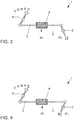
- At least one cable 3 is provided, with the help of the cable 3 the parking lock 2 in the activated position "P1", as for example Fig. 3 shown, or in the deactivated position "P0", as for example Fig. 4 shown is displaceable.
- at least one actuator 4 is provided, which is in the Fig. 3, 4 , 5a and 5b , as well as in the Figures 10, 11 , 12a and 12b is shown schematically.
- the cable 3 has a certain sub-area 3a, with a connecting element 5 operable by the actuator 4 being functionally arranged and / or integrated within the sub-area 3a so that when the actuator 4 is actuated accordingly, the effective cable length can be changed and thereby ultimately the Parking lock 2 can be activated or deactivated.
- the aforementioned sub-area 3a is formed or provided within the area of the cable 3. In other words, the cable 3 has the connecting element 5.
- the actuator 4 is functionally arranged and / or integrated within the sub-area 3a of the cable 3 so that when the actuator 4 is actuated accordingly, the effective cable length can be changed, in particular extended, and thereby the parking lock preferably can be deactivated.
- the actuator 4 is preferably not fixed to the vehicle, but in particular is arranged to be movable, which will be explained in more detail below.
- an in particular mechanical connecting element 5 is arranged and / or integrated in this sub-area 3a within the sub-area 3a of the cable 3 so that the effective cable length of the cable 3 can then be changed, in particular extended, when the actuator 4 is actuated accordingly, in order to thereby preferably deactivate the parking lock 2.
- the actuator 4 is preferably arranged fixed to the vehicle and actuates (or controls) the corresponding connection element 5 arranged within the sub-area 3a.
- the second embodiment according to the invention is particularly shown in FIG Figs. 10-15 shown schematically.
- the Fig. 4 shows the actuator 4 in a schematic representation in the active state, preferably in the energized state.
- the gearshift lever 6 is - as before - in the "P" position.
- the actuator 4 is in the active state, i.e. has been activated, the effective cable length of the cable 3 is now lengthened, as shown schematically and can be seen, so that the parking lock 2 is designed in the transmission, i.e. in the deactivated position "P0" has been or will be spent.
- the Figures 5a and 5b clearly show that in the event that the actuator 4 is in the passive state, in particular in the de-energized state, the effective cable length of the cable 3 does not change.
- the actuator 4 is arranged or integrated in the sub-area 3a of the cable control 3 so that when the shift lever 6 is moved from the "P" (parking) position, as in FIG Figure 5a shown in the in Figure 5b position shown, so when the shift lever 6 is moved to the "N" position (neutral position) to be in the in Figure 5b
- the actuator 4 moves accordingly with the cable 3.
- the actuator 4 provided it is in the passive state, that is to say the “passive actuator 4”, does not change the effective cable length of the cable 3.
- FIG. 6 shows the structural / constructive design of the actuator 4 or the piston-cylinder unit 4a.
- the cylindrical housing 7 and the piston 8 or the piston rod 8a which are movably or displaceably arranged in the housing can be clearly seen here.
- a permanent magnet 9 is provided or formed at one end of the wall of the housing 7, a return spring 10 being arranged between the piston 8 and the other wall of the housing 7.
- the inner wall of the housing 7 has a ferromagnetic sleeve 20 to implement an electromagnetic force.
- An electrical coil 11 is provided or arranged on the peripheral wall of the housing 7.
- Im energized State we magnetized the ferromagnetic sleeve 20 and thereby pulls the piston 8 to the right.
- the piston 8 In the passive state of the actuator 4, that is to say in the de-energized state, the piston 8 is pressed with the return spring 10 against the left wall of the housing 7, as in FIG Fig. 6 shown.
- the activated, i.e. active, state of the actuator 4 especially in the energized state, the piston 8 is then shifted and changed accordingly to the right within the housing 7 against the compressive force of the return spring 10 due to the electromagnetic forces, in particular thus extending the effective cable length of the cable 3.
- a partial area of the cable 3 is effectively connected on the left side to the wall of the housing 7 and the other part of the cable 3 is effectively connected to the right end of the piston rod 8a, as in FIG Fig. 6 visible and shown.
- FIG. 12 therefore shows the embodiment of an electromagnetically operated actuator 4.
- the statements made above for the actuator 4 essentially also apply to the second embodiment of the device 1, which is shown in FIGS Figs. 10-15 is shown, so in particular for the Figs. 10-15 shown actuator 4 of the second embodiment of the device 1.
- the actuator 4 in the Figures 3 to 9 is not arranged fixed to the vehicle, but is arranged movable to the vehicle, namely is essentially completely integrated within the sub-area 3a of the cable 3. It is also conceivable that, as in Fig. 6 shown, the actuator 4 is movably guided on the bar 12 via guide webs 13 arranged on a bar 12. In contrast, the one in the Figs. 10-15 Actuator 4 shown stationary, ie arranged fixed to the vehicle, which will be explained in more detail below.
- Figures 7 to 9 in a schematic representation of the integration of the actuator 4 in the cable 3 or in a certain sub-area 3a of the cable 3.
- One end of the cable 3 is connected to the shift lever 6, in the Figures 7 to 9 not shown, connected and the other end of the cable 3 is operatively connected to the parking lock 2 or to an actuating mechanism of the parking lock 2, also in the Figures 7 to 9 not shown.
- the parking lock 2 or its actuation mechanism is preferably spring-loaded in the direction of the activated position, that is, in the direction of engaging the parking lock 2 (the latter also applies to the preferred embodiment shown in FIGS Figs. 10-15 is shown).
- the shift lever 6 or the parking lock 2 is in the Figures 7 to 9 not explicitly shown, but the positions of the cable 3 or of the actuator 4 with the corresponding positioning of the shift lever 6 are shown in a schematic representation by corresponding dash-dotted lines. Just as it is also shown schematically, whether the parking lock 2 of the transmission is inserted or designed for certain positions or with passive or active actuator 4, likewise shown by corresponding dotted lines.
- the gear selector lever 6 is in the "N" position, in which Fig. 8 in the "P" position and in the Fig. 9 also in the "P" position.
- the actuator 4 shown here (as in Fig. 6 shown) preferably also movably arranged on the vehicle, namely in particular via the guide webs movably arranged on a bar, however, in Fig. 7 the actuator 4 is de-energized here, that is to say in the passive state, so that the parking lock 2 is designed or is in the deactivated position.
- the piston 8 is pressed against the left wall of the housing 7, so that the effective cable length of the cable 3 - compared to the activated state of the actuator 4 - is correspondingly shortened.
- the shift lever is moved to the "P" (Park) position.
- the actuator 4 When the actuator 4 is not active, that is to say when the actuator 4 is in the passive state, the entire actuator 4 or the respective piston-cylinder unit 4a moves into the position shown in FIG Fig. 8 position shown on the left.
- the cable 3 is also shifted or pulled from right to left, so that the parking lock 2, as in FIG Fig. 8 shown, is moved from the deactivated position "P0" to the activated position "P1", that is, it is now inserted or is inserted.
- Fig. 9 now shows the activation of the actuator 4, that is to say the actuator 4 in the activated state with the shift lever 6 in the "P" position, as also in FIG Fig. 8 shown. But now in Fig. 9 the effective cable length of cable 3 is extended accordingly, in particular because the actuator 4 is supplied with current accordingly. As a result, the piston 8 is moved within the housing 7 from left to right against the compressive force of a return spring, not shown, so that the effective cable length of the cable 3 is increased, namely the right area of the cable 3 is moved from left to right, so that the Parking lock 2 is brought into its deactivated state "P0", namely the parking lock 2 is disengaged in the transmission, even when the shift lever 6 is in the "P" position.
- the actuator 4 in particular as a piston-cylinder unit 4a.
- the piston-cylinder unit 4a preferably has a return spring 10 and a permanent magnet 9 and a coil 11 here.
- the actuator 4 is designed as a piston-cylinder unit, the piston then being actuatable via a stepping motor, a hinge and / or a gear worm drive, or also pneumatically or hydraulically. The latter is dependent on the specific design of the respective actuator 4.
- the aforementioned alternatives for other embodiments of the actuator 4 also apply in principle to those in FIG Figs. 10-15 Second embodiment of the device 1 according to the invention shown
- FIGs. 10-15 now show the preferred embodiment according to the invention for the device 1:
- the Figures 10, 11 , 12a and 12b first of all that the connecting element 5 is arranged directly in the sub-area 3a of the cable 3 or is effectively integrated into the cable 3 here.
- the connecting element 5 is preferably designed purely mechanically, with the second in the Figs. 10-15
- the actuator 4 now - in contrast to that in the Figures 3 to 9 illustrated embodiment - is arranged fixed to the vehicle.
- the actuator 4 is now functionally effectively connected to the aforementioned connecting element 5 or can act accordingly on the connecting element 5.
- the latter is in the Figures 10 and 11 initially shown schematically.
- Fig. 10 the actuator 4 in the passive state, whereby it can be clearly seen that the connecting element 5 is integrated directly into the sub-area 3a of the cable 3 and / or is attached here.
- the gearshift lever 6 is in the "P" (park) position, with how the Fig. 10 shows that the parking lock 2 is engaged in the transmission, that is, in its activated position "P1".
- the actuator 4 is activated, that is to say is in the active state, in particular is energized, it acts on the mechanical connecting element 5, preferably correspondingly, or actuates it.
- the connecting element 5 is designed so that the effective cable length of the cable 3 can then be correspondingly lengthened, which should be represented by the "gap" that can be seen in the box of the connecting element 5. Due to the change in the effective cable length of the cable 3, although the gear selector lever 6 is in the "P" (parking) position - as in FIG Fig. 11 shown - is, the parking lock 2 is then disengaged, that is, brought into its deactivated position "P0".
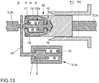
- the Figs. 13-15 now show the actuator 4, which is designed here in particular as an electromagnetically actuatable piston-cylinder unit 4a, in a schematic representation, but it is shown here in FIGS Figs. 13-15 Actuator 4 shown arranged stationary, in particular mounted fixed to the vehicle at a certain position. In the cable 3, namely in the sub-area 3a of the cable 3 integrated or arranged, however, the mechanical connecting element 5 is here.
- the connecting element 5, like the Figs. 13-15 show a lever actuator system 14 which can be actuated via the actuator 4, a sleeve 15 with a recess 15a and a piston element 16 guided in the recess 15a.
- a compression spring 17 is provided between the piston element 16 and an end wall of the sleeve 15.
- the piston element 16 is fixed in a certain position via the lever actuator system 14 when the actuator 4 is in a passive state.
- a part of the cable 3 is arranged on the piston element 16 or is effectively connected to it, the other part of the cable 3 being fastened or effectively coupled to the end wall of the sleeve 15 opposite the piston element 16.
- the piston element 16 is positively locked or unlocked accordingly via the lever actuator system 14, in particular the lever actuator system 14 has corresponding lever arms, not shown in detail, with noses that engage in corresponding recesses of the piston element 16, which are not shown here.
- the actuator 4 can come into operative connection via an adjusting lever 18 with the lever actuator 14 or the left end wall of the sleeve 15, as in particular in FIG Fig. 15 shown, namely preferably when the actuator 4 is brought into the active state or is activated, in particular is energized.
- Fig. 13 shows the gear selector lever 6 in the "P" position and the actuator 4 in its passive state.
- the actuator 4 is preferably designed as an electrically, magnetically actuatable piston-cylinder unit 4a, as essentially explained above, but attached to the vehicle in a stationary manner.
- the lever actuator system 14 of the mechanical connecting element 5 is not actuated, so that the piston element 16 is correspondingly locked with the aid of the lever actuator system 14. Therefore, when the shift lever is actuated accordingly, the cable 3 is in the "P" position, as in FIG Fig. 13 shown, shifted accordingly, so that the parking lock 2 is brought into the activated position "P1", that is, the parking lock 2 is engaged accordingly in the transmission or is then engaged, as in FIG Fig. 13 shown.
- Fig. 14 now also shows the actuator 4 in the passive, ie not activated, state, but for the gearshift lever in the "D" (Drive) position.
- the passive actuator 4 the lever actuator 14 of the connecting element 5 does not operate, that is, the lever actuator 14 locks the piston element 16 in a correspondingly form-fitting manner, that is, the cable length of the cable 3 is not changed. Therefore, when the gear selector lever is in position "D", the cable 3 is shifted essentially from left to right (compared to FIG Fig. 13 ), so that the parking lock 2 is then disengaged in the transmission, so in particular is brought into its deactivated position "P0".
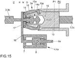
- Fig. 15 now shows an activation of the actuator 4, that is to say the actuator 4 in the active state, in particular in the energized state.
- the gearshift lever is in position "P"
- the adjusting lever 18 is moved from the left (as in Fig. 13 shown) to the right, as now in Fig. 15 shown, moved.
- the adjusting lever 18 actuates the lever actuator 14 so that the corresponding lever elements are pivoted outward so that the piston element 16 is unlocked.
- the adjusting lever 18 acts on the left end wall of the sleeve 15 and moves it against the spring force of the compression spring 17, so that the piston element 16 is moved within the recess 15a to the left and against the spring force of the compression spring 17 or moves to the left.
- This extends the effective cable length of the cable 3, so that then - in the end - the parking lock 2 is disengaged in the transmission, that is, moved from the activated position "P1" to the deactivated position "P0", as in FIG
- Fig. 15 shown.
- the active actuator 4 therefore actuates the lever actuator system 14 via the adjusting lever 18 to unlock the piston element 16, the adjusting lever 18 also being able to be brought into contact with the end wall of the sleeve 15 in order to realize the corresponding displacement.
- the guide sleeve 19 has beveled guide surfaces 19a at one end.
- the guide sleeve 19, in particular the beveled guide surfaces 19a and the lever actuator system 14, in particular the guide surfaces 14a provided here, on the one hand interact in such a way that the lever actuator system 14 is closed when the cable 3 is moved to the right.
- the sleeve 15, the lever actuator 14 and the guide sleeve 19 are especially designed and designed so that when the shift lever 6 is outside the "P" position, the lever actuator 14 cannot be unlocked, i.e. it is always in the closed, locked position.
- the actuator 4 is fixedly attached, in particular fixed to the vehicle, at a certain position, it interacts with the connecting element 5 in such a way that, when the actuator 4 is active, the effective cable length of the cable 3 is increased, in particular by the Park lock 2, even if the gearshift lever is in position "P", to be interpreted, that is, to spend in the deactivated position "P0".
- actuator 4 As mentioned above, namely through the implementation of the drive for the piston or for the piston element via a stepper motor, a hinge and / or gear worm drive or also pneumatically or hydraulically, depending on the embodiment.
- the ones in the Figures 6 to 9 or in the Figs. 13-15 have a cable 3 which has two cable elements 3b and 3c; in particular, the cable 3 consists of the two cable elements 3b and 3c.
- the left cable element 3b shown here is connected on the one hand to the shift lever 6, on the other hand to the sleeve 7 of the actuator 4 there, the cable element 3c shown on the right with the piston rod 8a of the actuator 4 on the one hand and with the parking lock 2 on the other connected is.
- the sub-area 3a is thus arranged or formed between the two cable pull elements 3b and 3c.
- the actuator 4 connects the two cable elements 3b and 3c here.
- the cable 3 also has two cable elements 3b and 3c. That in the Figs. 13-15 Cable element 3b shown on the left is connected on the one hand to the selector lever 6 and on the other hand to the piston rod of the piston element 16, not designated here, the other - in the Figs. 13-15 Cable element 3c shown on the right is connected on the one hand to the sleeve 15 and on the other hand to the parking lock 2.
- the sub-area 3a is also arranged and formed here between the two cable pull elements 3b and 3c.
- the connecting element 5 is therefore arranged or provided in the sub-area 3a or connects the two cable pull elements 3b and 3c.
- the cable 3 has the two cable elements 3b and 3c or consists of these cable elements 3b and 3c.
- the Figures 3 to 15 therefore show the basic principle of designing the parking lock 2, i.e. deactivating the parking lock 2 by extending the cable 3.
- the "reverse solution” is also a shortening of the cable length of the cable 3, especially when the corresponding actuator is activated possible, so basically the corresponding kinematic reversal of the Figures 3 to 15 preferred embodiments shown.
- the actuator 4 does not influence the normal function of the cable control 3, it extends or shortens it this cable length just does not, but only in the active state of the actuator 4, an extension is made possible.
- the reverse case is also conceivable, i.e. also a shortening of the cable length with an active actuator.
- a manual emergency release is also implemented, which is not influenced by the actuator 4 when the actuator 4 is not energized, that is, when the actuator 4 is in the passive state, that is to say can be actuated in the usual way.
- a connecting element 5 actuatable by the actuator 4 is correspondingly integrated and / or arranged there in a sub-area 3a of the cable 3, so that the effective cable length changes accordingly, in particular when the actuator 4 is activated, as described above, by the To engage or disengage the parking lock, in particular to design the parking lock 2.
- the actuator 4 is designed as an electromagnetic piston-cylinder unit 4a
- a redundant system is preferably implemented in order to also meet corresponding safety requirements with regard to the design of the parking lock.
- the disengagement force of the parking lock can be minimized, for example by pretensioning the release mechanism.
- the force when the gearshift lever is manually inserted into the "P" position for example in the form of a spring preload, is stored in order to reduce a force required for automatic disengagement.
- Automatic parking in and out of a motor vehicle in particular in a flat surface, can be implemented in an advantageous manner with the device.
- the driver stands in front of his motor vehicle, presses the remote control for the automatic parking pilot and the actuator disengages the parking lock, especially although the gearshift lever is in position "P", the vehicle drives out of the parking space or, in the opposite case, into the parking space , wherein the actuator re-engages the parking lock after the parking process has ended.
Landscapes
- Engineering & Computer Science (AREA)
- General Engineering & Computer Science (AREA)
- Mechanical Engineering (AREA)
- Gear-Shifting Mechanisms (AREA)
- Regulating Braking Force (AREA)
Claims (13)
- Dispositif (1) destiné à l'actionnement d'un frein de stationnement (2) d'une transmission de véhicule automobile, dans lequel au moins un câble (3) est prévu, dans lequel, au moyen du câble (3), le frein de stationnement (2) peut être amené dans une position activée (P1) et dans une position désactivée (P0) et dans lequel au moins un actionneur (4) est prévu, dans lequel le câble (3) présente un premier et un deuxième élément de câble (3b, 3c) et une zone partielle (3a) formée à l'intérieur du câble (3), à savoir formée entre les deux éléments de câble (3b, 3c), dans lequel un élément de liaison (5) pouvant être actionné par l'actionneur (4) est disposé et/ou intégré de manière fonctionnelle à l'intérieur de la zone partielle (3a) de sorte que, lors de l'actionnement correspondant de l'actionneur (4), la longueur de câble effective puisse être modifiée et, ainsi, en guise d'effet final, le frein de stationnement (2) puisse être activé ou désactivé, dans lequel l'élément de liaison (5) présente un actionneur de levier (14) pouvant être actionné par l'actionneur (4).
- Dispositif selon la revendication 1, caractérisé en ce que, dans l'état passif de l'actionneur (4), le frein de stationnement (2) est activé, en particulier en prise.
- Dispositif selon la revendication 1 ou 2, caractérisé en ce que, dans l'état actif de l'actionneur (4), le frein de stationnement (2) est désactivé, en particulier dégagé.
- Dispositif selon l'une quelconque des revendications précédentes, caractérisé en ce que, dans l'état actif de l'actionneur (4), la longueur effective de câble - comparée à lorsque l'actionneur (4) est passif - est prolongée.
- Dispositif selon l'une quelconque des revendications précédentes, caractérisé en ce que l'actionneur (4) est conçu sous la forme d'une unité à piston-cylindre (4a) pouvant être actionnée par voie électromagnétique.
- Dispositif selon la revendication 5, caractérisé en ce que l'unité à piston-cylindre (4a) présente un ressort de rappel (10) et une bobine (11).
- Dispositif selon l'une quelconque des revendications précédentes, caractérisé en ce que l'actionneur (4) est formé comme une unité à piston-cylindre, dans lequel le piston peut être actionné par l'intermédiaire d'un moteur pas-à-pas, d'un dispositif d'entraînement à vis sans fin et roue dentée et/ou charnière ou par voie pneumatique ou hydraulique.
- Dispositif selon l'une quelconque des revendications précédentes, caractérisé en ce que l'élément de liaison (5) est disposé directement dans la zone partielle (3a) du câble (3) ou y est intégré de manière efficace, dans lequel l'actionneur (4) est disposé solidaire du véhicule, mais est relié de manière fonctionnellement efficace à l'élément de liaison (5).
- Dispositif selon l'une quelconque des revendications précédentes, caractérisé en ce que l'élément de liaison (5) présente une douille (15) comprenant une cavité (15a), un élément de piston (16) pouvant être guidé dans la cavité (15a).
- Dispositif de la revendication 9, caractérisé en ce que l'élément de piston (16) peut être verrouillé ou déverrouillé par le biais de l'actionneur de levier (14) disposé mobile sur la douille (15), en particulier la douille (15), l'actionneur de levier (14) et une douille de guidage (19) sont conçus de sorte que, lorsqu'un levier de sélection de vitesses (6) relié au premier élément de câble (3b) se trouve dans une position en dehors de la position « P », l'actionneur de levier (14) se trouve dans la position verrouillée.
- Dispositif selon l'une des revendications 9 ou 10, caractérisé en ce qu'un ressort de compression actif (17) est disposé entre l'élément de piston (16) et la douille (15).
- Dispositif selon l'une quelconque des revendications 9 à 11, caractérisé en ce que l'actionneur actif (4) actionne, par l'intermédiaire d'un levier de commande (18), l'actionneur de levier (14) afin d'obtenir le déverrouillage de l'élément de piston (16), le levier de commande (18) pouvant être amené en contact avec la paroi terminale de la douille (15).
- Dispositif selon l'une quelconque des revendications précédentes, caractérisé en ce que le premier élément de câble est relié fonctionnellement avec un levier de sélection de vitesses (6) de la transmission de véhicule automobile et le deuxième élément de câble (3c) est relié fonctionnellement avec le frein de stationnement (2) ou avec le mécanisme d'actionnement du frein de stationnement (2), en particulier, le frein de stationnement (2) ou son mécanisme d'actionnement étant chargé par ressort de manière correspondante dans la direction de son état activé.
Applications Claiming Priority (2)
| Application Number | Priority Date | Filing Date | Title |
|---|---|---|---|
| DE102014209253.1A DE102014209253A1 (de) | 2014-05-15 | 2014-05-15 | Vorrichtung zur Betätigung einer Parksperre eines Kraftfahrzeuggetriebes |
| PCT/EP2015/059224 WO2015173012A1 (fr) | 2014-05-15 | 2015-04-28 | Dispositif d'actionnement d'un frein de stationnement d'une transmission de véhicule automobile |
Publications (2)
| Publication Number | Publication Date |
|---|---|
| EP3143312A1 EP3143312A1 (fr) | 2017-03-22 |
| EP3143312B1 true EP3143312B1 (fr) | 2021-02-24 |
Family
ID=53008515
Family Applications (1)
| Application Number | Title | Priority Date | Filing Date |
|---|---|---|---|
| EP15718892.1A Not-in-force EP3143312B1 (fr) | 2014-05-15 | 2015-04-28 | Dispositif d'actionnement d'un frein de stationnement d'une transmission de véhicule automobile |
Country Status (4)
| Country | Link |
|---|---|
| EP (1) | EP3143312B1 (fr) |
| CN (1) | CN106471291B (fr) |
| DE (1) | DE102014209253A1 (fr) |
| WO (1) | WO2015173012A1 (fr) |
Families Citing this family (5)
| Publication number | Priority date | Publication date | Assignee | Title |
|---|---|---|---|---|
| DE102014226014A1 (de) | 2014-12-16 | 2016-06-16 | Volkswagen Aktiengesellschaft | Bedienvorrichtung und Verfahren zum Bedienen eines Parkassistenzsystems eines Kraftfahrzeugs |
| DE102016209411A1 (de) | 2016-05-31 | 2017-11-30 | Volkswagen Aktiengesellschaft | Vorrichtung zur Betätigung einer Parksperre eines Kraftfahrzeuggetriebes |
| DE102016213560A1 (de) * | 2016-07-25 | 2018-01-25 | Volkswagen Aktiengesellschaft | Vorrichtung und Verfahren zur Betätigung einer Parksperre eines Getriebes eines Kraftfahrzeuges |
| CN109424735B (zh) * | 2018-01-31 | 2020-05-08 | 长城汽车股份有限公司 | 车辆的变速器p挡解锁装置以及车辆 |
| DE102023118011B4 (de) * | 2023-07-07 | 2025-03-13 | Schaeffler Technologies AG & Co. KG | Fahrzeugparksperrenvorrichtung |
Citations (3)
| Publication number | Priority date | Publication date | Assignee | Title |
|---|---|---|---|---|
| US20090151501A1 (en) * | 2007-12-18 | 2009-06-18 | Sl Corporation | Hand-operated control lever release apparatus for transmission |
| DE102008000857A1 (de) * | 2008-03-27 | 2009-10-01 | Zf Friedrichshafen Ag | Parksperrensystem für ein Automatikgetriebe |
| WO2015155100A1 (fr) * | 2014-04-11 | 2015-10-15 | Jaguar Land Rover Limited | Levier |
Family Cites Families (10)
| Publication number | Priority date | Publication date | Assignee | Title |
|---|---|---|---|---|
| SE371145B (fr) * | 1970-05-05 | 1974-11-11 | Dba Sa | |
| US4683774A (en) * | 1984-03-08 | 1987-08-04 | Delta Elettronica S.R.L. | Bowden cable |
| EP0680858A1 (fr) * | 1994-05-07 | 1995-11-08 | Thomas Leo Monks | Dispositif de sécurité |
| DE10001446A1 (de) * | 2000-01-15 | 2001-08-02 | Volkswagen Ag | Seilzug-Vorrichtung zur Betätigung eines Stellgliedes |
| DE10005167C2 (de) * | 2000-02-08 | 2002-02-14 | Zf Lemfoerder Metallwaren Ag | "Shift by Wire"-Schaltvorrichtung für ein Automatikgetriebe eines Kraftfahrzeuges |
| DE10361127C5 (de) * | 2003-12-22 | 2013-10-24 | Brose Fahrzeugteile GmbH & Co. Kommanditgesellschaft, Würzburg | Stelleinrichtung, insbesondere Kraftfahrzeug-Feststellbremse |
| US20080217927A1 (en) * | 2007-03-07 | 2008-09-11 | Gm Global Technology Operations, Inc. | Cable systems having at least one section formed of an active material |
| GB2458640B (en) * | 2008-03-25 | 2012-07-25 | Land Rover Uk Ltd | Cable connector |
| DE102010003508A1 (de) * | 2010-03-31 | 2011-10-06 | Zf Friedrichshafen Ag | Vorrichtung zum Betätigen einer Parksperre |
| DE202010007515U1 (de) | 2010-06-02 | 2010-09-02 | Leopold Kostal Gmbh & Co. Kg | Vorrichtung zur Betätigung einer Parksperre eines automatisiert betätigten Getriebes eines Kraftfahrzeugs |
-
2014
- 2014-05-15 DE DE102014209253.1A patent/DE102014209253A1/de not_active Withdrawn
-
2015
- 2015-04-28 CN CN201580025263.0A patent/CN106471291B/zh not_active Expired - Fee Related
- 2015-04-28 WO PCT/EP2015/059224 patent/WO2015173012A1/fr not_active Ceased
- 2015-04-28 EP EP15718892.1A patent/EP3143312B1/fr not_active Not-in-force
Patent Citations (3)
| Publication number | Priority date | Publication date | Assignee | Title |
|---|---|---|---|---|
| US20090151501A1 (en) * | 2007-12-18 | 2009-06-18 | Sl Corporation | Hand-operated control lever release apparatus for transmission |
| DE102008000857A1 (de) * | 2008-03-27 | 2009-10-01 | Zf Friedrichshafen Ag | Parksperrensystem für ein Automatikgetriebe |
| WO2015155100A1 (fr) * | 2014-04-11 | 2015-10-15 | Jaguar Land Rover Limited | Levier |
Also Published As
| Publication number | Publication date |
|---|---|
| DE102014209253A1 (de) | 2015-11-19 |
| EP3143312A1 (fr) | 2017-03-22 |
| CN106471291A (zh) | 2017-03-01 |
| WO2015173012A1 (fr) | 2015-11-19 |
| CN106471291B (zh) | 2018-10-16 |
Similar Documents
| Publication | Publication Date | Title |
|---|---|---|
| DE102008043249B3 (de) | Betätigungseinrichtung für Parksperre | |
| EP2255109B1 (fr) | Système de blocage de stationnement pour une boîte de vitesses automatique | |
| EP1759131B1 (fr) | Dispositif actionneur permettant de commander un mecanisme de verrouillage | |
| EP2458226A1 (fr) | Dispositif de verrouillage | |
| DE102007032779A1 (de) | Verriegelungssystem und Verfahren zum Betreiben eines Verriegelungssystems | |
| WO2015173012A1 (fr) | Dispositif d'actionnement d'un frein de stationnement d'une transmission de véhicule automobile | |
| DE102017118622A1 (de) | Parkstellglied-baugruppe für ein automatgetriebe und ein getriebe mit einer parkstellglied-baugruppe | |
| DE102014211390A1 (de) | Parksperrenanordnung | |
| DE102016116692B4 (de) | Vorrichtung zum Betätigen einer Parksperre in einem Automatik-Getriebe eines Kraftfahrzeuges | |
| EP1252049B1 (fr) | Dispositif de commande par cable permettant d'actionner un organe de commande | |
| EP1795410B1 (fr) | dispositif pour l'actuation d'un frein de stationnement | |
| DE102006039862B4 (de) | Parksperreneinrichtung für Kraftfahrzeuggetriebe | |
| DE102016219895A1 (de) | Vorrichtung zur Betätigung einer Parksperre eines Getriebes eines Kraftfahrzeuges | |
| DE102019100300A1 (de) | Parksperraktuator | |
| DE102015219031B4 (de) | Kabelsteuereinheit für eine Parkbremse eines Fahrzeugs | |
| DE102004009331B4 (de) | Betätigungsmechanismus für Bowdenzüge | |
| EP4337588B1 (fr) | Tête de verrouillage | |
| DE102016213560A1 (de) | Vorrichtung und Verfahren zur Betätigung einer Parksperre eines Getriebes eines Kraftfahrzeuges | |
| DE202010010093U1 (de) | Magnetsystem | |
| EP3819524B1 (fr) | Dispositif de fonctionnement d'un frein de stationnement d'une transmission d'un véhicule, en particulier d'une transmission automatique d'un véhicule automobile | |
| WO2007093242A1 (fr) | Dispositif de desserrage mécanique d'un frein de stationnement à commande motorisée pour un véhicule automobile | |
| DE102016209411A1 (de) | Vorrichtung zur Betätigung einer Parksperre eines Kraftfahrzeuggetriebes | |
| EP3513090B1 (fr) | Unité de réglage pour freins à tambour | |
| DE102024120182A1 (de) | Vorrichtung zum manuellen Einlegen eines Neutralgangs, Elektroantrieb | |
| DE102023207234A1 (de) | Parksperrenanordnung |
Legal Events
| Date | Code | Title | Description |
|---|---|---|---|
| STAA | Information on the status of an ep patent application or granted ep patent |
Free format text: STATUS: THE INTERNATIONAL PUBLICATION HAS BEEN MADE |
|
| PUAI | Public reference made under article 153(3) epc to a published international application that has entered the european phase |
Free format text: ORIGINAL CODE: 0009012 |
|
| STAA | Information on the status of an ep patent application or granted ep patent |
Free format text: STATUS: REQUEST FOR EXAMINATION WAS MADE |
|
| 17P | Request for examination filed |
Effective date: 20161215 |
|
| AK | Designated contracting states |
Kind code of ref document: A1 Designated state(s): AL AT BE BG CH CY CZ DE DK EE ES FI FR GB GR HR HU IE IS IT LI LT LU LV MC MK MT NL NO PL PT RO RS SE SI SK SM TR |
|
| AX | Request for extension of the european patent |
Extension state: BA ME |
|
| DAV | Request for validation of the european patent (deleted) | ||
| DAX | Request for extension of the european patent (deleted) | ||
| STAA | Information on the status of an ep patent application or granted ep patent |
Free format text: STATUS: EXAMINATION IS IN PROGRESS |
|
| 17Q | First examination report despatched |
Effective date: 20200312 |
|
| GRAP | Despatch of communication of intention to grant a patent |
Free format text: ORIGINAL CODE: EPIDOSNIGR1 |
|
| STAA | Information on the status of an ep patent application or granted ep patent |
Free format text: STATUS: GRANT OF PATENT IS INTENDED |
|
| INTG | Intention to grant announced |
Effective date: 20201002 |
|
| GRAS | Grant fee paid |
Free format text: ORIGINAL CODE: EPIDOSNIGR3 |
|
| RIN1 | Information on inventor provided before grant (corrected) |
Inventor name: WOEHL-BRUHN,HENNING Inventor name: LOEHNER, ANDREAS Inventor name: BLEY, BERNHARD |
|
| GRAA | (expected) grant |
Free format text: ORIGINAL CODE: 0009210 |
|
| STAA | Information on the status of an ep patent application or granted ep patent |
Free format text: STATUS: THE PATENT HAS BEEN GRANTED |
|
| AK | Designated contracting states |
Kind code of ref document: B1 Designated state(s): AL AT BE BG CH CY CZ DE DK EE ES FI FR GB GR HR HU IE IS IT LI LT LU LV MC MK MT NL NO PL PT RO RS SE SI SK SM TR |
|
| REG | Reference to a national code |
Ref country code: GB Ref legal event code: FG4D Free format text: NOT ENGLISH |
|
| REG | Reference to a national code |
Ref country code: CH Ref legal event code: EP |
|
| REG | Reference to a national code |
Ref country code: AT Ref legal event code: REF Ref document number: 1364857 Country of ref document: AT Kind code of ref document: T Effective date: 20210315 |
|
| REG | Reference to a national code |
Ref country code: IE Ref legal event code: FG4D Free format text: LANGUAGE OF EP DOCUMENT: GERMAN |
|
| REG | Reference to a national code |
Ref country code: DE Ref legal event code: R096 Ref document number: 502015014295 Country of ref document: DE |
|
| REG | Reference to a national code |
Ref country code: LT Ref legal event code: MG9D |
|
| REG | Reference to a national code |
Ref country code: NL Ref legal event code: MP Effective date: 20210224 |
|
| PG25 | Lapsed in a contracting state [announced via postgrant information from national office to epo] |
Ref country code: BG Free format text: LAPSE BECAUSE OF FAILURE TO SUBMIT A TRANSLATION OF THE DESCRIPTION OR TO PAY THE FEE WITHIN THE PRESCRIBED TIME-LIMIT Effective date: 20210524 Ref country code: NO Free format text: LAPSE BECAUSE OF FAILURE TO SUBMIT A TRANSLATION OF THE DESCRIPTION OR TO PAY THE FEE WITHIN THE PRESCRIBED TIME-LIMIT Effective date: 20210524 Ref country code: HR Free format text: LAPSE BECAUSE OF FAILURE TO SUBMIT A TRANSLATION OF THE DESCRIPTION OR TO PAY THE FEE WITHIN THE PRESCRIBED TIME-LIMIT Effective date: 20210224 Ref country code: GR Free format text: LAPSE BECAUSE OF FAILURE TO SUBMIT A TRANSLATION OF THE DESCRIPTION OR TO PAY THE FEE WITHIN THE PRESCRIBED TIME-LIMIT Effective date: 20210525 Ref country code: FI Free format text: LAPSE BECAUSE OF FAILURE TO SUBMIT A TRANSLATION OF THE DESCRIPTION OR TO PAY THE FEE WITHIN THE PRESCRIBED TIME-LIMIT Effective date: 20210224 Ref country code: LT Free format text: LAPSE BECAUSE OF FAILURE TO SUBMIT A TRANSLATION OF THE DESCRIPTION OR TO PAY THE FEE WITHIN THE PRESCRIBED TIME-LIMIT Effective date: 20210224 Ref country code: PT Free format text: LAPSE BECAUSE OF FAILURE TO SUBMIT A TRANSLATION OF THE DESCRIPTION OR TO PAY THE FEE WITHIN THE PRESCRIBED TIME-LIMIT Effective date: 20210624 |
|
| PG25 | Lapsed in a contracting state [announced via postgrant information from national office to epo] |
Ref country code: SE Free format text: LAPSE BECAUSE OF FAILURE TO SUBMIT A TRANSLATION OF THE DESCRIPTION OR TO PAY THE FEE WITHIN THE PRESCRIBED TIME-LIMIT Effective date: 20210224 Ref country code: PL Free format text: LAPSE BECAUSE OF FAILURE TO SUBMIT A TRANSLATION OF THE DESCRIPTION OR TO PAY THE FEE WITHIN THE PRESCRIBED TIME-LIMIT Effective date: 20210224 Ref country code: RS Free format text: LAPSE BECAUSE OF FAILURE TO SUBMIT A TRANSLATION OF THE DESCRIPTION OR TO PAY THE FEE WITHIN THE PRESCRIBED TIME-LIMIT Effective date: 20210224 Ref country code: LV Free format text: LAPSE BECAUSE OF FAILURE TO SUBMIT A TRANSLATION OF THE DESCRIPTION OR TO PAY THE FEE WITHIN THE PRESCRIBED TIME-LIMIT Effective date: 20210224 Ref country code: NL Free format text: LAPSE BECAUSE OF FAILURE TO SUBMIT A TRANSLATION OF THE DESCRIPTION OR TO PAY THE FEE WITHIN THE PRESCRIBED TIME-LIMIT Effective date: 20210224 |
|
| PG25 | Lapsed in a contracting state [announced via postgrant information from national office to epo] |
Ref country code: IS Free format text: LAPSE BECAUSE OF FAILURE TO SUBMIT A TRANSLATION OF THE DESCRIPTION OR TO PAY THE FEE WITHIN THE PRESCRIBED TIME-LIMIT Effective date: 20210624 |
|
| PG25 | Lapsed in a contracting state [announced via postgrant information from national office to epo] |
Ref country code: SM Free format text: LAPSE BECAUSE OF FAILURE TO SUBMIT A TRANSLATION OF THE DESCRIPTION OR TO PAY THE FEE WITHIN THE PRESCRIBED TIME-LIMIT Effective date: 20210224 Ref country code: CZ Free format text: LAPSE BECAUSE OF FAILURE TO SUBMIT A TRANSLATION OF THE DESCRIPTION OR TO PAY THE FEE WITHIN THE PRESCRIBED TIME-LIMIT Effective date: 20210224 Ref country code: EE Free format text: LAPSE BECAUSE OF FAILURE TO SUBMIT A TRANSLATION OF THE DESCRIPTION OR TO PAY THE FEE WITHIN THE PRESCRIBED TIME-LIMIT Effective date: 20210224 |
|
| REG | Reference to a national code |
Ref country code: DE Ref legal event code: R097 Ref document number: 502015014295 Country of ref document: DE |
|
| PG25 | Lapsed in a contracting state [announced via postgrant information from national office to epo] |
Ref country code: SK Free format text: LAPSE BECAUSE OF FAILURE TO SUBMIT A TRANSLATION OF THE DESCRIPTION OR TO PAY THE FEE WITHIN THE PRESCRIBED TIME-LIMIT Effective date: 20210224 Ref country code: RO Free format text: LAPSE BECAUSE OF FAILURE TO SUBMIT A TRANSLATION OF THE DESCRIPTION OR TO PAY THE FEE WITHIN THE PRESCRIBED TIME-LIMIT Effective date: 20210224 Ref country code: MC Free format text: LAPSE BECAUSE OF FAILURE TO SUBMIT A TRANSLATION OF THE DESCRIPTION OR TO PAY THE FEE WITHIN THE PRESCRIBED TIME-LIMIT Effective date: 20210224 Ref country code: ES Free format text: LAPSE BECAUSE OF FAILURE TO SUBMIT A TRANSLATION OF THE DESCRIPTION OR TO PAY THE FEE WITHIN THE PRESCRIBED TIME-LIMIT Effective date: 20210224 Ref country code: DK Free format text: LAPSE BECAUSE OF FAILURE TO SUBMIT A TRANSLATION OF THE DESCRIPTION OR TO PAY THE FEE WITHIN THE PRESCRIBED TIME-LIMIT Effective date: 20210224 |
|
| PG25 | Lapsed in a contracting state [announced via postgrant information from national office to epo] |
Ref country code: LU Free format text: LAPSE BECAUSE OF NON-PAYMENT OF DUE FEES Effective date: 20210428 |
|
| PLBE | No opposition filed within time limit |
Free format text: ORIGINAL CODE: 0009261 |
|
| STAA | Information on the status of an ep patent application or granted ep patent |
Free format text: STATUS: NO OPPOSITION FILED WITHIN TIME LIMIT |
|
| REG | Reference to a national code |
Ref country code: BE Ref legal event code: MM Effective date: 20210430 |
|
| GBPC | Gb: european patent ceased through non-payment of renewal fee |
Effective date: 20210524 |
|
| PG25 | Lapsed in a contracting state [announced via postgrant information from national office to epo] |
Ref country code: LI Free format text: LAPSE BECAUSE OF NON-PAYMENT OF DUE FEES Effective date: 20210430 Ref country code: CH Free format text: LAPSE BECAUSE OF NON-PAYMENT OF DUE FEES Effective date: 20210430 Ref country code: AL Free format text: LAPSE BECAUSE OF FAILURE TO SUBMIT A TRANSLATION OF THE DESCRIPTION OR TO PAY THE FEE WITHIN THE PRESCRIBED TIME-LIMIT Effective date: 20210224 Ref country code: FR Free format text: LAPSE BECAUSE OF NON-PAYMENT OF DUE FEES Effective date: 20210430 |
|
| 26N | No opposition filed |
Effective date: 20211125 |
|
| PG25 | Lapsed in a contracting state [announced via postgrant information from national office to epo] |
Ref country code: SI Free format text: LAPSE BECAUSE OF FAILURE TO SUBMIT A TRANSLATION OF THE DESCRIPTION OR TO PAY THE FEE WITHIN THE PRESCRIBED TIME-LIMIT Effective date: 20210224 |
|
| PG25 | Lapsed in a contracting state [announced via postgrant information from national office to epo] |
Ref country code: IT Free format text: LAPSE BECAUSE OF FAILURE TO SUBMIT A TRANSLATION OF THE DESCRIPTION OR TO PAY THE FEE WITHIN THE PRESCRIBED TIME-LIMIT Effective date: 20210224 Ref country code: IE Free format text: LAPSE BECAUSE OF NON-PAYMENT OF DUE FEES Effective date: 20210428 Ref country code: GB Free format text: LAPSE BECAUSE OF NON-PAYMENT OF DUE FEES Effective date: 20210524 |
|
| PG25 | Lapsed in a contracting state [announced via postgrant information from national office to epo] |
Ref country code: IS Free format text: LAPSE BECAUSE OF FAILURE TO SUBMIT A TRANSLATION OF THE DESCRIPTION OR TO PAY THE FEE WITHIN THE PRESCRIBED TIME-LIMIT Effective date: 20210624 |
|
| REG | Reference to a national code |
Ref country code: AT Ref legal event code: MM01 Ref document number: 1364857 Country of ref document: AT Kind code of ref document: T Effective date: 20210428 |
|
| PG25 | Lapsed in a contracting state [announced via postgrant information from national office to epo] |
Ref country code: BE Free format text: LAPSE BECAUSE OF NON-PAYMENT OF DUE FEES Effective date: 20210430 |
|
| PG25 | Lapsed in a contracting state [announced via postgrant information from national office to epo] |
Ref country code: AT Free format text: LAPSE BECAUSE OF NON-PAYMENT OF DUE FEES Effective date: 20210428 |
|
| PG25 | Lapsed in a contracting state [announced via postgrant information from national office to epo] |
Ref country code: HU Free format text: LAPSE BECAUSE OF FAILURE TO SUBMIT A TRANSLATION OF THE DESCRIPTION OR TO PAY THE FEE WITHIN THE PRESCRIBED TIME-LIMIT; INVALID AB INITIO Effective date: 20150428 |
|
| P01 | Opt-out of the competence of the unified patent court (upc) registered |
Effective date: 20230523 |
|
| PG25 | Lapsed in a contracting state [announced via postgrant information from national office to epo] |
Ref country code: CY Free format text: LAPSE BECAUSE OF FAILURE TO SUBMIT A TRANSLATION OF THE DESCRIPTION OR TO PAY THE FEE WITHIN THE PRESCRIBED TIME-LIMIT Effective date: 20210224 |
|
| PGFP | Annual fee paid to national office [announced via postgrant information from national office to epo] |
Ref country code: DE Payment date: 20230430 Year of fee payment: 9 |
|
| PG25 | Lapsed in a contracting state [announced via postgrant information from national office to epo] |
Ref country code: MK Free format text: LAPSE BECAUSE OF FAILURE TO SUBMIT A TRANSLATION OF THE DESCRIPTION OR TO PAY THE FEE WITHIN THE PRESCRIBED TIME-LIMIT Effective date: 20210224 |
|
| PG25 | Lapsed in a contracting state [announced via postgrant information from national office to epo] |
Ref country code: TR Free format text: LAPSE BECAUSE OF FAILURE TO SUBMIT A TRANSLATION OF THE DESCRIPTION OR TO PAY THE FEE WITHIN THE PRESCRIBED TIME-LIMIT Effective date: 20210224 |
|
| PG25 | Lapsed in a contracting state [announced via postgrant information from national office to epo] |
Ref country code: MT Free format text: LAPSE BECAUSE OF FAILURE TO SUBMIT A TRANSLATION OF THE DESCRIPTION OR TO PAY THE FEE WITHIN THE PRESCRIBED TIME-LIMIT Effective date: 20210224 |
|
| REG | Reference to a national code |
Ref country code: DE Ref legal event code: R119 Ref document number: 502015014295 Country of ref document: DE |
|
| PG25 | Lapsed in a contracting state [announced via postgrant information from national office to epo] |
Ref country code: DE Free format text: LAPSE BECAUSE OF NON-PAYMENT OF DUE FEES Effective date: 20241105 |
|
| PG25 | Lapsed in a contracting state [announced via postgrant information from national office to epo] |
Ref country code: DE Free format text: LAPSE BECAUSE OF NON-PAYMENT OF DUE FEES Effective date: 20241105 |