EP3143315B1 - Vanne à 6 voies et système cvc en étant équipé - Google Patents
Vanne à 6 voies et système cvc en étant équipé Download PDFInfo
- Publication number
- EP3143315B1 EP3143315B1 EP15720983.4A EP15720983A EP3143315B1 EP 3143315 B1 EP3143315 B1 EP 3143315B1 EP 15720983 A EP15720983 A EP 15720983A EP 3143315 B1 EP3143315 B1 EP 3143315B1
- Authority
- EP
- European Patent Office
- Prior art keywords
- valve
- sub
- valves
- ports
- ball
- Prior art date
- Legal status (The legal status is an assumption and is not a legal conclusion. Google has not performed a legal analysis and makes no representation as to the accuracy of the status listed.)
- Active
Links
Images



Classifications
-
- F—MECHANICAL ENGINEERING; LIGHTING; HEATING; WEAPONS; BLASTING
- F24—HEATING; RANGES; VENTILATING
- F24F—AIR-CONDITIONING; AIR-HUMIDIFICATION; VENTILATION; USE OF AIR CURRENTS FOR SCREENING
- F24F11/00—Control or safety arrangements
- F24F11/89—Arrangement or mounting of control or safety devices
-
- F—MECHANICAL ENGINEERING; LIGHTING; HEATING; WEAPONS; BLASTING
- F16—ENGINEERING ELEMENTS AND UNITS; GENERAL MEASURES FOR PRODUCING AND MAINTAINING EFFECTIVE FUNCTIONING OF MACHINES OR INSTALLATIONS; THERMAL INSULATION IN GENERAL
- F16K—VALVES; TAPS; COCKS; ACTUATING-FLOATS; DEVICES FOR VENTING OR AERATING
- F16K11/00—Multiple-way valves, e.g. mixing valves; Pipe fittings incorporating such valves
- F16K11/10—Multiple-way valves, e.g. mixing valves; Pipe fittings incorporating such valves with two or more closure members not moving as a unit
- F16K11/20—Multiple-way valves, e.g. mixing valves; Pipe fittings incorporating such valves with two or more closure members not moving as a unit operated by separate actuating members
- F16K11/22—Multiple-way valves, e.g. mixing valves; Pipe fittings incorporating such valves with two or more closure members not moving as a unit operated by separate actuating members with an actuating member for each valve, e.g. interconnected to form multiple-way valves
-
- F—MECHANICAL ENGINEERING; LIGHTING; HEATING; WEAPONS; BLASTING
- F16—ENGINEERING ELEMENTS AND UNITS; GENERAL MEASURES FOR PRODUCING AND MAINTAINING EFFECTIVE FUNCTIONING OF MACHINES OR INSTALLATIONS; THERMAL INSULATION IN GENERAL
- F16K—VALVES; TAPS; COCKS; ACTUATING-FLOATS; DEVICES FOR VENTING OR AERATING
- F16K11/00—Multiple-way valves, e.g. mixing valves; Pipe fittings incorporating such valves
- F16K11/02—Multiple-way valves, e.g. mixing valves; Pipe fittings incorporating such valves with all movable sealing faces moving as one unit
- F16K11/08—Multiple-way valves, e.g. mixing valves; Pipe fittings incorporating such valves with all movable sealing faces moving as one unit comprising only taps or cocks
- F16K11/087—Multiple-way valves, e.g. mixing valves; Pipe fittings incorporating such valves with all movable sealing faces moving as one unit comprising only taps or cocks with spherical plug
- F16K11/0873—Multiple-way valves, e.g. mixing valves; Pipe fittings incorporating such valves with all movable sealing faces moving as one unit comprising only taps or cocks with spherical plug the plug being only rotatable around one spindle
-
- F—MECHANICAL ENGINEERING; LIGHTING; HEATING; WEAPONS; BLASTING
- F16—ENGINEERING ELEMENTS AND UNITS; GENERAL MEASURES FOR PRODUCING AND MAINTAINING EFFECTIVE FUNCTIONING OF MACHINES OR INSTALLATIONS; THERMAL INSULATION IN GENERAL
- F16K—VALVES; TAPS; COCKS; ACTUATING-FLOATS; DEVICES FOR VENTING OR AERATING
- F16K27/00—Construction of housing; Use of materials therefor
- F16K27/003—Housing formed from a plurality of the same valve elements
-
- F—MECHANICAL ENGINEERING; LIGHTING; HEATING; WEAPONS; BLASTING
- F16—ENGINEERING ELEMENTS AND UNITS; GENERAL MEASURES FOR PRODUCING AND MAINTAINING EFFECTIVE FUNCTIONING OF MACHINES OR INSTALLATIONS; THERMAL INSULATION IN GENERAL
- F16K—VALVES; TAPS; COCKS; ACTUATING-FLOATS; DEVICES FOR VENTING OR AERATING
- F16K27/00—Construction of housing; Use of materials therefor
- F16K27/06—Construction of housing; Use of materials therefor of taps or cocks
- F16K27/067—Construction of housing; Use of materials therefor of taps or cocks with spherical plugs
-
- F—MECHANICAL ENGINEERING; LIGHTING; HEATING; WEAPONS; BLASTING
- F24—HEATING; RANGES; VENTILATING
- F24D—DOMESTIC- OR SPACE-HEATING SYSTEMS, e.g. CENTRAL HEATING SYSTEMS; DOMESTIC HOT-WATER SUPPLY SYSTEMS; ELEMENTS OR COMPONENTS THEREFOR
- F24D19/00—Details
- F24D19/10—Arrangement or mounting of control or safety devices
- F24D19/1006—Arrangement or mounting of control or safety devices for water heating systems
- F24D19/1009—Arrangement or mounting of control or safety devices for water heating systems for central heating
- F24D19/1015—Arrangement or mounting of control or safety devices for water heating systems for central heating using a valve or valves
- F24D19/1024—Arrangement or mounting of control or safety devices for water heating systems for central heating using a valve or valves a multiple way valve
-
- F—MECHANICAL ENGINEERING; LIGHTING; HEATING; WEAPONS; BLASTING
- F24—HEATING; RANGES; VENTILATING
- F24F—AIR-CONDITIONING; AIR-HUMIDIFICATION; VENTILATION; USE OF AIR CURRENTS FOR SCREENING
- F24F5/00—Air-conditioning systems or apparatus not covered by F24F1/00 or F24F3/00, e.g. using solar heat or combined with household units such as an oven or water heater
- F24F5/0003—Exclusively-fluid systems
-
- F—MECHANICAL ENGINEERING; LIGHTING; HEATING; WEAPONS; BLASTING
- F24—HEATING; RANGES; VENTILATING
- F24D—DOMESTIC- OR SPACE-HEATING SYSTEMS, e.g. CENTRAL HEATING SYSTEMS; DOMESTIC HOT-WATER SUPPLY SYSTEMS; ELEMENTS OR COMPONENTS THEREFOR
- F24D2220/00—Components of central heating installations excluding heat sources
- F24D2220/02—Fluid distribution means
- F24D2220/0242—Multiple way valves
Definitions
- the present invention relates to the technology of HVAC systems and hydraulic valves. It refers to a 6-way-valve according to the preamble of claim 1.
- CCV Characterized Control Valves
- CCV 6-way Characterized Control Valves
- Fig. 1 shows a typical application of such 6-way valves.
- the HVAC system 10 of Fig. 1 comprises a plurality of rooms 11a, 11b and 11c, each with a respective load (or coil) 18.
- the load 18 of each room 11a, 11b and 11c is connected by means of a respective 6-way valve 20 to a heating circuit 12 and a cooling circuit 13, which are each equipped with a pump 14 and 15 and connected to an expansion tank 16 and 17.
- the 6-way valve comprises two 3-way sub-valves 20a and 20b, which are mechanically coupled along a common actuating axis A1 (see Fig. 3(a) ) to be synchronously actuated from one end position through an intermediate position to the other end position.
- a motor drive (actuator) M and combined manual actuating means can be coupled to the 6-way valve 20 at a actuator flange 21.
- Each sub-valve 20a, 20b has three different valve ports, which are altogether numbered with numbers 1-6.
- Sub-valve 20a has valve ports 1, 2 and 5
- sub-valve 20b has valve ports 3, 4 and 6.
- Valve ports 1 and 5 as well as 4 and 6 are opposite valve ports at respective sub-valves 20a and 20b.
- Valve ports 2 and 3 are the respective intermediate ports.
- valve ball 22 in each sub-valve 20a,b connects valve ports 1 and 4 with valve ports 2 and 3 when in a first end position ( Fig. 4(a) , equivalent valve angle: 0°).
- valve ports 5 and 6 are connected with valve ports 2 and 3 ( Fig. 4(c) , equivalent valve angle: 90°).
- Fig. 4(b) equivalent valve angle: 45°
- the valve ports 2 and 3 are hydraulically separated from the other valve ports 1, 4 and 5, 6.
- valve body is rotatable within the valve casing between: (1) a first position wherein said valve body passage provides a passageway between a first and a second of the ports and said valve seal structure is in sealing relation to the valve casing sealing surface around a third of said ports; and (2) a second position wherein said valve seal structure is in sealing relation around said first port and said valve body passage provides a passageway between said second and third ports.
- the valve seal structure includes a valve seal ring concentrically mounted in spaced relation to and around a cylindrical boss extending outwardly from the valve body, resilient means tending to move the seal ring away from the valve body and into sealing relation with respect to the part-spherical sealing surface of the valve casing, and an O-ring sealing the space between the valve seal ring and the valve body boss.
- a valve comprising: a valve motor, said valve motor driving a rotating shaft; a plurality of individual valve elements mounted on said rotating shaft; and a valve housing for housing said valve elements, with said valve elements selectively communicating distinct combinations of fluid passages in said housing as said valve motor rotates said rotating shaft and said valve elements, wherein said valve elements include at least four valve elements, wherein said valve elements are ball shaped, and wherein each of said valve elements have L-shaped passages, with said L-shaped passages communicating said fluid passages in said housing in different combinations as the valve motor rotates said rotating shaft and said valve elements.
- Document CN 201 891 688 U discloses a hydraulic valve, which comprises a valve body and a valve core, wherein the valve core is arranged in the cavity of the valve body; the valve core has a split structure which comprises a first valve core and a second valve core; and a valve sleeve is arranged between the valve body and the valve core.
- a hydraulic valve set provided by the utility model has a split structure which comprises a first valve core and a second valve core, wherein the valve core is integrated in a valve block.
- a hydraulic control system and engineering machinery provided by the utility model comprise the hydraulic valve or the hydraulic valve set.
- HVAC heating and/or ventilation and/or air conditioning
- the 6-way valve according to the invention comprises two similar 3-way sub-valves being mechanically coupled with each other, such that both sub-valves are always in the same position, whereby each sub-valve has three different valve ports and a valve member with an internal connecting channel, which valve member can be moved between first and second end positions via an intermediate position such that in said first end position the first and third valve ports are connected with each other by means of said connecting channel, in said second end position the second and third valve ports are connected with each other by means of said connecting channel, and in said intermediate position said connecting channel is disconnected from said first and second valve ports.
- a volume/pressure relief means is provided at one of said valve members, which volume/pressure relief means establishes a hydraulic relief connection between said first or second valve port and said third valve port of the respective sub-valve, when said sub-valves are in said intermediate position, and is inactive, when said sub-valves are in the first or second end positions.
- said sub-valves are arranged along a common actuating axis, the valve members can be rotated around said common actuating axis between said first and second end positions via said intermediate position, said valve members are axially symmetric with respect to said common actuating axis, and said volume/pressure relief means comprises a groove on the surface of one of said valve members.
- valve members are spherical balls
- said groove is a ball groove
- said internal connecting channels each extend through a respective of said balls between two ball ports in a plane perpendicular to said common actuating axis
- said valve members are each supported by sealed ball seats at said first and second valve ports
- said ball groove on the surface of one of said balls is in the form of a concentric circular ring around one of said ball ports.
- the radius of said ball groove is chosen such that said ball groove crosses twice the sealed ball seat of said first or second valve port, thereby establishing said hydraulic relief connection, when said sub-valves are in said intermediate position.
- said sub-valves are moved between said first and second end positions by a rotation of 90° around said common actuating axis, and that said intermediate position is reached with a rotation of ⁇ 45° around said common actuating axis from said first end second end positions.
- the HVAC system according to the invention comprises a heating circuit and a cooling circuit and at least one load, which is connected to said heating circuit and said cooling circuit by means of a 6-way valve. It is characterized in that said 6-way valve is a valve according to the invention.
- An embodiment of the HVAC system according to the invention is characterized in that said heating circuit and/or said cooling circuit are connected to an expansion tank, that the load is connected to the third valve ports of both said sub-valves, and that said heating and cooling circuits are connected to said first valve ports and second valve ports of both sub-valves, respectively, such that said load is connected with an expansion tank via said volume/pressure relief means, when said sub-valves are in said intermediate position.
- a volume/pressure relief means in form of a groove on the surface of one of the valve members, preferably in form of a ball groove, is proposed.
- FIG. 5 An embodiment of such a valve ball with a circular ball groove on its surface is shown in a perspective view in Fig. 5 .
- the spherical ball 22' of Fig. 5 comprises an connecting channel 29, which extends through the interior of the ball body 23 with a 90° turning between first and second ball ports 24 and 25 and in a plane perpedicular to the common actuating axis A1.
- a concentric ball groove 28 is provided at the first ball port 24.
- the ball 22' is further equipped with coupling parts 26, 26' at both poles, which comprise a coupling grove 27, 27' ( Fig. 6(b) ).
- coupling elements 36, 37 Within the valve 20, coupling elements 36, 37 ( Fig. 7(c) ) are provided for mechanical coupling of the two balls.
- Ball 22' of Fig. 5 is shown in various views in Fig. 6 .
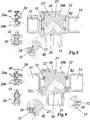
- the volume/pressure-relieving effect of ball groove 28 can best be seen when looking at Figs. 7-10 , where the position of the grooved ball 22' in the 6-way valve is shown for different valve angles of 0° ( Fig. 7 ), 45° ( Fig. 8 ), 52° ( Fig. 9 ) and 60° ( Fig. 10 ).
- Ball 22' is supported in a common valve housing 30 by two opposing sealed ball seats 31 and 32, which are provided at first and second valve ports 33 and 34, coaxial with axis A2 (see for example Fig. 7 ).
- Ball groove 28 lies outside the sealed connection between valve port 33 and connecting channel 29. Consequently, ball groove 28 has no effect on the connection.
- a further rotation of 7° to a valve angle of 52° ends the crossing of ball groove 28 and ball seat 31, so that the relief means is no longer active, when the rotation progresses to 60° ( Fig. 10 ), and more.
- the ball groove 28 allows volume/pressure to instantaneously escape from the coil or load 18 to the heating or cooling circuit expansion tank 16 or 17.
- the relief of pressure through the ball groove 28 is not to be considered “leakage” for the 6-way valve 20. Due to the fact that the 6-way valve 20 has four sealing seats, two seats 31 and 32 on each circuit, if one seat became damaged, the second seat would still seal the circuit preventing unwanted "leakage" to the coil.
- a small groove, easily machined into the sphere of a ball 22' of the 6-way valve 20 allows the relief of volume/pressure while the valve is in the off position, isolated from the volume expansion tanks in the heating and cooling circuits.
- the groove 28 is cut into the ball sphere 22' offset from the primary flow path hole (ball port 24) allowing the remaining sphere surface to provide support of the seats 31, 32 during modulation and while in the fully open flow position.
- the groove 28 is designed so that mixing of water from the heating and cooling circuits could never occur by providing a small dead zone when switching between the circuits (when progressing from 52° to 60° in Figs. 9 and 10 ). This is achieved by choosing the correct geometry of the groove 28 and position on the ball sphere 22'.
- the width and depth of the groove 28 is important to ensure that the groove 28 cannot be plugged by debris, and that, when a certain 6-volt signal is provided to the actuator M of the valve, the groove pressure relief is activated.
- the hysteresis in the actuator M and valve 20 is accounted for in determining the groove width and position on the sphere.
- the ball groove design could be applied to the top or bottom ball of sub-valve 20a or 20b, but not both.
- the ball without the groove is always used as “master” and the ball with the groove is “slave”. This concept also prevents the mixing of water from the heating and cooling circuits 13 and 14.
- the ball groove 28 allows the volume/pressure to escape from two contact points, 180° apart at the point where the groove 28 contacts the sealing surface of the seat 31. Having two contact points reduces the risk of plugging to ensure the groove 28 will operate when needed.
- the proposed 6-way valve 20 is a unique valve due to the fact that has three positions; heating, off and cooling. Each position has an operating zone of 30 degrees where off is located in the middle to prevent the hot and cold water from mixing as the sequence is transitioning from heating to cooling or vice versa. (see Fig. 4 ; the three positions are indicated by 0°, 45° and 90°, whereby 45° is off).
- the 6-way valve 20 with its volume/pressure relief means according to the invention may especially be a DN15 or DN20 valve.
Landscapes
- Engineering & Computer Science (AREA)
- General Engineering & Computer Science (AREA)
- Mechanical Engineering (AREA)
- Chemical & Material Sciences (AREA)
- Combustion & Propulsion (AREA)
- Physics & Mathematics (AREA)
- Thermal Sciences (AREA)
- Life Sciences & Earth Sciences (AREA)
- Sustainable Development (AREA)
- Multiple-Way Valves (AREA)
Claims (6)
- Soupape à 6 voies (20) comprenant deux sous-soupapes à 3 voies similaires (20a, 20b) accouplées mécaniquement l'une à l'autre, de telle sorte que les deux sous-soupapes (20a, 20b) soient toujours dans la même position, chaque sous-soupape (20a, 20b) ayant trois orifices de soupape différents (33, 34, 35) et un organe de soupape (22, 22') avec un canal de connexion interne (29), lequel organe de soupape (22, 22') peut être déplacé entre des première et deuxième positions d'extrémité via une position intermédiaire de telle sorte que dans ladite première position d'extrémité, le premier (33) et le troisième (35) orifice de soupape soient connectés l'un à l'autre au moyen dudit canal de connexion (29), dans ladite deuxième position d'extrémité, le deuxième (34) et le troisième (35) orifice de soupape soient connectés l'un à l'autre au moyen dudit canal de connexion (29), et dans ladite position intermédiaire, ledit canal de connexion (29) soit déconnecté desdits premier et deuxième orifices de soupape (33, 34), lesdites sous-soupapes (20a, 20b) étant disposées le long d'un axe d'actionnement commun (A1), les organes de soupape (22, 22') pouvant être tournés autour dudit axe d'actionnement commun (A1) entre lesdites première et deuxième positions d'extrémité via ladite position intermédiaire et lesdits organes de soupape (22, 22') étant axialement symétriques par rapport audit axe d'actionnement commun (A1), caractérisée en ce qu'un moyen de détente de volume/pression (28) est prévu au niveau de l'un desdits organes de soupape (22, 22'), lequel moyen de détente de volume/pression (28) établit une connexion de détente hydraulique entre ledit premier ou deuxième orifice de soupape (33, 34) et ledit troisième orifice de soupape (35) de la sous-soupape respective (20a ou 20b), lorsque lesdites sous-soupapes (20a, 20b) sont dans ladite position intermédiaire, et est inactif, lorsque lesdites sous-soupapes (20a, 20b) sont dans la première ou la deuxième position d'extrémité, et en ce que ledit moyen de détente de volume/pression comprend une gorge (28) sur la surface de l'un desdits organes de soupape (22, 22').
- Soupape à 6 voies selon la revendication 1, caractérisée en ce que lesdits organes de soupape (22, 22') sont des billes sphériques, en ce que ladite gorge est une gorge à billes (28), en ce que lesdits canaux de connexion internes (29) s'étendent chacun à travers l'une respective desdites billes (22, 22') entre deux orifices de billes (24, 25) dans un plan perpendiculaire audit axe d'actionnement commun (A1), en ce que lesdits organes de soupape (22, 22') sont chacun supportés par des sièges de billes scellés (31, 32) au niveau desdits premier et deuxième orifices de soupape (33, 34), et en ce que ladite gorge à billes (28) sur la surface de l'une desdites billes (22, 22') se présente sous la forme d'un anneau circulaire concentrique autour de l'un desdits orifices de billes (24, 25).
- Soupape à 6 voies selon la revendication 2, caractérisée en ce que le rayon de ladite gorge à billes (28) est choisi de telle sorte que ladite gorge à billes (28) croise deux fois le siège de bille scellé (31, 32) dudit premier ou deuxième orifice de soupape (33, 34), pour ainsi établir ladite connexion de détente hydraulique, lorsque lesdites sous-soupapes (20a, 20b) sont dans ladite position intermédiaire.
- Soupape à 6 voies selon la revendication 2, caractérisée en ce que lesdites sous-soupapes (20a, 20b) sont déplacées entre lesdites première et deuxième positions d'extrémité par une rotation de 90° autour dudit axe d'actionnement commun (A1), et en ce que ladite position intermédiaire est atteinte avec une rotation de +- 45° autour dudit axe d'actionnement commun (A1) à partir de desdites première et deuxième positions d'extrémité.
- Système de chauffage et/ou de ventilation et/ou de climatisation (HVAC), ledit système comprenant un circuit de chauffage (12) et un circuit de refroidissement (13) et au moins une charge (18) qui est connectée audit circuit de chauffage (12) et audit circuit de refroidissement (13) au moyen d'une soupape à 6 voies (20), caractérisé en ce que ladite soupape à 6 voies (20) est une soupape selon l'une quelconque des revendications 1 à 4.
- Système selon la revendication 5, caractérisé en ce que ledit circuit de chauffage (12) et/ou ledit circuit de refroidissement (13) sont connectés à un réservoir d'expansion (16, 17), en ce que la charge (18) est connectée aux troisièmes orifices de soupape (35) desdites deux sous-soupapes (20a, 20b), et en ce que lesdits circuits de chauffage et de refroidissement (12, 13) sont connectés auxdits premiers orifices de soupape (33) et deuxièmes orifices de soupape (34) des deux sous-soupapes (20a, 20b), respectivement, de telle sorte que ladite charge (18) soit connectée à un réservoir d'expansion (16 ou 17) via ledit moyen de détente de volume/pression (28), lorsque lesdites sous-soupapes (20a, 20b) sont dans ladite position intermédiaire.
Applications Claiming Priority (2)
| Application Number | Priority Date | Filing Date | Title |
|---|---|---|---|
| CH7302014 | 2014-05-14 | ||
| PCT/EP2015/059823 WO2015173071A1 (fr) | 2014-05-14 | 2015-05-05 | Vanne à 6 voies et système cvc en étant équipé |
Publications (2)
| Publication Number | Publication Date |
|---|---|
| EP3143315A1 EP3143315A1 (fr) | 2017-03-22 |
| EP3143315B1 true EP3143315B1 (fr) | 2020-03-18 |
Family
ID=51167536
Family Applications (1)
| Application Number | Title | Priority Date | Filing Date |
|---|---|---|---|
| EP15720983.4A Active EP3143315B1 (fr) | 2014-05-14 | 2015-05-05 | Vanne à 6 voies et système cvc en étant équipé |
Country Status (4)
| Country | Link |
|---|---|
| US (1) | US9964329B2 (fr) |
| EP (1) | EP3143315B1 (fr) |
| CN (1) | CN106574732B (fr) |
| WO (1) | WO2015173071A1 (fr) |
Cited By (1)
| Publication number | Priority date | Publication date | Assignee | Title |
|---|---|---|---|---|
| EP4257854A1 (fr) | 2022-04-07 | 2023-10-11 | Berger Holding GmbH & Co. KG | Soupape de régulation du débit dans un système de chauffage et/ou de refroidissement |
Families Citing this family (26)
| Publication number | Priority date | Publication date | Assignee | Title |
|---|---|---|---|---|
| EP3280937B1 (fr) * | 2015-04-09 | 2020-01-08 | Giacomini S.p.A. | Vanne à voies multiples à circuit de dérivation |
| GB2546322A (en) * | 2016-01-15 | 2017-07-19 | Singh Bath Charanjit | A device for flushing a system |
| ITUB20161092A1 (it) * | 2016-02-26 | 2017-08-26 | Bonomi Ind S R L | Valvola a sfera e metodo di fabbricazione |
| US20170328483A1 (en) * | 2016-05-16 | 2017-11-16 | Candy Vanderhoff | Greywater control valve |
| WO2017220263A1 (fr) * | 2016-06-22 | 2017-12-28 | Belimo Holding Ag | Procédé et dispositifs de réglage de réseau de transport de fluide |
| US10465803B2 (en) * | 2016-10-05 | 2019-11-05 | Johnson Controls Technology Company | Multipurpose valve assembly tool |
| DK179453B1 (en) * | 2017-03-24 | 2018-10-19 | Danfoss A/S | BUS ACTUATOR WITH MULTI VALVE COTROL FUNCTION |
| CN107042621B (zh) * | 2017-04-06 | 2023-04-07 | 华东交通大学 | 一种简易可靠的水辅助注塑工艺水气注排控制阀 |
| DK3514419T3 (da) | 2018-01-19 | 2020-08-03 | Siemens Schweiz Ag | Ventil med en bypass-ledning |
| WO2019206510A1 (fr) | 2018-04-23 | 2019-10-31 | Belimo Holding Ag | Vanne à 6 voies et procédé de fabrication d'une vanne à 6 voies |
| JP6996484B2 (ja) | 2018-05-31 | 2022-02-04 | 株式会社デンソー | バルブ装置 |
| CN115289245B (zh) | 2018-05-31 | 2025-12-05 | 株式会社电装 | 阀装置 |
| KR20200067008A (ko) * | 2018-12-03 | 2020-06-11 | 현대자동차주식회사 | 6웨이 밸브 및 이를 포함한 차량용 열관리시스템 |
| FR3091335A1 (fr) * | 2019-01-02 | 2020-07-03 | puybaret | Dispositif d’assemblage pour la régulation des unités terminales de chauffage/refroidissement/climatisation |
| US12298030B2 (en) | 2019-03-17 | 2025-05-13 | Chan How Kiat | Valve system and methods |
| EP3911897A4 (fr) | 2019-03-17 | 2022-03-16 | Ralph Feria | Système de soupape et procédés |
| US11719350B2 (en) * | 2019-06-12 | 2023-08-08 | Vitesco Technologies USA, LLC | Coolant flow control module |
| US11608905B2 (en) | 2019-11-01 | 2023-03-21 | TSI Products, Inc. | Modular valve system |
| CN113757416A (zh) * | 2020-06-05 | 2021-12-07 | 伊利诺斯工具制品有限公司 | 用于冷却剂控制调节器的具有多角度密封的球阀 |
| KR102908683B1 (ko) * | 2020-11-24 | 2026-01-06 | 현대자동차주식회사 | 차량 냉각 시스템용 더블 6-웨이 밸브 |
| EP4191105B1 (fr) * | 2021-12-03 | 2025-08-27 | Airbus Operations, S.L.U. | Soupape pour diviser un circuit hydraulique et circuit hydraulique comprenant ladite soupape |
| US12372023B2 (en) * | 2022-09-26 | 2025-07-29 | Fca Us Llc | Ball valve thermostat assembly |
| US12578115B2 (en) * | 2022-09-30 | 2026-03-17 | Trane International Inc. | Controlled routing of hydronic flow using a distribution area director |
| EP4467855A1 (fr) | 2023-05-23 | 2024-11-27 | Belimo Holding AG | Soupape de commande |
| EP4575279A1 (fr) * | 2023-12-20 | 2025-06-25 | Olab S.r.l. | Soupape à bille, en particulier pour l'utilisation dans les secteurs de climatisation et de réfrigération |
| CN118088733B (zh) * | 2024-04-17 | 2024-07-23 | 新乡市德胜威过滤净化设备有限公司 | 一种模块式串联球阀 |
Family Cites Families (21)
| Publication number | Priority date | Publication date | Assignee | Title |
|---|---|---|---|---|
| US3674052A (en) | 1970-01-12 | 1972-07-04 | Stile Craft Mfg Inc | Ball valve |
| US3770016A (en) * | 1971-11-26 | 1973-11-06 | Crane Canada Ltd | Valve assembly with automatic draining feature |
| US4173234A (en) * | 1977-11-25 | 1979-11-06 | Waterous Company | Transfer valve |
| JPH0355018Y2 (fr) * | 1986-04-21 | 1991-12-05 | ||
| US4915133A (en) * | 1989-03-15 | 1990-04-10 | Harrison C L Scott | Valve device for piping systems |
| CN2144225Y (zh) * | 1992-12-30 | 1993-10-20 | 陈文福 | 五向球阀 |
| CN2237155Y (zh) * | 1995-12-13 | 1996-10-09 | 东莞三荣家用电器有限公司 | 多重控制阀 |
| US6161582A (en) * | 1998-03-30 | 2000-12-19 | Westinghouse Air Brake Company | Ball cock for railway vehicle |
| US6196268B1 (en) * | 1999-12-23 | 2001-03-06 | Tm Industrial Supply, Inc. | Rising stem soft seat plug valve |
| US7089960B2 (en) * | 2003-06-13 | 2006-08-15 | Tlv Co. Ltd. | Ball valve |
| DE202006002375U1 (de) | 2006-02-15 | 2006-04-20 | Festo Ag & Co. | Kugelhahn |
| US7712724B2 (en) * | 2007-06-21 | 2010-05-11 | Tac, Llc | Dynamic ball valve sealing device for three-way valves |
| CN201126043Y (zh) * | 2007-07-19 | 2008-10-01 | 颜善斌 | 一种六通多用阀 |
| EP2195585A1 (fr) | 2007-10-03 | 2010-06-16 | Dux Manufacturing Limited | Système d'eau chaude par énergie solaire et procédé de fonctionnement d'un système d'eau chaude par énergie solaire |
| JP5153349B2 (ja) * | 2008-01-11 | 2013-02-27 | アズビル株式会社 | 三方ボール弁 |
| US7854794B2 (en) * | 2008-07-28 | 2010-12-21 | Barone Michael R | Rotary valve element for twin bed alternative treatment systems |
| US9103449B2 (en) * | 2009-09-02 | 2015-08-11 | Cameron International Corporation | Ball valve stem retaining system |
| CN201891688U (zh) | 2010-07-30 | 2011-07-06 | 三一重工股份有限公司 | 液压阀、液压阀组、液压控制系统及工程机械 |
| CN202493706U (zh) * | 2012-03-29 | 2012-10-17 | 上海如迪流体输送设备有限公司 | 一体式漏式球阀 |
| US8601634B1 (en) * | 2012-07-13 | 2013-12-10 | Gerald A. Stunkard | Pig valve having trunnion supported ball, self-centering seats and universal type mounting flanges |
| CN203146909U (zh) * | 2013-03-07 | 2013-08-21 | 安庆泰邦机械科技有限责任公司 | 一种两位六通快速切换阀 |
-
2015
- 2015-05-05 EP EP15720983.4A patent/EP3143315B1/fr active Active
- 2015-05-05 WO PCT/EP2015/059823 patent/WO2015173071A1/fr not_active Ceased
- 2015-05-05 US US15/308,520 patent/US9964329B2/en active Active
- 2015-05-05 CN CN201580025086.6A patent/CN106574732B/zh active Active
Non-Patent Citations (1)
| Title |
|---|
| None * |
Cited By (2)
| Publication number | Priority date | Publication date | Assignee | Title |
|---|---|---|---|---|
| EP4257854A1 (fr) | 2022-04-07 | 2023-10-11 | Berger Holding GmbH & Co. KG | Soupape de régulation du débit dans un système de chauffage et/ou de refroidissement |
| DE102022108365A1 (de) | 2022-04-07 | 2023-10-12 | Berger Holding GmbH & Co. KG | Ventil zur Durchflussregelung in einem Heiz- und/oder Kühlsystem |
Also Published As
| Publication number | Publication date |
|---|---|
| US9964329B2 (en) | 2018-05-08 |
| EP3143315A1 (fr) | 2017-03-22 |
| WO2015173071A1 (fr) | 2015-11-19 |
| CN106574732A (zh) | 2017-04-19 |
| CN106574732B (zh) | 2019-07-05 |
| US20170067665A1 (en) | 2017-03-09 |
Similar Documents
| Publication | Publication Date | Title |
|---|---|---|
| US9964329B2 (en) | 6-way valve and HVAC system with such a 6-way valve | |
| EP3280937B1 (fr) | Vanne à voies multiples à circuit de dérivation | |
| CN116498779B (zh) | 多通阀门及多通阀门的阀芯位置调整方法 | |
| CN109424767B (zh) | 组合多端口阀 | |
| EP4350182B1 (fr) | Soupape à voies multiples | |
| US9482365B2 (en) | Rotary valve | |
| US11796073B2 (en) | Six port valve | |
| EP3260745A1 (fr) | Vanne de contrôle de flux | |
| US20220146003A1 (en) | Three-way water valve | |
| JPH07103614A (ja) | 流体流のための弁構造 | |
| CN220102162U (zh) | 多路阀 | |
| US20120049096A1 (en) | Rotary valve | |
| CN113027846B (zh) | 一种同步动作的轴配流开关换向多路阀 | |
| CN222543101U (zh) | 多路阀 | |
| EP3680524B1 (fr) | Mécanisme d'actionnement | |
| EP1862712B1 (fr) | Valve et dispositif de mélange | |
| EP3260746B1 (fr) | Vanne de régulation d'écoulement | |
| CN112901586B (zh) | 一种顺序动作的轴配流比例换向多路阀 | |
| CN118328178A (zh) | 具有双致动器的多路阀 | |
| GB2199119A (en) | Improvements in or relating to valves | |
| KR102579769B1 (ko) | 팽창밸브 기능을 갖는 통합형 유체제어밸브 | |
| US3308721A (en) | Hydraulic rotary servo mechanism | |
| JP2020115043A (ja) | 流路切換弁 | |
| CN112983917B (zh) | 一种顺序动作的轴配流开关换向多路阀 | |
| WO1989005937A1 (fr) | Soupape de regulation d'ecoulement fluide |
Legal Events
| Date | Code | Title | Description |
|---|---|---|---|
| STAA | Information on the status of an ep patent application or granted ep patent |
Free format text: STATUS: THE INTERNATIONAL PUBLICATION HAS BEEN MADE |
|
| PUAI | Public reference made under article 153(3) epc to a published international application that has entered the european phase |
Free format text: ORIGINAL CODE: 0009012 |
|
| STAA | Information on the status of an ep patent application or granted ep patent |
Free format text: STATUS: REQUEST FOR EXAMINATION WAS MADE |
|
| 17P | Request for examination filed |
Effective date: 20161114 |
|
| AK | Designated contracting states |
Kind code of ref document: A1 Designated state(s): AL AT BE BG CH CY CZ DE DK EE ES FI FR GB GR HR HU IE IS IT LI LT LU LV MC MK MT NL NO PL PT RO RS SE SI SK SM TR |
|
| AX | Request for extension of the european patent |
Extension state: BA ME |
|
| RIN1 | Information on inventor provided before grant (corrected) |
Inventor name: KELLER, URS Inventor name: WHITMORE, RYAN Inventor name: KAUFMAN, DARYL Inventor name: HOTZ, BEAT |
|
| TPAC | Observations filed by third parties |
Free format text: ORIGINAL CODE: EPIDOSNTIPA |
|
| TPAC | Observations filed by third parties |
Free format text: ORIGINAL CODE: EPIDOSNTIPA |
|
| TPAC | Observations filed by third parties |
Free format text: ORIGINAL CODE: EPIDOSNTIPA |
|
| DAV | Request for validation of the european patent (deleted) | ||
| DAX | Request for extension of the european patent (deleted) | ||
| STAA | Information on the status of an ep patent application or granted ep patent |
Free format text: STATUS: EXAMINATION IS IN PROGRESS |
|
| 17Q | First examination report despatched |
Effective date: 20180102 |
|
| GRAP | Despatch of communication of intention to grant a patent |
Free format text: ORIGINAL CODE: EPIDOSNIGR1 |
|
| STAA | Information on the status of an ep patent application or granted ep patent |
Free format text: STATUS: GRANT OF PATENT IS INTENDED |
|
| INTG | Intention to grant announced |
Effective date: 20190816 |
|
| GRAJ | Information related to disapproval of communication of intention to grant by the applicant or resumption of examination proceedings by the epo deleted |
Free format text: ORIGINAL CODE: EPIDOSDIGR1 |
|
| STAA | Information on the status of an ep patent application or granted ep patent |
Free format text: STATUS: EXAMINATION IS IN PROGRESS |
|
| INTC | Intention to grant announced (deleted) | ||
| RIN1 | Information on inventor provided before grant (corrected) |
Inventor name: HOTZ, BEAT Inventor name: KELLER, URS Inventor name: KAUFMAN, DARYL Inventor name: WHITMORE, RYAN |
|
| GRAS | Grant fee paid |
Free format text: ORIGINAL CODE: EPIDOSNIGR3 |
|
| STAA | Information on the status of an ep patent application or granted ep patent |
Free format text: STATUS: GRANT OF PATENT IS INTENDED |
|
| GRAP | Despatch of communication of intention to grant a patent |
Free format text: ORIGINAL CODE: EPIDOSNIGR1 |
|
| GRAA | (expected) grant |
Free format text: ORIGINAL CODE: 0009210 |
|
| STAA | Information on the status of an ep patent application or granted ep patent |
Free format text: STATUS: THE PATENT HAS BEEN GRANTED |
|
| INTG | Intention to grant announced |
Effective date: 20200131 |
|
| AK | Designated contracting states |
Kind code of ref document: B1 Designated state(s): AL AT BE BG CH CY CZ DE DK EE ES FI FR GB GR HR HU IE IS IT LI LT LU LV MC MK MT NL NO PL PT RO RS SE SI SK SM TR |
|
| REG | Reference to a national code |
Ref country code: GB Ref legal event code: FG4D |
|
| REG | Reference to a national code |
Ref country code: DE Ref legal event code: R096 Ref document number: 602015048967 Country of ref document: DE |
|
| REG | Reference to a national code |
Ref country code: AT Ref legal event code: REF Ref document number: 1246273 Country of ref document: AT Kind code of ref document: T Effective date: 20200415 Ref country code: IE Ref legal event code: FG4D |
|
| PG25 | Lapsed in a contracting state [announced via postgrant information from national office to epo] |
Ref country code: RS Free format text: LAPSE BECAUSE OF FAILURE TO SUBMIT A TRANSLATION OF THE DESCRIPTION OR TO PAY THE FEE WITHIN THE PRESCRIBED TIME-LIMIT Effective date: 20200318 Ref country code: FI Free format text: LAPSE BECAUSE OF FAILURE TO SUBMIT A TRANSLATION OF THE DESCRIPTION OR TO PAY THE FEE WITHIN THE PRESCRIBED TIME-LIMIT Effective date: 20200318 Ref country code: NO Free format text: LAPSE BECAUSE OF FAILURE TO SUBMIT A TRANSLATION OF THE DESCRIPTION OR TO PAY THE FEE WITHIN THE PRESCRIBED TIME-LIMIT Effective date: 20200618 |
|
| REG | Reference to a national code |
Ref country code: NL Ref legal event code: MP Effective date: 20200318 |
|
| PG25 | Lapsed in a contracting state [announced via postgrant information from national office to epo] |
Ref country code: SE Free format text: LAPSE BECAUSE OF FAILURE TO SUBMIT A TRANSLATION OF THE DESCRIPTION OR TO PAY THE FEE WITHIN THE PRESCRIBED TIME-LIMIT Effective date: 20200318 Ref country code: HR Free format text: LAPSE BECAUSE OF FAILURE TO SUBMIT A TRANSLATION OF THE DESCRIPTION OR TO PAY THE FEE WITHIN THE PRESCRIBED TIME-LIMIT Effective date: 20200318 Ref country code: LV Free format text: LAPSE BECAUSE OF FAILURE TO SUBMIT A TRANSLATION OF THE DESCRIPTION OR TO PAY THE FEE WITHIN THE PRESCRIBED TIME-LIMIT Effective date: 20200318 Ref country code: GR Free format text: LAPSE BECAUSE OF FAILURE TO SUBMIT A TRANSLATION OF THE DESCRIPTION OR TO PAY THE FEE WITHIN THE PRESCRIBED TIME-LIMIT Effective date: 20200619 Ref country code: BG Free format text: LAPSE BECAUSE OF FAILURE TO SUBMIT A TRANSLATION OF THE DESCRIPTION OR TO PAY THE FEE WITHIN THE PRESCRIBED TIME-LIMIT Effective date: 20200618 |
|
| REG | Reference to a national code |
Ref country code: LT Ref legal event code: MG4D |
|
| PG25 | Lapsed in a contracting state [announced via postgrant information from national office to epo] |
Ref country code: NL Free format text: LAPSE BECAUSE OF FAILURE TO SUBMIT A TRANSLATION OF THE DESCRIPTION OR TO PAY THE FEE WITHIN THE PRESCRIBED TIME-LIMIT Effective date: 20200318 |
|
| PG25 | Lapsed in a contracting state [announced via postgrant information from national office to epo] |
Ref country code: RO Free format text: LAPSE BECAUSE OF FAILURE TO SUBMIT A TRANSLATION OF THE DESCRIPTION OR TO PAY THE FEE WITHIN THE PRESCRIBED TIME-LIMIT Effective date: 20200318 Ref country code: CZ Free format text: LAPSE BECAUSE OF FAILURE TO SUBMIT A TRANSLATION OF THE DESCRIPTION OR TO PAY THE FEE WITHIN THE PRESCRIBED TIME-LIMIT Effective date: 20200318 Ref country code: SK Free format text: LAPSE BECAUSE OF FAILURE TO SUBMIT A TRANSLATION OF THE DESCRIPTION OR TO PAY THE FEE WITHIN THE PRESCRIBED TIME-LIMIT Effective date: 20200318 Ref country code: IS Free format text: LAPSE BECAUSE OF FAILURE TO SUBMIT A TRANSLATION OF THE DESCRIPTION OR TO PAY THE FEE WITHIN THE PRESCRIBED TIME-LIMIT Effective date: 20200718 Ref country code: LT Free format text: LAPSE BECAUSE OF FAILURE TO SUBMIT A TRANSLATION OF THE DESCRIPTION OR TO PAY THE FEE WITHIN THE PRESCRIBED TIME-LIMIT Effective date: 20200318 Ref country code: PT Free format text: LAPSE BECAUSE OF FAILURE TO SUBMIT A TRANSLATION OF THE DESCRIPTION OR TO PAY THE FEE WITHIN THE PRESCRIBED TIME-LIMIT Effective date: 20200812 Ref country code: SM Free format text: LAPSE BECAUSE OF FAILURE TO SUBMIT A TRANSLATION OF THE DESCRIPTION OR TO PAY THE FEE WITHIN THE PRESCRIBED TIME-LIMIT Effective date: 20200318 Ref country code: EE Free format text: LAPSE BECAUSE OF FAILURE TO SUBMIT A TRANSLATION OF THE DESCRIPTION OR TO PAY THE FEE WITHIN THE PRESCRIBED TIME-LIMIT Effective date: 20200318 |
|
| REG | Reference to a national code |
Ref country code: AT Ref legal event code: MK05 Ref document number: 1246273 Country of ref document: AT Kind code of ref document: T Effective date: 20200318 |
|
| REG | Reference to a national code |
Ref country code: DE Ref legal event code: R097 Ref document number: 602015048967 Country of ref document: DE |
|
| PLBE | No opposition filed within time limit |
Free format text: ORIGINAL CODE: 0009261 |
|
| STAA | Information on the status of an ep patent application or granted ep patent |
Free format text: STATUS: NO OPPOSITION FILED WITHIN TIME LIMIT |
|
| PG25 | Lapsed in a contracting state [announced via postgrant information from national office to epo] |
Ref country code: AT Free format text: LAPSE BECAUSE OF FAILURE TO SUBMIT A TRANSLATION OF THE DESCRIPTION OR TO PAY THE FEE WITHIN THE PRESCRIBED TIME-LIMIT Effective date: 20200318 Ref country code: ES Free format text: LAPSE BECAUSE OF FAILURE TO SUBMIT A TRANSLATION OF THE DESCRIPTION OR TO PAY THE FEE WITHIN THE PRESCRIBED TIME-LIMIT Effective date: 20200318 Ref country code: MC Free format text: LAPSE BECAUSE OF FAILURE TO SUBMIT A TRANSLATION OF THE DESCRIPTION OR TO PAY THE FEE WITHIN THE PRESCRIBED TIME-LIMIT Effective date: 20200318 Ref country code: DK Free format text: LAPSE BECAUSE OF FAILURE TO SUBMIT A TRANSLATION OF THE DESCRIPTION OR TO PAY THE FEE WITHIN THE PRESCRIBED TIME-LIMIT Effective date: 20200318 |
|
| 26N | No opposition filed |
Effective date: 20201221 |
|
| PG25 | Lapsed in a contracting state [announced via postgrant information from national office to epo] |
Ref country code: PL Free format text: LAPSE BECAUSE OF FAILURE TO SUBMIT A TRANSLATION OF THE DESCRIPTION OR TO PAY THE FEE WITHIN THE PRESCRIBED TIME-LIMIT Effective date: 20200318 |
|
| REG | Reference to a national code |
Ref country code: BE Ref legal event code: MM Effective date: 20200531 |
|
| GBPC | Gb: european patent ceased through non-payment of renewal fee |
Effective date: 20200618 |
|
| PG25 | Lapsed in a contracting state [announced via postgrant information from national office to epo] |
Ref country code: LU Free format text: LAPSE BECAUSE OF NON-PAYMENT OF DUE FEES Effective date: 20200505 |
|
| PG25 | Lapsed in a contracting state [announced via postgrant information from national office to epo] |
Ref country code: IE Free format text: LAPSE BECAUSE OF NON-PAYMENT OF DUE FEES Effective date: 20200505 Ref country code: GB Free format text: LAPSE BECAUSE OF NON-PAYMENT OF DUE FEES Effective date: 20200618 |
|
| PG25 | Lapsed in a contracting state [announced via postgrant information from national office to epo] |
Ref country code: BE Free format text: LAPSE BECAUSE OF NON-PAYMENT OF DUE FEES Effective date: 20200531 Ref country code: SI Free format text: LAPSE BECAUSE OF FAILURE TO SUBMIT A TRANSLATION OF THE DESCRIPTION OR TO PAY THE FEE WITHIN THE PRESCRIBED TIME-LIMIT Effective date: 20200318 |
|
| PG25 | Lapsed in a contracting state [announced via postgrant information from national office to epo] |
Ref country code: TR Free format text: LAPSE BECAUSE OF FAILURE TO SUBMIT A TRANSLATION OF THE DESCRIPTION OR TO PAY THE FEE WITHIN THE PRESCRIBED TIME-LIMIT Effective date: 20200318 Ref country code: MT Free format text: LAPSE BECAUSE OF FAILURE TO SUBMIT A TRANSLATION OF THE DESCRIPTION OR TO PAY THE FEE WITHIN THE PRESCRIBED TIME-LIMIT Effective date: 20200318 Ref country code: CY Free format text: LAPSE BECAUSE OF FAILURE TO SUBMIT A TRANSLATION OF THE DESCRIPTION OR TO PAY THE FEE WITHIN THE PRESCRIBED TIME-LIMIT Effective date: 20200318 |
|
| PG25 | Lapsed in a contracting state [announced via postgrant information from national office to epo] |
Ref country code: MK Free format text: LAPSE BECAUSE OF FAILURE TO SUBMIT A TRANSLATION OF THE DESCRIPTION OR TO PAY THE FEE WITHIN THE PRESCRIBED TIME-LIMIT Effective date: 20200318 Ref country code: AL Free format text: LAPSE BECAUSE OF FAILURE TO SUBMIT A TRANSLATION OF THE DESCRIPTION OR TO PAY THE FEE WITHIN THE PRESCRIBED TIME-LIMIT Effective date: 20200318 |
|
| P01 | Opt-out of the competence of the unified patent court (upc) registered |
Effective date: 20230513 |
|
| PGFP | Annual fee paid to national office [announced via postgrant information from national office to epo] |
Ref country code: DE Payment date: 20250519 Year of fee payment: 11 |
|
| PGFP | Annual fee paid to national office [announced via postgrant information from national office to epo] |
Ref country code: IT Payment date: 20250530 Year of fee payment: 11 |
|
| PGFP | Annual fee paid to national office [announced via postgrant information from national office to epo] |
Ref country code: FR Payment date: 20250521 Year of fee payment: 11 |
|
| PGFP | Annual fee paid to national office [announced via postgrant information from national office to epo] |
Ref country code: CH Payment date: 20250601 Year of fee payment: 11 |