EP3143328B1 - Arrangement for generating light effects having a shadowing function - Google Patents
Arrangement for generating light effects having a shadowing function Download PDFInfo
- Publication number
- EP3143328B1 EP3143328B1 EP15717117.4A EP15717117A EP3143328B1 EP 3143328 B1 EP3143328 B1 EP 3143328B1 EP 15717117 A EP15717117 A EP 15717117A EP 3143328 B1 EP3143328 B1 EP 3143328B1
- Authority
- EP
- European Patent Office
- Prior art keywords
- light
- surface structure
- darkening
- sheet
- arrangement according
- Prior art date
- Legal status (The legal status is an assumption and is not a legal conclusion. Google has not performed a legal analysis and makes no representation as to the accuracy of the status listed.)
- Active
Links
Images

Classifications
-
- F—MECHANICAL ENGINEERING; LIGHTING; HEATING; WEAPONS; BLASTING
- F21—LIGHTING
- F21V—FUNCTIONAL FEATURES OR DETAILS OF LIGHTING DEVICES OR SYSTEMS THEREOF; STRUCTURAL COMBINATIONS OF LIGHTING DEVICES WITH OTHER ARTICLES, NOT OTHERWISE PROVIDED FOR
- F21V1/00—Shades for light sources, i.e. lampshades for table, floor, wall or ceiling lamps
- F21V1/12—Composite shades, i.e. shades being made of distinct parts
-
- B—PERFORMING OPERATIONS; TRANSPORTING
- B32—LAYERED PRODUCTS
- B32B—LAYERED PRODUCTS, i.e. PRODUCTS BUILT-UP OF STRATA OF FLAT OR NON-FLAT, e.g. CELLULAR OR HONEYCOMB, FORM
- B32B5/00—Layered products characterised by the non- homogeneity or physical structure, i.e. comprising a fibrous, filamentary, particulate or foam layer; Layered products characterised by having a layer differing constitutionally or physically in different parts
- B32B5/22—Layered products characterised by the non- homogeneity or physical structure, i.e. comprising a fibrous, filamentary, particulate or foam layer; Layered products characterised by having a layer differing constitutionally or physically in different parts characterised by the presence of two or more layers which are next to each other and are fibrous, filamentary, formed of particles or foamed
- B32B5/24—Layered products characterised by the non- homogeneity or physical structure, i.e. comprising a fibrous, filamentary, particulate or foam layer; Layered products characterised by having a layer differing constitutionally or physically in different parts characterised by the presence of two or more layers which are next to each other and are fibrous, filamentary, formed of particles or foamed one layer being a fibrous or filamentary layer
- B32B5/26—Layered products characterised by the non- homogeneity or physical structure, i.e. comprising a fibrous, filamentary, particulate or foam layer; Layered products characterised by having a layer differing constitutionally or physically in different parts characterised by the presence of two or more layers which are next to each other and are fibrous, filamentary, formed of particles or foamed one layer being a fibrous or filamentary layer another layer next to it also being fibrous or filamentary
-
- F—MECHANICAL ENGINEERING; LIGHTING; HEATING; WEAPONS; BLASTING
- F21—LIGHTING
- F21V—FUNCTIONAL FEATURES OR DETAILS OF LIGHTING DEVICES OR SYSTEMS THEREOF; STRUCTURAL COMBINATIONS OF LIGHTING DEVICES WITH OTHER ARTICLES, NOT OTHERWISE PROVIDED FOR
- F21V11/00—Screens not covered by groups F21V1/00, F21V3/00, F21V7/00 or F21V9/00
- F21V11/08—Screens not covered by groups F21V1/00, F21V3/00, F21V7/00 or F21V9/00 using diaphragms containing one or more apertures
- F21V11/14—Screens not covered by groups F21V1/00, F21V3/00, F21V7/00 or F21V9/00 using diaphragms containing one or more apertures with many small apertures
-
- F—MECHANICAL ENGINEERING; LIGHTING; HEATING; WEAPONS; BLASTING
- F21—LIGHTING
- F21V—FUNCTIONAL FEATURES OR DETAILS OF LIGHTING DEVICES OR SYSTEMS THEREOF; STRUCTURAL COMBINATIONS OF LIGHTING DEVICES WITH OTHER ARTICLES, NOT OTHERWISE PROVIDED FOR
- F21V33/00—Structural combinations of lighting devices with other articles, not otherwise provided for
- F21V33/0004—Personal or domestic articles
- F21V33/0024—Household or table equipment
-
- F—MECHANICAL ENGINEERING; LIGHTING; HEATING; WEAPONS; BLASTING
- F21—LIGHTING
- F21V—FUNCTIONAL FEATURES OR DETAILS OF LIGHTING DEVICES OR SYSTEMS THEREOF; STRUCTURAL COMBINATIONS OF LIGHTING DEVICES WITH OTHER ARTICLES, NOT OTHERWISE PROVIDED FOR
- F21V33/00—Structural combinations of lighting devices with other articles, not otherwise provided for
- F21V33/006—General building constructions or finishing work for buildings, e.g. roofs, gutters, stairs or floors; Garden equipment; Sunshades or parasols
-
- F—MECHANICAL ENGINEERING; LIGHTING; HEATING; WEAPONS; BLASTING
- F21—LIGHTING
- F21V—FUNCTIONAL FEATURES OR DETAILS OF LIGHTING DEVICES OR SYSTEMS THEREOF; STRUCTURAL COMBINATIONS OF LIGHTING DEVICES WITH OTHER ARTICLES, NOT OTHERWISE PROVIDED FOR
- F21V11/00—Screens not covered by groups F21V1/00, F21V3/00, F21V7/00 or F21V9/00
- F21V11/16—Screens not covered by groups F21V1/00, F21V3/00, F21V7/00 or F21V9/00 using sheets without apertures, e.g. fixed
- F21V11/18—Screens not covered by groups F21V1/00, F21V3/00, F21V7/00 or F21V9/00 using sheets without apertures, e.g. fixed movable, e.g. flaps, slides
- F21V11/186—Screens not covered by groups F21V1/00, F21V3/00, F21V7/00 or F21V9/00 using sheets without apertures, e.g. fixed movable, e.g. flaps, slides slidable
-
- F—MECHANICAL ENGINEERING; LIGHTING; HEATING; WEAPONS; BLASTING
- F21—LIGHTING
- F21W—INDEXING SCHEME ASSOCIATED WITH SUBCLASSES F21K, F21L, F21S and F21V, RELATING TO USES OR APPLICATIONS OF LIGHTING DEVICES OR SYSTEMS
- F21W2121/00—Use or application of lighting devices or systems for decorative purposes, not provided for in codes F21W2102/00 – F21W2107/00
Definitions
- the invention relates to an arrangement for generating light effects.
- Such an arrangement is for example off WO 2011/015621 A1 known.
- the known arrangement comprises a light source and a fabric arranged away from the light source.
- This textile fabric is designed as a fabric and has a warp thread layer and a weft thread layer.
- the light emitted by the light source can be reflected or deflected at the warp threads or weft threads.
- On the side facing away from the light source side of the fabric thereby creates a light pattern that can produce a three-dimensional lighting effect for the viewer.
- Such arrangements are illuminated, for example, by means of light-emitting diodes or other light sources. They can be used for decorative purposes.
- EP 1 371 897 A1 describes a lit picture frame with a light panel as the backlight, a decorative image arranged above it and a filter.
- the arrangement has a plurality of webs arranged at least partially overlapping in the viewing direction of a viewer.
- the viewing direction is oriented substantially perpendicular to the plane of extent of the sheets.
- the assembly has a blackout sheet.
- the darkening sheet has a light incident side and a light emission side. The light incident side faces an artificial or natural light source.
- the darkening sheet has at least one passage area and at least one shielding area. The light incident on the shading sheet on the light incident side passes at least through the at least one passage area and exits from the passage area on the light exit side.
- the at least one shielding area can almost completely shield the light.
- the blackout sheet can meet the requirements of a so-called "black-out material". At least the intensity of the light emerging at the light exit side in the passband is greater than in the shielding region, so that a sufficient intensity difference of the light between the darker shielding region and the brighter passage region on the light exit side is ensured.
- the blackout sheet is formed by a black-out sheet, wherein the at least one through-band extends through recesses at least in the at least one blackout sheet of the blackout sheet is formed.
- the at least one passage region may have any shape or form.
- one or more passbands may form a logo, lettering, pattern, or the like. It can also be used for aesthetic interior design.
- the total area of the one or more passage areas is at least a factor of 10 smaller than the entire remaining area of the at least one shielding area.
- the arrangement also has an effect surface structure.
- the effect sheet is made of a textile material, preferably a fabric.
- the arrangement of the yarns or threads in the textile material the desired light effect can be effected.
- the effect sheet has a back side facing the darkening sheet and a back side opposite the back side. The light emerging from the passage areas of the darkening sheet strikes the back of the effect sheet and is reflected and / or scattered and / or broken and / or diffracted at the yarns. As a result, the light pattern or the light effect is produced in the viewing direction on the viewing side.
- the blackout sheet Due to the configuration of the arrangement according to the invention, it is possible on the light incidence side of the blackout sheet to arrange other than point or hemispherical light sources.
- the blackout area acts as a kind of aperture. It is thus possible to produce more complex light patterns or lettering with light effects.
- the natural light in particular sunlight, can also be used as the light source via the darkening surface.
- the arrangement includes a divergence sheet in addition to the darkening sheet and the effect sheet to convert the parallel sunlight into divergent light.
- hemispherically radiated and preferably approximately isotropic light can be generated at the at least one transmission region via the diverging surface structure.
- the divergence sheet and the blackout sheet form, as it were, one or more virtual dot-shaped light sources in the at least one passband.
- the arrangement is also suitable as a sunscreen or for shading and can therefore be used in sun blinds, umbrellas, blackout blinds or the like facilities.
- the intensity of the light passing through the at least one transmission region is at least 5 to 10 times, preferably 10 to 30 times, greater than the intensity of the light passing through the at least one shielding region.
- the divergence sheet is disposed between the blackout sheet and the effect sheet.
- the divergence sheet may also be part of the blackout sheet.
- the divergence sheet and the darkening surface are flat against each other and, for example, are bonded together in a material-locking manner.
- the divergent light-generating material of the diverging sheet is arranged very close to the at least one passage region.
- the handling of the arrangement is simplified when the divergence sheet and the darkening sheet are firmly bonded together.
- the divergent sheet may comprise a film and / or fibrous material and / or textile material.
- a fibrous or nonwoven material having sufficient fiber spacing may be used to diffuse the substantially parallel light.
- the blackout sheet and / or divergence sheet and / or effect sheet may each consist of one or more adjacent layers.
- a multilayer effect surface may be advantageous for achieving the desired light effects or light patterns.
- the blackout sheet has a backing layer which may be, for example, a sheet material and / or a fibrous material and / or a textile material.
- a backing layer which may be, for example, a sheet material and / or a fibrous material and / or a textile material.
- On this carrier layer is at least one darkening position arranged.
- one or more blackout layers can be arranged on both sides of the carrier layer.
- the at least one passage region may be formed by an aperture in the blackout sheet which eliminates all layers of the blackout sheet.
- the carrier layer can be retained in the passage region and only the darkening layers arranged thereon are left out.
- the carrier layer can serve as a divergence layer and thus for generating the divergent light.
- the carrier layer can thus be part of the divergence sheet or form the divergent sheet.
- the blackout sheet and / or the effect sheet is wound up and unwound on a respective winding shaft.
- the darkening sheet and / or the effect sheet can be made as a pleat and be pulled or pulled apart like an accordion. It is possible - as mentioned above - that the Divergenz vomgetrucke is firmly and extensively connected to the blackout sheet.
- the distance between the blackout sheet and the effect sheet or between the blackout sheet and the diverging sheet may be formed by an air gap and / or by a bonding layer.
- the connection layer consists, at least in the region in which the light propagates from the at least one passage region or the divergence surface to the rear side of the effect surface, for the used light wavelength or the wavelength range of light used transparent material.
- the connecting layer can be embodied, as far as is technically possible, opaque to light, at least at one or more edge regions.
- the connection layer can also connect the effect surface structure with the Divergenz vomgetrucke or the blackout sheet only locally to specify the distance.
- the darkening sheet and the effect sheet may together or in each case comprise a tension rod, which is displaceably guided in a guide device.
- This embodiment may be used, for example, when the blackout sheet and / or the effect sheet is made as a blind or pleated.
- the blackout sheet has two mutually displaceable blackout layers, each having at least one passage area and at least one shielding area.
- the passage areas and shielding areas are configured identically or contoured.
- a complete darkening can thus be achieved if the passage region of one darkening layer coincides with the shielding region of the other darkening layer.
- a maximum passage of light through the passbands can be achieved if the two passbands of the two blackout layers completely cover each other.
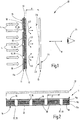
- Figures 1 and 2 is schematically illustrated in a second view of the multilayer structure of an embodiment of an arrangement 10 for generating light effects.
- the assembly 10 includes a blackout sheet 11, a divergent sheet 12, and an effect sheet 13.
- the darkening sheet 11 has a light incident side 15 and an opposite light exit side 16.
- At least one passage region 17 has at least one shielding region 18.
- the light L emitted from an artificial or natural light source and impinging on the light incident side 15 of the obscuration surface genome 11 passes through the obscurant sheet 11 at least through the at least one passage portion 17 and exits on the light exit side 16.
- the darkening surface structure 11 is configured in such a way that the intensity reduction of the light impinging on the light incidence side 15 in the at least one shielding region 18 is significantly greater and, for example, at least ten times greater than the intensity reduction of the light passing through the at least one transmissive region 17.
- the incident light L is almost completely shielded so that only a negligible proportion of light can pass through the shielding area 18.
- the shading sheet 11 is preferably constructed in the at least one shielding region 18 so as to satisfy the requirements for so-called "black-out" material.
- the at least one passage region 17 is formed by a respective recess 19 in the darkening surface 11, so that the light L there can pass unhindered from the light incident side 15 to the light exit side 16.
- a plurality of recesses 19 are provided in the form of cylindrical holes in the darkening sheet 11.
- the shape or contour of the recesses may be chosen differently from a circular cross-section also different.
- the total cross-sectional area of the recesses 19 is smaller and preferably smaller by at least a factor of 10 than the entire area of the shielding area 18 surrounding the recesses 19.
- the distance D between two immediately adjacent recesses 19 be in a spatial direction in which the darkening sheet 11 extends is larger and preferably at least twice as large as the dimension of the recess 19 in this spatial direction.
- the blackout sheet 11 In the embodiment of the blackout sheet 11 according to FIG. 1 only a single darkening 11a is provided. In contrast, the embodiments of the shading sheets 11 are as shown in FIG Figures 2 and 3 executed with multiple blackout layers 11a.
- the blackout sheet 11 has a carrier sheet 11b. On this carrier layer 11b is applied to one and, for example, on both sides in each case at least one darkening 11a.
- the carrier layer may preferably be a textile material, such as a fabric or a knit fabric.
- One or more darkening layers 11a are then applied to the carrier layer 11b on one or both sides.
- the darkening layers 11a are preferably made of a plastic material. The number and the thickness of the darkening layers are selected so as to achieve the required shielding effect for the incident light L required in the shielding region 18.
- FIG. 2 illustrates apertures are introduced into the blackout sheet 11, which completely pass through all the layers 11a, 11b. This can be done by cutting, for example, laser cutting, punching, or other suitable separation process.
- the recesses 19 are formed in the applied darkening layers 11a (FIG. FIG. 3 ).
- the recesses 19 are only present in the blackout layers 11a and do not enforce the carrier layer 11b.
- the recesses 19 are arranged in the darkening layers 11b at least substantially in alignment in a viewing direction B.
- the viewing direction B is oriented at right angles to the plane of extent in which the blackout sheet 11 extends.
- the carrier layer 11b may be part of the divergence sheet 12 or form this in this embodiment. The function of the diverging sheet 12 will be explained below.
- the divergence sheet 12 serves to diffuse parallel light L and to generate in the region of the light exit side 16 at the at least one passage region 17 divergent light beams LD. If the passage regions 17 or recesses 19 are sufficiently small in cross-section, then a virtual punctiform light source is produced on the light exit side 16 at each recess 19 in combination with the diverging surfaces 12, emitting hemispherical divergent light beams LD preferably isotropically technically possible.
- the divergence sheet 12 may be a film and / or a textile material and / or a fiber material and be embodied, for example, as a woven fabric, knitted fabric, nonwoven fabric or cellulose.
- the diverging sheet 12 is flat and fixed to the blackout sheet 11. It can for example be arranged directly on the light exit side 16 of the darkening surface 11 ( FIG. 1 ) or alternatively be integrated as a layer in the darkening sheet 11.
- the divergence sheet 12 may be formed by the backing sheet 11b and may be coated with a blackout sheet 11a from one or both sides.
- the darkening sheet 11 thus has the function of a kind of aperture and generates at the at least one passage area 17 together with the divergence sheet 12 the divergent light beams LD.
- the divergent light beams LD strike the effect surface formation 13, which is arranged at a distance A from the divergence surface formation 12.
- the effect sheet 13 has a back side 23, which faces the divergence sheet 12 and the light exit side 16 of the darkening sheet 11, respectively.
- the divergent light beams LD strike this rear side 23.
- the effect surface structure 13 has a viewing side 24.
- the viewing side 24 faces an observer 25.
- the effect surface structure 13 preferably comprises a textile material and / or a fiber material and / or a foil material.
- the effect sheet 13 may be made of one or more yarns, in the embodiment as a fabric.
- the divergent light beams LD impinge on the back side 23 and are at least partially scattered and / or reflected and / or refracted by the effect surface fabric and, for example, at respective yarn sections.
- a predetermined, desired lighting effect for the viewer 25 can be generated.
- a three-dimensional light effect 26 can arise.
- star-shaped beams can be generated around the virtual light sources at the recesses 19, which for the viewer 25 also extend from the plane of the effect surface structure 13 backwards into the room. Ellipse or line patterns can also be generated.
- the inventive arrangement 10 can work with any natural or artificial light sources.
- the sunlight striking the earth is parallel, so that no light effect could be generated by the effect surface structure 13.
- the arrangement 10 generates the divergent light beams LD from the parallel light L and can thus generate a light effect 26 even in sunlight.
- the assembly 10 is therefore suitable for use with sun protection or shading devices, such as parasols, sun sails, roller blinds or the like. For example, when darkening a room during the day, a special lighting effect can still be created on the darkened windows.
- the divergence sheet 12 may also be eliminated.
- FIGS. 4 and 5 schematically two embodiments of a structural design of the arrangement 10 are illustrated.
- the arrangement 10 is designed in the form of a double roller blind 30.
- the darkening sheet 11 and the divergence sheet 12 are directly adjacent to each other wound on a common winding shaft 31 of a first shade 32.
- the effect surface structure 13 is wound on a winding shaft 31 of a second roller blind 33.
- the two blinds 32, 33 may be coupled together, so that when turning a winding shaft 31 of a blinds 32 or 33 and the winding shaft 31 of the other blinds 33 and 32 respectively rotates. This can be achieved, for example, in that the fabrics 11, 12, 13 are connected at their respective free end to a common tie rod 34.
- the winding shafts 31 of the two blinds 32, 33 can also be coupled to one another via a coupling means, for example a gear, a belt or the like.
- a coupling means for example a gear, a belt or the like.
- a connection of the effect surface structure 13 with the other Flaähhenformen 11, 12 omitted.
- the arrangement of the blinds 32, 33 is such that the distance A is set between the effect surface structure 13 and the divergence surface 12.
- FIG. 5 is a further constructive embodiment of the arrangement 10 illustrated.
- no blinds 32, 33, but pleats 35, 36 are provided.
- a first pleat 35 is present for the obscurant sheet 11 and the divergent sheet 12, while the second pleat 36 for the effect sheet 13 is present.
- the fabrics 11, 12 can be folded accordion-like and pulled apart.
- the sheets 12, 13 are substantially fully stretched when the respective sheet 11, 12, 13 is completely pulled apart.
- Each pleat 35, 36 may have a tension rod 34, which is connected to the respective free end of the respective associated sheet 11, 12 and 13 respectively.
- the pull rod 34 may be guided guided guide means 37. It is also possible in this case to couple the two tension rods 34 with one another or to design them as a common component, so that the operation of the pleats 35, 36 is coupled.
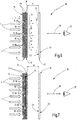
- the darkening surface 11 has two darkening layers 11a which can be displaced relative to one another in relation to the viewing direction B.
- each darkening layer 11a has at least one passage region 17 and one shielding region 18, which are preferably contoured or designed identically.
- the passage regions 17 can be shifted toward one another in coincidence or in such a way that the passage region 17 of one darkening layer 11a coincides with the screening region 18 of the other darkening layer 11 (FIG. FIG. 7 ).
- the arrangement 10 can be used for complete shading or darkening. If the passage regions 17, that is to say the recesses 19, for example, at least partly overlap the two darkening layers 11a, a light effect 26 can be produced ( FIG. 6 ).
- This embodiment can be realized by a roller blind arrangement 30 ( FIG. 8 ).
- a third blind 40 may be present.
- On the third roller blind 40 a darkening layer 11a is wound, while on the first roller blind 32, the respective other darkening layer 11a is wound.
- One of the two darkening layers 11a may be as in FIG. 8 illustrated connected to the divergence sheet 12.
- the two darkening layers 11a may be associated with a common tension rod 34, and separate tension rods 34 may be provided for each roller blind 32, 40. Otherwise, the roller blind arrangement 30 corresponds to FIG FIG. 8 the roller blind assembly 30 from FIG. 4 so that reference may be made to the above description.
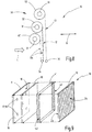
- the distance A between the effect surface structure 13 and the darkening surface 11 or the optional divergence surface 12 is formed by an air gap.
- the connection layer 41 may, for example, for those of the Be made light source L originating light wavelength or the light wavelength range transparent material.
- the bonding layer 41 is transparent to all light wavelengths of visible light.
- FIG. 9 schematically illustrates that one or more peripheral areas, such as the visible light edge surfaces 42, are rendered opaque or at least substantially impermeable. Thereby, an intrusion of stray light into the area between the effect sheet 13 and the divergence sheet 12 or the darkening sheet 11 can be reduced or prevented.
- roller blind assembly 30 or on the pleat assembly 35, 36 can be used to prevent the ingress of interfering light in this area.
- Such means may be arranged, for example, on a guide device for guiding a tension rod 34 of a roller blind or a plisse.
- the fabrics 11, 12, 13 in displaceable and / or pivotable Be held in a frame.
- the darkening sheet 11 may also be formed by a conventional sipe roller blind, wherein the slot openings present there represent the passage areas 17.
- the desired effect surface structure 13 can be introduced by a roller blind, pleated or the like on the window to produce a desired light effect 26.
- the Divergenzvidgesente 12 may consist of several individual strips which are glued to the slot openings in the shutter.
- the diverging sheet 12 consists of several parts, each part being associated with a passage area 17.
- the parts may be directly connected to each other or separately connected to the blackout sheet 11 so that there is only an indirect connection between the parts.
- the invention relates to an arrangement 10 for generating a light effect 26 on a viewing side 24 of an effect surface structure 13.
- a darkening sheet 11 and preferably a divergence sheet 12 is arranged at a distance from the rear side 23 facing away from the viewing side 24.
- the darkening sheet 11 has at least one passage area 17 and at least one shielding area 18.
- L strikes the darkening surface 11 and is at least greatly reduced or completely shielded in the at least one shielding region 18.
- the light L can pass through the at least one passage region 17.
- divergent light beams LD are generated at the respective passband 17, which impinge on the back 23 of the effect surface structure 13 and produce a light effect 26 for a viewer 25 with a view of the viewing side 24.
Landscapes
- Engineering & Computer Science (AREA)
- General Engineering & Computer Science (AREA)
- Architecture (AREA)
- Civil Engineering (AREA)
- Structural Engineering (AREA)
- Blinds (AREA)
- Illuminated Signs And Luminous Advertising (AREA)
- Laminated Bodies (AREA)
- Non-Portable Lighting Devices Or Systems Thereof (AREA)
- Curtains And Furnishings For Windows Or Doors (AREA)
- Operating, Guiding And Securing Of Roll- Type Closing Members (AREA)
Description
Die Erfindung betrifft eine Anordnung zur Erzeugung von Lichteffekten. Eine solche Anordnung ist beispielsweise aus
Solche Anordnungen werden beispielsweise mit Hilfe von Leuchtdioden oder anderen Lichtquellen beleuchtet. Sie können zu dekorativen Zwecken verwendet werden.Such arrangements are illuminated, for example, by means of light-emitting diodes or other light sources. They can be used for decorative purposes.
Aus
Ausgehend hiervon kann es als Aufgabe der vorliegenden Erfindung angesehen werden, die Funktionalität einer Anordnung zur Erzeugung von Lichteffekten zu erhöhen.Based on this, it can be regarded as an object of the present invention to increase the functionality of a device for generating light effects.
Diese Aufgabe wird durch eine Anordnung mit den Merkmalen des Patentanspruches 1 gelöst.This object is achieved by an arrangement having the features of
Erfindungsgemäß weist die Anordnung mehrere in Betrachtungsrichtung eines Betrachters zumindest teilweise überlappend angeordnete Flächengebilde auf. Die Betrachtungsrichtung ist im Wesentlichen rechtwinklig zur Erstreckungsebene der Flächengebilde ausgerichtet.According to the invention, the arrangement has a plurality of webs arranged at least partially overlapping in the viewing direction of a viewer. The viewing direction is oriented substantially perpendicular to the plane of extent of the sheets.
Die Anordnung weist ein Verdunkelungsflächengebilde auf. Das Verdunkelungsflächengebilde weist eine Lichteinfallseite und eine Lichtaustrittseite auf. Die Lichteinfallseite ist einer künstlichen oder natürlichen Lichtquelle zugewandt. Das Verdunkelungsflächengebilde hat wenigstens einen Durchlassbereich und wenigstens einen Abschirmbereich. Das auf das Verdunkelungsflächengebilde auf der Lichteinfallseite auftreffende Licht gelangt zumindest durch den wenigstens einen Durchlassbereich hindurch und tritt aus dem Durchlassbereich an der Lichtaustrittsseite aus. Der wenigstens eine Abschirmbereich kann das Licht nahezu vollständig abschirmen. Im Abschirmbereich kann das Verdunkelungsflächengebilde die Anforderungen an ein sogenanntes "Black-out-Material" erfüllen. Zumindest ist die Intensität des an der Lichtaustrittsseite austretenden Lichts im Durchlassbereich größer als im Abschirmbereich, so dass eine ausreichende Intensitätsdifferenz des Lichts zwischen dem dunkleren Abschirmbereich und dem helleren Durchlassbereich auf der Lichtaustrittsseite gewährleistet ist. Bei einem bevorzugten Ausführungsbeispiel ist das Verdunkelungsflächengebilde durch ein Black-out-Flächengebilde hergestellt, wobei der wenigstens eine Durchlassbereich durch Aussparungen zumindest in der wenigstens einen Verdunkelungslage des Verdunkelungsflächengebildes gebildet ist.The assembly has a blackout sheet. The darkening sheet has a light incident side and a light emission side. The light incident side faces an artificial or natural light source. The darkening sheet has at least one passage area and at least one shielding area. The light incident on the shading sheet on the light incident side passes at least through the at least one passage area and exits from the passage area on the light exit side. The at least one shielding area can almost completely shield the light. In the shielding area, the blackout sheet can meet the requirements of a so-called "black-out material". At least the intensity of the light emerging at the light exit side in the passband is greater than in the shielding region, so that a sufficient intensity difference of the light between the darker shielding region and the brighter passage region on the light exit side is ensured. In a preferred embodiment, the blackout sheet is formed by a black-out sheet, wherein the at least one through-band extends through recesses at least in the at least one blackout sheet of the blackout sheet is formed.
Der wenigstens eine Durchlassbereich kann eine beliebige Gestalt oder Form aufweisen. Auf diese Weise können ein oder mehrere Durchlassbereiche ein Logo, einen Schriftzug, ein Muster oder dergleichen bilden. Es kann auch zur ästhetischen Raumgestaltung verwendet werden. Vorzugsweise ist die gesamte Fläche des einen Durchlassbereichs oder der mehrere Durchlassbereiche zumindest um den Faktor 10 kleiner als die gesamte übrige Fläche des wenigstens einen Abschirmbereichs.The at least one passage region may have any shape or form. In this way, one or more passbands may form a logo, lettering, pattern, or the like. It can also be used for aesthetic interior design. Preferably, the total area of the one or more passage areas is at least a factor of 10 smaller than the entire remaining area of the at least one shielding area.
Zur Erzeugung eines Lichtmusters weist die Anordnung außerdem ein Effektflächengebilde auf. Damit kann für einen Betrachter an einer Betrachtungsseite des Effektflächengebildes ein insbesondere dreidimensionaler Lichteffekterzeugt werden. Das Effektflächengebilde ist aus einem Textilmaterial, vorzugsweise einem Gewebe, hergestellt. Durch die Anordnung der Garne bzw. Fäden im Textilmaterial kann der gewünschte Lichteffekt bewirkt werden. Das Effektflächengebilde hat eine dem Verdunkelungsflächengebilde zugewandte Rückseite und eine der Rückseite entgegengesetzte Betrachtungsseite. Das von den Durchlassbereichen des Verdunkelungsflächengebildes austretende Licht trifft auf die Rückseite des Effektflächengebildes auf und wird an den Fäden bzw. Garnen reflektiert und/oder gestreut und/oder gebrochen und/oder gebeugt. Dadurch entsteht in der Betrachtungsrichtung auf der Betrachtungsseite das Lichtmuster bzw. der Lichteffekt.To produce a light pattern, the arrangement also has an effect surface structure. Thus, for a viewer on a viewing side of the effect surface structure, in particular a three-dimensional light effect can be generated. The effect sheet is made of a textile material, preferably a fabric. The arrangement of the yarns or threads in the textile material, the desired light effect can be effected. The effect sheet has a back side facing the darkening sheet and a back side opposite the back side. The light emerging from the passage areas of the darkening sheet strikes the back of the effect sheet and is reflected and / or scattered and / or broken and / or diffracted at the yarns. As a result, the light pattern or the light effect is produced in the viewing direction on the viewing side.
Durch die Ausgestaltung der erfindungsgemäßen Anordnung ist es möglich, auf der Lichteinfallseite des Verdunkelungsflächengebildes andere als punktförmige bzw. hemisphärische Lichtquellen anzuordnen. Das Verdunkelungsflächengebilde wirkt dabei sozusagen als Blende. Es ist somit möglich, auch komplexere Lichtmuster oder Schriftzüge mit Lichteffekten zu erzeugen. Schließlich kann über das Verdunkelungsflächengebilde auch das natürliche Licht, insbesondere Sonnenlicht als Lichtquelle verwendet werden. Die Anordnung weist zusätzlich zu dem Verdunkelungsflächengebilde und dem Effektflächengebilde ein Divergenzflächengebilde auf, um das parallele Sonnenlicht in divergentes Licht umzuwandeln. Über das Divergenzflächengebilde kann somit an dem wenigstens einen Durchlassbereich hemisphärisch abgestrahltes und vorzugsweise annähernd isotropes Licht erzeugt werden. Das Divergenzflächengebilde und das Verdunkelungsflächengebilde erzeugen im wenigstens einen Durchlassbereich sozusagen eine oder mehrere virtuelle punktförmige Lichtquellen. Bei dieser bevorzugten Ausgestaltung eignet sich die Anordnung auch als Sonnenschutz bzw. zur Beschattung und kann mithin in Sonnenrollos, Sonnenschirmen, Verdunkelungsrollos oder dergleichen Einrichtungen verwendet werden.Due to the configuration of the arrangement according to the invention, it is possible on the light incidence side of the blackout sheet to arrange other than point or hemispherical light sources. The blackout area acts as a kind of aperture. It is thus possible to produce more complex light patterns or lettering with light effects. Finally, the natural light, in particular sunlight, can also be used as the light source via the darkening surface. The arrangement includes a divergence sheet in addition to the darkening sheet and the effect sheet to convert the parallel sunlight into divergent light. Thus, hemispherically radiated and preferably approximately isotropic light can be generated at the at least one transmission region via the diverging surface structure. The divergence sheet and the blackout sheet form, as it were, one or more virtual dot-shaped light sources in the at least one passband. In this preferred embodiment, the arrangement is also suitable as a sunscreen or for shading and can therefore be used in sun blinds, umbrellas, blackout blinds or the like facilities.
Vorzugsweise ist die Intensität des durch den wenigstens einen Durchlassbereich hindurchtretenden Lichts mindestens um das 5- bis 10-fache vorzugsweise um das 10- bis 30-fache größer als die Intensität des durch den wenigstens einen Abschirmbereich hindurchtretenden Lichts.Preferably, the intensity of the light passing through the at least one transmission region is at least 5 to 10 times, preferably 10 to 30 times, greater than the intensity of the light passing through the at least one shielding region.
Bei einer bevorzugten Ausführungsform ist das Divergenzflächengebilde zwischen dem Verdunkelungsflächengebilde und dem Effektflächengebilde angeordnet. Alternativ hierzu kann das Divergenzflächengebilde auch Bestandteil des Verdunkelungsflächengebildes sein.In a preferred embodiment, the divergence sheet is disposed between the blackout sheet and the effect sheet. Alternatively, the divergence sheet may also be part of the blackout sheet.
Vorteilhafterweise liegen das Divergenzflächengebilde und das Verdunkelungsflächengebilde flächig aneinander an und sind beispielsweise stoffschlüssig miteinander verbunden. Zur Erzeugung der Lichteffekte ist es vorteilhaft, wenn das das divergente Licht erzeugende Material des Divergenzflächengebildes sehr nahe an dem wenigstens einen Durchlassbereich angeordnet ist. Außerdem ist die Handhabung der Anordnung vereinfacht, wenn das Divergenzflächengebilde und das Verdunkelungsflächengebilde fest miteinander verbunden sind.Advantageously, the divergence sheet and the darkening surface are flat against each other and, for example, are bonded together in a material-locking manner. To generate the light effects, it is advantageous if the divergent light-generating material of the diverging sheet is arranged very close to the at least one passage region. In addition, the handling of the arrangement is simplified when the divergence sheet and the darkening sheet are firmly bonded together.
Das Divergenzflächengebilde kann eine Folie und/oder Fasermaterial und/oder Textilmaterial aufweisen. Beispielsweise kann ein Faser- oder Vliesmaterial mit einem ausreichenden Faserabstand zur Streuung des im Wesentlichen parallelen Lichts verwendet werden.The divergent sheet may comprise a film and / or fibrous material and / or textile material. For example, a fibrous or nonwoven material having sufficient fiber spacing may be used to diffuse the substantially parallel light.
Das Verdunkelungsflächengebilde und/oder das Divergenzflächengebilde und/oder das Effektflächengebilde können jeweils aus einer oder mehreren aneinander anliegenden Lagen bestehen. Dadurch ist es beispielsweise möglich, das Verdunkelungsflächengebilde derart auszugestalten, dass durch die Abschirmbereiche im Wesentlichen kein Licht hindurchtreten kann. Ein mehrlagiges Effektflächengebilde kann zur Erzielung der gewünschten Lichteffekte bzw. Lichtmuster vorteilhaft sein.The blackout sheet and / or divergence sheet and / or effect sheet may each consist of one or more adjacent layers. As a result, it is possible, for example, to configure the darkening surface in such a way that substantially no light can pass through the shielding regions. A multilayer effect surface may be advantageous for achieving the desired light effects or light patterns.
Bei einem bevorzugten Ausführungsbeispiel weist das Verdunkelungsflächengebilde eine Trägerlage auf, die beispielsweise aus einem Folienmaterial und/oder oder einem Fasermaterial und/oder einem Textilmaterial bestehen kann. Auf dieser Trägerlage ist wenigstens eine Verdunkelungslage angeordnet. Insbesondere können auf beiden Seiten der Trägerlage jeweils eine oder mehrere Verdunkelungslagen angeordnet sein.In a preferred embodiment, the blackout sheet has a backing layer which may be, for example, a sheet material and / or a fibrous material and / or a textile material. On this carrier layer is at least one darkening position arranged. In particular, one or more blackout layers can be arranged on both sides of the carrier layer.
Der wenigstens eine Durchlassbereich kann durch eine Durchbrechung im Verdunkelungsflächengebilde gebildet sein, die sämtliche Lagen des Verdunkelungsflächengebildes ausspart. Es ist alternativ hierzu auch möglich, dass im Durchlassbereich die Trägerlage erhalten bleibt und lediglich die darauf angeordneten Verdunkelungslagen ausgespart sind. Dabei kann die Trägerlage als Divergenzlage und mithin zur Erzeugung des divergenten Lichts dienen. Die Trägerlage kann somit Bestandteil des Divergenzflächengebildes sein oder das Divergenzflächengebilde bilden.The at least one passage region may be formed by an aperture in the blackout sheet which eliminates all layers of the blackout sheet. As an alternative to this, it is also possible for the carrier layer to be retained in the passage region and only the darkening layers arranged thereon are left out. The carrier layer can serve as a divergence layer and thus for generating the divergent light. The carrier layer can thus be part of the divergence sheet or form the divergent sheet.
Bei einem bevorzugten Ausführungsbeispiel ist das Verdunkelungsflächengebilde und/oder das Effektflächengebilde auf jeweils einer Wickelwelle auf- und abwickelbar. Alternativ hierzu können das Verdunkelungsflächengebilde und/oder das Effektflächengebilde als Plissee ausgeführt sein und ziehharmonikaähnlich zusammengeschoben bzw. auseinandergezogen werden. Dabei ist es - wie oben erwähnt - möglich, dass das Divergenzflächengebilde fest und flächig mit dem Verdunkelungsflächengebilde verbunden ist.In a preferred embodiment, the blackout sheet and / or the effect sheet is wound up and unwound on a respective winding shaft. Alternatively, the darkening sheet and / or the effect sheet can be made as a pleat and be pulled or pulled apart like an accordion. It is possible - as mentioned above - that the Divergenzflächengebilde is firmly and extensively connected to the blackout sheet.
Der Abstand zwischen dem Verdunkelungsflächengebilde und dem Effektflächengebilde bzw. zwischen dem Verdunkelungsflächengebilde und dem Divergenzflächengebilde kann durch einen Luftspalt und/oder durch eine Verbindungslage gebildet sein. Die Verbindungslage besteht zumindest in dem Bereich, in dem sich das Licht von dem wenigstens einen Durchlassbereich bzw. dem Divergenzflächengebilde bis zur Rückseite des Effektflächengebildes ausbreitet, aus für die verwendete Lichtwellenlänge bzw. den verwendeten Lichtwellenlängenbereich transparentem Material.The distance between the blackout sheet and the effect sheet or between the blackout sheet and the diverging sheet may be formed by an air gap and / or by a bonding layer. The connection layer consists, at least in the region in which the light propagates from the at least one passage region or the divergence surface to the rear side of the effect surface, for the used light wavelength or the wavelength range of light used transparent material.
Zur Vermeidung der Einstrahlung von störendem Licht kann die Verbindungslage zumindest an einer oder an mehreren Randbereichen soweit technisch möglich lichtundurchlässig ausgeführt sein. Die Verbindungslage kann das Effektflächengebilde mit dem Divergenzflächengebilde bzw. dem Verdunkelungsflächengebilde auch lediglich lokal zur Vorgabe des Abstandes verbinden.In order to avoid the irradiation of interfering light, the connecting layer can be embodied, as far as is technically possible, opaque to light, at least at one or more edge regions. The connection layer can also connect the effect surface structure with the Divergenzflächengebilde or the blackout sheet only locally to specify the distance.
Das Verdunkelungsflächengebilde und das Effektflächengebilde können gemeinsam oder jeweils einen Zugstab aufweisen, der in einer Führungseinrichtung verschiebbar geführt ist. Diese Ausführung kann beispielsweise verwendet werden, wenn das Verdunkelungsflächengebilde und/oder das Effektflächengebilde als Rollo oder als Plissee ausgeführt sind.The darkening sheet and the effect sheet may together or in each case comprise a tension rod, which is displaceably guided in a guide device. This embodiment may be used, for example, when the blackout sheet and / or the effect sheet is made as a blind or pleated.
Bei einem Ausführungsbeispiel weist das Verdunkelungsflächengebilde zwei relativ zueinander verschiebbare Verdunkelungslagen auf, die jeweils wenigstens einen Durchlassbereich und wenigstens einen Abschirmbereich aufweisen. Vorzugsweise sind die Durchlassbereiche und Abschirmbereiche identisch ausgestaltet bzw. konturiert. Durch eine Relativverschiebung der beiden Verdunkelungslagen kann somit eine vollständige Verdunkelung erreicht werden, wenn der Durchlassbereich der einen Verdunkelungslage mit dem Abschirmbereich der jeweils anderen Verdunkelungslage zur Deckung gelangt. Umgekehrt kann ein maximaler Lichtdurchtritt durch die Durchlassbereiche erreicht werden, wenn sich die beiden Durchlassbereiche der beiden Verdunkelungslagen vollständig decken. Durch diese Ausgestaltung kann die Größe und/oder Form des für den Lichtdurchtritt zur Verfügung stehenden Überdeckungsbereichs zwischen den beiden Durchlassbereichen der beiden Verdunkelungslagen insbesondere stufenlos eingestellt werden.In one embodiment, the blackout sheet has two mutually displaceable blackout layers, each having at least one passage area and at least one shielding area. Preferably, the passage areas and shielding areas are configured identically or contoured. By means of a relative displacement of the two darkening layers, a complete darkening can thus be achieved if the passage region of one darkening layer coincides with the shielding region of the other darkening layer. Conversely, a maximum passage of light through the passbands can be achieved if the two passbands of the two blackout layers completely cover each other. By this configuration, the size and / or shape of the light passage available standing coverage area between the two passages of the two blackout layers are particularly adjusted continuously.
Vorteilhafte Ausgestaltungen der Erfindung ergeben sich aus den abhängigen Patentansprüchen, der Beschreibung und der Zeichnung.Advantageous embodiments of the invention will become apparent from the dependent claims, the description and the drawings.
Nachfolgend werden bevorzugte Ausführungsbeispiele der Erfindung anhand der beigefügten Zeichnung im Einzelnen erläutert. Es zeigen:
-
Figur 1 -
Figur 2 ein Ausführungsbeispiel eines Verdunkelungsflächengebildes und eines Divergenzflächengebildes in schematischer Querschnittsansicht, -
Figur 3 ein weiteres Ausführungsbeispiel eines Verdunkelungsflächengebildes in schematischer Querschnittsansicht, -
Figur 4 ein Ausführungsbeispiel der Anordnung als Doppelrollo in schematischer Darstellung, -
Figur 5 ein Ausführungsbeispiel der Anordnung als Faltenrollo in schematischer Darstellung, -
Figuren 6 und 7 ein abgewandeltes Ausführungsbeispiele der Anordnung in einer blockschaltbildähnlichen, schematischen Darstellung mit zwei gegeneinander verschiebbaren Verdunkelungslagen, -
Figur 8 ein Ausführungsbeispiel der Anordnung gemäß derFiguren 6 und 7 als Rollo in schematischer Darstellung und -
Figur 9 eine schematische Explosionsdarstellung eines Ausführungsbeispiels der Anordnung mit einer Verbindungslage zwischen einem Effektflächengebilde und einem Divergenzflächengebilde.
-
FIG. 1 a block diagram similar, schematic representation of an embodiment of the arrangement, -
FIG. 2 an embodiment of a blackout sheet and a Divergenzflächengebildes in a schematic cross-sectional view, -
FIG. 3 a further embodiment of a blackout sheet in a schematic cross-sectional view, -
FIG. 4 an embodiment of the arrangement as a double roller blind in a schematic representation, -
FIG. 5 an embodiment of the arrangement as a roller blind in a schematic representation, -
FIGS. 6 and 7 a modified embodiment of the arrangement in a block diagram similar, schematic representation with two mutually displaceable blackout layers, -
FIG. 8 an embodiment of the arrangement according to theFIGS. 6 and 7 as a roller blind in a schematic representation and -
FIG. 9 a schematic exploded view of an embodiment of the arrangement with a connection layer between an effect sheet and a Divergenzflächengebilde.
In
Die Anordnung 10 weist ein Verdunkelungsflächengebilde 11, ein Divergenzflächengebilde 12 und ein Effektflächengebilde 13 auf. Das Verdunkelungsflächengebilde 11 hat eine Lichteinfallseite 15 und eine entgegengesetzte Lichtaustrittsseite 16. Es weist wenigstens ein Durchlassbereich 17 wenigstens einen Abschirmbereich 18 auf. Das Licht L, das von einer künstlichen oder natürlichen Lichtquelle emittiert wird und auf die Lichteinfallseite 15 des Verdunkelungsflächengenbildes 11 auftrifft gelangt zumindest durch den wenigstens einen Durchlassbereich 17 durch das Verdunkelungsflächengebilde 11 hindurch und tritt auf der Lichtaustrittsseite 16 aus. Das Verdunkelungsflächengebilde 11 ist dabei derart ausgestaltet, dass die Intensitätsminderung des an der Lichteinfallseite 15 auftreffenden Lichts in dem wenigstens einen Abschirmbereich 18 deutlich größer und beispielsgemäß mindestens zehnmal größer ist als die Intensitätsminderung des durch den wenigstens einen Durchlassbereich 17 hindurchtretenden Lichts.The
Bei dem hier veranschaulichten, bevorzugten Ausführungsbeispiel der Anordnung 10 wird in dem wenigstens einen Abschirmbereich 18 das einfallende Licht L nahezu vollständig abgeschirmt, so dass durch den Abschirmbereich 18 nur ein vernachlässigbarer Lichtanteil hindurchtreten kann. Das Verdunkelungsflächengebilde 11 ist vorzugsweise in dem wenigstens einen Abschirmbereich 18 derart aufgebaut, dass es die Voraussetzungen für ein sogenanntes "Black-out"-Material erfüllt. Der wenigstens eine Durchlassbereich 17 ist durch jeweils eine Aussparung 19 in dem Verdunkelungsflächengebilde 11 gebildet, so dass das Licht L dort ungehindert von der Lichteinfallseite 15 zur Lichtaustrittsseite 16 hindurchgehen kann.In the preferred embodiment of the
Bei den veranschaulichten Ausführungsbeispielen sind mehrere Aussparungen 19 in Form von zylindrischen Löchern im Verdunkelungsflächengebilde 11 vorhanden. Die Form bzw. Kontur der Aussparungen kann abweichend von einem kreisrunden Querschnitt auch beliebig anders gewählt werden. Die Gesamtquerschnittsfläche des Aussparungen 19 ist kleiner und vorzugsweise um mindestens den Faktor 10 kleiner als die gesamte Fläche des die Aussparungen 19 umgebenden Abschirmbereichs 18. Außerdem ist es beispielsgemäß vorgesehen, dass die Distanz D zwischen zwei unmittelbar benachbarten Aussparungen 19 in einer Raumrichtung, in der sich das Verdunkelungsflächengebilde 11 erstreckt, größer und vorzugsweise mindestens zweimal so groß ist wie die Abmessung der Aussparung 19 in dieser Raumrichtung.In the illustrated embodiments, a plurality of recesses 19 are provided in the form of cylindrical holes in the darkening
Bei dem Ausführungsbeispiel des Verdunkelungsflächengebildes 11 gemäß
Zur Herstellung des Verdunkelungsflächengebildes 11 wird die Trägerschicht 11b bereitgestellt. Die Trägerschicht kann vorzugsweise ein Textilmaterial sein, beispielsweise ein Gewebe oder auch eine Maschenware. Auf die Trägerlage 11b werden anschließend eine oder mehrere Verdunkelungslagen 11a auf einer oder auf beiden Seiten aufgebracht. Die Verdunkelungslagen 11a stehen vorzugsweise aus einem Kunststoffmaterial. Die Anzahl und die Dicke der Verdunkelungslagen wird so gewählt, dass die in dem Abschirmbereich 18 geforderte Abschirmwirkung für das einfallende Licht L erzielt wird.To produce the
Zur Herstellung der Aussparungen 19 können anschließend, wie schematisch in
Alternativ hierzu ist es auch möglich, beim Beschichten der Trägerlage 11b den wenigstens einen Durchlassbereich 17 derart zu maskieren, dass in den aufgebrachten Verdunkelungslagen 11a die Aussparungen 19 entstehen (
Das Divergenzflächengebilde 12 dient dazu, paralleles Licht L zu streuen und im Bereich der Lichtaustrittsseite 16 an dem wenigstens einen Durchlassbereich 17 divergente Lichtstrahlen LD zu erzeugen. Sind die Durchlassbereiche 17 bzw. Aussparungen 19 im Querschnitt ausreichend klein, so entsteht auf der Lichtaustrittsseite 16 an jeder Aussparung 19 in Kombination mit den Divergenzflächengebilde 12 ein virtuelle punktförmige Lichtquelle, die divergenten Lichtstrahlen LD hemisphärisch und vorzugsweise soweit technisch möglich isotrop abstrahlt.The
Das Divergenzflächengebilde 12 kann eine Folie und/oder ein Textilmaterial und/oder ein Fasermaterial sein und beispielsweise als Gewebe, Maschenware, Vliesstoff oder Zellstoff ausgeführt sein. Vorzugsweise ist das Divergenzflächengebilde 12 flächig und fest mit dem Verdunkelungsflächengebilde 11 verbunden. Es kann beispielsweise unmittelbar auf der Lichtaustrittsseite 16 des Verdunkelungsflächengebildes 11 angeordnet sein (
Das Verdunkelungsflächengebilde 11 hat somit die Funktion einer Art Blende und erzeugt an dem wenigstens einen Durchlassbereich 17 gemeinsam mit dem Divergenzflächengebilde 12 die divergenten Lichtstrahlen LD. Die divergenten Lichtstrahlen LD treffen auf das Effektflächengebilde 13 auf, das mit Abstand A zum Divergenzflächengebilde 12 angeordnet ist. Das Effektflächengebilde 13 hat eine Rückseite 23, die dem Divergenzflächengebilde 12 bzw. der Lichtaustrittsseite 16 des Verdunkelungsflächengebildes 11 zugewandt ist. Die divergenten Lichtstrahlen LD treffen auf dieser Rückseite 23 auf. Entgegengesetzt zur Rückseite 23 hat das Effektflächengebilde 13 eine Betrachtungsseite 24. Die Betrachtungsseite 24 ist einem Betrachter 25 zugewandt.The darkening
Das Effektflächengebilde 13 weist vorzugsweise ein Textilmaterial und/oder ein Fasermaterial und/oder ein Folienmaterial auf. Beispielsweise kann das Effektflächengebilde 13 aus einem oder mehreren Garnen hergestellt sein, beim Ausführungsbeispiel als Gewebe. Die divergenten Lichtstrahlen LD treffen auf der Rückseite 23 auf und werden zumindest teilweise durch das Effektflächengewebe und beispielsgemäß an betreffenden Garnabschnitten gestreut und/oder reflektiert und/oder gebrochen. Durch die Garnkonstruktion und/oder die Anordnung der Garne relativ zueinander kann ein vorgegebener, gewünschter Lichteffekt für den Betrachter 25 erzeugt werden. Insbesondere kann ein dreidimensionaler Lichteffekt 26 entstehen. Abhängig vom Aufbau des Effektflächengewebes 13 bestehen hierbei eine Vielzahl von Möglichkeiten. Beispielsweise können um die virtuellen Lichtquellen an den Aussparungen 19 sternförmige Strahlen erzeugt werden, die sich für den Betrachter 25 auch aus der Ebene des Effektflächengebildes 13 nach hinten in den Raum erstrecken. Auch Ellipsen- oder Linienmuster lassen sich erzeugen.The
Dieser räumliche Effekt entsteht nur dann, wenn das auf die Rückseite 23 auftreffende Licht divergent ist. Die erfindungsgemäße Anordnung 10 kann mit beliebigen, natürlichen oder künstlichen Lichtquellen arbeiten. Beispielsweise ist das auf der Erde auftreffende Sonnenlicht parallel, so dass durch das Effektflächengebilde 13 kein Lichteffekt erzeugt werden könnte. Die Anordnung 10 erzeugt aus dem parallelen Licht L die divergenten Lichtstrahlen LD und kann somit auch bei Sonnenlicht einen Lichteffekt 26 erzeugen. Die Anordnung 10 eignet sich daher zur Verwendung bei Sonnenschutzeinrichtungen oder Beschattungseinrichtungen, wie etwa Sonnenschirmen, Sonnensegeln, Rollos oder dergleichen. So kann beispielsweise bei der Verdunkelung eines Raumes am Tag dennoch ein besonderer Lichteffekt an den verdunkelten Fenstern erzeugt werden.This spatial effect arises only when the incident on the back 23 light is divergent. The
Es ist in Abwandlung zu den hier veranschaulichten Ausführungsbeispielen auch möglich, einen Teil eines Durchlassbereichs 17 bzw. einen oder mehrere der Durchlassbereiche 17 nicht durch das Divergenzflächengebilde 12 abzudecken. Dies kann beispielsweise dadurch bewirkt werden, dass in dem Divergenzflächengebilde 12 ebenfalls eine Aussparung 19 vorgesehen wird. Das Licht wird durch diese Aussparungen dann parallel hindurch auf das Effektflächengebilde 13 auftreffen. Dies kann beispielsweise dazu verwendet werden, Schriftzüge oder Firmenlogos ohne Lichteffekt scharf abzubilden.It is also possible, as a modification to the embodiments illustrated here, to cover part of a passage region 17 or one or more of the passage regions 17 by the
Wenn die Anordnung 10 mit einer Lichtquelle betrieben wird, die anstelle von parallelem Licht L divergentes Licht erzeugt, kann das Divergenzflächengebilde 12 auch entfallen.When the
In den
In
In den
Diese Ausgestaltung kann durch eine Rolloanordnung 30 realisiert werden (
Es ist schließlich auch möglich, die Anordnung 10 mit zwei zueinander verschiebbaren Verdunkellungslagen 11a durch Plissees auszuführen. In Abwandlung zu dem in
Bei den bislang beschriebenen Ausführungsbeispielen ist zwischen dem Effektflächengebilde 13 und dem Verdunkelungsflächengebilde 11 bzw. dem optionalen Divergenzflächengebilde 12 der Abstand A durch einen Luftspalt gebildet. Es ist in Abwandlung hierzu bei allen Ausführungsbeispielen möglich, zwischen dem Effektflächengebilde 13 und dem Divergenzflächengebilde 12 bzw. dem Verdunkelungsflächengebilde 11 eine Verbindungslage 41 anzuordnen. Die Verbindungslage 41 kann beispielsweise aus für die von der Lichtquelle L stammenden Lichtwellenlänge bzw. dem Lichtwellenlängenbereich transparente Material hergestellt sein. Vorzugsweise ist die Verbindungslage 41 für alle Lichtwellenlängen des sichtbaren Lichts durchlässig. Es ist allerdings auch möglich, die Verbindungslage 41 zur Einstellung einer gewünschten Lichtfarbe als Farbfilter auszuführen.In the exemplary embodiments described so far, the distance A between the
Wie in
Es ist ferner möglich, anstelle von Rollos oder Plissees andere mechanische Vorrichtungen für die Flächengebilde 11, 12, 13 zu verwenden. Beispielsweise können die Flächengebilde 11, 12, 13 in verschiebbaren und/oder verschwenkbarem Rahmen gehalten werden. Das Verdunkelungsflächengebilde 11 kann auch von einem herkömmlichen Lamellenrolladen gebildet sein, wobei die dort vorhandenen Schlitzöffnungen die Durchlassbereiche 17 darstellen. Das gewünschte Effektflächengebilde 13 kann durch ein Rollo, Plissee oder dergleichen am Fenster eingebracht werden, um einen gewünschten Lichteffekt 26 zu erzeugen. Das Divergenzflächengebilde 12 kann dabei aus mehreren einzelnen Streifen bestehen, die auf die Schlitzöffnungen im Rolladen geklebt werden.It is also possible to use other mechanical devices for the
In Abwandlung zu den beschriebenen Ausführungsbeispielen ist es möglich, dass das Divergenzflächengebilde 12 aus mehreren Teilen besteht, wobei jeder Teil einem Durchlassbereich 17 zugeordnet ist. Die Teile können unmittelbar miteinander verbunden sein oder separat mit dem Verdunkelungsflächengebilde 11 verbunden sein, so dass zwischen den Teilen lediglich eine mittelbare Verbindung besteht.In a modification of the described embodiments, it is possible that the diverging
Die Erfindung betrifft eine Anordnung 10 zur Erzeugung eines Lichteffekts 26 auf einer Betrachtungsseite 24 eines Effektflächengebildes 13. Hierfür ist mit Abstand auf einer der Betrachtungsseite 24 abgewandten Rückseite 23 zum Effektflächengebilde 13 ein Verdunkelungsflächengebilde 11 sowie vorzugsweise ein Divergenzflächengebilde 12 angeordnet. Das Verdunkelungsflächengebilde 11 weist wenigsten einen Durchlassbereich 17 und wenigstens einen Abschirmbereich 18 auf. Auf der dem Effektflächengebilde 13 abgewandten Lichteinfallseite 15 trifft L auf das Verdunkelungsflächengebilde 11 auf und wird in dem wenigstens einen Abschirmbereich 18 zumindest stark gemindert oder vollständig abgeschirmt. Das Licht L kann durch den wenigstens einen Durchlassbereich 17 hindurchtreten. Mittels dem Divergenzflächengebilde 12 werden divergente Lichtstrahlen LD an dem jeweiligen Durchlassbereich 17 erzeugt, die auf die Rückseite 23 des Effektflächengebildes 13 auftreffen und für einen Betrachter 25 mit Blick auf die Betrachtungsseite 24 einen Lichteffekt 26 erzeugen.The invention relates to an
- 1010
- Anordnungarrangement
- 1111
- VerdunkelungsflächengebildeBlackout fabrics
- 11a11a
- Verdunkelungslageblackout situation
- 11b11b
- Trägerlagesupport layer
- 1212
- DivergenzflächengebildeDivergence sheet
- 1313
- EffektflächengebildeEffect fabrics
- 1515
- LichteinfallseiteIncident light side
- 1616
- LichtaustrittsseiteLight output side
- 1717
- DurchlassbereichPassband
- 1818
- Abschirmbereichshielding
- 1919
- Aussparungrecess
- 2323
- Rückseiteback
- 2424
- Betrachtungsseiteviewing side
- 2525
- Betrachterobserver
- 2626
- Lichteffektlight effect
- 3030
- Doppelrollodouble blind
- 3131
- Wickelwellewinding shaft
- 3232
- erstes Rollofirst roller blind
- 3333
- zweites Rollosecond roller blind
- 3434
- Zugstabtension rod
- 3535
- erstes Plisseefirst pleated
- 3636
- zweites Plisseesecond pleated
- 3737
- Führungseinrichtungguide means
- 4040
- drittes Rollothird blind
- 4141
- Verbindungslageconnecting layer
- 4242
- Kantenflächeedge surface
- AA
- Abstanddistance
- BB
- Betrachtungsrichtungviewing direction
- DD
- Distanzdistance
- LL
- Lichtlight
- LDLD
- divergente Lichtstrahlendivergent rays of light
Claims (13)
- Arrangement (10) for generating a light effect (26),
with several surface structures (11, 12, 13) arranged at least partially overlapping in an observation direction (B),
with a darkening surface structure (11) which has a light incidence side (15) and a light emergence side (16), and which comprises at least one passage region (17) and at least one screening region (18), wherein the light (L) hitting the light incidence side (15) passes at least partially through the at least one passage region (17) and emerges on the light emergence side (16),
wherein the intensity reduction of the light (L) hitting the at least one screening region (18) on the light incidence side (15) is greater than the intensity reduction of the light (L) hitting the at least one passage region (17),
with at least one effect surface structure (11) made of a textile material which comprises a back side (23) facing the light emergence side (16) of the darkening surface structure (11) and an observation side (24), wherein the effect surface structure (13) is arranged at a distance from the darkening surface structure (11), and wherein the light hitting the back side (23) is at least partially reflected and/or scattered and or refracted and/or bent, and emerges at least partially at the observation side (24),
with a divergence surface structure (12) which is configured to convert at least substantially parallel incident light (L) into divergent light (LD),
characterised in that the divergence surface structure (12) comprises a film material and/or fibre material and/or textile material. - Arrangement according to claim 1, characterised in that the at least one passage region (17) is formed by an opening (19) in the darkening surface structure (11).
- Arrangement according to claim 1 or 2, characterised in that the at least one screening region (18) screens out the incident light substantially completely.
- Arrangement according to any of the preceding claims, characterised in that the intensity of the light passing through the at least one passage region (17) is at least 5 times to 10 times, or 10 times to 30 times greater than the intensity of the light passing through the at least one screening region (18).
- Arrangement according to any of the preceding claims, characterised in that the divergence surface structure (12) is arranged between the darkening surface structure (11) and the effect surface structure (13).
- Arrangement according to any of the preceding claims, characterised in that the divergence surface structure (12) and the darkening surface structure (11) adjoin each other.
- Arrangement according to any of the preceding claims, characterised in that the darkening surface structure (11) consists of several layers (11a, 11b) lying on each other superficially.
- Arrangement according to claim 7, characterised in that the darkening surface structure (11) has a carrier layer (11b) on which at least one darkening layer (11a) is arranged.
- Arrangement according to claim 8, characterised in that the carrier layer (11b) extends only in at least one screening region (18) and leaves the at least one passage region (17) clear.
- Arrangement according to claim 8, characterised in that the carrier layer (11b) extends into the at least one passage region (17) and forms at least one layer of the divergence surface structure (12).
- Arrangement according to any of the preceding claims, characterised in that the darkening surface structure (11) and/or the effect surface structure (13) can each be wound onto and unwound from a winding shaft (31) and/or are folded so they can be drawn together and pulled apart.
- Arrangement according to claim 11, characterised in that the darkening surface structure (11) and/or the effect surface structure (13) each have a pull rod (34) which is guided so as to be movable in at least one guide device (37).
- Arrangement according to any of the preceding claims, characterised in that the darkening surface structure (11) has two darkening layers (11a) which can be moved relative to each other and each have at least one passage region (17) and at least one screening region (18).
Applications Claiming Priority (2)
| Application Number | Priority Date | Filing Date | Title |
|---|---|---|---|
| DE102014106602.2A DE102014106602A1 (en) | 2014-05-12 | 2014-05-12 | Arrangement for generating light effects with shading function |
| PCT/EP2015/057460 WO2015172941A1 (en) | 2014-05-12 | 2015-04-07 | Arrangement for generating light effects having a shadowing function |
Publications (2)
| Publication Number | Publication Date |
|---|---|
| EP3143328A1 EP3143328A1 (en) | 2017-03-22 |
| EP3143328B1 true EP3143328B1 (en) | 2019-06-12 |
Family
ID=52988023
Family Applications (1)
| Application Number | Title | Priority Date | Filing Date |
|---|---|---|---|
| EP15717117.4A Active EP3143328B1 (en) | 2014-05-12 | 2015-04-07 | Arrangement for generating light effects having a shadowing function |
Country Status (8)
| Country | Link |
|---|---|
| US (1) | US10443809B2 (en) |
| EP (1) | EP3143328B1 (en) |
| JP (1) | JP6708628B2 (en) |
| KR (1) | KR102372447B1 (en) |
| CN (1) | CN106461194B (en) |
| DE (1) | DE102014106602A1 (en) |
| TR (1) | TR201909753T4 (en) |
| WO (1) | WO2015172941A1 (en) |
Families Citing this family (9)
| Publication number | Priority date | Publication date | Assignee | Title |
|---|---|---|---|---|
| DE102016202016A1 (en) * | 2016-02-10 | 2017-08-10 | Bos Gmbh & Co. Kg | Shading system for a vehicle interior |
| DE102016107636A1 (en) * | 2016-04-25 | 2017-11-23 | Gebr. Achter GmbH & Co. KG | light installation |
| DE102017215369A1 (en) * | 2017-09-01 | 2019-03-07 | Benecke-Kaliko Ag | Translucent multi-layer composite film |
| DE102018131135A1 (en) | 2018-11-05 | 2020-05-07 | Neutex Home Deco Gmbh | Fabrics, in particular for use as privacy and / or glare protection, and methods for producing a fabric according to the invention |
| CN114599851B (en) * | 2019-10-18 | 2025-01-10 | 亨特道格拉斯公司 | Luminous building structure covering and method of operating the same |
| DE102021116099A1 (en) * | 2020-11-02 | 2022-05-05 | Olsa S.P.A. | AUTOMOTIVE OPTICAL DEVICE, AUTOMOTIVE LAMP AND AMBIENT LIGHT |
| CA3212568A1 (en) | 2021-03-23 | 2022-09-29 | Coty CHURCH | Lighted architectural-structure covering |
| CN113048413B (en) * | 2021-03-24 | 2022-08-05 | 上海莹通照明工程有限公司 | Lighting device convenient to adjust illumination scope |
| US12098819B2 (en) * | 2022-11-21 | 2024-09-24 | Netflix, Inc. | Stage lighting assembly with perforated layer |
Family Cites Families (16)
| Publication number | Priority date | Publication date | Assignee | Title |
|---|---|---|---|---|
| US3961434A (en) * | 1974-11-18 | 1976-06-08 | Everbrite Electric Signs, Inc. | Animated sign |
| US4263737A (en) * | 1980-04-04 | 1981-04-28 | Thomas A. Schutz Co., Inc. | Illuminated grid display with primary and secondary copy |
| NL9300014A (en) * | 1993-01-06 | 1994-08-01 | Ass Marinus T J Van | Translucent screen, building equipped with a translucent screen and working method for screening a room. |
| US5772314A (en) * | 1995-09-15 | 1998-06-30 | Brumer; Daryl J. | Ceiling ornament system |
| DE19946015A1 (en) * | 1999-09-25 | 2001-04-19 | Bayerische Motoren Werke Ag | Device to dim lamp, has two meshes of holes located directly behind one another and sliding relative to one another, lying against each other directly |
| FR2840972A1 (en) * | 2002-06-12 | 2003-12-19 | Marc Fontoynont | LIGHTING AND DECORATION DEVICE |
| DE20300615U1 (en) * | 2003-01-15 | 2003-03-27 | Eschenlohr, Gerda, 81377 München | Electrical lamp shade is produced with elements or pattern that produces lighting efffects |
| JP2005242244A (en) * | 2004-02-27 | 2005-09-08 | Shin Nippon Process Kogeisha:Kk | Display device |
| KR200398864Y1 (en) * | 2005-07-25 | 2005-10-17 | (주)한국윈텍 | Multiblind apparatus having multi-roll unit |
| JP2009540355A (en) * | 2006-06-08 | 2009-11-19 | コーニンクレッカ フィリップス エレクトロニクス エヌ ヴィ | Textile products and methods for manufacturing the same |
| US8021002B2 (en) * | 2006-06-12 | 2011-09-20 | Koninklijke Philips Electronics N.V. | Speckle-generating lighting system for attracting viewer's attention |
| ES2374618T3 (en) | 2009-08-05 | 2012-02-20 | Ettlin Aktiengesellschaft | ARRANGEMENT TO CREATE LIGHT EFFECTS. |
| KR101260120B1 (en) * | 2010-12-09 | 2013-05-02 | (주)엘지하우시스 | Display device having surface material which can display image and method for manufacturing the same |
| JP2012174634A (en) * | 2011-02-24 | 2012-09-10 | Sharp Corp | Light source module and optical member |
| US10132470B2 (en) * | 2011-09-05 | 2018-11-20 | Robe Lighting S.R.O. | Versatile beam and wash optical system for an automated luminaire |
| DE102012215165B4 (en) * | 2012-08-27 | 2020-12-03 | Lisa Dräxlmaier GmbH | Decor composite with dynamic light structures |
-
2014
- 2014-05-12 DE DE102014106602.2A patent/DE102014106602A1/en not_active Ceased
-
2015
- 2015-04-07 TR TR2019/09753T patent/TR201909753T4/en unknown
- 2015-04-07 CN CN201580024787.8A patent/CN106461194B/en active Active
- 2015-04-07 WO PCT/EP2015/057460 patent/WO2015172941A1/en not_active Ceased
- 2015-04-07 JP JP2017512104A patent/JP6708628B2/en active Active
- 2015-04-07 EP EP15717117.4A patent/EP3143328B1/en active Active
- 2015-04-07 US US15/310,619 patent/US10443809B2/en active Active
- 2015-04-07 KR KR1020167033878A patent/KR102372447B1/en active Active
Non-Patent Citations (1)
| Title |
|---|
| None * |
Also Published As
| Publication number | Publication date |
|---|---|
| US10443809B2 (en) | 2019-10-15 |
| JP2017518448A (en) | 2017-07-06 |
| DE102014106602A1 (en) | 2015-11-12 |
| KR102372447B1 (en) | 2022-03-10 |
| CN106461194A (en) | 2017-02-22 |
| EP3143328A1 (en) | 2017-03-22 |
| KR20170008247A (en) | 2017-01-23 |
| CN106461194B (en) | 2020-02-14 |
| TR201909753T4 (en) | 2019-07-22 |
| US20170082259A1 (en) | 2017-03-23 |
| JP6708628B2 (en) | 2020-06-10 |
| WO2015172941A1 (en) | 2015-11-19 |
Similar Documents
| Publication | Publication Date | Title |
|---|---|---|
| EP3143328B1 (en) | Arrangement for generating light effects having a shadowing function | |
| EP2284306B1 (en) | Assembly for creating light effects | |
| DE102013020715B4 (en) | Uniformly luminous textile fabric | |
| WO2012113603A1 (en) | Lighting device | |
| DE19922973A1 (en) | Translucent pane arrangement | |
| WO2021219331A1 (en) | Apparatus for generating a virtual image with interference light suppression | |
| DE102010031192B4 (en) | Lenticular lighting device and control element | |
| WO2011150902A1 (en) | Shading system | |
| DE102016114843A1 (en) | Arrangement with an optical seam and a lighting device, their use and method for producing the arrangement | |
| EP2587134B1 (en) | Lamp | |
| EP3058123B1 (en) | Light deflecting system | |
| WO2016202491A1 (en) | Protection device for a vehicle interior | |
| DE102018208740A1 (en) | Method for generating an interior lighting in the region of a roof opening of a motor vehicle and shading arrangement for carrying out the method | |
| DE102004036649A1 (en) | Window blind with different light transmission | |
| EP2943377B1 (en) | Illumination for the detection of raindrops on a window by means of a camera | |
| EP3239602B1 (en) | Light installation | |
| DE102021100977A1 (en) | Motor vehicle headlights with slats | |
| WO2022262886A1 (en) | Privacy-protecting device | |
| DE102024209470A1 (en) | Lighting equipment, use and vehicle | |
| DE102024206437A1 (en) | Lighting arrangement for the interior of a vehicle and the vehicle having the lighting arrangement | |
| EP0001636B1 (en) | Exposure device for colour enlarging or copying apparatuses | |
| DE3524734C2 (en) | ||
| DE546254C (en) | Drum lock | |
| DE102019103580A1 (en) | LIGHTING DEVICE AND INTERIOR CLADDING OR CLADDING ELEMENT WITH A LIGHTING DEVICE | |
| DE2511574A1 (en) | PROJECTION WALL |
Legal Events
| Date | Code | Title | Description |
|---|---|---|---|
| STAA | Information on the status of an ep patent application or granted ep patent |
Free format text: STATUS: THE INTERNATIONAL PUBLICATION HAS BEEN MADE |
|
| PUAI | Public reference made under article 153(3) epc to a published international application that has entered the european phase |
Free format text: ORIGINAL CODE: 0009012 |
|
| STAA | Information on the status of an ep patent application or granted ep patent |
Free format text: STATUS: REQUEST FOR EXAMINATION WAS MADE |
|
| 17P | Request for examination filed |
Effective date: 20161102 |
|
| AK | Designated contracting states |
Kind code of ref document: A1 Designated state(s): AL AT BE BG CH CY CZ DE DK EE ES FI FR GB GR HR HU IE IS IT LI LT LU LV MC MK MT NL NO PL PT RO RS SE SI SK SM TR |
|
| AX | Request for extension of the european patent |
Extension state: BA ME |
|
| DAV | Request for validation of the european patent (deleted) | ||
| DAX | Request for extension of the european patent (deleted) | ||
| GRAP | Despatch of communication of intention to grant a patent |
Free format text: ORIGINAL CODE: EPIDOSNIGR1 |
|
| STAA | Information on the status of an ep patent application or granted ep patent |
Free format text: STATUS: GRANT OF PATENT IS INTENDED |
|
| INTG | Intention to grant announced |
Effective date: 20190122 |
|
| GRAS | Grant fee paid |
Free format text: ORIGINAL CODE: EPIDOSNIGR3 |
|
| GRAA | (expected) grant |
Free format text: ORIGINAL CODE: 0009210 |
|
| STAA | Information on the status of an ep patent application or granted ep patent |
Free format text: STATUS: THE PATENT HAS BEEN GRANTED |
|
| AK | Designated contracting states |
Kind code of ref document: B1 Designated state(s): AL AT BE BG CH CY CZ DE DK EE ES FI FR GB GR HR HU IE IS IT LI LT LU LV MC MK MT NL NO PL PT RO RS SE SI SK SM TR |
|
| REG | Reference to a national code |
Ref country code: GB Ref legal event code: FG4D Free format text: NOT ENGLISH |
|
| REG | Reference to a national code |
Ref country code: CH Ref legal event code: EP |
|
| REG | Reference to a national code |
Ref country code: AT Ref legal event code: REF Ref document number: 1143026 Country of ref document: AT Kind code of ref document: T Effective date: 20190615 |
|
| REG | Reference to a national code |
Ref country code: CH Ref legal event code: NV Representative=s name: VALIPAT S.A. C/O BOVARD SA NEUCHATEL, CH |
|
| REG | Reference to a national code |
Ref country code: DE Ref legal event code: R096 Ref document number: 502015009315 Country of ref document: DE |
|
| REG | Reference to a national code |
Ref country code: IE Ref legal event code: FG4D Free format text: LANGUAGE OF EP DOCUMENT: GERMAN |
|
| REG | Reference to a national code |
Ref country code: NL Ref legal event code: MP Effective date: 20190612 |
|
| REG | Reference to a national code |
Ref country code: LT Ref legal event code: MG4D |
|
| PG25 | Lapsed in a contracting state [announced via postgrant information from national office to epo] |
Ref country code: LT Free format text: LAPSE BECAUSE OF FAILURE TO SUBMIT A TRANSLATION OF THE DESCRIPTION OR TO PAY THE FEE WITHIN THE PRESCRIBED TIME-LIMIT Effective date: 20190612 Ref country code: FI Free format text: LAPSE BECAUSE OF FAILURE TO SUBMIT A TRANSLATION OF THE DESCRIPTION OR TO PAY THE FEE WITHIN THE PRESCRIBED TIME-LIMIT Effective date: 20190612 Ref country code: NO Free format text: LAPSE BECAUSE OF FAILURE TO SUBMIT A TRANSLATION OF THE DESCRIPTION OR TO PAY THE FEE WITHIN THE PRESCRIBED TIME-LIMIT Effective date: 20190912 Ref country code: SE Free format text: LAPSE BECAUSE OF FAILURE TO SUBMIT A TRANSLATION OF THE DESCRIPTION OR TO PAY THE FEE WITHIN THE PRESCRIBED TIME-LIMIT Effective date: 20190612 Ref country code: HR Free format text: LAPSE BECAUSE OF FAILURE TO SUBMIT A TRANSLATION OF THE DESCRIPTION OR TO PAY THE FEE WITHIN THE PRESCRIBED TIME-LIMIT Effective date: 20190612 Ref country code: AL Free format text: LAPSE BECAUSE OF FAILURE TO SUBMIT A TRANSLATION OF THE DESCRIPTION OR TO PAY THE FEE WITHIN THE PRESCRIBED TIME-LIMIT Effective date: 20190612 |
|
| PG25 | Lapsed in a contracting state [announced via postgrant information from national office to epo] |
Ref country code: BG Free format text: LAPSE BECAUSE OF FAILURE TO SUBMIT A TRANSLATION OF THE DESCRIPTION OR TO PAY THE FEE WITHIN THE PRESCRIBED TIME-LIMIT Effective date: 20190912 Ref country code: GR Free format text: LAPSE BECAUSE OF FAILURE TO SUBMIT A TRANSLATION OF THE DESCRIPTION OR TO PAY THE FEE WITHIN THE PRESCRIBED TIME-LIMIT Effective date: 20190913 Ref country code: RS Free format text: LAPSE BECAUSE OF FAILURE TO SUBMIT A TRANSLATION OF THE DESCRIPTION OR TO PAY THE FEE WITHIN THE PRESCRIBED TIME-LIMIT Effective date: 20190612 Ref country code: LV Free format text: LAPSE BECAUSE OF FAILURE TO SUBMIT A TRANSLATION OF THE DESCRIPTION OR TO PAY THE FEE WITHIN THE PRESCRIBED TIME-LIMIT Effective date: 20190612 |
|
| PG25 | Lapsed in a contracting state [announced via postgrant information from national office to epo] |
Ref country code: EE Free format text: LAPSE BECAUSE OF FAILURE TO SUBMIT A TRANSLATION OF THE DESCRIPTION OR TO PAY THE FEE WITHIN THE PRESCRIBED TIME-LIMIT Effective date: 20190612 Ref country code: SK Free format text: LAPSE BECAUSE OF FAILURE TO SUBMIT A TRANSLATION OF THE DESCRIPTION OR TO PAY THE FEE WITHIN THE PRESCRIBED TIME-LIMIT Effective date: 20190612 Ref country code: PT Free format text: LAPSE BECAUSE OF FAILURE TO SUBMIT A TRANSLATION OF THE DESCRIPTION OR TO PAY THE FEE WITHIN THE PRESCRIBED TIME-LIMIT Effective date: 20191014 Ref country code: CZ Free format text: LAPSE BECAUSE OF FAILURE TO SUBMIT A TRANSLATION OF THE DESCRIPTION OR TO PAY THE FEE WITHIN THE PRESCRIBED TIME-LIMIT Effective date: 20190612 Ref country code: NL Free format text: LAPSE BECAUSE OF FAILURE TO SUBMIT A TRANSLATION OF THE DESCRIPTION OR TO PAY THE FEE WITHIN THE PRESCRIBED TIME-LIMIT Effective date: 20190612 Ref country code: RO Free format text: LAPSE BECAUSE OF FAILURE TO SUBMIT A TRANSLATION OF THE DESCRIPTION OR TO PAY THE FEE WITHIN THE PRESCRIBED TIME-LIMIT Effective date: 20190612 |
|
| PG25 | Lapsed in a contracting state [announced via postgrant information from national office to epo] |
Ref country code: ES Free format text: LAPSE BECAUSE OF FAILURE TO SUBMIT A TRANSLATION OF THE DESCRIPTION OR TO PAY THE FEE WITHIN THE PRESCRIBED TIME-LIMIT Effective date: 20190612 Ref country code: IT Free format text: LAPSE BECAUSE OF FAILURE TO SUBMIT A TRANSLATION OF THE DESCRIPTION OR TO PAY THE FEE WITHIN THE PRESCRIBED TIME-LIMIT Effective date: 20190612 Ref country code: IS Free format text: LAPSE BECAUSE OF FAILURE TO SUBMIT A TRANSLATION OF THE DESCRIPTION OR TO PAY THE FEE WITHIN THE PRESCRIBED TIME-LIMIT Effective date: 20191012 Ref country code: SM Free format text: LAPSE BECAUSE OF FAILURE TO SUBMIT A TRANSLATION OF THE DESCRIPTION OR TO PAY THE FEE WITHIN THE PRESCRIBED TIME-LIMIT Effective date: 20190612 |
|
| REG | Reference to a national code |
Ref country code: DE Ref legal event code: R097 Ref document number: 502015009315 Country of ref document: DE |
|
| PLBE | No opposition filed within time limit |
Free format text: ORIGINAL CODE: 0009261 |
|
| STAA | Information on the status of an ep patent application or granted ep patent |
Free format text: STATUS: NO OPPOSITION FILED WITHIN TIME LIMIT |
|
| PG25 | Lapsed in a contracting state [announced via postgrant information from national office to epo] |
Ref country code: DK Free format text: LAPSE BECAUSE OF FAILURE TO SUBMIT A TRANSLATION OF THE DESCRIPTION OR TO PAY THE FEE WITHIN THE PRESCRIBED TIME-LIMIT Effective date: 20190612 Ref country code: PL Free format text: LAPSE BECAUSE OF FAILURE TO SUBMIT A TRANSLATION OF THE DESCRIPTION OR TO PAY THE FEE WITHIN THE PRESCRIBED TIME-LIMIT Effective date: 20190612 |
|
| 26N | No opposition filed |
Effective date: 20200313 |
|
| PG25 | Lapsed in a contracting state [announced via postgrant information from national office to epo] |
Ref country code: IS Free format text: LAPSE BECAUSE OF FAILURE TO SUBMIT A TRANSLATION OF THE DESCRIPTION OR TO PAY THE FEE WITHIN THE PRESCRIBED TIME-LIMIT Effective date: 20200224 Ref country code: SI Free format text: LAPSE BECAUSE OF FAILURE TO SUBMIT A TRANSLATION OF THE DESCRIPTION OR TO PAY THE FEE WITHIN THE PRESCRIBED TIME-LIMIT Effective date: 20190612 |
|
| PG2D | Information on lapse in contracting state deleted |
Ref country code: IS |
|
| PG25 | Lapsed in a contracting state [announced via postgrant information from national office to epo] |
Ref country code: MC Free format text: LAPSE BECAUSE OF FAILURE TO SUBMIT A TRANSLATION OF THE DESCRIPTION OR TO PAY THE FEE WITHIN THE PRESCRIBED TIME-LIMIT Effective date: 20190612 |
|
| PG25 | Lapsed in a contracting state [announced via postgrant information from national office to epo] |
Ref country code: LU Free format text: LAPSE BECAUSE OF NON-PAYMENT OF DUE FEES Effective date: 20200407 |
|
| REG | Reference to a national code |
Ref country code: BE Ref legal event code: MM Effective date: 20200430 |
|
| PG25 | Lapsed in a contracting state [announced via postgrant information from national office to epo] |
Ref country code: BE Free format text: LAPSE BECAUSE OF NON-PAYMENT OF DUE FEES Effective date: 20200430 |
|
| PG25 | Lapsed in a contracting state [announced via postgrant information from national office to epo] |
Ref country code: IE Free format text: LAPSE BECAUSE OF NON-PAYMENT OF DUE FEES Effective date: 20200407 |
|
| REG | Reference to a national code |
Ref country code: AT Ref legal event code: MM01 Ref document number: 1143026 Country of ref document: AT Kind code of ref document: T Effective date: 20200407 |
|
| PG25 | Lapsed in a contracting state [announced via postgrant information from national office to epo] |
Ref country code: AT Free format text: LAPSE BECAUSE OF NON-PAYMENT OF DUE FEES Effective date: 20200407 |
|
| PG25 | Lapsed in a contracting state [announced via postgrant information from national office to epo] |
Ref country code: MT Free format text: LAPSE BECAUSE OF FAILURE TO SUBMIT A TRANSLATION OF THE DESCRIPTION OR TO PAY THE FEE WITHIN THE PRESCRIBED TIME-LIMIT Effective date: 20190612 Ref country code: CY Free format text: LAPSE BECAUSE OF FAILURE TO SUBMIT A TRANSLATION OF THE DESCRIPTION OR TO PAY THE FEE WITHIN THE PRESCRIBED TIME-LIMIT Effective date: 20190612 |
|
| PG25 | Lapsed in a contracting state [announced via postgrant information from national office to epo] |
Ref country code: MK Free format text: LAPSE BECAUSE OF FAILURE TO SUBMIT A TRANSLATION OF THE DESCRIPTION OR TO PAY THE FEE WITHIN THE PRESCRIBED TIME-LIMIT Effective date: 20190612 |
|
| PGFP | Annual fee paid to national office [announced via postgrant information from national office to epo] |
Ref country code: DE Payment date: 20241223 Year of fee payment: 11 |
|
| PGFP | Annual fee paid to national office [announced via postgrant information from national office to epo] |
Ref country code: GB Payment date: 20250423 Year of fee payment: 11 |
|
| PGFP | Annual fee paid to national office [announced via postgrant information from national office to epo] |
Ref country code: FR Payment date: 20250425 Year of fee payment: 11 |
|
| PGFP | Annual fee paid to national office [announced via postgrant information from national office to epo] |
Ref country code: CH Payment date: 20250501 Year of fee payment: 11 |
|
| PGFP | Annual fee paid to national office [announced via postgrant information from national office to epo] |
Ref country code: TR Payment date: 20250402 Year of fee payment: 11 |