EP3143354B1 - Wärmetauscher für verunreinigte fluide, die einer stark variierenden wärmebelastung ausgesetzt sind - Google Patents
Wärmetauscher für verunreinigte fluide, die einer stark variierenden wärmebelastung ausgesetzt sind Download PDFInfo
- Publication number
- EP3143354B1 EP3143354B1 EP15725116.6A EP15725116A EP3143354B1 EP 3143354 B1 EP3143354 B1 EP 3143354B1 EP 15725116 A EP15725116 A EP 15725116A EP 3143354 B1 EP3143354 B1 EP 3143354B1
- Authority
- EP
- European Patent Office
- Prior art keywords
- heat exchanger
- tube
- tubes
- annular passage
- exchanger according
- Prior art date
- Legal status (The legal status is an assumption and is not a legal conclusion. Google has not performed a legal analysis and makes no representation as to the accuracy of the status listed.)
- Active
Links
Images


Classifications
-
- F—MECHANICAL ENGINEERING; LIGHTING; HEATING; WEAPONS; BLASTING
- F28—HEAT EXCHANGE IN GENERAL
- F28D—HEAT-EXCHANGE APPARATUS, NOT PROVIDED FOR IN ANOTHER SUBCLASS, IN WHICH THE HEAT-EXCHANGE MEDIA DO NOT COME INTO DIRECT CONTACT
- F28D7/00—Heat-exchange apparatus having stationary tubular conduit assemblies for both heat-exchange media, the media being in contact with different sides of a conduit wall
- F28D7/10—Heat-exchange apparatus having stationary tubular conduit assemblies for both heat-exchange media, the media being in contact with different sides of a conduit wall the conduits being arranged one within the other, e.g. concentrically
- F28D7/106—Heat-exchange apparatus having stationary tubular conduit assemblies for both heat-exchange media, the media being in contact with different sides of a conduit wall the conduits being arranged one within the other, e.g. concentrically consisting of two coaxial conduits or modules of two coaxial conduits
-
- F—MECHANICAL ENGINEERING; LIGHTING; HEATING; WEAPONS; BLASTING
- F28—HEAT EXCHANGE IN GENERAL
- F28F—DETAILS OF HEAT-EXCHANGE AND HEAT-TRANSFER APPARATUS, OF GENERAL APPLICATION
- F28F13/00—Arrangements for modifying heat-transfer, e.g. increasing, decreasing
- F28F13/06—Arrangements for modifying heat-transfer, e.g. increasing, decreasing by affecting the pattern of flow of the heat-exchange media
- F28F13/12—Arrangements for modifying heat-transfer, e.g. increasing, decreasing by affecting the pattern of flow of the heat-exchange media by creating turbulence, e.g. by stirring, by increasing the force of circulation
-
- F—MECHANICAL ENGINEERING; LIGHTING; HEATING; WEAPONS; BLASTING
- F28—HEAT EXCHANGE IN GENERAL
- F28F—DETAILS OF HEAT-EXCHANGE AND HEAT-TRANSFER APPARATUS, OF GENERAL APPLICATION
- F28F9/00—Casings; Header boxes; Auxiliary supports for elements; Auxiliary members within casings
- F28F9/02—Header boxes; End plates
- F28F9/0236—Header boxes; End plates floating elements
-
- F—MECHANICAL ENGINEERING; LIGHTING; HEATING; WEAPONS; BLASTING
- F28—HEAT EXCHANGE IN GENERAL
- F28F—DETAILS OF HEAT-EXCHANGE AND HEAT-TRANSFER APPARATUS, OF GENERAL APPLICATION
- F28F9/00—Casings; Header boxes; Auxiliary supports for elements; Auxiliary members within casings
- F28F9/02—Header boxes; End plates
- F28F9/026—Header boxes; End plates with static flow control means, e.g. with means for uniformly distributing heat exchange media into conduits
- F28F9/0263—Header boxes; End plates with static flow control means, e.g. with means for uniformly distributing heat exchange media into conduits by varying the geometry or cross-section of header box
-
- F—MECHANICAL ENGINEERING; LIGHTING; HEATING; WEAPONS; BLASTING
- F28—HEAT EXCHANGE IN GENERAL
- F28F—DETAILS OF HEAT-EXCHANGE AND HEAT-TRANSFER APPARATUS, OF GENERAL APPLICATION
- F28F9/00—Casings; Header boxes; Auxiliary supports for elements; Auxiliary members within casings
- F28F9/02—Header boxes; End plates
- F28F9/04—Arrangements for sealing elements into header boxes or end plates
- F28F9/16—Arrangements for sealing elements into header boxes or end plates by permanent joints, e.g. by rolling
- F28F9/18—Arrangements for sealing elements into header boxes or end plates by permanent joints, e.g. by rolling by welding
-
- F—MECHANICAL ENGINEERING; LIGHTING; HEATING; WEAPONS; BLASTING
- F28—HEAT EXCHANGE IN GENERAL
- F28F—DETAILS OF HEAT-EXCHANGE AND HEAT-TRANSFER APPARATUS, OF GENERAL APPLICATION
- F28F9/00—Casings; Header boxes; Auxiliary supports for elements; Auxiliary members within casings
- F28F9/02—Header boxes; End plates
- F28F2009/0285—Other particular headers or end plates
- F28F2009/029—Other particular headers or end plates with increasing or decreasing cross-section, e.g. having conical shape
-
- F—MECHANICAL ENGINEERING; LIGHTING; HEATING; WEAPONS; BLASTING
- F28—HEAT EXCHANGE IN GENERAL
- F28F—DETAILS OF HEAT-EXCHANGE AND HEAT-TRANSFER APPARATUS, OF GENERAL APPLICATION
- F28F2240/00—Spacing means
-
- F—MECHANICAL ENGINEERING; LIGHTING; HEATING; WEAPONS; BLASTING
- F28—HEAT EXCHANGE IN GENERAL
- F28F—DETAILS OF HEAT-EXCHANGE AND HEAT-TRANSFER APPARATUS, OF GENERAL APPLICATION
- F28F2265/00—Safety or protection arrangements; Arrangements for preventing malfunction
- F28F2265/26—Safety or protection arrangements; Arrangements for preventing malfunction for allowing differential expansion between elements
Definitions
- the present invention relates to a heat exchanger for contaminated fluids according to the preamble of claim 1, which are subjected to strong variable heat load.
- heat exchangers are known from DE 12 11 668 B .
- a shell and tube heat exchanger is a surface heat exchanger, mainly made up of a bundle of tubes arranged inside a more or less cylindrical vessel (called shell).
- shell cylindrical vessel
- Such a device is crossed by two currents: one current passes inside the tubes and the other one passes through the space delimited between the inner surface of the shell and the outer surfaces of the tubes.
- heat exchangers it is the most used model and allows the exchange of great heat quantities, by having exchange surfaces which can reach tens of thousands of square metres.
- the shell there end to the shell at least two flanged gates, which are intended for the service fluid (i.e. the cooling/heating fluid used as vector of the heat exchange, generally water) and two heads intended for the process fluid (i.e. the fluid which has to be cooled/heated, which is up directly to the industrial process) to which the bundle of tubes is welded.
- the service fluid i.e. the cooling/heating fluid used as vector of the heat exchange, generally water
- the process fluid i.e. the fluid which has to be cooled/heated, which is up directly to the industrial process
- baffle plates transverse sheet plates, called baffle plates, which are intended to control the hydraulic regime in the same shell by increasing crossing speed and as a consequence the heat exchange coefficient.
- the traditional shell and tube heat exchanger is not optimal in case the gas is contaminated with strong variable load.
- the tubes of the bundle of tubes since they are crossed by a "dirty" gas, are subjected to a possible occlusion.
- the occluded tube will transfer less heat than what a corresponding free and well functioning tube will do. Therefore the two tubes will be subjected to different temperatures and to consequent different thermal expansions. As a consequence, this will induce an increased stress condition in the welding zones between tubes and head, which could compromise the useful life of the element.
- This drawback is yet more serious if it is considered that the working fluid is subjected to sudden heat variations. Therefore, there is the need for a new heat exchanger for contaminated gases and which are subjected to strong variable heat load, which overcomes the above described drawbacks.
- Object of the invention is a heat exchanger for cooling contaminated gases and subjected to a variable heat load according to what claimed in claim 1.
- the heat exchanger is provided with horizontal axis and comprises a bundle of tubes made up of a plurality of lined independent tubes 1, i.e. with double wall.
- the contaminated gas flows inside the inner tube 2
- an outer cooling fluid flows in an annular passage G defined between the outer surface 2' of the inner tube 2 and the inner surface 3' of the outer tube 3.
- the annular passage G is connected at an end to the intake manifold 6 of the fluid to be heated through independent connection tubes 4, welded on both sides respectively to the feeding manifold 6 and to the bundle of tubes 1, in particular to the outer tube 3.
- the annular passage G is connected at the opposite end to the outlet manifold 7 of the heated fluid, through independent tubes 5. It is to be observed that the arrangement adopted in fig. 1 , i.e. with the connection tubes 4 which converge to an upper portion of the annular passage G and the connection tubes 5 which go out from a lower portion of the annular passage G, favours the drainage of the annular passage.
- the contaminated gas is directed towards the bundle of tubes (inner tubes 2) through a plenum 9, and after crossing the bundle of tubes 1, flows towards an outlet flange from a plenum 10.
- the inner tubes 2 are connected by welding at the inlet of the tube plate 12.
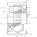
- the heat exchanger is with vertical axis and comprises a bundle of tubes identical to the one described for the solution of fig. 1 . Also the other elements of the exchanger, plenum 109, 110, tubes 102, 103, 104, 105, annular passage G formed between the outer surface 102' of the inner tube 102, and the inner surface 103' of the outer tube 103, tube plates 112, 113 are nearly identical except for their vertical arrangement.
- connection tubes 4, 104, 5, 105 respectively between feeding manifold 6 and annular passage and between annular passage and outlet manifold 7 is studied avoiding sub-manifolds, i.e. in order to have small flexible and independent ducts.
- each duct is free to expand and each duct can be closed mechanically or by welding so that a possible leakage is isolated.
- the plenum 9, 10, 109, 110 are provided with a device 17, 117, for example an Archimedean screw for a rapid ash or other solid materials elimination provided in the contaminated gases.
- both the upper and lower tube plates 112, 113 are realized with a "stepped" shape or more generally they are inclined with respect to the axis of the exchanger, so that the plenum 109, 110 are provided with passage sections proportional to the fluid flow rate so that the speed of the gas inside the plenum 109, 110 and as a consequence inside the tubes 112 is almost constant.
- FIG. 3 it is shown a detail, in transverse section, of a lined tube 1 from the gas inlet side.
- the inner tube 2 having an outer diameter between 40 and 100 mm, limited by the outer tube 3 coaxial to the same and welded to both the ends of the tube 2.
- the interspace between the two tubes makes up the annular passage G.
- a wire 11 or other helically wound structural around the tube 2 which has the function to maintain the outer tube 3 at constant distance and as a consequence to maintain a section of the annular passage G constant as well as to increase the fluid speed with equal flow rate.
- said annular passage G has a radial dimension preferably between 2 and 4 mm.
- the dimensioning of the wire 11 depends on the working fluid used considering the possible evaporation of the fluid during the crossing of the annular passage G and the consequent volumetric flow rate variation.
- independent tubes 5 are introduced which are welded to the bundle of tubes 1 and which make the water or cooling fluid go out from the annular passage G towards the manifold.
- the outer tube 3 is provided with a corrugated profile 15 able to absorb the thermal expansions of the inner tube 2. It is to be noted that the same corrugated profile is not apt for the inner tube 2 since its cleaning is not eased. Therefore, the adopted reason for the inner tube 2 is that of the end free to be deformed.
- the outer wall can be realized in two sections, connected to a welded expansion element.
- FIG 4 it is shown a detail of a lined tube 1 from the gas outlet side.
- independent connection tubes 4 are introduced by welding to the bundle of tubes.
- the tube plate 13 guides the tube 1 at its free end.
- seal 14 since there are no welded junctions between the tube and the tube plate, it is needed to use a seal 14.
- Said seal 14 can be a suitable gasket, for example a mechanical seal, realized by a metal disk and an elastic push element, or a seal in elastomeric or metal-elastomeric mixed material (lip seal ring).
- the volume limiting the outer wall of the tubes is obviously in connection with the outer environment (air at atmospheric pressure). If the free end of the tube 1 is not realized as a seal, an air flow is induced by this volume to the outlet plenum 10, if, as usually, is at a pressure slightly lower than the atmospheric one.
- Said vertical tubes 102 can be cleaned by any known device, preferably a helical insert which can be guided alternately or rotatingly inside the tube 102 through plugs 116 positioned in the upper portion of the plenum 109.
- an automatic brush tubular or shotblasting cleaner can be used to maintain clean the inner surface of the tube 102.
- the whole bundle of tubes 1, in case of feeding break of the cooling fluid from the manifold 6, as in the case in which the flow remains but the fluid comes back to the exchanger without a suitable cooling, can be cooled by an air flow coming from the outer environment, by means of suitable blowers 18.
- the system should be enclosed in a container, with dimensions and stacking characteristics according to the standards, so that the transport costs are reduced.
- the fluid receiving and transporting heat by crossing the interspace G between the outer tube and the inner one can be any heat bringing fluid (diathermal oil, pressured water, molten salt, liquid metal as for example molten Pb, as well as the working fluid of a cycle, for example a Rankine cycle with organic working fluid.
- fluid diathermal oil, pressured water, molten salt, liquid metal as for example molten Pb, as well as the working fluid of a cycle, for example a Rankine cycle with organic working fluid.
Landscapes
- Engineering & Computer Science (AREA)
- Physics & Mathematics (AREA)
- Thermal Sciences (AREA)
- Mechanical Engineering (AREA)
- General Engineering & Computer Science (AREA)
- Geometry (AREA)
- Heat-Exchange Devices With Radiators And Conduit Assemblies (AREA)
Claims (10)
- Wärmetauscher (100, 200) zum Kühlen von verunreinigten Flüssigkeiten Kühlung, die mit einer variablen thermischen Belastung ausgesetzt sind, mit Hilfe eines Wärmeaustausches mit einem aufnehmenden Flüssigkeits-und/oder dampfförmigen Fluid, wobei der genannte Wärmetauscher einen Bündel von Rohren umfasst, der aus einer Mehrzahl von unabhängigen Rohren (1), von zwei Plenum (9, 10, 109, 110), und Platten (12, 13, 112, 113) gebildet wird, wobei- die genannten unabhängigen Rohre (1) ein Innenrohr (2, 102), in dem das verunreinigte Gas fließt, und ein Außenrohr (3, 103) umfassen, wobei das genannte Innenrohr (2, 102) und Außenrohr (3, 103) koaxial sind und wobei zwischen der äußeren Oberfläche (2', 102) des Innenrohrs (2, 102) und der inneren Fläche (3', 103') des Außenrohres (3, 103) ein ringförmiger Durchgang G definiert wird, in den das aufnehmendes Fluid fließt;- das genannte Innenrohr (2, 102) ist mit der Platte (2, 112) in einem Gaseinlassbereich verschweißt, wobei der Wärmetauscher dadurch gekennzeichnet ist, dass ein Gasauslassbereich in einem entsprechenden Loch (13, 113) der Platte derart geführt ist, dass die Ausdehnung des Innenrohres (2, 102) in einer axialen Richtung nicht gebunden ist.
- Wärmetauscher nach Anspruch 1, wobei der genannte ringförmiger Durchgang G hydraulisch mit einem Einlasskrümmer (6) des aufnehmenden Fluides verbunden ist, durch unabhängige Verbindungsrohre (4, 104) die an beiden Ende jeweils mit dem Krümmer (6) und dem entsprechenden Außenrohr (3, 103) verbunden sind, und wobei der genannte ringförmige Durchgang G mit einem Auslasskrümmer (7) der aufnehmenden Fluides verbunden ist, durch unabhängige Rohre (5, 105), die an beiden Enden sowohl am Krümmer (7) als am entsprechenden Außenrohr (3, 103) verschweißt sind.
- Wärmetauscher nach den Ansprüchen 1 oder 2, wobei das genannte äußere Rohr (3, 103) abnehmbar an beiden Enden des inneren Rohrs (2, 102) verbunden ist.
- Wärmetauscher nach einem der Ansprüche 1 bis 3, wobei das genannte Innenrohr (2, 102) einen Außendurchmesser zwischen 40 und 100 mm aufweist.
- Wärmetauscher nach einem der Ansprüche 1 bis 4, wobei im Inneren des genannten ringförmigen Durchgangs G ein Gewinde (11) angeordnet ist, das spiralförmig um das Innenrohr (2, 102) gewickelt wird und die Funktion der Aufrechterhaltung des äußeren Rohres (3, 103) in einem konstanten Abstand aufweist, und dann einen konstanten Querschnitt des ringförmigen Durchgangs (G) zuhält.
- Wärmetauscher nach einem der Ansprüche 1 bis 5, wobei der genannte ringförmige Durchgang eine radiale Abmessung G zwischen 2 und 4 mm aufweist.
- Wärmetauscher nach einem der Ansprüche 1 bis 6, wobei der endliche Teil des Rohres (1) ein Außenrohr (3, 103) umfasst, das ein gewelltes Profil (15) aufweist, das in der Lage ist, die thermische Ausdehnung des Innenrohrs (2, 112) zu absorbieren.
- Wärmetauscher nach einem der Ansprüche 1 bis 7, wobei die genannten Platten (112, 113) in Stufen angeordnet sind oder entlang der Achse des Wärmetauschers derart geneigt sind, dass das Plenum (109, 110) Querschnitte aufweist, die derart proportional zur Strömungsgeschwindigkeit des Fluidstroms sind, dass sie eine konstante Geschwindigkeit des Gases innerhalb des Plenums (109, 110) und folglich in den Rohren (112) erhalten.
- Wärmetauscher nach einem der vorhergehenden Ansprüchen, wobei die Verbindungsrohre (4) konvergent in einem oberen Teil des ringförmigen Durchgangs (G) sind und Verbindungsrohre (5) sich von einem unteren Teil des ringförmigen Durchgangs (G) erstrecken.
- Wärmetauscher nach einem der vorhergehenden Ansprüche, wobei die genannten Verbindungsrohre (4, 104.5, 105) unabhängig voneinander sind, wobei sich jedes der genannten Verbindungsrohre erweitert und durch eine permanente mechanische Ausdehnung oder mittels einer Schweißung okkludiert wird.
Applications Claiming Priority (2)
| Application Number | Priority Date | Filing Date | Title |
|---|---|---|---|
| ITBS20140094 | 2014-05-14 | ||
| PCT/IB2015/052601 WO2015173673A1 (en) | 2014-05-14 | 2015-04-09 | Heat exchanger for contaminated fluids and subjected to strong variable heat load |
Publications (2)
| Publication Number | Publication Date |
|---|---|
| EP3143354A1 EP3143354A1 (de) | 2017-03-22 |
| EP3143354B1 true EP3143354B1 (de) | 2017-09-13 |
Family
ID=51541140
Family Applications (1)
| Application Number | Title | Priority Date | Filing Date |
|---|---|---|---|
| EP15725116.6A Active EP3143354B1 (de) | 2014-05-14 | 2015-04-09 | Wärmetauscher für verunreinigte fluide, die einer stark variierenden wärmebelastung ausgesetzt sind |
Country Status (3)
| Country | Link |
|---|---|
| US (1) | US10605535B2 (de) |
| EP (1) | EP3143354B1 (de) |
| WO (1) | WO2015173673A1 (de) |
Family Cites Families (11)
| Publication number | Priority date | Publication date | Assignee | Title |
|---|---|---|---|---|
| US3144080A (en) * | 1961-03-02 | 1964-08-11 | Schmidt Sche Heissdampf | Heat exchanger for the cooling of freshly cracked gases or the like |
| DE1211668B (de) * | 1961-03-02 | 1966-03-03 | Schmidt Sche Heissdampf | Roehrenwaermeaustauscher zum Kuehlen frischer Spaltgase od. dgl. |
| FR87777E (fr) * | 1964-04-16 | 1966-02-11 | Schmidt Sche Heissdampf | échangeur de température, notamment pour le refroidissement de gaz sortant de craquage ou autres |
| US3494414A (en) * | 1968-03-21 | 1970-02-10 | American Standard Inc | Heat exchanger having improved seal for the floating tube sheet |
| JPS4941378B1 (de) * | 1970-07-21 | 1974-11-08 | ||
| DE2509897A1 (de) * | 1975-03-07 | 1976-09-16 | Heinz Hoelter | Waermetauscher und grobstaub-abscheider fuer staubbeladenes heissgas |
| US4090554A (en) * | 1976-11-17 | 1978-05-23 | The Babcock & Wilcox Company | Heat exchanger |
| JP4033402B2 (ja) * | 2004-04-27 | 2008-01-16 | 本田技研工業株式会社 | 熱交換器 |
| US20090008074A1 (en) * | 2007-07-02 | 2009-01-08 | Vamvakitis Dimitri L | Tubular heat exchanger |
| US9528777B2 (en) * | 2012-06-29 | 2016-12-27 | Dana Canada Corporation | Heat exchangers with floating headers |
| US9688927B2 (en) * | 2012-09-13 | 2017-06-27 | General Electric Company | System for accommodating differential thermal expansion in syngas cooler |
-
2015
- 2015-04-09 WO PCT/IB2015/052601 patent/WO2015173673A1/en not_active Ceased
- 2015-04-09 EP EP15725116.6A patent/EP3143354B1/de active Active
- 2015-04-09 US US15/302,935 patent/US10605535B2/en not_active Expired - Fee Related
Non-Patent Citations (1)
| Title |
|---|
| None * |
Also Published As
| Publication number | Publication date |
|---|---|
| US10605535B2 (en) | 2020-03-31 |
| EP3143354A1 (de) | 2017-03-22 |
| US20170030653A1 (en) | 2017-02-02 |
| WO2015173673A1 (en) | 2015-11-19 |
Similar Documents
| Publication | Publication Date | Title |
|---|---|---|
| CN105180687B (zh) | 一种双壳程折流杆管壳式换热器 | |
| US9885523B2 (en) | Liquid to liquid multi-pass countercurrent heat exchanger | |
| EP2469215B1 (de) | Röhrenwärmetauscher | |
| EP3101340B1 (de) | Wärmetauscher | |
| CN201517899U (zh) | 一种管壳式换热器 | |
| CN205102639U (zh) | 一种管壳式换热器 | |
| CN206695650U (zh) | 带有前端管箱的填料函套管式换热器 | |
| RU2489663C1 (ru) | Теплообменник | |
| CN110686532A (zh) | 一种便携式平面弹性阵列涡管换热装置 | |
| US20130269907A1 (en) | Steam-to-gas heat exchanger | |
| CN206974236U (zh) | 壳程多股流绕管式换热器 | |
| CN209857696U (zh) | 一种缠绕管式毛细管换热器 | |
| US3628508A (en) | Waste-heat boilers and like gas/liquid heat transfer systems | |
| EP3143354B1 (de) | Wärmetauscher für verunreinigte fluide, die einer stark variierenden wärmebelastung ausgesetzt sind | |
| CN108387117B (zh) | 一种内外双对流管式换热器 | |
| CN207501760U (zh) | 双层螺旋式换热器 | |
| CN205373463U (zh) | 防止交叉污染的双管板式换热器 | |
| CN215864775U (zh) | 发夹式高效换热器 | |
| CN208398684U (zh) | 一种防泄漏双管板换热器 | |
| CN104976905A (zh) | 真空冷凝冷却器 | |
| CN210089460U (zh) | 一种石油化工用换热器 | |
| KR20170005086A (ko) | 합성 가스를 냉각시키기 위한 열 교환 디바이스 및 그의 조립 방법 | |
| CN103808175A (zh) | 适用于清洁介质蒸发的高压卧式换热器 | |
| CN208567597U (zh) | 一种内外双对流管式换热器 | |
| CN114152119B (zh) | 波浪形石墨翅片换热器 |
Legal Events
| Date | Code | Title | Description |
|---|---|---|---|
| PUAI | Public reference made under article 153(3) epc to a published international application that has entered the european phase |
Free format text: ORIGINAL CODE: 0009012 |
|
| 17P | Request for examination filed |
Effective date: 20161125 |
|
| AK | Designated contracting states |
Kind code of ref document: A1 Designated state(s): AL AT BE BG CH CY CZ DE DK EE ES FI FR GB GR HR HU IE IS IT LI LT LU LV MC MK MT NL NO PL PT RO RS SE SI SK SM TR |
|
| AX | Request for extension of the european patent |
Extension state: BA ME |
|
| GRAP | Despatch of communication of intention to grant a patent |
Free format text: ORIGINAL CODE: EPIDOSNIGR1 |
|
| INTG | Intention to grant announced |
Effective date: 20170404 |
|
| GRAS | Grant fee paid |
Free format text: ORIGINAL CODE: EPIDOSNIGR3 |
|
| GRAA | (expected) grant |
Free format text: ORIGINAL CODE: 0009210 |
|
| DAV | Request for validation of the european patent (deleted) | ||
| DAX | Request for extension of the european patent (deleted) | ||
| AK | Designated contracting states |
Kind code of ref document: B1 Designated state(s): AL AT BE BG CH CY CZ DE DK EE ES FI FR GB GR HR HU IE IS IT LI LT LU LV MC MK MT NL NO PL PT RO RS SE SI SK SM TR |
|
| REG | Reference to a national code |
Ref country code: GB Ref legal event code: FG4D |
|
| REG | Reference to a national code |
Ref country code: CH Ref legal event code: EP |
|
| REG | Reference to a national code |
Ref country code: IE Ref legal event code: FG4D |
|
| REG | Reference to a national code |
Ref country code: AT Ref legal event code: REF Ref document number: 928578 Country of ref document: AT Kind code of ref document: T Effective date: 20171015 |
|
| REG | Reference to a national code |
Ref country code: DE Ref legal event code: R096 Ref document number: 602015004792 Country of ref document: DE |
|
| REG | Reference to a national code |
Ref country code: NL Ref legal event code: MP Effective date: 20170913 |
|
| REG | Reference to a national code |
Ref country code: LT Ref legal event code: MG4D |
|
| PG25 | Lapsed in a contracting state [announced via postgrant information from national office to epo] |
Ref country code: LT Free format text: LAPSE BECAUSE OF FAILURE TO SUBMIT A TRANSLATION OF THE DESCRIPTION OR TO PAY THE FEE WITHIN THE PRESCRIBED TIME-LIMIT Effective date: 20170913 Ref country code: NO Free format text: LAPSE BECAUSE OF FAILURE TO SUBMIT A TRANSLATION OF THE DESCRIPTION OR TO PAY THE FEE WITHIN THE PRESCRIBED TIME-LIMIT Effective date: 20171213 Ref country code: FI Free format text: LAPSE BECAUSE OF FAILURE TO SUBMIT A TRANSLATION OF THE DESCRIPTION OR TO PAY THE FEE WITHIN THE PRESCRIBED TIME-LIMIT Effective date: 20170913 Ref country code: HR Free format text: LAPSE BECAUSE OF FAILURE TO SUBMIT A TRANSLATION OF THE DESCRIPTION OR TO PAY THE FEE WITHIN THE PRESCRIBED TIME-LIMIT Effective date: 20170913 Ref country code: SE Free format text: LAPSE BECAUSE OF FAILURE TO SUBMIT A TRANSLATION OF THE DESCRIPTION OR TO PAY THE FEE WITHIN THE PRESCRIBED TIME-LIMIT Effective date: 20170913 |
|
| REG | Reference to a national code |
Ref country code: AT Ref legal event code: MK05 Ref document number: 928578 Country of ref document: AT Kind code of ref document: T Effective date: 20170913 |
|
| PG25 | Lapsed in a contracting state [announced via postgrant information from national office to epo] |
Ref country code: LV Free format text: LAPSE BECAUSE OF FAILURE TO SUBMIT A TRANSLATION OF THE DESCRIPTION OR TO PAY THE FEE WITHIN THE PRESCRIBED TIME-LIMIT Effective date: 20170913 Ref country code: GR Free format text: LAPSE BECAUSE OF FAILURE TO SUBMIT A TRANSLATION OF THE DESCRIPTION OR TO PAY THE FEE WITHIN THE PRESCRIBED TIME-LIMIT Effective date: 20171214 Ref country code: RS Free format text: LAPSE BECAUSE OF FAILURE TO SUBMIT A TRANSLATION OF THE DESCRIPTION OR TO PAY THE FEE WITHIN THE PRESCRIBED TIME-LIMIT Effective date: 20170913 Ref country code: ES Free format text: LAPSE BECAUSE OF FAILURE TO SUBMIT A TRANSLATION OF THE DESCRIPTION OR TO PAY THE FEE WITHIN THE PRESCRIBED TIME-LIMIT Effective date: 20170913 Ref country code: BG Free format text: LAPSE BECAUSE OF FAILURE TO SUBMIT A TRANSLATION OF THE DESCRIPTION OR TO PAY THE FEE WITHIN THE PRESCRIBED TIME-LIMIT Effective date: 20171213 |
|
| REG | Reference to a national code |
Ref country code: FR Ref legal event code: PLFP Year of fee payment: 4 |
|
| PG25 | Lapsed in a contracting state [announced via postgrant information from national office to epo] |
Ref country code: NL Free format text: LAPSE BECAUSE OF FAILURE TO SUBMIT A TRANSLATION OF THE DESCRIPTION OR TO PAY THE FEE WITHIN THE PRESCRIBED TIME-LIMIT Effective date: 20170913 |
|
| PG25 | Lapsed in a contracting state [announced via postgrant information from national office to epo] |
Ref country code: PL Free format text: LAPSE BECAUSE OF FAILURE TO SUBMIT A TRANSLATION OF THE DESCRIPTION OR TO PAY THE FEE WITHIN THE PRESCRIBED TIME-LIMIT Effective date: 20170913 Ref country code: CZ Free format text: LAPSE BECAUSE OF FAILURE TO SUBMIT A TRANSLATION OF THE DESCRIPTION OR TO PAY THE FEE WITHIN THE PRESCRIBED TIME-LIMIT Effective date: 20170913 |
|
| PG25 | Lapsed in a contracting state [announced via postgrant information from national office to epo] |
Ref country code: EE Free format text: LAPSE BECAUSE OF FAILURE TO SUBMIT A TRANSLATION OF THE DESCRIPTION OR TO PAY THE FEE WITHIN THE PRESCRIBED TIME-LIMIT Effective date: 20170913 Ref country code: IS Free format text: LAPSE BECAUSE OF FAILURE TO SUBMIT A TRANSLATION OF THE DESCRIPTION OR TO PAY THE FEE WITHIN THE PRESCRIBED TIME-LIMIT Effective date: 20180113 Ref country code: SM Free format text: LAPSE BECAUSE OF FAILURE TO SUBMIT A TRANSLATION OF THE DESCRIPTION OR TO PAY THE FEE WITHIN THE PRESCRIBED TIME-LIMIT Effective date: 20170913 Ref country code: SK Free format text: LAPSE BECAUSE OF FAILURE TO SUBMIT A TRANSLATION OF THE DESCRIPTION OR TO PAY THE FEE WITHIN THE PRESCRIBED TIME-LIMIT Effective date: 20170913 Ref country code: AT Free format text: LAPSE BECAUSE OF FAILURE TO SUBMIT A TRANSLATION OF THE DESCRIPTION OR TO PAY THE FEE WITHIN THE PRESCRIBED TIME-LIMIT Effective date: 20170913 |
|
| REG | Reference to a national code |
Ref country code: DE Ref legal event code: R097 Ref document number: 602015004792 Country of ref document: DE |
|
| PLBE | No opposition filed within time limit |
Free format text: ORIGINAL CODE: 0009261 |
|
| STAA | Information on the status of an ep patent application or granted ep patent |
Free format text: STATUS: NO OPPOSITION FILED WITHIN TIME LIMIT |
|
| PG25 | Lapsed in a contracting state [announced via postgrant information from national office to epo] |
Ref country code: DK Free format text: LAPSE BECAUSE OF FAILURE TO SUBMIT A TRANSLATION OF THE DESCRIPTION OR TO PAY THE FEE WITHIN THE PRESCRIBED TIME-LIMIT Effective date: 20170913 |
|
| 26N | No opposition filed |
Effective date: 20180614 |
|
| PG25 | Lapsed in a contracting state [announced via postgrant information from national office to epo] |
Ref country code: MC Free format text: LAPSE BECAUSE OF FAILURE TO SUBMIT A TRANSLATION OF THE DESCRIPTION OR TO PAY THE FEE WITHIN THE PRESCRIBED TIME-LIMIT Effective date: 20170913 |
|
| REG | Reference to a national code |
Ref country code: CH Ref legal event code: PL |
|
| REG | Reference to a national code |
Ref country code: BE Ref legal event code: MM Effective date: 20180430 |
|
| REG | Reference to a national code |
Ref country code: IE Ref legal event code: MM4A |
|
| PG25 | Lapsed in a contracting state [announced via postgrant information from national office to epo] |
Ref country code: LU Free format text: LAPSE BECAUSE OF NON-PAYMENT OF DUE FEES Effective date: 20180409 |
|
| PG25 | Lapsed in a contracting state [announced via postgrant information from national office to epo] |
Ref country code: LI Free format text: LAPSE BECAUSE OF NON-PAYMENT OF DUE FEES Effective date: 20180430 Ref country code: CH Free format text: LAPSE BECAUSE OF NON-PAYMENT OF DUE FEES Effective date: 20180430 Ref country code: BE Free format text: LAPSE BECAUSE OF NON-PAYMENT OF DUE FEES Effective date: 20180430 |
|
| PG25 | Lapsed in a contracting state [announced via postgrant information from national office to epo] |
Ref country code: IE Free format text: LAPSE BECAUSE OF NON-PAYMENT OF DUE FEES Effective date: 20180409 |
|
| GBPC | Gb: european patent ceased through non-payment of renewal fee |
Effective date: 20190409 |
|
| PG25 | Lapsed in a contracting state [announced via postgrant information from national office to epo] |
Ref country code: GB Free format text: LAPSE BECAUSE OF NON-PAYMENT OF DUE FEES Effective date: 20190409 Ref country code: MT Free format text: LAPSE BECAUSE OF NON-PAYMENT OF DUE FEES Effective date: 20180409 |
|
| PG25 | Lapsed in a contracting state [announced via postgrant information from national office to epo] |
Ref country code: PT Free format text: LAPSE BECAUSE OF FAILURE TO SUBMIT A TRANSLATION OF THE DESCRIPTION OR TO PAY THE FEE WITHIN THE PRESCRIBED TIME-LIMIT Effective date: 20170913 |
|
| PG25 | Lapsed in a contracting state [announced via postgrant information from national office to epo] |
Ref country code: MK Free format text: LAPSE BECAUSE OF NON-PAYMENT OF DUE FEES Effective date: 20170913 Ref country code: HU Free format text: LAPSE BECAUSE OF FAILURE TO SUBMIT A TRANSLATION OF THE DESCRIPTION OR TO PAY THE FEE WITHIN THE PRESCRIBED TIME-LIMIT; INVALID AB INITIO Effective date: 20150409 Ref country code: RO Free format text: LAPSE BECAUSE OF FAILURE TO SUBMIT A TRANSLATION OF THE DESCRIPTION OR TO PAY THE FEE WITHIN THE PRESCRIBED TIME-LIMIT Effective date: 20170913 Ref country code: CY Free format text: LAPSE BECAUSE OF FAILURE TO SUBMIT A TRANSLATION OF THE DESCRIPTION OR TO PAY THE FEE WITHIN THE PRESCRIBED TIME-LIMIT Effective date: 20170913 |
|
| PG25 | Lapsed in a contracting state [announced via postgrant information from national office to epo] |
Ref country code: AL Free format text: LAPSE BECAUSE OF FAILURE TO SUBMIT A TRANSLATION OF THE DESCRIPTION OR TO PAY THE FEE WITHIN THE PRESCRIBED TIME-LIMIT Effective date: 20170913 |
|
| PG25 | Lapsed in a contracting state [announced via postgrant information from national office to epo] |
Ref country code: SI Free format text: LAPSE BECAUSE OF NON-PAYMENT OF DUE FEES Effective date: 20180409 |
|
| PGFP | Annual fee paid to national office [announced via postgrant information from national office to epo] |
Ref country code: FR Payment date: 20210319 Year of fee payment: 7 |
|
| PGFP | Annual fee paid to national office [announced via postgrant information from national office to epo] |
Ref country code: TR Payment date: 20210405 Year of fee payment: 7 |
|
| PGFP | Annual fee paid to national office [announced via postgrant information from national office to epo] |
Ref country code: DE Payment date: 20220317 Year of fee payment: 8 |
|
| PG25 | Lapsed in a contracting state [announced via postgrant information from national office to epo] |
Ref country code: FR Free format text: LAPSE BECAUSE OF NON-PAYMENT OF DUE FEES Effective date: 20220430 |
|
| REG | Reference to a national code |
Ref country code: DE Ref legal event code: R119 Ref document number: 602015004792 Country of ref document: DE |
|
| PG25 | Lapsed in a contracting state [announced via postgrant information from national office to epo] |
Ref country code: DE Free format text: LAPSE BECAUSE OF NON-PAYMENT OF DUE FEES Effective date: 20231103 |
|
| PG25 | Lapsed in a contracting state [announced via postgrant information from national office to epo] |
Ref country code: TR Free format text: LAPSE BECAUSE OF NON-PAYMENT OF DUE FEES Effective date: 20220409 |
|
| PGFP | Annual fee paid to national office [announced via postgrant information from national office to epo] |
Ref country code: IT Payment date: 20260316 Year of fee payment: 12 |