EP3143373B1 - Infrarotdetektionsmodul und zugehörige infrarotbetrachtungsvorrichtung - Google Patents
Infrarotdetektionsmodul und zugehörige infrarotbetrachtungsvorrichtung Download PDFInfo
- Publication number
- EP3143373B1 EP3143373B1 EP15725543.1A EP15725543A EP3143373B1 EP 3143373 B1 EP3143373 B1 EP 3143373B1 EP 15725543 A EP15725543 A EP 15725543A EP 3143373 B1 EP3143373 B1 EP 3143373B1
- Authority
- EP
- European Patent Office
- Prior art keywords
- housing
- detector
- nut
- cooling machine
- module according
- Prior art date
- Legal status (The legal status is an assumption and is not a legal conclusion. Google has not performed a legal analysis and makes no representation as to the accuracy of the status listed.)
- Active
Links
Images

Classifications
-
- G—PHYSICS
- G01—MEASURING; TESTING
- G01J—MEASUREMENT OF INTENSITY, VELOCITY, SPECTRAL CONTENT, POLARISATION, PHASE OR PULSE CHARACTERISTICS OF INFRARED, VISIBLE OR ULTRAVIOLET LIGHT; COLORIMETRY; RADIATION PYROMETRY
- G01J5/00—Radiation pyrometry, e.g. infrared or optical thermometry
- G01J5/02—Constructional details
- G01J5/06—Arrangements for eliminating effects of disturbing radiation; Arrangements for compensating changes in sensitivity
- G01J5/061—Arrangements for eliminating effects of disturbing radiation; Arrangements for compensating changes in sensitivity by controlling the temperature of the apparatus or parts thereof, e.g. using cooling means or thermostats
-
- F—MECHANICAL ENGINEERING; LIGHTING; HEATING; WEAPONS; BLASTING
- F25—REFRIGERATION OR COOLING; COMBINED HEATING AND REFRIGERATION SYSTEMS; HEAT PUMP SYSTEMS; MANUFACTURE OR STORAGE OF ICE; LIQUEFACTION SOLIDIFICATION OF GASES
- F25D—REFRIGERATORS; COLD ROOMS; ICE-BOXES; COOLING OR FREEZING APPARATUS NOT OTHERWISE PROVIDED FOR
- F25D19/00—Arrangement or mounting of refrigeration units with respect to devices or objects to be refrigerated, e.g. infrared detectors
-
- G—PHYSICS
- G01—MEASURING; TESTING
- G01J—MEASUREMENT OF INTENSITY, VELOCITY, SPECTRAL CONTENT, POLARISATION, PHASE OR PULSE CHARACTERISTICS OF INFRARED, VISIBLE OR ULTRAVIOLET LIGHT; COLORIMETRY; RADIATION PYROMETRY
- G01J5/00—Radiation pyrometry, e.g. infrared or optical thermometry
- G01J5/02—Constructional details
- G01J5/04—Casings
- G01J5/041—Mountings in enclosures or in a particular environment
- G01J5/045—Sealings; Vacuum enclosures; Encapsulated packages; Wafer bonding structures; Getter arrangements
Definitions
- the invention relates to an infrared detection module, as well as to infrared vision equipment incorporating such a module.
- infrared vision equipment such as binoculars for example, which make it possible to visualize targets at night or through smoke.
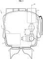
- the figure 1 schematically shows infrared vision binoculars 1.
- the binoculars 1 comprise a housing 2, an optical system 3, an infrared detection module 4, a processing module 5 and two display screens 6.
- the optical system 3 is arranged to transmit infrared radiation emitted by the target to the detection module 4.
- the detection module 4 converts the received infrared radiation into a detection signal which is transmitted to the processing module 5.
- the processing module 5 controls the display of an image on the display screens 6 to allow a user to view the target. To this end, the user positions his eyes in front of the display screens 6.
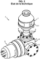
- the figure 2 schematically shows an infrared detection module 4.
- the infrared detection module 4 comprises a detection part 7, a cold production part 8 and a motorization part 9.
- the detection part 7 comprises an infrared detector, such as a matrix infrared detector or FPA (not shown in this figure).
- the cold production part 8 comprises a cold machine (not shown in this figure) ensuring the cooling of the infrared detector, to a temperature typically of the order of 80 degrees Kelvin.
- the detection part 7 comprises a detector casing 11 adapted to house the infrared detector
- the cold production part 8 comprises a cold machine casing 12 adapted to house the cold machine.
- the detector housing is generally screwed onto the cold machine housing by means of several fixing screws 9. Screwing must be carried out with high tightening torques (of the order of 2 Newton.meter) to seal the cold machine housing.
- the cold machine casing contains a cooling gas subjected to a high pressure (typically 20 bars) during operation of the cold machine.
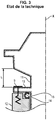
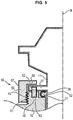
- the figure 3 schematically shows the principle of fixing the detector casing 11 on the cold machine casing 12.
- the detector casing 11 comprises a crown 13 suitable for bearing against the cold machine casing 12.
- the casing cold machine 12 has a shoulder 14 supporting a seal 15.
- the crown 13 of the detector casing 11 is screwed onto the cold machine casing 12, so as to bear against the cold machine casing 12 through the seal 15.
- the document WO2013 / 061327 discloses an infrared detector comprising a detector housing and a cold machine housing, the sensor housing being secured to the cold machine housing by means of fixing screws.
- JP2001183021 discloses the use of a nut for screwing two parts in a cold machine.
- the reduction in the dimensions of the heat exchanger leads to a reduction in the size of the infrared detection module in the direction of the optical axis X, and has the advantage of allowing the design of increasingly compact binoculars.
- the reduction in the size of the detection module also has the consequence of making it difficult to access the fixing screws 9, in particular using a tightening key.
- An object of the invention is to facilitate the assembly of the detector housing on the housing of the cold machine, in a detection module of reduced dimensions.
- the detection module can also be designed so that fixing of the housings is obtained by means of a single nut. In this way, the fixing requires only one screwing operation.
- the invention also relates to infrared vision equipment, comprising a detection module as defined above.
- the equipment can in particular be binoculars.
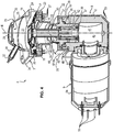
- the detection module 4 comprises a detection part 7, a cold production part 8 and a motorization part 9.
- the detection part 7 comprises an infrared matrix detector 16, a substrate 17 supporting the detector, a plug 18 in contact with the substrate and an intermediate cup 19 suitable for supporting a cold screen (not shown).
- the detection part 7 also comprises a detector housing defining a first cavity 21 (or detection chamber) in which the matrix infrared detector 16, the substrate 17, the plug 18 and the intermediate cup 19 are housed.
- the detector housing 11 comprises a cold finger 22, an electrical connection base 23, a cover support 24 and a cover 25.
- the infrared detector 16 is a CFPA (Cooled Focal Plane Array) detector consisting of a matrix of pixels sensitive to infrared radiation.
- the infrared detector 16 has a detection face of generally planar shape, suitable for receiving the infrared radiation coming from the target, and having an optical axis X perpendicular to the detection face and centered relative to the latter.
- the infrared detector 16 is electrically connected to contact pads 26 of the intermediate cup 19 by means of wiring by wires.
- the base 23 is formed of a dielectric material, such as glass, in which are embedded electrical pins 27 allowing collection of the electrical signals coming from the infrared detector 16 to the processing module 5.
- the cover 25 is mounted on the cover support 24.
- the cover 25 comprises a body 28, a sighting window 29, a tail 31 and a protective cap 32.
- the body 28 has a sighting opening 33 and a suction opening 34.
- the window 29 closes the sighting opening 33 and is formed of a material transparent to infrared radiation, for example in germanium.
- the queusot 31 has a first end connected to the suction opening 34 and a second end suitable for being connected to a suction device to create a partial vacuum (10 -6 bars) inside the first cavity 21
- the protective cap 32 closes the second end in order to maintain the vacuum created in the first cavity 21.
- the cold finger 22 has an elongated cylindrical part 35 extending inside the base 23 and a connecting part 36.
- the cylindrical part 35 is intended to contain the heat exchanger of the cold machine.
- the cylindrical part 35 comprises a thin cylindrical side wall surrounding the heat exchanger of the cold machine. The wall is closed at one end by the plug 18 which is in contact with the substrate 17 supporting the infrared detector 16, so as to ensure cooling of the detector 16.
- connection part 36 is adapted to contain the cylinder of the cold machine.
- the connection portion 36 comprises a thick cylindrical side wall, surrounding the cylinder of the cold machine, and a ring 37 extending around the cylindrical wall, in a radial plane with respect to the cylindrical wall.
- the crown 37 has a bearing surface 38 suitable for resting on the cold machine casing 12.
- the cold finger 22, the electrical connection base 23, the cover support 24 and the cover 25 are welded to each other, for example by laser welding, so as to make the first cavity 21 waterproof.
- the cold production part 8 comprises a cold machine 39 (partially shown) and a cold machine casing 12 suitable for housing the cold machine 39.
- the cold machine casing 12 defines a second cavity 41 containing the cold machine. cold 39, the second cavity 41 being filled with a cooling gas, such as helium (He).
- the cold machine 39 operates according to a cyclic Stirling process for cooling the cooling gas.
- the cold machine 39 comprises a cylinder 42, a piston 43 suitable for sliding in the cylinder and a heat exchanger 44.
- the heat exchanger 44 comprises a stack of cooling fins 45 and a regenerator tube 46 containing the stack.
- the cold machine casing 12 has an opening 47 suitable for receiving the connection portion 36 of the cold finger 22, and a collar 48 surrounding the opening 47.
- the collar 48 has a threaded external cylindrical surface 49.
- the collar 48 has a shoulder 51 in which is disposed a seal 52.
- the seal 52 is a seal having a C-shaped cross section.
- the cold machine casing 12 also has cooling fins 53 allowing cooling of the cooling gas by heat exchange with the ambient air.
- the motorization part 9 comprises an electric motor (not shown) and a motor casing 54 suitable for housing the electric motor.
- the electric motor is suitable for driving the piston 43 of the cold machine.
- Motor housing 54 has power pins 55 for connecting the electric motor to a power source.
- the detection module 4 also comprises a fixing device 56 for fixing the detector casing 11 on the cold machine casing 12.
- the fixing device 56 comprises a nut 57 surrounding the detector casing 11 and suitable for being screwed onto the machine. cold machine housing 12.
- the nut 57 is formed in a single piece of material.
- the nut 57 comprises a washer 58 adapted to come to bear against the crown 37 of the detector housing 11, and a ring 59 having a threaded internal surface 61 adapted to cooperate with the threaded external surface 49 of the cold machine housing 12 .
- the fixing device 56 comprises an indexing pin 62 fixed to the cold machine casing 12 and an indexing hole 63 formed in the detector casing 11.
- the indexing hole 63 is provided to receive the pin. indexing 62 so as to hold the detector housing 11 in position relative to the cold machine housing 12 while screwing the nut 57.
- the detection unit 4 being fixed in the box 2 of the binoculars 1 by the cold machine housing 12, the indexing pin 62 and the indexing hole 63 make it possible to obtain a correct angular orientation of the detector 16 in the binoculars 1.
- the nut 57 is first threaded on the cold finger 22, before the cold finger 22 is welded to the base 23. In this way, once the welding has been carried out, the nut 57 is inseparable from the detector housing 11.
- the assembly of the detection part 7 and the cold production part 8 is carried out as follows.
- connection portion 36 of the cold finger 22 is inserted into the cold machine housing 12 via the opening 47, until the sensor housing 11 comes to rest against the cold machine housing 12, more precisely, until the crown 37 comes to rest against the collar 48. Simultaneously, the heat exchanger 44 of the cold machine 39 is inserted into the cylindrical part 36 of the cold finger 22.
- the detection housing 11 is positioned relative to the cold machine housing 12 so that the indexing pin 62 penetrates the indexing hole 63, ensuring correct relative positioning between the two housings 11 and 12.
- the nut 57 is screwed onto the cold machine housing 12.
- the nut 57 is screwed around a screwing axis coincident with l 'optical axis X.
- the screwing of the nut 57 has the effect, on the one hand, of securing the casings 11 and 12 together, and on the other hand, of compressing the seal 52 between the two casings 11 and 12.
- the washer 58 of the nut 57 presses the seal 52 against the shoulder 51, by means of the crown 37. In this way, homogeneous compression of the seal 52 can be obtained.
- FIG. 6a and 6b schematically show an attachment of the housings 11 and 12 according to a second embodiment.
- This second embodiment is identical to the first embodiment, except that the sensor housing 11 does not include a crown 37. Instead, the sensor housing 11 includes a groove 64 formed in the cylindrical side wall of the sensor housing. 11, and an elastic ring 65 (or circlip) received in the groove 64. The elastic ring 65 can be inserted into the groove 64 using a circlip pliers.
- the elastic ring 65 has a bearing surface 66, on which the washer 58 of the nut 57 comes to bear to press the detector housing 11 against the cold machine housing 12.
- the detector housing 11 further comprises a shoulder 67 in which the seal 52 is disposed.
- the nut 57 further comprises an orifice 68 for inserting a lug of a lug wrench which can be used for screwing in the nut 57.
- the assembly of the detection part 7 and the cold production part 8 is carried out as follows.
- connection portion 36 of the cold finger 22 is inserted into the cold machine housing 12 through the opening 47, so that the gasket 52 is caught between the sensor housing 11 and the cold machine housing. 12 ( figure 6a ). More specifically, the seal 52 is caught between the shoulder 67 of the detector housing 11 and the collar 48 of the cold machine housing 12.
- the nut 57 is screwed onto the cold machine housing 12 ( figure 6b ), for example using a hook wrench.
- the nut 57 is screwed around a screwing axis coincident with the optical axis X.
- the screwing of the nut 57 has the effect, on the one hand, of securing the casings 11 and 12 together, and on the other hand, of compressing the seal 52 between the two casings 11 and 12.
- the washer 58 of the nut 57 presses the seal 52 against the collar 48, via the elastic ring 65.
- the fixing of the housings 11 and 12 together requires only a single screwing operation.
- an advantage of this second embodiment is that the nut 57 can be removed, that is to say that it can be separated from the housings 11 and 12. For this purpose, it suffices to remove the ring. elastic 65. This facilitates handling of the detection module (4) during its manufacture
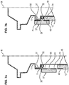
- the figures 7a and 7b schematically shows an attachment of the housings 11 and 12 according to a third embodiment.
- This third embodiment is identical to the first embodiment, except that the nut 57 does not include a washer 58.
- the nut 57 comprises an internal surface 61 having a first threaded portion 69 and a second threaded portion 70.
- the first threaded portion 69 has a first pitch and the second threaded portion 70 has a second pitch, reversed with respect to the first. not.
- the detector housing 11 has a threaded external surface 71 suitable for cooperating with the first threaded portion 69 of the nut 57. More precisely, the threaded external surface 71 is an external surface of the ring 37.
- the cold machine housing 12 has a threaded outer surface 49 suitable for cooperating with the second threaded portion 70 of the nut 57.
- nut 57 can be simultaneously screwed onto sensor housing 11 and cold machine housing 12 in a single screwing operation.
- the screwing of the nut on the casings 11 and 12 has the effect of compressing the seal 52 between the casings 11 and 12.
- the nut 57 can be removed by simply unscrewing the nut, which facilitates the handling of the detection module during its manufacture.
Landscapes
- Physics & Mathematics (AREA)
- Engineering & Computer Science (AREA)
- General Physics & Mathematics (AREA)
- Spectroscopy & Molecular Physics (AREA)
- Chemical & Material Sciences (AREA)
- Combustion & Propulsion (AREA)
- Mechanical Engineering (AREA)
- Thermal Sciences (AREA)
- General Engineering & Computer Science (AREA)
- Photometry And Measurement Of Optical Pulse Characteristics (AREA)
Claims (14)
- Infrarotdetektionsmodul (4), umfassend:- einen Detektionsteil (7), umfassend einen Infrarotdetektor (16) und ein Detektorgehäuse (11), das imstande ist, den Infrarotdetektor (16) unterzubringen,- einen Kälteproduktionsteil (8), umfassend eine Kältemaschine (39) zum Kühlen des Detektors (16) und ein Kältemaschinengehäuse (12), das imstande ist, die Kältemaschine (39) unterzubringen,- eine Befestigungsvorrichtung (56) zur Befestigung des Detektorgehäuses (11) auf dem Kältemaschinengehäuse (12), wobei die Befestigungsvorrichtung (56) eine Mutter (57) umfasst, die imstande ist, auf das Detektorgehäuse (11) und/oder auf das Kältemaschinengehäuse (12) derart geschraubt zu sein, dass die Gehäuse miteinander verbunden sind, und- einen Indexierstift (62), der auf einem der Gehäuse (11, 12) befestigt ist, und eine Indexieröffnung (63), die in dem anderen Gehäuse (11, 12) eingerichtet ist, wobei die Indexieröffnung (63) vorgesehen ist, den Indexierstift (62) derart aufzunehmen, dass die Gehäuse (11, 12) während des Schraubens der Mutter (57) zueinander in Position gehalten werden.
- Modul nach Anspruch 1, wobei das Detektorgehäuse (11) einen kalten Finger (22) umfasst, der einen länglichen zylindrischen Teil (35) aufweist, der bestimmt ist, einen Wärmetauscher (44) der Kältemaschine zu enthalten.
- Modul nach einem der Ansprüche 1 und 2, umfassend eine Dichtung (52), die zwischen dem Detektorgehäuse (11) und dem Kältemaschinengehäuse (12) angeordnet ist, und wobei die Verschraubung der Mutter (57) bewirkt, dass die Dichtung (52) zwischen dem Detektorgehäuse (11) und dem Kältemaschinengehäuse (12) komprimiert wird.
- Modul nach Anspruch 3, wobei die Dichtung (52) eine Dichtung mit einem C-förmigen Querschnitt ist.
- Modul nach einem der Ansprüche 1 bis 4, wobei die Mutter (57) eine Scheibe (58) umfasst, die imstande ist, sich auf einer Stützfläche des Detektorgehäuses (11) abzustützen, und eine innere gewindete Fläche (61), die imstande ist, mit einer äußeren gewindeten Fläche (49) des Kältemaschinengehäuses (12) zusammenzuwirken, wobei die Verschraubung der Mutter (57) auf dem Kältemaschinengehäuse (12) bewirkt, dass das Detektorgehäuse (11) mittels der Scheibe (58) gegen das Kältemaschinengehäuse (12) gespannt wird.
- Modul nach Anspruch 5, wobei das Detektorgehäuse (11) einen Kranz (37) umfasst, wobei die Stützfläche eine Fläche des Kranzes (37) ist.
- Modul nach Anspruch 5, wobei das Detektorgehäuse (11) eine Nut (64) und einen elastischen Ring (65) umfasst, der in der Nut (64) aufgenommen ist, wobei die Stützfläche eine Fläche (66) des elastischen Rings (65) ist.
- Modul nach einem der Ansprüche 1 bis 4, wobei die Mutter (57) eine innere Fläche (61) umfasst, die einen ersten gewindeten Abschnitt (69) aufweist, der imstande ist, mit einer äußeren gewindeten Fläche (71) des Detektorgehäuses (11) zusammenzuwirken, und einen zweiten gewindeten Abschnitt (70), der imstande ist, mit einer äußeren gewindeten Fläche (49) des Kältemaschinengehäuses (12) zusammenzuwirken.
- Modul nach Anspruch 8, wobei der erste gewindete Abschnitt (69) eine erste Steigung aufweist und der zweite gewindete Abschnitt (70) eine zweite Steigung umgekehrt in Bezug auf die erste Steigung aufweist.
- Modul nach einem der Ansprüche 1 bis 9, wobei die Mutter (57) das Detektorgehäuse (11) und/oder das Kältemaschinengehäuse (12) umgibt.
- Modul nach einem der Ansprüche 1 bis 10, wobei das Detektorgehäuse (11) umfasst:- einen ersten Teil (23), der einen Hohlraum (21) definiert, der den Infrarotdetektor (16) unterbringt, und- einen zweiten Teil (22), der imstande ist, in das Kältemaschinengehäuse (12) eingesetzt zu sein,wobei die Mutter (57) auf dem zweiten Teil (22) vor dem Verschweißen des ersten Teils (23) auf dem zweiten Teil (22) angebracht wurde, so dass, sobald die zwei Teile (22, 23) verschweißt sind, die Mutter (57) vom Detektorgehäuse (11) untrennbar ist.
- Modul nach einem der Ansprüche 1 bis 11, wobei der Detektor (4) eine optische Achse (X) aufweist und die Mutter (57) imstande ist, auf dem Detektorgehäuse (11) und/oder auf dem Kältemaschinengehäuse (12) um eine Schraubachse geschraubt zu sein, die mit der optischen Achse (X) zusammenfällt.
- Infrarotsichtausrüstung (1), umfassend ein Detektionsmodul (4) nach einem der Ansprüche 1 bis 12.
- Ausrüstung nach Anspruch 13, wobei die Ausrüstung (1) ein Infrarotsichtfernglas ist.
Applications Claiming Priority (2)
| Application Number | Priority Date | Filing Date | Title |
|---|---|---|---|
| FR1454333A FR3021153B1 (fr) | 2014-05-15 | 2014-05-15 | Module de detection infrarouge et equipement de vision infrarouge associe |
| PCT/EP2015/060783 WO2015173407A1 (fr) | 2014-05-15 | 2015-05-15 | Module de detection infrarouge et equipement de vision infrarouge associe |
Publications (2)
| Publication Number | Publication Date |
|---|---|
| EP3143373A1 EP3143373A1 (de) | 2017-03-22 |
| EP3143373B1 true EP3143373B1 (de) | 2020-11-11 |
Family
ID=51298793
Family Applications (1)
| Application Number | Title | Priority Date | Filing Date |
|---|---|---|---|
| EP15725543.1A Active EP3143373B1 (de) | 2014-05-15 | 2015-05-15 | Infrarotdetektionsmodul und zugehörige infrarotbetrachtungsvorrichtung |
Country Status (5)
| Country | Link |
|---|---|
| US (1) | US10393588B2 (de) |
| EP (1) | EP3143373B1 (de) |
| FR (1) | FR3021153B1 (de) |
| IL (1) | IL248927A0 (de) |
| WO (1) | WO2015173407A1 (de) |
Families Citing this family (2)
| Publication number | Priority date | Publication date | Assignee | Title |
|---|---|---|---|---|
| US11079281B2 (en) * | 2019-01-17 | 2021-08-03 | Uvia Group Llc | Cold stage actuation of optical elements including an optical light shield and a lenslet array connected to a cold finger |
| FR3141225B1 (fr) * | 2022-10-25 | 2025-03-14 | Safran Electronics & Defense | Element de liaison pour equipement de vision infrarouge |
Family Cites Families (9)
| Publication number | Priority date | Publication date | Assignee | Title |
|---|---|---|---|---|
| US3079504A (en) * | 1956-12-20 | 1963-02-26 | Frederick L Hutchens | Cooling device for infrared detector |
| US3064128A (en) * | 1958-10-17 | 1962-11-13 | Honeywell Regulator Co | Measuring apparatus |
| DE3502472C2 (de) * | 1985-01-25 | 1987-05-14 | Mannesmann AG, 4000 Düsseldorf | Verfahren zum Herstellen einer Ankerbaugruppe eines Matrixdruckkopfes |
| DE3742272C2 (de) * | 1987-12-12 | 1994-01-20 | Vallon Gmbh | Schnellkupplung für einen tragbaren Eisendetektor |
| JP2001183021A (ja) * | 1999-12-27 | 2001-07-06 | Sumitomo Heavy Ind Ltd | 冷凍機 |
| US20070017679A1 (en) * | 2005-06-30 | 2007-01-25 | Wolf John C | Downhole multi-action jetting tool |
| WO2008086455A2 (en) * | 2007-01-09 | 2008-07-17 | S/R Industries | Interchangeable gun barrel system and related methods |
| US8186876B2 (en) * | 2009-04-20 | 2012-05-29 | Welch Allyn, Inc. | Calibrated assembly for IR thermometer apparatus |
| IL215961A0 (en) * | 2011-10-26 | 2012-03-29 | Elbit Systems Ew And Sigint Elisra Ltd | A low profile cooled infra red sensor arranagement configured for aerial vehicles |
-
2014
- 2014-05-15 FR FR1454333A patent/FR3021153B1/fr not_active Expired - Fee Related
-
2015
- 2015-05-15 WO PCT/EP2015/060783 patent/WO2015173407A1/fr not_active Ceased
- 2015-05-15 US US15/311,161 patent/US10393588B2/en active Active
- 2015-05-15 EP EP15725543.1A patent/EP3143373B1/de active Active
-
2016
- 2016-11-13 IL IL248927A patent/IL248927A0/en active IP Right Grant
Also Published As
| Publication number | Publication date |
|---|---|
| FR3021153B1 (fr) | 2016-06-17 |
| FR3021153A1 (fr) | 2015-11-20 |
| US20170097265A1 (en) | 2017-04-06 |
| IL248927A0 (en) | 2017-01-31 |
| US10393588B2 (en) | 2019-08-27 |
| EP3143373A1 (de) | 2017-03-22 |
| WO2015173407A1 (fr) | 2015-11-19 |
Similar Documents
| Publication | Publication Date | Title |
|---|---|---|
| CA2784045C (fr) | Dispositif de controle thermique | |
| FR2913498A1 (fr) | Detecteur de gaz comprenant un boitier protege, en particulier, contre les explosions | |
| EP3143373B1 (de) | Infrarotdetektionsmodul und zugehörige infrarotbetrachtungsvorrichtung | |
| CN102997999A (zh) | 一种红外焦平面阵列探测器 | |
| JP2009290527A (ja) | カメラモジュール | |
| CN112268930B (zh) | 一种露点传感器 | |
| FR2777654A1 (fr) | Dispositif de mesure de la pression d'une atmosphere | |
| JP2000193892A (ja) | 内視鏡 | |
| MX2007015920A (es) | Alojamiento de encapsulado hermetico al gas para un dispositivo de transmision de energia. | |
| US20230140390A1 (en) | Structure and Method of Manufacturing for a Hermetic Housing Enclosure for a Thermal Shock Proof, Zero Thermal Gradient Imaging or Sensing Core | |
| EP1715314B1 (de) | Vorrichtung zur Detektion von Infrarotstrahlung, Lenksystem ausgestattet mit dieser Vorrichtung und selbstgesteuertes Geschoss ausgestattet mit diesem Lenksystem. | |
| CN113628935A (zh) | 气体绝缘金属封闭开关设备及其观察窗 | |
| WO2021237747A1 (zh) | 光学系统、精密装置及电子设备 | |
| CN119935431B (zh) | 一种定点式防爆型红外遥测气体检漏仪 | |
| EP2867716B1 (de) | Vorrichtung zur überwachung der externen umgebung einer plattform, insbesondere einer meeresplattform, periskop und plattform mit solch einer vorrichtung | |
| HK1263097B (zh) | 温度监控装置、具有该装置的外壳及相关安装方法 | |
| FR2991812A1 (fr) | Dispositif de detection refroidi avec table froide amelioree | |
| FR3145209A1 (fr) | Dispositif de détection de rayonnement électromagnétique | |
| EP0198549A2 (de) | Vorrichtung zur Begrenzung und Vergleichmässigung des Sichtfeldes von Mosaikanordnungen von Infrarotdetektoren | |
| JP6353752B2 (ja) | カメラ装置 | |
| JP2018022971A (ja) | 真空容器用の撮像装置 | |
| EP3686919A1 (de) | Blitzlampe mit gepulstem licht und optisches modul mit gepulstem licht, das diese lampe umfasst | |
| RU2007126290A (ru) | Многоканальный спектрометр | |
| WO2010109126A1 (fr) | Dispositif de confinement et d'analyse |
Legal Events
| Date | Code | Title | Description |
|---|---|---|---|
| STAA | Information on the status of an ep patent application or granted ep patent |
Free format text: STATUS: THE INTERNATIONAL PUBLICATION HAS BEEN MADE |
|
| PUAI | Public reference made under article 153(3) epc to a published international application that has entered the european phase |
Free format text: ORIGINAL CODE: 0009012 |
|
| STAA | Information on the status of an ep patent application or granted ep patent |
Free format text: STATUS: REQUEST FOR EXAMINATION WAS MADE |
|
| 17P | Request for examination filed |
Effective date: 20161213 |
|
| AK | Designated contracting states |
Kind code of ref document: A1 Designated state(s): AL AT BE BG CH CY CZ DE DK EE ES FI FR GB GR HR HU IE IS IT LI LT LU LV MC MK MT NL NO PL PT RO RS SE SI SK SM TR |
|
| AX | Request for extension of the european patent |
Extension state: BA ME |
|
| DAV | Request for validation of the european patent (deleted) | ||
| DAX | Request for extension of the european patent (deleted) | ||
| GRAP | Despatch of communication of intention to grant a patent |
Free format text: ORIGINAL CODE: EPIDOSNIGR1 |
|
| STAA | Information on the status of an ep patent application or granted ep patent |
Free format text: STATUS: GRANT OF PATENT IS INTENDED |
|
| INTG | Intention to grant announced |
Effective date: 20200817 |
|
| RIN1 | Information on inventor provided before grant (corrected) |
Inventor name: DUVAL, NICOLAS Inventor name: RASSINOUX, PHILIPPE Inventor name: BIDAUD, MICHEL Inventor name: LEGOUBIN, PHILIPPE Inventor name: COTTEREAU, BERTRAND |
|
| GRAS | Grant fee paid |
Free format text: ORIGINAL CODE: EPIDOSNIGR3 |
|
| GRAA | (expected) grant |
Free format text: ORIGINAL CODE: 0009210 |
|
| STAA | Information on the status of an ep patent application or granted ep patent |
Free format text: STATUS: THE PATENT HAS BEEN GRANTED |
|
| AK | Designated contracting states |
Kind code of ref document: B1 Designated state(s): AL AT BE BG CH CY CZ DE DK EE ES FI FR GB GR HR HU IE IS IT LI LT LU LV MC MK MT NL NO PL PT RO RS SE SI SK SM TR |
|
| REG | Reference to a national code |
Ref country code: GB Ref legal event code: FG4D Free format text: NOT ENGLISH |
|
| REG | Reference to a national code |
Ref country code: CH Ref legal event code: EP |
|
| REG | Reference to a national code |
Ref country code: AT Ref legal event code: REF Ref document number: 1333934 Country of ref document: AT Kind code of ref document: T Effective date: 20201115 |
|
| REG | Reference to a national code |
Ref country code: DE Ref legal event code: R096 Ref document number: 602015061843 Country of ref document: DE |
|
| REG | Reference to a national code |
Ref country code: IE Ref legal event code: FG4D Free format text: LANGUAGE OF EP DOCUMENT: FRENCH |
|
| REG | Reference to a national code |
Ref country code: NL Ref legal event code: FP |
|
| RAP4 | Party data changed (patent owner data changed or rights of a patent transferred) |
Owner name: SAFRAN ELECTRONICS & DEFENSE |
|
| REG | Reference to a national code |
Ref country code: AT Ref legal event code: MK05 Ref document number: 1333934 Country of ref document: AT Kind code of ref document: T Effective date: 20201111 |
|
| PG25 | Lapsed in a contracting state [announced via postgrant information from national office to epo] |
Ref country code: FI Free format text: LAPSE BECAUSE OF FAILURE TO SUBMIT A TRANSLATION OF THE DESCRIPTION OR TO PAY THE FEE WITHIN THE PRESCRIBED TIME-LIMIT Effective date: 20201111 Ref country code: RS Free format text: LAPSE BECAUSE OF FAILURE TO SUBMIT A TRANSLATION OF THE DESCRIPTION OR TO PAY THE FEE WITHIN THE PRESCRIBED TIME-LIMIT Effective date: 20201111 Ref country code: NO Free format text: LAPSE BECAUSE OF FAILURE TO SUBMIT A TRANSLATION OF THE DESCRIPTION OR TO PAY THE FEE WITHIN THE PRESCRIBED TIME-LIMIT Effective date: 20210211 Ref country code: PT Free format text: LAPSE BECAUSE OF FAILURE TO SUBMIT A TRANSLATION OF THE DESCRIPTION OR TO PAY THE FEE WITHIN THE PRESCRIBED TIME-LIMIT Effective date: 20210311 Ref country code: GR Free format text: LAPSE BECAUSE OF FAILURE TO SUBMIT A TRANSLATION OF THE DESCRIPTION OR TO PAY THE FEE WITHIN THE PRESCRIBED TIME-LIMIT Effective date: 20210212 |
|
| PG25 | Lapsed in a contracting state [announced via postgrant information from national office to epo] |
Ref country code: LV Free format text: LAPSE BECAUSE OF FAILURE TO SUBMIT A TRANSLATION OF THE DESCRIPTION OR TO PAY THE FEE WITHIN THE PRESCRIBED TIME-LIMIT Effective date: 20201111 Ref country code: PL Free format text: LAPSE BECAUSE OF FAILURE TO SUBMIT A TRANSLATION OF THE DESCRIPTION OR TO PAY THE FEE WITHIN THE PRESCRIBED TIME-LIMIT Effective date: 20201111 Ref country code: IS Free format text: LAPSE BECAUSE OF FAILURE TO SUBMIT A TRANSLATION OF THE DESCRIPTION OR TO PAY THE FEE WITHIN THE PRESCRIBED TIME-LIMIT Effective date: 20210311 Ref country code: SE Free format text: LAPSE BECAUSE OF FAILURE TO SUBMIT A TRANSLATION OF THE DESCRIPTION OR TO PAY THE FEE WITHIN THE PRESCRIBED TIME-LIMIT Effective date: 20201111 Ref country code: BG Free format text: LAPSE BECAUSE OF FAILURE TO SUBMIT A TRANSLATION OF THE DESCRIPTION OR TO PAY THE FEE WITHIN THE PRESCRIBED TIME-LIMIT Effective date: 20210211 Ref country code: AT Free format text: LAPSE BECAUSE OF FAILURE TO SUBMIT A TRANSLATION OF THE DESCRIPTION OR TO PAY THE FEE WITHIN THE PRESCRIBED TIME-LIMIT Effective date: 20201111 |
|
| REG | Reference to a national code |
Ref country code: LT Ref legal event code: MG9D |
|
| PG25 | Lapsed in a contracting state [announced via postgrant information from national office to epo] |
Ref country code: HR Free format text: LAPSE BECAUSE OF FAILURE TO SUBMIT A TRANSLATION OF THE DESCRIPTION OR TO PAY THE FEE WITHIN THE PRESCRIBED TIME-LIMIT Effective date: 20201111 |
|
| PG25 | Lapsed in a contracting state [announced via postgrant information from national office to epo] |
Ref country code: LT Free format text: LAPSE BECAUSE OF FAILURE TO SUBMIT A TRANSLATION OF THE DESCRIPTION OR TO PAY THE FEE WITHIN THE PRESCRIBED TIME-LIMIT Effective date: 20201111 Ref country code: SK Free format text: LAPSE BECAUSE OF FAILURE TO SUBMIT A TRANSLATION OF THE DESCRIPTION OR TO PAY THE FEE WITHIN THE PRESCRIBED TIME-LIMIT Effective date: 20201111 Ref country code: RO Free format text: LAPSE BECAUSE OF FAILURE TO SUBMIT A TRANSLATION OF THE DESCRIPTION OR TO PAY THE FEE WITHIN THE PRESCRIBED TIME-LIMIT Effective date: 20201111 Ref country code: EE Free format text: LAPSE BECAUSE OF FAILURE TO SUBMIT A TRANSLATION OF THE DESCRIPTION OR TO PAY THE FEE WITHIN THE PRESCRIBED TIME-LIMIT Effective date: 20201111 Ref country code: CZ Free format text: LAPSE BECAUSE OF FAILURE TO SUBMIT A TRANSLATION OF THE DESCRIPTION OR TO PAY THE FEE WITHIN THE PRESCRIBED TIME-LIMIT Effective date: 20201111 Ref country code: SM Free format text: LAPSE BECAUSE OF FAILURE TO SUBMIT A TRANSLATION OF THE DESCRIPTION OR TO PAY THE FEE WITHIN THE PRESCRIBED TIME-LIMIT Effective date: 20201111 |
|
| REG | Reference to a national code |
Ref country code: DE Ref legal event code: R097 Ref document number: 602015061843 Country of ref document: DE |
|
| PG25 | Lapsed in a contracting state [announced via postgrant information from national office to epo] |
Ref country code: DK Free format text: LAPSE BECAUSE OF FAILURE TO SUBMIT A TRANSLATION OF THE DESCRIPTION OR TO PAY THE FEE WITHIN THE PRESCRIBED TIME-LIMIT Effective date: 20201111 |
|
| PLBE | No opposition filed within time limit |
Free format text: ORIGINAL CODE: 0009261 |
|
| STAA | Information on the status of an ep patent application or granted ep patent |
Free format text: STATUS: NO OPPOSITION FILED WITHIN TIME LIMIT |
|
| 26N | No opposition filed |
Effective date: 20210812 |
|
| PG25 | Lapsed in a contracting state [announced via postgrant information from national office to epo] |
Ref country code: AL Free format text: LAPSE BECAUSE OF FAILURE TO SUBMIT A TRANSLATION OF THE DESCRIPTION OR TO PAY THE FEE WITHIN THE PRESCRIBED TIME-LIMIT Effective date: 20201111 Ref country code: IT Free format text: LAPSE BECAUSE OF FAILURE TO SUBMIT A TRANSLATION OF THE DESCRIPTION OR TO PAY THE FEE WITHIN THE PRESCRIBED TIME-LIMIT Effective date: 20201111 |
|
| PG25 | Lapsed in a contracting state [announced via postgrant information from national office to epo] |
Ref country code: SI Free format text: LAPSE BECAUSE OF FAILURE TO SUBMIT A TRANSLATION OF THE DESCRIPTION OR TO PAY THE FEE WITHIN THE PRESCRIBED TIME-LIMIT Effective date: 20201111 Ref country code: ES Free format text: LAPSE BECAUSE OF FAILURE TO SUBMIT A TRANSLATION OF THE DESCRIPTION OR TO PAY THE FEE WITHIN THE PRESCRIBED TIME-LIMIT Effective date: 20201111 |
|
| REG | Reference to a national code |
Ref country code: CH Ref legal event code: PL |
|
| PG25 | Lapsed in a contracting state [announced via postgrant information from national office to epo] |
Ref country code: MC Free format text: LAPSE BECAUSE OF FAILURE TO SUBMIT A TRANSLATION OF THE DESCRIPTION OR TO PAY THE FEE WITHIN THE PRESCRIBED TIME-LIMIT Effective date: 20201111 Ref country code: LU Free format text: LAPSE BECAUSE OF NON-PAYMENT OF DUE FEES Effective date: 20210515 Ref country code: LI Free format text: LAPSE BECAUSE OF NON-PAYMENT OF DUE FEES Effective date: 20210531 Ref country code: CH Free format text: LAPSE BECAUSE OF NON-PAYMENT OF DUE FEES Effective date: 20210531 |
|
| REG | Reference to a national code |
Ref country code: BE Ref legal event code: MM Effective date: 20210531 |
|
| PG25 | Lapsed in a contracting state [announced via postgrant information from national office to epo] |
Ref country code: IE Free format text: LAPSE BECAUSE OF NON-PAYMENT OF DUE FEES Effective date: 20210515 |
|
| PG25 | Lapsed in a contracting state [announced via postgrant information from national office to epo] |
Ref country code: IS Free format text: LAPSE BECAUSE OF FAILURE TO SUBMIT A TRANSLATION OF THE DESCRIPTION OR TO PAY THE FEE WITHIN THE PRESCRIBED TIME-LIMIT Effective date: 20210311 |
|
| PG25 | Lapsed in a contracting state [announced via postgrant information from national office to epo] |
Ref country code: BE Free format text: LAPSE BECAUSE OF NON-PAYMENT OF DUE FEES Effective date: 20210531 |
|
| PG25 | Lapsed in a contracting state [announced via postgrant information from national office to epo] |
Ref country code: HU Free format text: LAPSE BECAUSE OF FAILURE TO SUBMIT A TRANSLATION OF THE DESCRIPTION OR TO PAY THE FEE WITHIN THE PRESCRIBED TIME-LIMIT; INVALID AB INITIO Effective date: 20150515 |
|
| PG25 | Lapsed in a contracting state [announced via postgrant information from national office to epo] |
Ref country code: CY Free format text: LAPSE BECAUSE OF FAILURE TO SUBMIT A TRANSLATION OF THE DESCRIPTION OR TO PAY THE FEE WITHIN THE PRESCRIBED TIME-LIMIT Effective date: 20201111 |
|
| PG25 | Lapsed in a contracting state [announced via postgrant information from national office to epo] |
Ref country code: MK Free format text: LAPSE BECAUSE OF FAILURE TO SUBMIT A TRANSLATION OF THE DESCRIPTION OR TO PAY THE FEE WITHIN THE PRESCRIBED TIME-LIMIT Effective date: 20201111 |
|
| PG25 | Lapsed in a contracting state [announced via postgrant information from national office to epo] |
Ref country code: TR Free format text: LAPSE BECAUSE OF FAILURE TO SUBMIT A TRANSLATION OF THE DESCRIPTION OR TO PAY THE FEE WITHIN THE PRESCRIBED TIME-LIMIT Effective date: 20201111 |
|
| PG25 | Lapsed in a contracting state [announced via postgrant information from national office to epo] |
Ref country code: MT Free format text: LAPSE BECAUSE OF FAILURE TO SUBMIT A TRANSLATION OF THE DESCRIPTION OR TO PAY THE FEE WITHIN THE PRESCRIBED TIME-LIMIT Effective date: 20201111 |
|
| PGFP | Annual fee paid to national office [announced via postgrant information from national office to epo] |
Ref country code: NL Payment date: 20250522 Year of fee payment: 11 |
|
| PGFP | Annual fee paid to national office [announced via postgrant information from national office to epo] |
Ref country code: DE Payment date: 20250519 Year of fee payment: 11 |
|
| PGFP | Annual fee paid to national office [announced via postgrant information from national office to epo] |
Ref country code: GB Payment date: 20250527 Year of fee payment: 11 |
|
| PGFP | Annual fee paid to national office [announced via postgrant information from national office to epo] |
Ref country code: FR Payment date: 20250522 Year of fee payment: 11 |