EP3143423B1 - Appareil de suivi de position d'au moins une personne marchant autour d'une structure - Google Patents
Appareil de suivi de position d'au moins une personne marchant autour d'une structure Download PDFInfo
- Publication number
- EP3143423B1 EP3143423B1 EP15717197.6A EP15717197A EP3143423B1 EP 3143423 B1 EP3143423 B1 EP 3143423B1 EP 15717197 A EP15717197 A EP 15717197A EP 3143423 B1 EP3143423 B1 EP 3143423B1
- Authority
- EP
- European Patent Office
- Prior art keywords
- person
- identifying means
- devices
- inertial measurement
- measurement unit
- Prior art date
- Legal status (The legal status is an assumption and is not a legal conclusion. Google has not performed a legal analysis and makes no representation as to the accuracy of the status listed.)
- Active
Links
Images

Classifications
-
- G—PHYSICS
- G01—MEASURING; TESTING
- G01S—RADIO DIRECTION-FINDING; RADIO NAVIGATION; DETERMINING DISTANCE OR VELOCITY BY USE OF RADIO WAVES; LOCATING OR PRESENCE-DETECTING BY USE OF THE REFLECTION OR RERADIATION OF RADIO WAVES; ANALOGOUS ARRANGEMENTS USING OTHER WAVES
- G01S5/00—Position-fixing by co-ordinating two or more direction or position line determinations; Position-fixing by co-ordinating two or more distance determinations
- G01S5/02—Position-fixing by co-ordinating two or more direction or position line determinations; Position-fixing by co-ordinating two or more distance determinations using radio waves
- G01S5/0294—Trajectory determination or predictive filtering, e.g. target tracking or Kalman filtering
-
- G—PHYSICS
- G01—MEASURING; TESTING
- G01C—MEASURING DISTANCES, LEVELS OR BEARINGS; SURVEYING; NAVIGATION; GYROSCOPIC INSTRUMENTS; PHOTOGRAMMETRY OR VIDEOGRAMMETRY
- G01C21/00—Navigation; Navigational instruments not provided for in groups G01C1/00 - G01C19/00
- G01C21/10—Navigation; Navigational instruments not provided for in groups G01C1/00 - G01C19/00 by using measurements of speed or acceleration
- G01C21/12—Navigation; Navigational instruments not provided for in groups G01C1/00 - G01C19/00 by using measurements of speed or acceleration executed aboard the object being navigated; Dead reckoning
- G01C21/16—Navigation; Navigational instruments not provided for in groups G01C1/00 - G01C19/00 by using measurements of speed or acceleration executed aboard the object being navigated; Dead reckoning by integrating acceleration or speed, i.e. inertial navigation
- G01C21/165—Navigation; Navigational instruments not provided for in groups G01C1/00 - G01C19/00 by using measurements of speed or acceleration executed aboard the object being navigated; Dead reckoning by integrating acceleration or speed, i.e. inertial navigation combined with non-inertial navigation instruments
- G01C21/1654—Navigation; Navigational instruments not provided for in groups G01C1/00 - G01C19/00 by using measurements of speed or acceleration executed aboard the object being navigated; Dead reckoning by integrating acceleration or speed, i.e. inertial navigation combined with non-inertial navigation instruments with electromagnetic compass
-
- G—PHYSICS
- G01—MEASURING; TESTING
- G01C—MEASURING DISTANCES, LEVELS OR BEARINGS; SURVEYING; NAVIGATION; GYROSCOPIC INSTRUMENTS; PHOTOGRAMMETRY OR VIDEOGRAMMETRY
- G01C21/00—Navigation; Navigational instruments not provided for in groups G01C1/00 - G01C19/00
- G01C21/20—Instruments for performing navigational calculations
- G01C21/206—Instruments for performing navigational calculations specially adapted for indoor navigation
-
- G—PHYSICS
- G01—MEASURING; TESTING
- G01S—RADIO DIRECTION-FINDING; RADIO NAVIGATION; DETERMINING DISTANCE OR VELOCITY BY USE OF RADIO WAVES; LOCATING OR PRESENCE-DETECTING BY USE OF THE REFLECTION OR RERADIATION OF RADIO WAVES; ANALOGOUS ARRANGEMENTS USING OTHER WAVES
- G01S5/00—Position-fixing by co-ordinating two or more direction or position line determinations; Position-fixing by co-ordinating two or more distance determinations
- G01S5/02—Position-fixing by co-ordinating two or more direction or position line determinations; Position-fixing by co-ordinating two or more distance determinations using radio waves
- G01S5/0257—Hybrid positioning
- G01S5/0263—Hybrid positioning by combining or switching between positions derived from two or more separate positioning systems
- G01S5/0264—Hybrid positioning by combining or switching between positions derived from two or more separate positioning systems at least one of the systems being a non-radio wave positioning system
Definitions
- This invention relates to apparatus for tracking the position of at least one person walking about a structure.
- the apparatus may be used for control or security purposes, for example for monitoring the position of security staff, workers or other persons in a structure, for example a building.
- a major problem in tracking the position of a person walking about a structure is that certain parts of the structure may be such as to prevent the reception of GPS signals. Such problems may be especially prevalent in basement parts of a structure such for example as a building where concrete parts of the structure may be sufficiently thick to prevent the reception of GPS. It is not acceptable to have tracking apparatus which loses contact with a person in certain parts of a structure due to an inability to receive GPS.
- Video equipment may be employed to show the position of a person in substantially all parts of a structure. However the video equipment can be expensive. In addition the video equipment needs to be hard wired to control means, and the control means is therefore usually located in the structure. There are often situations where it is desirable to locate the control means remote from the structure, for example when it is required that the control means be operated from a central control station remote from the structure.
- US 2013/0 162 481 discloses a method of indoor geolocation which uses a mobile device to determine a user's location.
- Wireless signals can originate from WiFi access points, BLUETOOTH devices, and/or other RF wireless stations, which may include ZIGBEE devices, RFID readers.
- An administrator can perform training on points that he does not know exactly by using a reasonably accurate inertial navigation system on the mobile device.
- US 8 659 429 discloses in-building location systems and more particularly to the utilization of RFID tags to provide fiducial points to assist in locating an individual or item within a building.
- US 2003/0 023 380 discloses electronic compasses for use in vehicles.
- the present invention provides apparatus for tracking the position of at least one person walking about a structure, which apparatus comprises:
- the use of the position-determining devices ensures that the apparatus is always able to operate in all parts of the structure.
- the apparatus is able constantly to track the person walking about the structure, and there will be no loss of contact due to the person being in certain parts of the structure which are not able to receive GPS signals.
- the position-determining devices are relatively cheap and they are easily installed.
- the position-determining devices give the coarse position of the person as the person walks about the structure, with this coarse position being in the vicinity of the position-determining device that is in communication at any one time with the position-identifying means.
- the use of the inertial measurement unit in the position-identifying means enables the coarse position of the person by the position-determining device to be more finely determined.
- the inertial measurement unit is able to give the substantially exact position of the person relative to each position-determining device, and also the direction of movement of the person relative to each position-determining device. If the accuracy of measurements made by the inertial measurement unit tends to drift during prolonged monitoring periods, then any such drift is prevented by the position-determining devices as they become in communication with the inertial measurement unit. Thus the accuracy of the inertial measurement unit is able to be maintained over long monitoring periods.
- the apparatus may be one in which the position-determining devices are passive infrared devices.
- the apparatus may be one in which the position-determining devices are radio frequency identification (RFID) devices.
- RFID radio frequency identification
- the apparatus may be one in which the position-determining devices are WiFi enabled devices, for example computers at fixed locations throughout the structure.
- the passive infrared devices may give more precise position location than the RFID devices and the WiFi enabled devices.
- the apparatus may be one in which the inertial measurement unit comprises a gyroscope, and an accelerometer.
- the inertial measurement unit may also include an altimeter.
- the apparatus includes orientation re-alignment means for re-aligning drift orientation errors occurred by the position-identifying means and/or the monitor means.
- the orientation re-alignment means may be a plurality of fiducial markers.
- the fiducial markers act as reference points.
- the reference points are regarded as being fixed points or lines within a scene to which other objects can be related or against which objects can be measured.
- a camera recognises the fiducial markers through a process of collimation.
- the re-alignment means re-aligns the monitor means which may be, for example, a CAD tracker system, with the re-alignment being to the correct axis/orientation.
- the orientation re-alignment means may be a plurality of magnets.
- the re-alignment means provides a reference of orientation to a person using a three-axis fluxgate magnetometer sensor mounted on the person, from a wall-mounted reference sensor three-axis fluxgate magnetometer that has had its axes aligned with geographic north.
- a reference sensor is fixed horizontally to geographic north, then the readings from the reference sensor represent the position of the earth's field at that location relative to a physical orientation. Due to the physical alignment, the apparatus is able to correlate with the measurements from the person-mounted sensor.
- the apparatus is preferably one in which the radio communication of the position-determining devices with the position-identifying means is via Bluetooth.
- Other wireless technology operating systems may be employed, for example operating at other radio frequencies then the radio frequencies used by Bluetooth for exchanging date over short distances.
- the signals emitted by the position-determining devices may travel a distance of not more than approximately 1-10 metres, for example 2 metres. Short distances which are more or less than 2 metres may be employed.
- the signals emitted by the position-determining means may travel in a radius. If desired, three of the position-determining devices may be employed to get a triangulation for a more precise position of the person than is attainable from just one of the position-determining devices.
- the position-determining devices may be positioned at doorways, lifts, halls and corridors of the structure. Generally, the position-determining devices may be positioned at various appropriate strategic positions.
- the structure may be, for example, a building, a nuclear or petro-chemical plant, a mine, or a high security building complex.
- the position-identifying means may be adapted to be worn on a belt of the person.
- the position-identifying means may alternatively be positioned on an article of footwear.
- the position-identifying means may be worn where desired providing that it is worn on a part of the person that enables the inertial measurement unit to measure the gait of the person as the person is walking.
- the position-identifying means may be constructed for connection to an existing article of clothing, for example as in the case of the belt or the article of footwear.
- the position-identifying means may include attachment means for attaching the position-identifying means to the article of clothing.
- the attachment means may be a clip attachment means, an adhesive, a pin attachment means or push-to-close and pull-to-open matrices of interlocking plastics members, for example Velcro (Registered Trade Mark).
- the position-identifying means may be constructed as an integral part of an item of clothing, for example as an integral part of a shoe or other article of footwear.
- the plan of the structure includes a geographic co-ordinate system.
- the monitor means may include a single plan of the structure, or a plurality of plans of the structure, for example a plan of each floor of a building in the case of a multi-storey building.
- the inertial measurement unit preferably has its own battery.
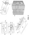
- apparatus 2 for tracking the position of at least one person 4 in a structure in the form of a building 6.
- the apparatus 2 comprises position-identifying means 8 for being worn by the person 4.
- the apparatus 2 further comprises a plurality of position-determining devices in the form of radio frequency identification (RFID) devices 10.
- RFID devices 10 are positioned at positions throughout the building 6 at which the person 4 must pass in order to move about the building 6.
- the apparatus 2 further comprises monitor means 12 for monitoring the position of the person 4 in the building 6.
- the apparatus 2 is such that the RFID devices 10 emit pulses which are able to be received by the position-identifying means 8.
- Each RFID device 10 emits pulses which only travel a short distance which is in the vicinity of the RFID device. Thus, as the person 4 walks about the building 6, the RFID devices 10 are in radio communication one at a time with the position-identifying means 8.
- the position-identifying means 8 is in radio contact with the monitor means 12.
- the monitor means 12 includes a plan of the building 6, and the position of the RFID devices 10.
- the radio communication of the RFID devices 10 one at a time with the position-identifying means 8 enables the monitor means 12 to track the position of the person 4 as the person 4 walks about the building, with the position of the person 4 being determinable as being in the vicinity of each RFID device 10 as it becomes in radio contact with the position-identifying means 8.
- the position-identifying means 8 includes an inertial measurement unit 14.
- the position-identifying means 8 is constructed for being worn on a part of the person 4 that enables the inertial measurement unit 14 to measure the gait of the person as the person is walking, whereby the inertial measurement unit 14 is able to indicate via the monitor means 12 a more exact position of the person 4 relative to each RFID device 10, and also the direction of movement of the person 4 relative to each RFID device 10.
- the inertial measurement unit 14 comprises a gyroscope 16, an accelerometer 18, and an altimeter 22.
- the position-identifying means 8 is such that it includes compass means 41 which is compensated for magnetic distortion in the structure and which operates to correct any directional drift accumulated by the inertial measurement unit 14 over time.
- the compass means 41 takes readings when stable direction measurements are obtained in the structure.
- the inertial measurement unit 14 has its own battery for providing electrical power for the inertial measurement unit 14.
- the combination of the RFID devices 10 and the inertial measurement unit 14 enables the monitor means 12 to show on the building plans the position and direction of movement of the person 4.
- the RFID devices 10 give the coarse position of the person 4.
- the inertial measurement unit 14 measures the person's walking gait and gives the precise position of the person 4 and also the direction of movement of the person 4.
- the inertial measurement unit 14 may not be able to determine its position in the building.
- the RFID devices 10 tell the inertial measurement unit 14 where it is in the building by virtue of the sequential contact of the RFID devices 10 with the inertial measurement unit 14.
- the RFID devices 10 correct any drifting of perceived location of the inertial measurement unit 14.
- the drifting of the inertial measurement unit 14 may be due to it relying on a gyroscope and an accelerometer, and/or due to different persons having different walking gaits.
- the inertial measurement unit 14 uses the accelerometer for measuring the speed of the person 4, and the gyroscope for measuring the direction of the person 4.
- the radio frequency unit 14 is in effect re-set continuously via each RFID device 10.
- the apparatus 2 is able accurately to track the person 4 for long periods of time, for example for periods of more than eight hours which is a normal working day.
- the building plan or plans have a geographic co-ordinate system.
- the radio communication of the RFID devices 10 with the position-identifying means 8 is via Bluetooth.
- Bluetooth provides a convenient wireless technology standard for exchanging required data over short distances, for example using short wavelength radio waves in the ISM band of from 2.4 - 2.485 GHz.
- the pulses emitted by the RFID devices 10 may travel a distance of not more than approximately 1-10 metres, for example 2 metres.
- the RFID devices 10 are positioned at doorways 24, halls 26, lifts, or other positions throughout the building 6 at which the person 4 must pass in order to move about the building 6.
- the position-identifying means 8 includes not only the inertial measurement unit 14 and the compass means 41 but also a mini computer 28, a battery pack 30 and a radio transmitter 32.
- the battery pack 30 provides the required power for various parts of the position-identifying means 8.
- the mini computer 28, the battery pack 30, the radio transmitter 32 and the compass means 41 are worn as a unit 34 which is attached to a belt 36 worn by the person 4.
- the inertial measurement unit 14 is in communication with the mini computer 28 as shown schematically in Figure 1 .
- the radio transmitter 32 communicates with a radio transmitter 38. Because the radio transmitter 32, 38 are in wireless connection with each other minimal cost is involved.
- the modem radio 38 communicates with the control means 12 and may form part of the control means 12. Connections between the various parts of the apparatus as shown in Figure 1 are via Wi-Fi 40 as shown.
- the Wi-Fi 40 can be used to triangulate the position of the person 4 at any one time in the building 6.
- the apparatus 2 can be independent of mobile and satellite network operators. If there is a power failure, the apparatus 2 can still continue to function.
- the inertial measurement unit 14 is in the form of a device which is worn on the person 4, for example on a shoe 42 of the person 4.
- the wearing of the inertial measurement unit 14 on the shoe 42 assists in the inertial measurement unit 14 enabling the control means 12 to show not only the position of the person 4 in the building 6, but also to provide movement and trajectory tracking data for the person 4.
- the inertial measurement unit 14 may be worn such that it is on the person's hip or the small of their back.
- the compass means 41 is compensated for magnetic distortion in the building 6. More specifically, the compass means 41 has hard and soft iron magnetisable compensation parts which help to avoid magnet distortion in indoor environments in which the apparatus 2 is operating.
- the compass means 41 is such that it operates to correct any directional drift accumulated by the inertial measurement unit 14 one time.
- the compass means 41 also includes tilt compensating means.
- the tilt compensation adjusts the magnetic sensor in the compass means 41 for pitch and roll of the unit 34 caused by the person walking in the building 6.
- Figure 2 also shows how the person 4 may be at an arbitrary location 46 on the sixth floor of the building 6. n the arbitrary location 46, the person 4 may be walking through cubicles 48 located to one side of an open office space 50. The path that the person 4 has walked is shown as path 52. Two of the cubicles 48 are shown with the RFID devices 10.
- a control room 54 may be located where desired in the building 6, for example at the illustrated position 56. In the control room 54, an operator 58 is able to see the person 4 and the path 52 on a monitoring screen 60.
- the apparatus 2 is easily and cheaply produced.
- the apparatus 2 is also easily maintained.
- the apparatus 2 does not require expensive visual display units.
- the RFID devices 10 are easily located, as can be appreciated from Figure 2 which shows a RFID device 10 located above a threshold of a door 44.
- the various parts of the apparatus 2 communicate in a wireless manner, which again facilitates ease and cheapness of installation.
- the inertial measurement unit 14 enables the position of the person 4 in the building 6 to be continuously tracked, and substantially irrespective of the construction of the building surrounding the person 4 at the time of the tracking.
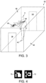
- FIG. 3 there is shown part of apparatus 62 of the present invention. Similar parts as in previous Figures have been given the same reference numerals for ease of comparison and understanding.
- Figure 3 shows the use of orientation re-alignment means in the form of a plurality of fiducial markers 64, only one of which is shown for ease of illustration.
- a fiducial marker 64 is shown on a ceiling 66 of a room or cubicle 48 having two doorways 24.
- the person 4 is wearing a camera 68.
- the fiducial markers 64 can be placed where desired on appropriate parts of a structure in the form of a building such for example as the building 6.
- the fiducial markers 64 re-align drift orientation errors occurred by the inertial measurement unit 14 on the shoe 42 of the person 4, and also as occurred by the monitor means 12.
- the camera 68 is worn as shown on the body of the person 4. With the appropriate computer software in the camera 68, the camera 68 is able to enable recognise the fiducial markers 64.
- the fiducial markers 64 act as reference points.
- the reference points may be regarded as fixed points or lines within a scene to which other objects can be related, or against which objects can be measured.
- the camera 68 is able to recognise the fiducial markers 64 through a process of collimation.
- the camera 68 is then able to be used to re-align the internal measurement means as required to the correct axis/orientation.
- Figure 4 shows two fiducial markers 70, 72 which are shown as examples of fiducial markers that may be used in the apparatus 62.
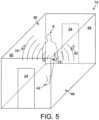
- FIG. 5 there is shown part of apparatus 74 of the present invention. Similar parts as in previous Figures have been given the same reference numerals for ease of comparison and understanding.
- the person 4 is shown wearing a three-axis fluxgate magnetometer sensor 76 on their hip.
- a reference sensor in the form of a three-axis fluxgate magnetometer 78 is mounted on a wall 80 of the room or cubical 48.
- Another reference sensor in the form of a three-axis fluxgate magnetometer 82 is mounted on an opposite wall 84.
- the apparatus 74 is able to operate as an alternative to the apparatus 62 shown in Figure 3 . More specifically, the apparatus 74 is able to operate to provide re-alignment of orientation for the inertial measurement unit 14 and which may be in the form of a device (not shown) which is worn on the shoe 42 of the person 4. Alternatively or in addition, the apparatus 74 is able to provide for the re-alignment of orientation of the monitor means 12. More specifically, a reference of orientation to the person 4 is able to be obtained using the sensors in the form of the three-axis fluxgate magnetometer sensor 76 mounted on the hip of the person 4 from the wall-mounted reference three-axis fluxgate magnetometer sensors 78, 82 mounted on the walls 80, 84 respectively.
- the magnetometers 78, 82 have their axes aligned with geographic north, then this provides a physical and constant reference that is not subject to change. If the reference sensor 76 were to be fixed horizontally to geographic north, then the readings from this reference sensor 76 represent the position of the earth's field at that location relative to a physical orientation. Due to the physical alignment, the apparatus 74 can correlate with the measurements from the sensor 76 mounted on the person 4. The sensor 76 mounted on the person 4 would be orientated on every person 4 in a consist way in order to correlate field readings with a heading of the person.
- the RFID devices 10 may alternatively be position-determining devices in the form of passive infrared devices, or position-determining devices in the form of WiFi enabled devices.
- the unit 34 may be worn by the person 4 at a position other than on their belt 36.
- the inertial measurement unit 14 may be worn or mounted on the person 4 other than on their shoe 42.
- As many parts as required may be formed as a miniaturised package for being worn wherever desired on the person 4.
- As many persons 4 as suitable and required may be tracked using the apparatus of the invention.
- the person 4 may be persons working in working conditions which render the persons 4 vulnerable, for example as occurs in nuclear and petro-chemical buildings, mines, oil refineries, and high security Government complexes.
- the apparatus of the present invention enables security personnel to know that workers are safe, and without the workers having to report in.
- the wording on the drawings is given for the purpose of enabling the drawings easily to be understood, and the wording is not to be interpreted in a limiting manner. Individual components shown in the drawings are not limited to use in their drawings and they may be used in other drawings and in all aspects of the invention.
Landscapes
- Engineering & Computer Science (AREA)
- Radar, Positioning & Navigation (AREA)
- Remote Sensing (AREA)
- Physics & Mathematics (AREA)
- General Physics & Mathematics (AREA)
- Automation & Control Theory (AREA)
- Electromagnetism (AREA)
- Position Fixing By Use Of Radio Waves (AREA)
Claims (12)
- Appareil pour suivre la position d'au moins une personne déambulant dans une structure (6),lequel appareil comprend :(i) des moyens d'identification de position (8) destinés à être portés par la personne :(ii) une pluralité de dispositifs de détermination de position destinés à être disposés à des positions fixes connues dans toute la structure (6) au niveau desquelles la personne doit passer afin de se déplacer à travers la structure ;(iii) des moyens de surveillance (12) destinés à surveiller la position d'une personne dans une structure ; et(iv) des moyens de réalignement d'orientation destinés à réaligner des erreurs d'orientation de dérive survenues par les moyens d'identification de position et/ou les moyens de surveillance ;et l'appareil étant tel que :(v) les dispositifs de détermination de position émettent des signaux qui sont en mesure d'être reçus par les moyens d'identification de position (8) ;(vi) chaque dispositif de détermination de position émet des signaux qui parcourent uniquement une distance qui se trouve à proximité du dispositif de détermination de position, moyennant quoi, tandis que la personne déambule dans la structure (6), les dispositifs de détermination de position sont en communication radio un à la fois avec les moyens d'identification de position ;(vii) les moyens d'identification de position (8) sont en contact radio avec les moyens de surveillance (12) ;(viii) les moyens de surveillance (12) comprennent un plan de la structure (6) et de la position des dispositifs de détermination de position, moyennant quoi la communication radio des dispositifs de détermination de position un à la fois avec les moyens d'identification de position (8) permettent aux moyens de surveillance de suivre la position de la personne tandis que celle-ci déambule dans la structure (6), avec la position de la personne pouvant être déterminée comme étant à proximité de chaque dispositif de détermination de position tandis qu'il entre en communication radio avec les moyens d'identification de position (8) ;(ix) les moyens d'identification de position (8) comprennent une unité de mesure inertielle (14) ; et(x) les moyens d'identification de position (8) sont conçus pour être portés sur la personne afin de permettre à l'unité de mesure inertielle de mesurer l'allure de la personne tandis qu'elle déambule ;(xi) les moyens de réalignement d'orientation sont :une pluralité de marqueurs de repère (64), qui agissent comme des points de référence, dans lequel les points de référence sont des points ou des lignes fixes dans une scène auxquels d'autres objets sont liés ou par rapport auxquels des objets sont mesurés, dans lequel en outre une caméra (68) est utilisée pour reconnaître les marqueurs de repère (64) par un processus de collimation, et dans lequel les moyens de réalignement réalignent les moyens de surveillance (12), avec le réalignement étant sur l'axe/l'orientation correct ; ouune pluralité d'aimants, dans lequel une référence d'orientation est fournie à un capteur magnétométrique à fluxgate à trois axes (76) monté sur la personne, à partir d'un magnétomètre à fluxgate à trois axes de capteur de référence mural (78, 82) avec des axes alignés avec le Nord géographique ;(xii) l'unité de mesure inertielle (14) fournit une position de la personne par rapport à chaque dispositif de détermination de position, ainsi que la direction de déplacement de la personne par rapport à chaque dispositif de détermination de position ; et(xiii) la dérive de précision des mesures effectuées par l'unité de mesure inertielle (14) pendant des périodes de surveillance prolongées est évitée par le fait que les dispositifs de détermination de position entrent en communication avec l'unité de mesure inertielle (14), et donc la précision de l'unité de mesure inertielle (14) peut être maintenue pendant de longues périodes de surveillance.
- Appareil selon la revendication 1, dans lequel les dispositifs de détermination de position sont des dispositifs infrarouges passifs.
- Appareil selon la revendication 1, dans lequel les dispositifs de détermination de position sont des dispositifs d'identification par radiofréquence, RFID (10).
- Appareil selon la revendication 1, dans lequel les dispositifs de détermination de position sont des dispositifs compatibles Wi-Fi (40).
- Appareil selon l'une quelconque des revendications précédentes dans lequel l'unité de mesure inertielle comprend un gyroscope (16) et un accéléromètre (18).
- Appareil selon l'une quelconque des revendications précédentes, dans lequel la communication radio des dispositifs de détermination de position avec les moyens d'identification de position s'effectue via Bluetooth.
- Appareil selon l'une quelconque des revendications précédentes, dans lequel les signaux émis par les dispositifs de détermination de position parcourent une distance ne dépassant pas environ 1 à 10 mètres.
- Appareil selon l'une quelconque des revendications précédentes, dans lequel les signaux émis par les dispositifs de détermination de position se déplacent dans un rayon.
- Appareil selon l'une quelconque des revendications précédentes, dans lequel les dispositifs de détermination de position sont positionnés au niveau des portes, ascenseurs, halls et couloirs de la structure (6).
- Appareil selon l'une quelconque des revendications précédentes, dans lequel les moyens d'identification de position sont adaptés pour être portés sur ou comme partie d'une ceinture (36) ou d'un article chaussant (42).
- Appareil selon l'une quelconque des revendications précédentes, dans lequel les moyens d'identification de position comprennent des moyens d'attache pour attacher les moyens d'identification de position à un article vestimentaire.
- Appareil selon l'une quelconque des revendications précédentes dans lequel le plan de la structure comprend un système de coordonnées géographiques.
Applications Claiming Priority (2)
| Application Number | Priority Date | Filing Date | Title |
|---|---|---|---|
| GB201408621A GB201408621D0 (en) | 2014-05-14 | 2014-05-14 | Apparatus for traking the position of at least one person walking about a structure |
| PCT/GB2015/000117 WO2015173534A1 (fr) | 2014-05-14 | 2015-04-13 | Appareil de suivi de position d'au moins une personne marchant autour d'une structure |
Publications (3)
| Publication Number | Publication Date |
|---|---|
| EP3143423A1 EP3143423A1 (fr) | 2017-03-22 |
| EP3143423B1 true EP3143423B1 (fr) | 2023-11-29 |
| EP3143423C0 EP3143423C0 (fr) | 2023-11-29 |
Family
ID=51032813
Family Applications (1)
| Application Number | Title | Priority Date | Filing Date |
|---|---|---|---|
| EP15717197.6A Active EP3143423B1 (fr) | 2014-05-14 | 2015-04-13 | Appareil de suivi de position d'au moins une personne marchant autour d'une structure |
Country Status (4)
| Country | Link |
|---|---|
| US (1) | US10228442B2 (fr) |
| EP (1) | EP3143423B1 (fr) |
| GB (1) | GB201408621D0 (fr) |
| WO (1) | WO2015173534A1 (fr) |
Families Citing this family (5)
| Publication number | Priority date | Publication date | Assignee | Title |
|---|---|---|---|---|
| WO2017151734A1 (fr) * | 2016-03-01 | 2017-09-08 | Mirus Llc | Systèmes et procédés de suivi de position et d'orientation d'anatomie et d'instruments chirurgicaux |
| GB2560510B (en) * | 2017-03-12 | 2020-09-23 | Data Collaboration Systems Ltd | An RFID Monitoring System |
| IT201800009458A1 (it) * | 2018-10-15 | 2020-04-15 | Christian Canino | Sistema di monitoraggio di operatori in un edificio e relativo procedimento |
| CN109556602B (zh) * | 2018-10-30 | 2021-02-05 | 何学苗 | 一种惯性导航方法、设备及计算机可读存储介质 |
| CN109751997A (zh) * | 2018-12-26 | 2019-05-14 | 南京威惯传感科技有限公司 | 一种结合rfid标定的自主行人惯性定位系统 |
Family Cites Families (10)
| Publication number | Priority date | Publication date | Assignee | Title |
|---|---|---|---|---|
| US6651003B2 (en) | 2001-07-30 | 2003-11-18 | Innovative Design Solutions, Inc. | Method of automatic continuous calibration for an electric compass |
| KR100532589B1 (ko) | 2003-12-26 | 2005-12-01 | 한국전자통신연구원 | 무선인식/위성측위/관성항법을 결합한 통합 측위 장치 및그 방법 |
| US20130162481A1 (en) * | 2009-10-01 | 2013-06-27 | Parviz Parvizi | Systems and methods for calibration of indoor geolocation |
| US8659429B1 (en) | 2010-04-09 | 2014-02-25 | Bae Systems Information And Electronic Systems Integration Inc. | In-building location system |
| US8174931B2 (en) * | 2010-10-08 | 2012-05-08 | HJ Laboratories, LLC | Apparatus and method for providing indoor location, position, or tracking of a mobile computer using building information |
| US9086470B2 (en) * | 2011-11-29 | 2015-07-21 | Shalom Daskal | Method and apparatus for mapping buildings |
| US10082584B2 (en) * | 2012-06-21 | 2018-09-25 | Microsoft Technology Licensing, Llc | Hybrid device location determination system |
| US10360760B2 (en) * | 2012-06-22 | 2019-07-23 | Zonal Systems, Llc | System and method for placing virtual geographic zone markers |
| ES2676552T3 (es) * | 2012-07-02 | 2018-07-20 | Locoslab Gmbh | Método para usar y generar un mapa |
| US20180240176A1 (en) * | 2017-02-21 | 2018-08-23 | Panasonic Intellectual Property Management Co., Ltd. | Electronic routing and messaging in a venue based on activity level |
-
2014
- 2014-05-14 GB GB201408621A patent/GB201408621D0/en not_active Ceased
-
2015
- 2015-04-13 EP EP15717197.6A patent/EP3143423B1/fr active Active
- 2015-04-13 US US15/310,517 patent/US10228442B2/en active Active
- 2015-04-13 WO PCT/GB2015/000117 patent/WO2015173534A1/fr not_active Ceased
Also Published As
| Publication number | Publication date |
|---|---|
| EP3143423A1 (fr) | 2017-03-22 |
| US20170074967A1 (en) | 2017-03-16 |
| WO2015173534A1 (fr) | 2015-11-19 |
| GB201408621D0 (en) | 2014-06-25 |
| EP3143423C0 (fr) | 2023-11-29 |
| US10228442B2 (en) | 2019-03-12 |
Similar Documents
| Publication | Publication Date | Title |
|---|---|---|
| AU2021201818B2 (en) | Tracking and accountability device and system | |
| EP3143423B1 (fr) | Appareil de suivi de position d'au moins une personne marchant autour d'une structure | |
| US10064012B1 (en) | Multi-floor and multi-building ultra-wideband (UWB) location device, system, and method | |
| US8279062B2 (en) | Tracking system and methods thereof | |
| US10782135B2 (en) | Magnetic beacon and inertial sensor localization technology | |
| AU2007348326B2 (en) | Method and system for locating and monitoring first responders | |
| US8179253B2 (en) | Location and tracking system, method and device using wireless technology | |
| Bertuletti et al. | Indoor distance estimated from Bluetooth Low Energy signal strength: Comparison of regression models | |
| Faramondi et al. | An enhanced indoor positioning system for first responders | |
| WO2015086062A1 (fr) | Procédé de positionnement d'humains et de dispositifs dans des environnements souterrains | |
| Simon et al. | Indoor localization system for emergency responders with ultra low-power radio landmarks | |
| Janczak et al. | Indoor positioning based on Bluetooth RSSI mean estimator for the evacuation supervision system application | |
| Stromback et al. | Foot-mounted inertial navigation and cooperative sensor fusion for indoor positioning | |
| CN111007459A (zh) | 一种动态拓扑定位方法 | |
| Syberfeldt et al. | Localizing operators in the smart factory: A review of existing techniques and systems | |
| Fink et al. | RSSI-based indoor positioning using diversity and Inertial Navigation | |
| Xia et al. | A novel PDR aided UWB indoor positioning method | |
| Rozum et al. | Bluetooth low power portable indoor positioning system using simo approach | |
| CN102183254B (zh) | 基于惯性测量单元和无线电低频技术的煤矿定位和通信系统 | |
| AU2015201877B2 (en) | Method and system for locating and monitoring first responders | |
| CN101694391A (zh) | 步行导航仪 | |
| KR20250083187A (ko) | 위치 기반 관리 시스템 및 그 동작 방법 | |
| US9858791B1 (en) | Tracking and accountability device and system | |
| Kemppi et al. | Use of artificial magnetic anomalies in indoor pedestrian navigation | |
| CN104698434A (zh) | 一种基于超宽带的室内应急定位方法 |
Legal Events
| Date | Code | Title | Description |
|---|---|---|---|
| STAA | Information on the status of an ep patent application or granted ep patent |
Free format text: STATUS: THE INTERNATIONAL PUBLICATION HAS BEEN MADE |
|
| PUAI | Public reference made under article 153(3) epc to a published international application that has entered the european phase |
Free format text: ORIGINAL CODE: 0009012 |
|
| STAA | Information on the status of an ep patent application or granted ep patent |
Free format text: STATUS: REQUEST FOR EXAMINATION WAS MADE |
|
| 17P | Request for examination filed |
Effective date: 20161210 |
|
| AK | Designated contracting states |
Kind code of ref document: A1 Designated state(s): AL AT BE BG CH CY CZ DE DK EE ES FI FR GB GR HR HU IE IS IT LI LT LU LV MC MK MT NL NO PL PT RO RS SE SI SK SM TR |
|
| AX | Request for extension of the european patent |
Extension state: BA ME |
|
| DAV | Request for validation of the european patent (deleted) | ||
| DAX | Request for extension of the european patent (deleted) | ||
| STAA | Information on the status of an ep patent application or granted ep patent |
Free format text: STATUS: EXAMINATION IS IN PROGRESS |
|
| 17Q | First examination report despatched |
Effective date: 20200417 |
|
| RIC1 | Information provided on ipc code assigned before grant |
Ipc: G01C 21/20 20060101ALI20230524BHEP Ipc: G01C 21/16 20060101ALI20230524BHEP Ipc: G01S 5/02 20100101AFI20230524BHEP |
|
| GRAP | Despatch of communication of intention to grant a patent |
Free format text: ORIGINAL CODE: EPIDOSNIGR1 |
|
| STAA | Information on the status of an ep patent application or granted ep patent |
Free format text: STATUS: GRANT OF PATENT IS INTENDED |
|
| RAP3 | Party data changed (applicant data changed or rights of an application transferred) |
Owner name: EDWARDS, STUART GRAHAM |
|
| RIN1 | Information on inventor provided before grant (corrected) |
Inventor name: EDWARDS, STUART GRAHAM |
|
| INTG | Intention to grant announced |
Effective date: 20230712 |
|
| GRAJ | Information related to disapproval of communication of intention to grant by the applicant or resumption of examination proceedings by the epo deleted |
Free format text: ORIGINAL CODE: EPIDOSDIGR1 |
|
| STAA | Information on the status of an ep patent application or granted ep patent |
Free format text: STATUS: EXAMINATION IS IN PROGRESS |
|
| GRAS | Grant fee paid |
Free format text: ORIGINAL CODE: EPIDOSNIGR3 |
|
| STAA | Information on the status of an ep patent application or granted ep patent |
Free format text: STATUS: GRANT OF PATENT IS INTENDED |
|
| GRAP | Despatch of communication of intention to grant a patent |
Free format text: ORIGINAL CODE: EPIDOSNIGR1 |
|
| GRAA | (expected) grant |
Free format text: ORIGINAL CODE: 0009210 |
|
| STAA | Information on the status of an ep patent application or granted ep patent |
Free format text: STATUS: THE PATENT HAS BEEN GRANTED |
|
| INTC | Intention to grant announced (deleted) | ||
| INTG | Intention to grant announced |
Effective date: 20231012 |
|
| AK | Designated contracting states |
Kind code of ref document: B1 Designated state(s): AL AT BE BG CH CY CZ DE DK EE ES FI FR GB GR HR HU IE IS IT LI LT LU LV MC MK MT NL NO PL PT RO RS SE SI SK SM TR |
|
| REG | Reference to a national code |
Ref country code: GB Ref legal event code: FG4D |
|
| REG | Reference to a national code |
Ref country code: CH Ref legal event code: EP |
|
| REG | Reference to a national code |
Ref country code: DE Ref legal event code: R096 Ref document number: 602015086720 Country of ref document: DE |
|
| REG | Reference to a national code |
Ref country code: IE Ref legal event code: FG4D |
|
| U01 | Request for unitary effect filed |
Effective date: 20231222 |
|
| U07 | Unitary effect registered |
Designated state(s): AT BE BG DE DK EE FI FR IT LT LU LV MT NL PT SE SI Effective date: 20240108 |
|
| PG25 | Lapsed in a contracting state [announced via postgrant information from national office to epo] |
Ref country code: GR Free format text: LAPSE BECAUSE OF FAILURE TO SUBMIT A TRANSLATION OF THE DESCRIPTION OR TO PAY THE FEE WITHIN THE PRESCRIBED TIME-LIMIT Effective date: 20240301 |
|
| PG25 | Lapsed in a contracting state [announced via postgrant information from national office to epo] |
Ref country code: IS Free format text: LAPSE BECAUSE OF FAILURE TO SUBMIT A TRANSLATION OF THE DESCRIPTION OR TO PAY THE FEE WITHIN THE PRESCRIBED TIME-LIMIT Effective date: 20240329 |
|
| PG25 | Lapsed in a contracting state [announced via postgrant information from national office to epo] |
Ref country code: ES Free format text: LAPSE BECAUSE OF FAILURE TO SUBMIT A TRANSLATION OF THE DESCRIPTION OR TO PAY THE FEE WITHIN THE PRESCRIBED TIME-LIMIT Effective date: 20231129 |
|
| PG25 | Lapsed in a contracting state [announced via postgrant information from national office to epo] |
Ref country code: IS Free format text: LAPSE BECAUSE OF FAILURE TO SUBMIT A TRANSLATION OF THE DESCRIPTION OR TO PAY THE FEE WITHIN THE PRESCRIBED TIME-LIMIT Effective date: 20240329 Ref country code: GR Free format text: LAPSE BECAUSE OF FAILURE TO SUBMIT A TRANSLATION OF THE DESCRIPTION OR TO PAY THE FEE WITHIN THE PRESCRIBED TIME-LIMIT Effective date: 20240301 Ref country code: ES Free format text: LAPSE BECAUSE OF FAILURE TO SUBMIT A TRANSLATION OF THE DESCRIPTION OR TO PAY THE FEE WITHIN THE PRESCRIBED TIME-LIMIT Effective date: 20231129 |
|
| U20 | Renewal fee for the european patent with unitary effect paid |
Year of fee payment: 10 Effective date: 20240416 |
|
| PG25 | Lapsed in a contracting state [announced via postgrant information from national office to epo] |
Ref country code: RS Free format text: LAPSE BECAUSE OF FAILURE TO SUBMIT A TRANSLATION OF THE DESCRIPTION OR TO PAY THE FEE WITHIN THE PRESCRIBED TIME-LIMIT Effective date: 20231129 Ref country code: PL Free format text: LAPSE BECAUSE OF FAILURE TO SUBMIT A TRANSLATION OF THE DESCRIPTION OR TO PAY THE FEE WITHIN THE PRESCRIBED TIME-LIMIT Effective date: 20231129 Ref country code: NO Free format text: LAPSE BECAUSE OF FAILURE TO SUBMIT A TRANSLATION OF THE DESCRIPTION OR TO PAY THE FEE WITHIN THE PRESCRIBED TIME-LIMIT Effective date: 20240229 Ref country code: HR Free format text: LAPSE BECAUSE OF FAILURE TO SUBMIT A TRANSLATION OF THE DESCRIPTION OR TO PAY THE FEE WITHIN THE PRESCRIBED TIME-LIMIT Effective date: 20231129 |
|
| PG25 | Lapsed in a contracting state [announced via postgrant information from national office to epo] |
Ref country code: CZ Free format text: LAPSE BECAUSE OF FAILURE TO SUBMIT A TRANSLATION OF THE DESCRIPTION OR TO PAY THE FEE WITHIN THE PRESCRIBED TIME-LIMIT Effective date: 20231129 |
|
| PG25 | Lapsed in a contracting state [announced via postgrant information from national office to epo] |
Ref country code: SK Free format text: LAPSE BECAUSE OF FAILURE TO SUBMIT A TRANSLATION OF THE DESCRIPTION OR TO PAY THE FEE WITHIN THE PRESCRIBED TIME-LIMIT Effective date: 20231129 |
|
| PG25 | Lapsed in a contracting state [announced via postgrant information from national office to epo] |
Ref country code: SM Free format text: LAPSE BECAUSE OF FAILURE TO SUBMIT A TRANSLATION OF THE DESCRIPTION OR TO PAY THE FEE WITHIN THE PRESCRIBED TIME-LIMIT Effective date: 20231129 Ref country code: SK Free format text: LAPSE BECAUSE OF FAILURE TO SUBMIT A TRANSLATION OF THE DESCRIPTION OR TO PAY THE FEE WITHIN THE PRESCRIBED TIME-LIMIT Effective date: 20231129 Ref country code: RO Free format text: LAPSE BECAUSE OF FAILURE TO SUBMIT A TRANSLATION OF THE DESCRIPTION OR TO PAY THE FEE WITHIN THE PRESCRIBED TIME-LIMIT Effective date: 20231129 Ref country code: CZ Free format text: LAPSE BECAUSE OF FAILURE TO SUBMIT A TRANSLATION OF THE DESCRIPTION OR TO PAY THE FEE WITHIN THE PRESCRIBED TIME-LIMIT Effective date: 20231129 |
|
| REG | Reference to a national code |
Ref country code: DE Ref legal event code: R097 Ref document number: 602015086720 Country of ref document: DE |
|
| PLBE | No opposition filed within time limit |
Free format text: ORIGINAL CODE: 0009261 |
|
| STAA | Information on the status of an ep patent application or granted ep patent |
Free format text: STATUS: NO OPPOSITION FILED WITHIN TIME LIMIT |
|
| 26N | No opposition filed |
Effective date: 20240830 |
|
| PG25 | Lapsed in a contracting state [announced via postgrant information from national office to epo] |
Ref country code: MC Free format text: LAPSE BECAUSE OF FAILURE TO SUBMIT A TRANSLATION OF THE DESCRIPTION OR TO PAY THE FEE WITHIN THE PRESCRIBED TIME-LIMIT Effective date: 20231129 |
|
| PG25 | Lapsed in a contracting state [announced via postgrant information from national office to epo] |
Ref country code: MC Free format text: LAPSE BECAUSE OF FAILURE TO SUBMIT A TRANSLATION OF THE DESCRIPTION OR TO PAY THE FEE WITHIN THE PRESCRIBED TIME-LIMIT Effective date: 20231129 |
|
| REG | Reference to a national code |
Ref country code: CH Ref legal event code: PL |
|
| PG25 | Lapsed in a contracting state [announced via postgrant information from national office to epo] |
Ref country code: CH Free format text: LAPSE BECAUSE OF NON-PAYMENT OF DUE FEES Effective date: 20240430 |
|
| PG25 | Lapsed in a contracting state [announced via postgrant information from national office to epo] |
Ref country code: IE Free format text: LAPSE BECAUSE OF NON-PAYMENT OF DUE FEES Effective date: 20240413 |
|
| U20 | Renewal fee for the european patent with unitary effect paid |
Year of fee payment: 11 Effective date: 20250428 |
|
| PGFP | Annual fee paid to national office [announced via postgrant information from national office to epo] |
Ref country code: GB Payment date: 20250414 Year of fee payment: 11 |
|
| PG25 | Lapsed in a contracting state [announced via postgrant information from national office to epo] |
Ref country code: CY Free format text: LAPSE BECAUSE OF FAILURE TO SUBMIT A TRANSLATION OF THE DESCRIPTION OR TO PAY THE FEE WITHIN THE PRESCRIBED TIME-LIMIT; INVALID AB INITIO Effective date: 20150413 |
|
| PG25 | Lapsed in a contracting state [announced via postgrant information from national office to epo] |
Ref country code: HU Free format text: LAPSE BECAUSE OF FAILURE TO SUBMIT A TRANSLATION OF THE DESCRIPTION OR TO PAY THE FEE WITHIN THE PRESCRIBED TIME-LIMIT; INVALID AB INITIO Effective date: 20150413 |