EP3143633B1 - Dispositif de commutation pour interrupteur sans fil, interrupteur sans fil et procédé de génération d'un signal de commutation d'un interrupteur sans fil - Google Patents
Dispositif de commutation pour interrupteur sans fil, interrupteur sans fil et procédé de génération d'un signal de commutation d'un interrupteur sans fil Download PDFInfo
- Publication number
- EP3143633B1 EP3143633B1 EP15718831.9A EP15718831A EP3143633B1 EP 3143633 B1 EP3143633 B1 EP 3143633B1 EP 15718831 A EP15718831 A EP 15718831A EP 3143633 B1 EP3143633 B1 EP 3143633B1
- Authority
- EP
- European Patent Office
- Prior art keywords
- switching
- carriage
- radio
- energy
- converter device
- Prior art date
- Legal status (The legal status is an assumption and is not a legal conclusion. Google has not performed a legal analysis and makes no representation as to the accuracy of the status listed.)
- Active
Links
Images






Classifications
-
- H—ELECTRICITY
- H01—ELECTRIC ELEMENTS
- H01H—ELECTRIC SWITCHES; RELAYS; SELECTORS; EMERGENCY PROTECTIVE DEVICES
- H01H23/00—Tumbler or rocker switches, i.e. switches characterised by being operated by rocking an operating member in the form of a rocker button
- H01H23/02—Details
- H01H23/12—Movable parts; Contacts mounted thereon
- H01H23/14—Tumblers
- H01H23/143—Tumblers having a generally flat elongated shape
-
- H—ELECTRICITY
- H02—GENERATION; CONVERSION OR DISTRIBUTION OF ELECTRIC POWER
- H02K—DYNAMO-ELECTRIC MACHINES
- H02K35/00—Generators with reciprocating, oscillating or vibrating coil system, magnet, armature or other part of the magnetic circuit
-
- H—ELECTRICITY
- H01—ELECTRIC ELEMENTS
- H01H—ELECTRIC SWITCHES; RELAYS; SELECTORS; EMERGENCY PROTECTIVE DEVICES
- H01H2239/00—Miscellaneous
- H01H2239/076—Key stroke generating power
-
- H—ELECTRICITY
- H01—ELECTRIC ELEMENTS
- H01H—ELECTRIC SWITCHES; RELAYS; SELECTORS; EMERGENCY PROTECTIVE DEVICES
- H01H2300/00—Orthogonal indexing scheme relating to electric switches, relays, selectors or emergency protective devices covered by H01H
- H01H2300/03—Application domotique, e.g. for house automation, bus connected switches, sensors, loads or intelligent wiring
-
- H—ELECTRICITY
- H01—ELECTRIC ELEMENTS
- H01H—ELECTRIC SWITCHES; RELAYS; SELECTORS; EMERGENCY PROTECTIVE DEVICES
- H01H9/00—Details of switching devices, not covered by groups H01H1/00 - H01H7/00
- H01H9/16—Indicators for switching condition, e.g. "on" or "off"
- H01H9/168—Indicators for switching condition, e.g. "on" or "off" making use of an electromagnetic wave communication
-
- Y—GENERAL TAGGING OF NEW TECHNOLOGICAL DEVELOPMENTS; GENERAL TAGGING OF CROSS-SECTIONAL TECHNOLOGIES SPANNING OVER SEVERAL SECTIONS OF THE IPC; TECHNICAL SUBJECTS COVERED BY FORMER USPC CROSS-REFERENCE ART COLLECTIONS [XRACs] AND DIGESTS
- Y02—TECHNOLOGIES OR APPLICATIONS FOR MITIGATION OR ADAPTATION AGAINST CLIMATE CHANGE
- Y02B—CLIMATE CHANGE MITIGATION TECHNOLOGIES RELATED TO BUILDINGS, e.g. HOUSING, HOUSE APPLIANCES OR RELATED END-USER APPLICATIONS
- Y02B90/00—Enabling technologies or technologies with a potential or indirect contribution to GHG emissions mitigation
- Y02B90/20—Smart grids as enabling technology in buildings sector
-
- Y—GENERAL TAGGING OF NEW TECHNOLOGICAL DEVELOPMENTS; GENERAL TAGGING OF CROSS-SECTIONAL TECHNOLOGIES SPANNING OVER SEVERAL SECTIONS OF THE IPC; TECHNICAL SUBJECTS COVERED BY FORMER USPC CROSS-REFERENCE ART COLLECTIONS [XRACs] AND DIGESTS
- Y04—INFORMATION OR COMMUNICATION TECHNOLOGIES HAVING AN IMPACT ON OTHER TECHNOLOGY AREAS
- Y04S—SYSTEMS INTEGRATING TECHNOLOGIES RELATED TO POWER NETWORK OPERATION, COMMUNICATION OR INFORMATION TECHNOLOGIES FOR IMPROVING THE ELECTRICAL POWER GENERATION, TRANSMISSION, DISTRIBUTION, MANAGEMENT OR USAGE, i.e. SMART GRIDS
- Y04S20/00—Management or operation of end-user stationary applications or the last stages of power distribution; Controlling, monitoring or operating thereof
- Y04S20/14—Protecting elements, switches, relays or circuit breakers
Definitions
- the present invention relates to a switching device for a wireless push-button, to a radio push-button and to a method for generating a switching signal of a radio push-button, in particular for the field of home automation for surface mounting.
- Wireless pushbuttons are used, for example, as a surface-mounted solution, especially in building services.
- a plurality of consumers can be controlled by a switching signal via wireless pushbutton, such as bulbs, blinds and the like.
- the DE 20 2004 005 837 U1 discloses a switch housing for surface mounting and for receiving an electronic module.
- a switching device for a self-sufficient radio push-button for building technology can be provided, by means of which a switching signal can be generated.
- a switching mechanism or so-called “toggle” mechanism of the switching device depending on the embodiment, that only one energy pulse can be generated in a switching operation or actuation process or two or more energy pulses can be generated.
- the switching mechanism is designed to activate or actuate an energy converter only once in a first embodiment and assembly variant during a switching operation and to activate or actuate the energy converter, for example, twice in a second embodiment and assembly variant during a switching operation.
- the present invention relates to a switching device as defined in claim 1 for a radio button.
- the radio button can be designed to control at least one external device via radio transmission of the switching signal via the switching signal.
- the wireless pushbutton can be designed to be mounted on plaster, for example in building technology.
- the switching device may also be referred to as a switching module.
- the switching device may include mechanical components for activating the energy conversion device.
- the switching device may be configured to actuate the energy conversion device in response to a switching operation in which an external actuating force representing the mechanical energy is transmitted to the switching device.
- the energy conversion device may be configured to convert mechanical energy of the actuation force into electrical energy.
- the energy conversion device can be configured bistable.
- the energy conversion device may have the first stable state and the second stable state.
- the energy conversion device may be configured to perform an actuation movement between the first stable state and the second stable state due to the mechanical energy transmitted to the power wall device by the actuation means and the switching means, thereby generating an electric energy pulse.
- the energy conversion device is designed to be in an actuation movement from the first stable state to the second stable state, generating an electrical energy pulse and generating an electrical energy pulse upon actuation movement from the second stable state to the first stable state.
- the actuating means may be at least one lever element, a lever, double lever, twin lever or the like.
- the switching means may be arranged and configured to be mechanically contactable by the actuating means. Also, the switching means may be mechanically coupled to the energy conversion device.
- the switching means can be designed to transmit the mechanical energy from the actuating means to the energy conversion device during a switching operation or actuating process.
- the switching means may be configured to shift the energy conversion device from the first stable state into the second stable state and additionally or alternatively from the second stable state into the first stable state in a state coupled to the energy converter device.
- the approach described can be advantageously used according to embodiments of the present invention for the realization of a KNX-RF-enabled switch or radio button.
- the energy converter can generate sufficient energy due to the switching mechanism on the one hand when you press the switch and on the other hand, an operating force can be kept as low as possible. Since it may be sufficient in most applications to produce a single energy pulse, thus no unnecessary energy needs to be generated and no unnecessary actuating force applied.
- use in KNX RF radio networks is possible, whereby a power can be obtained independently of a battery or a connection to the power grid. This makes a job flexible and low maintenance.
- disadvantages of many conventional switching devices or switching modules provided as surface-mounted light switches in building technology can be avoided, which among other things are designed so that, for example, an actuation is initiated on one of two movable levers each electromagnetic energy converter activate.
- switching modules usually a housing may be rigid and require a certain amount of space under a button to avoid a collision in a tilting movement of the key.
- one of for example four coding switches is actuated with an additional element of the key.
- an energy pulse is generated and converted into an electronic module in dependence on the already actuated coding switch to a radio signal and sent by radio.
- Such light switches can use an actuating mechanism, in which in each case an energy pulse is inevitably generated both when pressing the button and when releasing the energy pulse when released, for example discarded or used for a telegram repetition, which according to embodiments of the present invention due to the Shifting mechanism can be avoided.
- a problem can be circumvented, which includes that a power of the energy converter to send KNX RF telegrams would be to increase so much that the operating forces and an operating noise would exceed reasonable values.
- a double-click, including double noise which would additionally worsen switch acoustics, can be avoided according to embodiments of the present invention.
- a perceived as getting used to and not always gladly accepted in the market operating concept with two ways can be prevented, in which, for example, a button can be in a middle position and should be pressed up and down, because often a classic button with an actuation point be desired below.
- the switching means of the switching device have a movable carriage which can be mechanically coupled to the energy conversion device and at least one carriage lever which can be actuated by means of the actuation means.
- the at least one carriage lever is configured to move the movable carriage between a first position associated with the first stable state of the energy conversion device and a second position associated with the second stable state of the energy conversion device.
- the switching device may comprise at least one roller or a sliding element which is mechanically coupled to the movable carriage and additionally or alternatively to the at least one carriage lever.
- the sliding element may, for example, be a sliding plate with a sliding surface.
- a sliding block could be used instead of the sliding plate.
- Essential for the sliding element is a sliding surface, by means of which a frictional resistance-reduced sliding movement of the carriage is made possible with a view of the carriage.
- the sliding surface can be dimensioned optimized. In other words, a degree of sliding surface depending on the desired frictional drag reduced sliding movement is arbitrary.
- the sliding surface may further preferably have a frictional resistance-reducing coating.
- the switching means may comprise elastic means adapted to act on the movable carriage to move the movable carriage from the second position to the first position.
- the switching means may comprise the movable carriage, a carriage lever and the elastic means.
- the actuating means may comprise a lever or a single lever or a lever element.
- the carriage lever may be arranged and configured to be actuated by the lever or single lever due to the mechanical energy.
- the movable carriage is movable by the actuated carriage lever from the first to the second position, wherein the elastic means can be compressed, wherein energy for a return movement of the movable carriage can be constructed from the second position to the first position in the elastic means ,
- the switching means may be configured to cause the energy conversion device to generate two electrical energy pulses during a switching operation.
- the switching means may comprise elastic means and two slide levers.
- the elastic means may be formed to bias the carriage levers in a rest position, wherein the movable carriage between the carriage levers can be arranged.
- a first of the carriage levers may be configured to move the movable carriage from the first position to the second position, wherein a second of the carriage levers may be configured to move the movable carriage from the second position to the first position.
- the actuating means may have a double lever or two levers or lever elements.
- the carriage levers may be arranged and configured such that during a switching operation one of the carriage levers is actuated by one of the levers of the actuation means due to the mechanical energy.
- the switching means may be configured to cause the energy conversion device to generate only an electrical energy pulse during a switching operation.
- a two-way module in which the wireless pushbutton is provided for a different actuation movements, can be realized in a simple and cost-effective manner as actuation concept with low actuation force and high yield of electrical energy in a single pulse per switching operation.
- the switching device may comprise at least one return spring, which is designed to bias the actuating means in a rest position.
- the actuating means are designed to be arranged in the rest position in the absence of mechanical energy of a switching operation or in the absence of an actuating force. Thus, a defined starting position can be created for actuation operations.
- the present invention also relates to a radio push-button with an embodiment of the aforementioned switching device; an energy conversion device which is mechanically coupled to the switching means of the switching device and is designed to convert the mechanical energy which can be introduced into the switching device during the switching process into the electrical energy for emitting the switching signal; a circuit carrier having a signal output device for emitting the switching signal, wherein the circuit carrier is electrically conductively connected to the energy conversion device; a housing having at least one housing element, the housing being designed to receive the switching device, the energy converter device and the circuit carrier; and a key for transmitting the mechanical energy to the actuating means of the switching device, wherein the key is attachable to the housing.
- an embodiment of the above-mentioned switching device can be advantageously used or used, in particular, to activate the energy converter device.
- the housing may be configured to allow wall mounting via plaster or other surface mounting of the radio button in a building or the like.
- the circuit carrier may comprise a printed circuit board, a printed circuit board or the like. In this case, the circuit carrier between the energy conversion device and the button can be arranged or arranged.
- the signal output device can be applied to the circuit carrier by means of methods customary in semiconductor technology.
- the signal output device may have an antenna device, in particular an antenna device printed on the circuit carrier.
- the signal output device can be designed to output the switching signal by radio to an interface to a control device and additionally or alternatively to at least one controllable device.
- An electrical contact between the circuit carrier and the energy conversion device can, for. Example, be realized by means of formed on the circuit board SMD spring contacts, which are electrically conductively connected to a circuit board, which is soldered to contact points of the energy conversion device.
- the circuit carrier may have an overmolded stamped grid with spring contacts. This allows the circuit board and associated soldering costs are eliminated. This can bring a further cost advantage and increase the reliability of the contact.
- the signal output device may comprise radio electronics for generating and transmitting a radio signal.
- the radio signal can fulfill the requirements of a predetermined radio protocol.
- the circuit carrier can have at least one coding contact which can be actuated during the switching operation in order to provide a coding signal.
- the coding signal can be transmitted, for example, to the radio electronics, the radio electronics being designed to generate and transmit a radio signal suitable for a predetermined radio protocol based on the coding signal, wherein the radio signal can represent the information underlying the coding signal.
- the signal output device and the at least one coding contact can be arranged on different main surfaces of the circuit carrier.
- the circuit carrier may comprise at least one electrical circuit which is electrically connected to the Codiertagen, the signal output device and the energy conversion device.
- the radio electronics can be designed to be interchangeable.
- the circuit carrier with a first radio electronics can be replaced by a circuit carrier with a second radio electronics, which differs from the first radio electronics.
- the coding contacts can be designed to enable the coding signal to be made available when contacted by the actuating means or the key during a switching operation.
- the circuit carrier can have an electrical coding circuit which is electrically connected to the coding contacts and designed to generate an individual coding signal, depending on which of the coding contacts is contacted by the actuating means or the key.
- the coding signal may represent information as to which of the coding contacts is contacted by the actuating means or the key.
- the actuating means may be formed to actuate the switching means, while at least one of the Kodiertruste is contacted.
- Such an embodiment has the advantage that the wireless pushbutton by replacing the radio electronics not only according to the KNX RF protocol, but according to other radio protocols in different radio bands, eg. B. 868MHz, 915MHz, 2.4GHz, etc., operable and thus can be used very flexibly.
- the actuating means or the radio push-button for contacting the at least one coding contact may have a switching foil with a plurality of switching projections.
- the switching foil can be formed from an elastically deformable material.
- the switching projections may be formed in the form of switching pills, switching nubs or the like and disposed on a main surface of the switching film.
- the switching foil can be arranged or arranged between the key and the circuit carrier.
- the button or the actuating means may be designed to actuate the Codiercrede in a switching operation by means of the switching film.
- the switching projections may be independently or jointly movable in a Codier ein. In this case, the arrangement and number of switching projections can correspond to those of the coding contacts.
- the button may be formed as a rocker, a double rocker or a multi-rocker.
- Such an embodiment has the advantage that different operating concepts for different devices to be switched by selecting a suitable button and suitable choice of the switching means of the switching device can be realized.
- the housing may be at least partially formed of a sound decoupling material for reducing operating noise.
- the radio button may have a sound isolation capsule for sound insulation for the energy conversion device.
- the sound decoupling material may include a material having an elasticity that is higher than an elasticity of a housing material.
- the housing may comprise a two-component housing of a hard material and a soft material.
- the sound decoupling capsule may be formed of the sound decoupling material.
- the energy conversion device can be isolated by means of a rubber capsule as a sound decoupling capsule of housing parts with respect to a vibration propagation. Such an embodiment offers the advantage that a further noise level reduction can be achieved.
- the present invention furthermore relates to a method for generating a switching signal of a radio push-button, the method being executable in conjunction with a radio push-button which has a switching device, an energy converter device for converting mechanical energy into electrical energy and a circuit carrier with a signal output device, wherein the circuit carrier is electrically is conductively connected to the energy conversion device, the process comprising the following steps: Generating at least one electrical energy pulse for emitting the switching signal by means of the switching device and the energy conversion device using a introduced in a switching operation in the switching device mechanical energy, wherein the mechanical energy of actuating means of the switching device and received by mechanically coupled to the actuating means and the energy conversion means switching means on the energy conversion means is transmitted, wherein the switching means are actuated in the switching operation by the actuating means to offset the energy conversion means at least from a first stable state to a second stable state different from the first stable state for generating the at least one electrical energy pulse; and Outputting the switching signal by radio by means of the signal output device
- the method can be advantageously carried out in order to generate a switching signal in conjunction with the radio pushbutton mentioned above or in conjunction with the aforementioned switching device.
- the switch or radio button in the KNX RF radio network can be used, since a high energy yield of the energy converter and a bidirectional radio operation are possible.
- the wireless pushbutton can generate one energy pulse each time it is actuated and, additionally or alternatively, when it is released, and send one radio telegram each.
- This variant can offer an advantage when used with dimmers or when controlling blinds or blinds.
- the switching device can be designed to cause only a generation of an energy pulse when you press and release the radio button to avoid unnecessary effort and disturbing noises. According to embodiments of the present invention, an improvement of the acoustics, feel and noise of the radio button can thus be achieved.
- an autonomous switching module or a self-sufficient wireless pushbutton for universal use in the KNX RF / KNX RF ready network can be provided. It may be possible to use other or customized radio protocols and free radio bands. Also, an operating force and an operating noise can be reduced and a haptic can be improved, for example, designed analogous to wired light switches. It can be a suitability of the wireless push button to control light sources with dimmer and without dimmer and to control blinds and roller blinds can be achieved. Furthermore, a bidirectional radio operation can be made possible at least during a configuration or learning phase of the radio button.
- the switching device can be designed to be similar to a modular system or variant kit for two operating concepts to be converted, with a feasibility as two-way or disposable module can be provided, both concepts can be realized with only moderate conversion. Thus, it can be used with a single button or with a double button or switch or double switch.
- Fig. 1 shows a schematic representation of a wireless pushbutton 100 according to an embodiment of the present invention. Shown are in the representation of Fig. 1 from the wireless pushbutton 100 in this case a housing 110, a key 120, a circuit carrier 130, a signal output device 140, a power conversion device 150, a switching device 160, actuating means 170 and switching means 180. Further, an actuating force F is shown symbolically by an arrow on the key 120, wherein the operating force F represents a mechanical energy in a switching operation.
- the housing 110 has a housing member. According to another embodiment, the housing 110 may also include two or more housing elements. In the housing 110, the circuit carrier 130, the signal output device 140, the energy conversion device 150 and the switching device 160 are accommodated. In this case, the signal output device 140 is arranged on the circuit carrier 130.
- the switching device 160 has the actuating means 170 and the switching means 180.
- the button 120 is attachable to the housing 110 or mounted during operation of the wireless button 100, even if this is in Fig. 1 is not explicitly shown.
- the key 120 is arranged to be movable by the operating force F to contact the actuating means 170 of the switching device 160 and transmit mechanical energy.
- the key 120 is configured to transmit mechanical energy of the actuating force F to the actuating means 170 of the switching device 160.
- the actuating means 170 of the switching device 160 are designed to receive the mechanical energy which can be introduced into the switching device 160 via the key 120 during a switching operation. Further, the actuators 170 are arranged and configured to be responsive to the received mechanical energy to operate the switching means 180.
- the switching means 180 are mechanically coupled to the actuating means 170 and actuated by the actuating means 170. Furthermore, the switching means 180 are mechanically coupled to the energy conversion device 150. The switching means 180 are configured to transfer the mechanical energy from the actuating means 170 to the energy conversion device 150.
- the energy conversion device 150 is mechanically coupled to the switching means 180 of the switching device 160. Furthermore, the energy conversion device 150 is designed to convert the mechanical energy which can be introduced into the switching device 160 during the switching process into electrical energy for emitting a switching signal.
- the switching means 180 are configured to be operable in the switching operation by the actuation means 170 to set the energy conversion means 150 at least from a first stable state to a second stable state different from the first stable state to generate at least one electrical energy pulse ,
- the circuit carrier 130 with the signal output device 140 is arranged between the energy converter device 150 and the key 120.
- the circuit carrier 130 is electrically conductively connected to the energy conversion device 150.
- the signal output device 140 is arranged on a main surface of the circuit carrier 130 facing the energy conversion device 150. In this case, the signal output device 140 is designed to emit or output the switching signal.
- the switching means 180 of the switching device 160 may have a movable carriage mechanically coupled to the energy converter device 150 and at least one carriage lever that can be actuated by the actuating device 170.
- the at least one carriage lever may be formed to the movable carriage between a first position, which is associated with the first stable state of the energy conversion device 150 is to move and a second position, which is associated with the second stable state of the energy conversion device 150.
- the switching means 180 may also have at least one roller which may be mechanically coupled to the movable carriage and additionally or alternatively to the at least one carriage lever.
- the switching means 180 may comprise resilient means which may be adapted to act on the movable carriage to move the movable carriage from the second position to the first position.
- the switching means 180 may comprise elastic means and two slide levers.
- the elastic means may be formed to bias the carriage levers in a rest position, wherein the movable carriage may be arranged between the carriage levers.
- a first of the carriage levers may be configured to move the movable carriage from the first position to the second position, wherein a second one of the carriage levers may be configured to move the movable carriage from the second position to the first position.
- the signal output device 140 may comprise a replaceable radio electronics.
- the circuit carrier 130 may include at least one encoder contact operable in the switching operation to provide a coding signal.
- the button 120 may optionally be formed as a rocker, a double rocker or a multi-rocker.
- the housing 110 may be at least partially formed of a sound decoupling material for reducing operating noise.
- the radio button 100 may include a sound isolation capsule for sound insulation for the energy conversion device 150.
- Fig. 2 shows a flowchart of a method 200 for generating a switching signal of a radio button according to an embodiment of the present invention.
- the method 200 can be implemented in conjunction with a radio push-button comprising a switching device, an energy converter device for converting mechanical energy into electrical energy, and a circuit carrier electrically connected to the energy converter device with a signal output device having.
- the method 200 is in conjunction with the radio button off Fig. 1 . Fig. 3 . Fig. 4 . Fig. 6 .
- Fig. 10 . Fig. 11 and or FIGS. 12A to 12D executable executable.
- the method 200 comprises a step 210 of generating at least one electrical energy pulse for emitting the switching signal by means of the switching device and the energy conversion device using a mechanical energy introduced into the switching device during a switching operation.
- the mechanical energy is absorbed by actuating means of the switching device and transmitted to the energy conversion device by switching means mechanically coupled to the actuating means and to the energy conversion device.
- the switching means are actuated by the actuation means in the switching operation in order to set the energy conversion means at least from a first stable state to a second stable state different from the first stable state in order to generate the at least one electrical energy pulse.
- the method 200 includes a step 220 of outputting the switching signal by radio by means of the signal output device using the at least one electrical energy pulse.
- Fig. 3 shows a perspective view of a wireless button 100 according to an embodiment of the present invention.
- a housing 110 or housing bottom, a cover 310 or housing cover and two actuating levers 370 are shown by the wireless pushbutton 100.
- the wireless pushbutton 100 is a radio push-button such as, for example, the radio push-button Fig. 1 , wherein the radio button 100 in Fig. 3 without a button, but with the lid 310 shown, with the actuating levers 370 representing the actuating means.
- the wireless button 100 is shown in a mated state without a button.
- An overall housing of the wireless pushbutton 100 in this case has two housing elements, the housing 110 and the cover 310.
- the actuation levers 370 partially protrude from the housing 110 and the cover 310.
- the actuating means are formed as the operating lever 370.
- Fig. 4 shows an exploded perspective view of the wireless button Fig. 3 ,
- the housing 110, the circuit carrier 130, the energy conversion device 150 or a bistable energy converter, the switching means 180, the cover 310, actuating means in the form of the two actuating levers 370 or a twin lever, a switching mat or switching foil 430 are shown , a contact plate or auxiliary circuit board 455, two elongated holes 472, due to the illustration, only one of two pins 474, a return spring 476, a movable carriage 482, two carriage levers 484, a tension spring 486 and two rollers 488th
- the operating levers 370 are attachable to the housing 110. Each of the operating levers 370 has a slot 472 and a pin 474. This is due to the presentation, only one of the pin 474 in Fig. 4 recognizable.
- the operating levers 370 function as a twin lever.
- the actuating means on the return spring 476 is designed to save the operating lever 370 in a rest position and exert a counter force against an actuating force on the actuating lever 370 in a switching operation.
- the actuating means on the actuating lever 370 with the slots 472 and the pin 474 and the return spring 476 on.
- the switching foil 430 is arranged between the cover 310 and the circuit carrier 130.
- the auxiliary circuit board 455 is electrically and mechanically connectable to the power conversion device 150 and is disposed adjacent to the power conversion device 150.
- the energy conversion device 150 can be electrically conductively connected to the circuit carrier 130 by means of the auxiliary circuit board 455.
- the switching means 180 comprise the movable carriage 482, the carriage levers 484, the tension spring 486 and the roller 488. At each of the carriage levers 484, a roller 488 is attachable.
- the movable carriage 482 is disposed between the carriage levers 484.
- the carriage levers 484 are attachable to opposite ends of the movable carriage 482.
- the tension spring 486 is mechanically connectable to the carriage levers 484. In this case, the tension spring 486 in the movable carriage 482 is receivable.
- the energy conversion device 150 with the auxiliary circuit board 455, the return spring 476 and the switching means 180 are arranged between the circuit carrier 130 and a bottom portion of the housing 110 facing away from the cover 310.
- the housing 110 and the lid 310 are made of a plastic material by injection molding and designed for a simple injection tool design.
- a soft, noise-damping plastic can be used as the material in order to minimize noise transmission from the energy conversion device 150 to other switch components of the radio push-button 100.
- the actuating lever 370 As an actuating means, the actuating lever 370 or a so-called twin lever is used. Both operating levers 370 are designed so that two identically shaped parts are used. This enables a reduction of tool costs and part price.
- the actuating lever 370 can be arranged to a lever arrangement and rotatably supported in the housing 110 receivable. Here, the actuating lever 370 by means of the slots 472 and pin 474 are connected to each other, wherein both operating lever 370 can be set in motion as soon as one of the two actuating lever is actuated or activated with the actuating force. A provision of the actuating lever 370 by means of the return spring 476.
- a return spring 476 a compression spring, tension spring, torsion spring or a bending spring is used.
- the return spring 476 is shown as a stamped bending spring. A spring force of the return spring 476 is selected so that a reliable return of the operating lever 370 and a button is enabled.
- the switching means 180 are functionally connected in the form of a so-called toggle mechanism.
- the switching means 180 comprise, in particular, the movable carriage 482, which can be received slidingly or rollably mounted in the housing 110 and can be mechanically connected to an actuator of the energy conversion device 150.
- the lid 310 is made for example of a noise-damping plastic.
- the housing 110 can be closed by means of the cover 310.
- the lid 310 has fasteners and a pivot bearing or pivot pin for a button.
- the circuit carrier 130 has an electrical circuit for energy management and the signal output device with a radio electronics and an antenna, even if they are in Fig. 4 not explicitly shown.
- the radio push-button 100 can be operated with a rocker, two rockers or several rockers as a button.
- FIG. 4 shows Fig. 4 a wireless pushbutton 100, which is designed as a two-way module, which generates only at least one electrical energy pulse when operating or a switching operation and thus sends a telegram or switching signal.
- This operating forces can be saved and a noise level can be reduced.
- a reset of a key is carried out without an energy or radio telegram is generated, and thus quiet or subjectively substantially silent for a user.
- the bistable energy conversion device 150 is activated in one direction.
- the energy conversion device 150 is activated in the other direction.
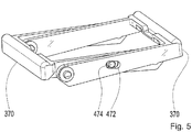
- Fig. 5 shows a perspective view of actuating means of the switching device of the radio button Fig. 3 to Fig. 4 , Shown are the actuating lever 370 and the illustration, only a slot 472 and a pin 474.
- the two operating lever 370 are shown, which are joined together to form a twin lever assembly.
- the pin 474 of a first of the actuating lever 370 in the slot 472 of a second of the actuating lever 370 is arranged.
- the pin 474 of the second of the actuating lever 370 is disposed in the slot 472 of the first of the actuating lever 370, although this is due to the presentation in Fig. 5 is not explicitly recognizable.
- Fig. 6 shows a perspective part exploded view of the wireless button 100 from Fig. 3 to Fig. 4 ,
- the radio button 100 is shown in a partially assembled state. Shown or presentation-related can be seen from the radio button 100 in Fig. 6
- FIG. 6 the operating levers 370 are joined together as shown in FIG Fig. 5 is shown and attached to the housing 110. Further, the power conversion device 150 and the auxiliary circuit board 455 are connected to each other and disposed in the housing 110. Also, the switching means, of which only the movable carriage 482 in Fig. 6 can be seen, the housing 110 is arranged. The circuit carrier 130, the switching foil 430 and the cover 310 are shown arranged in a state removed from the housing 110 or remote from the housing 110.
- Fig. 7 shows a perspective view of the energy conversion device 150 and the switching means 180 of the switching device of the radio button Fig. 3 .
- Fig. 4 and Fig. 6 Shown are in Fig. 7
- the auxiliary circuit board 455 is shown electrically and mechanically connected to the power conversion device 150. Furthermore, the energy conversion device 150 is shown mechanically coupled to the movable carriage 482.
- the switching means 180 are shown in an assembled state. Here, the carriage levers 484 are attached to opposite ends of the movable carriage 482. On each of the carriage levers 484, one of the roller 488 is mounted. Between the carriage levers 484, the tension spring 486 is tensioned. Here, the tension spring 486 extends in a cavity of the movable carriage 482. By means of the tension spring 486, the carriage lever 484 are biased into a rest position. In a switching operation, the switching means 180, in particular the movable carriage 482, between a first position and a second position relative to the energy conversion device 150 are movable or displaceable.
- Fig. 8 shows a perspective view of the circuit substrate 130 of the radio button Fig. 3 .
- Fig. 4 and Fig. 6 More specifically, in Fig. 8 in particular a main surface of the circuit carrier 130 is shown, which faces the switching foil or the cover in a state of the circuit carrier 130 mounted in the radio push-button. Shown here are from the circuit substrate 130, for example, a centrally arranged through hole 832 and only exemplary four Codierieuxe 834. Arrangement positions of the CodierBooke 834 here represent corners of an imaginary rectangle on the in Fig. 8 shown main surface of the circuit substrate 130th
- the circuit carrier 130 may be equipped with electronic components, even if this is done in FIG Fig. 8 is not recognizable due to the presentation.
- the coding contacts 834 or coding switches or contact surfaces and contacts are arranged and an antenna can be printed.
- the coding contacts 834 and their number can be freely adapted. For example, microswitches, safety mats, membrane switches, etc. may be used.
- the cover of the radio button has actuating elements for activating the coding contacts 834.
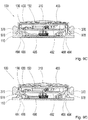
- FIGS. 9A to 9E show sectional views of the radio button 100 from Fig. 3 . Fig. 4 and Fig. 6 in different states during switching operations.
- the radio button 100 is shown in different switching phases and in an assembled or mounted state. Shown or displayed due to recognizable in the FIGS. 9A to 9E
- a bearing groove 978 is formed in each of the operation levers 370.
- Each bearing notch 978 is configured to engage a carriage lever 484.
- the radio button 100 is for the sectional views of FIGS. 9A to 9E cut along a plane that is normal with respect to a bottom plate of the housing 110 and through a longitudinal extension axis of the movable carriage 482 and the tension spring 486 extends.
- Fig. 9A in this case shows the radio button 100 in an unactuated state or idle state in the absence of an actuating force exerted on the same and thus before or after a switching operation.
- the operating lever 370 are spaced from the bottom plate of the housing 110 in its rest position.
- the switching means having the movable carriage 482, the slide levers 484, the tension spring 486 and the rollers 488 are here in the illustration of Fig. 9A from a center position to the right within the housing 110 shown offset.
- the movable carriage 482 is arranged, for example, in the first position.
- the in Fig. 9A Carriage lever 484 shown on the right is shown engaged in the bearing notch 978 of the actuating lever 370 shown on the right.
- the in Fig. 9A Slide lever 484 shown on the left is shown disengaged from the bearing notch 978 of the actuating lever 370 shown on the left.
- the carriage levers 484 are arranged in their rest position.
- Fig. 9B shows the radio button 100 in a fully actuated state with an applied actuating force during a switching operation.
- the operating lever 370 are arranged in abutment against the bottom plate of the housing 110 in a deflection position.
- the switching means are in the representation of Fig. 9B from a center position to the left shown offset within the housing 110.
- the movable carriage 482 is arranged, for example, in the second position.
- the in Fig. 9B Carriage lever 484 shown on the right is arranged in engagement with the bearing notch 978 of the actuating lever 370 shown on the right and shown in a deflection position.
- the in Fig. 9B Slide lever 484 shown on the left is shown disengaged from the bearing notch 978 of the actuating lever 370 shown on the left.
- the in Fig. 9B Slide lever 484 shown on the left is arranged in the rest position.
- Fig. 9C shows the radio button 100 in a state without applied operating force towards the end of a switching operation.
- the actuating lever 370 are arranged between its deflection position and its rest position.
- the mobile one Carriage 482 is arranged in the second position.
- the carriage levers 484 are shown disengaged from the bearing notches 978 of the actuation levers 370.
- the carriage levers 484 are arranged in their rest position.
- Fig. 9D shows the radio button 100 in an unactuated state or idle state in the absence of exerted on the same actuating force after the switching operation of FIGS. 9A to 9C ,
- the operating lever 370 are spaced from the bottom plate of the housing 110 in its rest position.
- the switching means are in the representation of Fig. 9D from a center position to the left shown offset within the housing 110.
- the movable carriage 482 is arranged in the second position.
- the in Fig. 9C Slide lever 484 shown on the left is shown engaged in the bearing notch 978 of the actuating lever 370 shown on the left.
- the in Fig. 9C The slide lever 484 shown on the right is shown disengaged from the operating lever 370 shown in the bearing notch 978 of the right.
- the carriage levers 484 are arranged in their rest position.
- Fig. 9E shows the radio button 100 in a fully actuated state at an applied operating force during another switching operation.
- the operating lever 370 are arranged in abutment against the bottom plate of the housing 110 in a deflection position.
- the switching means are in the representation of Fig. 9E from a center position to the right within the housing 110 shown offset.
- the movable carriage 482 is arranged in the first position.
- the in Fig. 9E Slide lever 484 shown on the left is arranged in engagement with the bearing notch 978 of the actuating lever 370 shown on the left and shown in a deflection position.
- the in Fig. 9E The slide lever 484 shown on the right is shown disengaged from the operating lever 370 shown in the bearing notch 978 of the right.
- the in Fig. 9E Slide lever 484 shown on the right is arranged in the rest position.
- the energy conversion device 150 is activated in one direction or the other.
- the carriage 482 is equipped from both sides with the carriage levers 484, which are optionally equipped with the rollers 488 or rollers or alternatively sliding elements for reducing frictional forces.
- the rollers 488 could be dispensed with in another embodiment.
- a slider such as a slide plate or slide block or, in general, an element with a sliding surface could be used.
- the carriage 482 would be structurally simple and thus less expensive.
- the two carriage levers 484 are connected by the tension spring 486 placed in an inner cavity of the movable carriage 482 and held in a neutral position so that they rotate clockwise and counterclockwise at least in a certain angular range , can complete.
- the tension spring force allows the carriage levers 484 to be returned to their rest position.
- the switching means or the "toggle mechanism” in an actuated state of the radio button 100 due to the bistable mechanical properties of the energy conversion device 150 in one of two positions or end positions in the housing 110, in one or the other Direction shifted.
- one of the two carriage levers 484 is arranged in an engagement position.
- an engaged carriage lever 484 Upon actuation of the actuation levers 370 and the twin lever, an engaged carriage lever 484 is entrained by a bearing notch 978 of an actuating lever and set in a rotational movement. At this time, the carriage 482 linearly moves to its second position and activates the power conversion device 150. After such switching of the power conversion device 150, the movable carriage 482 is disposed in the second position.
- the bearing notch 978 of the respective operating lever 370 is brought by means of the tension spring 486 in its neutral position or in the rest position.
- the other carriage lever 484 in the opposite direction and leaves the bearing notch 978 of the operating lever 370 pass over.
- the other carriage lever 484 is released and returns to the rest position. Now the other carriage lever 484 is in the engaged position.
- the movable carriage 482 Upon a subsequent actuation of the actuation levers 370, the movable carriage 482 is reset and activates the energy conversion device 150 again. Thus, the movable carriage 482 and the energy conversion device 150 completes a switching movement or so-called toggle movement with each further actuation.
- a button or light switch rocker is rotatably mounted on a rotation axis of the lid 110 and is in a middle position.
- a primary actuation pin of the button activates one of the actuation levers 370.
- at least one secondary actuation pin of the button activates at least one of the encoder contacts before activating the energy conversion device 150.
- an electronics of the circuit substrate 130 is supplied with energy and a correspondingly coded radio telegram or switching signal is generated in accordance with the pre-actuated coding contact.
- the at least one coding contact is switched back. The energy conversion device 150 is not activated.
- This feature can be used to generate two different switching signals when the same key is pressed.
- the switching signal is not generated immediately, but only after a time interval measurement between the closing and opening of the at least one coding contact. For example, at a time interval shorter than 100 milliseconds, a first switching signal is generated and sent. When the time interval is exceeded, a different from the first switching signal, second switching signal is sent.
- These Property can be used, for example, to distinguish between simply turning on a lamp and starting a dimming operation. For example, if you press the button briefly, the lamp will immediately turn on at full power. For example, a long press will turn the light up from dark to light. For example, pressing the button in an opposite direction produces a dimming stop signal.
- Fig. 10 shows a perspective view of a wireless button 100 according to another embodiment of the present invention.
- a housing 110 or housing base, a cover 310 or housing cover and an actuating lever 370 are shown by the radio push-button 100.
- the wireless push-button 100 corresponds to the wireless push-button Fig. 3 . Fig. 4 . Fig. 6 respectively.
- FIGS. 9A to 9E with the exception that the radio button 100 in Fig. 10 is designed as a disposable module with only one operating lever 370. The following are with reference to the FIGS. 11 to 12D Differences between the radio button 100 according to the in Fig. 10 illustrated embodiment of the present invention and the radio button Fig. 3 . Fig. 4 . Fig. 6 respectively.
- FIGS. 9A to 9E further explained.
- Fig. 11 shows an exploded perspective view of the wireless button 100 Fig. 10 ,
- the housing 110, the circuit carrier 130, the energy conversion device 150, the switching means 180, the cover 310, the actuation lever 370, the switching foil 430, the auxiliary circuit board 455, the movable carriage 482, a carriage lever 484, a roller are shown by the wireless pushbutton 100 488 and a compression spring 1186.
- Fig. 11 can be seen that in contrast to the radio button off Fig. 3 . Fig. 4 . Fig. 6 respectively.
- the radio button 100 only an actuating lever 370, which is here formed without slot and pin, only a carriage lever 484, only a roller 488 and instead of a tension spring, the compression spring 1186 has.
- the auxiliary circuit board 455 shown in a state electrically and mechanically connected to the energy conversion device 150.
- the compression spring 1186 is receivable in the movable carriage 482 and can be arranged between the carriage lever 484 and a side wall of the housing 110.
- FIGS. 9A to 9E be cheaply changed by replacing fewer parts. This eliminates the twin lever, a carriage lever, a roller, the tension spring and the return spring of the radio button Fig. 3 . Fig. 4 . Fig. 6 respectively.
- FIGS. 9A to 9E The roller 488 could be omitted as described above for cost reasons. Alternatively, instead of the roller, a sliding element according to one of the above-described embodiments could be used.
- a simple operating lever 370 is arranged, for example with a raised cam.
- the carriage lever 484 mounted on the movable carriage 482 is Fig. 3 . Fig. 4 . Fig. 6 respectively.
- FIGS. 9A to 9E extended and is continuously arranged in engagement in the bearing notch of the actuating lever 370.
- a provision of the switching means 180 by means of the compression spring 1186 which is biased in the cavity of the carriage 482 between the carriage 482 and a side wall of the housing 110.
- the energy conversion device 150 Upon actuation of the radio button 100, the energy conversion device 150 is activated and also stored a mechanical energy for a downshift in the compression spring 1186.
- the compression spring 1186 resets the switching means 180 and activates the switching back of the energy conversion device 150.
- radio button 100 can be operated with a rocker, double rocker or multiple rocker as a button. It is possible to realize a simple variant of the radio button 100 by simple conversion.
- the other processes or sequences are similar to the radio button configured as a two-way module Fig. 3 . Fig. 4 . Fig. 6 respectively.
- FIGS. 9A to 9E are similar to the radio button configured as a two-way module Fig. 3 . Fig. 4 . Fig. 6 respectively.
- FIGS. 12A to 12D show sectional views and plan views of the wireless button 100 from 10 to FIG. 11 in different states during a switching operation. Show here Fig. 12A and Fig. 12C Sectional views of the radio button 100, wherein Fig. 12B and Fig. 12D Top views of the radio button 100 show.
- FIGS. 12A and 12C Shown or due to the representation can be seen in the sectional views of FIGS. 12A and 12C in this case from the wireless pushbutton 100, the housing 110, the circuit carrier 130, the energy conversion device 150, the lid 310, the operating lever 370, the switching film 430, the auxiliary circuit board 455, the movable carriage 482, the carriage lever 484, the roller 488, a bearing notch 978 and the compression spring 1186.
- the bearing groove 978 is formed in the operation lever 370.
- the bearing notch 978 is configured to engage the carriage lever 484.
- the radio button 100 is for the sectional views of FIGS. 12A and 12C along a plane which extends normally with respect to a bottom plate of the housing 110 and through a longitudinal extension axis of the movable carriage 482 and the compression spring 1186.
- FIG. 12B and 12D Shown or due to the representation can be seen in the plan views of Figures 12B and 12D
- the wireless pushbutton 100 respectively the housing 110, the energy conversion device 150, the operating lever 370, the auxiliary circuit board 455, the movable carriage 482, the carriage lever 484 and the compression spring 1186.
- the wireless button 100 is in the plan views of Figures 12B and 12D provided without the circuit carrier, the switching device and the lid, wherein the roller and the bearing notch are hidden in the plan views.
- Fig. 12A in this case shows the radio button 100 in an unactuated state or idle state in the absence of an actuating force exerted on the same and thus before or after a switching operation.
- the operating lever 370 is spaced from a bottom plate of the housing 110 in the rest position.
- the switching means comprising the movable carriage 482, the carriage lever 484, the roller 488 and the printing errors 1186 are shown in FIG Fig. 12A from a center position to the right within the housing 110 shown offset.
- the movable carriage 482 is arranged, for example, in the first position.
- the in Fig. 12A shown slide carriage 484 is shown engaged in the bearing notch 978 of the right hand shown actuating lever 370 shown.
- the carriage lever 484 is in this case arranged in the rest position.
- the compression spring 1186 is in a relaxed state.
- Fig. 12B is a plan view of the wireless button 100 in the state Fig. 12A shown.
- Fig. 12C shows the wireless button 100 Fig. 12A in a fully actuated state with an applied actuation force during a shift.
- the operating lever 370 is arranged in abutment against the bottom plate of the housing 110 in a deflection position.
- the switching means are in the representation of Fig. 12C from a center position to the left shown offset within the housing 110.
- the movable carriage 482 is arranged, for example, in the second position.
- the carriage lever 484 is arranged in engagement with the bearing notch 978 of the operating lever 370 and in a deflection position.
- the compression spring 1186 is in a cocked or compressed state.
- Fig. 12D is a plan view of the wireless button 100 in the state Fig. 12C shown.
- a button as a rocker switch of the radio button 100 may in this case be arranged in an oblique rest position and, for example, to operate only at one point or in one direction. It may be necessary for reasons of functionality, even when releasing the button to generate an electrical energy pulse and send a second switching signal to control, for example, a dimming or a blind.
- an applied actuation force in comparison to the radio pushbutton designed as a two-way module Fig. 3 . Fig. 4 . Fig. 6 and FIGS. 9A to 9E remain essentially the same.
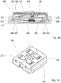
- Fig. 13 shows a perspective view of an energy conversion device and a circuit carrier of the radio button Fig. 3 . Fig. 4 . Fig. 6 and FIGS. 9A to 9E respectively.
- Fig. 10 . Fig. 11 and FIGS. 12A to 12D according to an embodiment of the present invention. Shown here are the circuit carrier 130, the energy conversion device 150, the auxiliary circuit board 455, the through hole 832 and SMD spring contacts 1336 and surface mounting contacts.
- the circuit carrier 130 in particular, a main surface is shown, which faces the energy conversion device 150 in an assembled state of the wireless pushbutton.
- the auxiliary circuit board 455 is shown electrically and mechanically connected to the power conversion device 150.
- the passage opening 832 is arranged centrally in the circuit carrier 130.
- the circuit carrier 130 is, for example, the circuit carrier Fig. 8 .
- the SMD spring contacts 1336 are disposed on the main surface of the circuit substrate 130.
- the SMD spring contacts 1336 are designed to produce an electrically conductive connection between the circuit carrier 130 and the energy conversion device 150 or to enable production thereof. Thus, an electrical contact between the circuit carrier 130 and the auxiliary circuit board 455 by means of the SMD spring contacts 1336 take place.
- Fig. 14 shows a perspective view of an energy conversion device and a circuit carrier of the radio button Fig. 3 . Fig. 4 . Fig. 6 and FIGS. 9A to 9E respectively.
- Fig. 10 . Fig. 11 and FIGS. 12A to 12D according to an embodiment of the present invention. Shown here are the circuit carrier 130, the energy conversion device 150, the through-opening 832 and punched grid spring contacts 1436.
- the circuit carrier 130 in particular a main surface is shown, which faces the energy conversion device 150 in an assembled state of the radio push button.
- the auxiliary circuit board is omitted.
- the passage opening 832 is arranged centrally in the circuit carrier 130.
- the circuit carrier 130 is, for example, the circuit carrier Fig.
- the circuit carrier 130 is in this case formed as an overmoulded stamped grid.
- the lead frame spring contacts 1436 are disposed on the main surface of the circuit substrate 130.
- the lead frame spring contacts 1436 are configured to provide an electrically conductive connection between the circuit carrier 130 and the energy conversion device 150 to produce or to enable a production thereof.
- an electrical contact between the circuit substrate 130 can be made directly with the energy conversion device 150 by means of the lead frame spring contacts 1436.
- the auxiliary circuit board and associated soldering costs can be omitted. This can bring a further cost advantage and increase the reliability of the contact.
- an exemplary embodiment comprises a "and / or" link between a first feature and a second feature
- this can be read so that the embodiment according to one embodiment, both the first feature and the second feature and according to another embodiment, either only the first Feature or only the second feature.
Landscapes
- Engineering & Computer Science (AREA)
- Power Engineering (AREA)
- Push-Button Switches (AREA)
- Switches With Compound Operations (AREA)
- Mechanisms For Operating Contacts (AREA)
Claims (9)
- Dispositif de commutation (160) d'un interrupteur sans fil (100), le dispositif de commutation (160) comportant des moyens de manoeuvre (170 ; 370 ; 472, 474, 476 ; 978) destinés à absorber une énergie mécanique pouvant être introduite dans dispositif de commutation (160), lors d'un processus de commutation, caractérisé en ce que le dispositif de commutation (160) comporte des moyens d'inversion (180 ; 482, 484, 486, 488 ; 1186) pouvant être accouplés mécaniquement avec les moyens de manoeuvre (170 ; 370 ; 472, 474, 476 ; 978) et avec un système convertisseur d'énergie (150), destiné à convertir l'énergie mécanique en une énergie électrique pour émettre un signal de commutation, pour transmettre l'énergie mécanique des moyens de manoeuvre (170 ; 370 ; 472, 474, 476 ; 978) vers le système convertisseur d'énergie (150), les moyens d'inversion (180 ; 482, 484, 486, 488 ; 1186) étant conçus pour pouvoir être manoeuvrés lors du processus de commutation par les moyens de manoeuvre (170 ; 370 ; 472, 474, 476 ; 978), pour dans un état accouplé avec le système convertisseur d'énergie (150), amener le système convertisseur d'énergie (150) d'au moins un premier état stable dans un deuxième état stable différent du premier état stable, pour générer au moins une impulsion d'énergie électrique, caractérisé en ce que les moyens d'inversion (180 ; 482, 484, 486, 488 ; 1186) comportent un chariot (482) mobile, pouvant être mécaniquement accouplé avec le système convertisseur d'énergie (150) et au moins un levier de chariot (484) susceptible d'être manoeuvré par les moyens de manoeuvre (170 ; 370 ; 472, 474, 476 ; 978), l'au moins un levier de chariot (484) étant conçu pour déplacer le chariot (482) mobile entre une première position, qui est affectée au premier état stable du système convertisseur d'énergie (150) et une deuxième position, qui est affectée au deuxième état stable du système convertisseur d'énergie (150).
- Dispositif de commutation (160) selon la revendication 1, caractérisé par au moins un galet de roulement (488) ou un élément coulissant, qui peut être accouplé mécaniquement avec le chariot (482) et/ou avec l'au moins un levier de chariot (484) .
- Dispositif de commutation (160) selon l'une quelconque des revendications 1 à 2, caractérisé en ce que les moyens d'inversion (180 ; 482, 484, 486, 488 ; 1186) comportent des moyens élastiques (1186) qui sont conçus pour agir sur le chariot (482) mobile, pour déplacer le chariot (482) de la deuxième position dans la première position.
- Dispositif de commutation (160) selon l'une quelconque des revendications 1 à 2, caractérisé en ce que les moyens d'inversion (180 ; 482, 484, 486, 488 ; 1186) comportent les moyens élastiques (486) et deux leviers de chariot (484), les moyens élastiques (486) étant conçus pour précontraindre les leviers de chariot (484) dans une position de repos, le chariot (482) mobile pouvant être placé entre les leviers de chariot (484), un premier des leviers de chariot (484) étant conçu pour déplacer le chariot (482) mobile de la première position dans la deuxième position, un deuxième des leviers de chariot (484) étant conçu pour déplacer le chariot (482) mobile de la deuxième position dans la première position.
- Interrupteur sans fil (100) comprenant un dispositif de commutation (160) selon l'une quelconque des revendications précédentes ;
un système convertisseur d'énergie (150), pouvant être couplé mécaniquement avec les moyens d'inversion (180 ; 482, 484, 486, 488 ; 1186) du dispositif de commutation (160) et qui est conçu pour convertir l'énergie mécanique pouvant être introduite dans le dispositif de commutation (160) lors du processus de commutation dans l'énergie électrique pour émettre le signal de commutation ; une plaquette de circuit (130) pourvue d'un système émetteur de signaux (140), destiné à émettre le signal de commutation, la plaquette de circuit (130) pouvant être connectée de manière à pouvoir conduire l'électricité avec le système convertisseur d'énergie (150) ;
un boîtier (110 ; 310) comportant au moins un élément de boîtier, le boîtier (110 ; 310) étant conçu pour recevoir le dispositif de commutation (160), le système convertisseur d'énergie (150) et la plaquette de circuit (130) ; et
une touche (120), destinée à transmettre l'énergie mécanique sur les moyens de manoeuvre (170 ; 370 ; 472, 474, 476 ; 978) du dispositif de commutation (160), la touche (120) pouvant être montée sur le boîtier (110 ; 310). - Interrupteur sans fil (100) selon la revendication 5, caractérisé en ce que le système émetteur de signaux (140) comporte un système radio-électronique, la carte de circuit (130) comportant au moins un contact de codage (834) qui peut être manoeuvré lors du processus de commutation, pour mettre à disposition un signal de codage.
- Interrupteur sans fil (100) selon l'une quelconque des revendications 5 à 6, caractérisé en ce que la touche (120) est façonnée comme une bascule, une double bascule ou une bascule multiple.
- Interrupteur sans fil (100) selon l'une quelconque des revendications 5 à 7, caractérisé en ce que le boîtier (110 ; 310) est façonné au moins partiellement en une matière insonorisante, pour la réduction d'un bruit de manoeuvre et/ou en ce que l'interrupteur sans fil (100) comporte une capsule insonorisante pour le système convertisseur d'énergie (150).
- Procédé (200), destiné à générer un signal de commutation d'un interrupteur sans fil (100), le procédé (200) étant réalisable en association avec un interrupteur sans fil (100) qui comporte un dispositif de commutation (160), un système convertisseur d'énergie (150), destiné à convertir de l'énergie mécanique en énergie électrique et une plaquette de circuit (130) dotée d'un système émetteur de signaux (140), la plaquette de circuit (130) étant connectée de manière conductrice d'électricité avec le système convertisseur d'énergie (150), le procédé (200) comportant les étapes suivantes, consistant à :
générer (210) au moins une impulsion d'énergie électrique, pour émettre le signal de commutation au moyen du dispositif de commutation (160) et du système convertisseur d'énergie (150), en utilisant une énergie mécanique introduite lors d'un processus de commutation dans le dispositif de commutation (160), l'énergie mécanique étant absorbée par des moyens de manoeuvre (170 ; 370 ; 472, 474, 476 ; 978) du dispositif de commutation (160) et transmise par des moyens d'inversion (180 ; 482, 484, 486, 488 ; 1186) accouplés mécaniquement avec les moyens de manoeuvre (170 ; 370 ; 472, 474, 476 ; 978) et avec le système convertisseur d'énergie (150) sur le système convertisseur d'énergie (150), lors du processus de commutation, les moyens d'inversion (180 ; 482, 484, 486, 488 ; 1186) étant manoeuvrés par les moyens de manoeuvre (170 ; 370 ; 472, 474, 476 ; 978) et pour générer l'au moins une impulsion d'énergie électrique, faire passer le système convertisseur d'énergie (150) au moins d'un premier état stable dans un deuxième état stable, différent du premier état stable, les moyens d'inversion (180 ; 482, 484, 486, 488 ; 1186) comportant un chariot (482) mobile, pouvant être accouplé mécaniquement avec le système convertisseur d'énergie (150) et au moins un levier de chariot (484) pouvant être manoeuvré à l'aide des moyens de manoeuvre (170 ; 370 ; 472, 474, 476 ; 978, l'au moins un levier de chariot (484) étant conçu pour déplacer le chariot (482) mobile entre une première position, qui est affectée au premier état stable du système convertisseur d'énergie (150) et une deuxième position, qui est affectée au deuxième état stable du système convertisseur d'énergie (150) ; et délivrer (220) par radio le signal de commutation à l'aide du système émetteur de signaux (140) en utilisant l'au moins une impulsion d'énergie électrique.
Applications Claiming Priority (2)
| Application Number | Priority Date | Filing Date | Title |
|---|---|---|---|
| DE102014209192.6A DE102014209192A1 (de) | 2014-05-15 | 2014-05-15 | Schaltvorrichtung für einen Funktaster, Funktaster und Verfahren zum Erzeugen eines Schaltsignals eines Funktasters |
| PCT/EP2015/058157 WO2015172958A1 (fr) | 2014-05-15 | 2015-04-15 | Dispositif de commutation pour interrupteur sans fil, interrupteur sans fil et procédé de génération d'un signal de commutation d'un interrupteur sans fil |
Publications (2)
| Publication Number | Publication Date |
|---|---|
| EP3143633A1 EP3143633A1 (fr) | 2017-03-22 |
| EP3143633B1 true EP3143633B1 (fr) | 2018-09-26 |
Family
ID=53008469
Family Applications (1)
| Application Number | Title | Priority Date | Filing Date |
|---|---|---|---|
| EP15718831.9A Active EP3143633B1 (fr) | 2014-05-15 | 2015-04-15 | Dispositif de commutation pour interrupteur sans fil, interrupteur sans fil et procédé de génération d'un signal de commutation d'un interrupteur sans fil |
Country Status (5)
| Country | Link |
|---|---|
| US (1) | US10373782B2 (fr) |
| EP (1) | EP3143633B1 (fr) |
| CN (1) | CN106463294B (fr) |
| DE (1) | DE102014209192A1 (fr) |
| WO (1) | WO2015172958A1 (fr) |
Families Citing this family (13)
| Publication number | Priority date | Publication date | Assignee | Title |
|---|---|---|---|---|
| CN107046783B (zh) * | 2017-01-19 | 2023-04-18 | 广东易百珑智能科技有限公司 | 防水无源无线控制器和控制系统及其应用 |
| CN112187096A (zh) * | 2017-04-01 | 2021-01-05 | 广东易百珑智能科技有限公司 | 可变更按键数目的无源回弹式开关 |
| US11742852B2 (en) * | 2017-11-28 | 2023-08-29 | YuanFang LIU | Self-powered wireless switch with micro generator and applications thereof |
| DE102017222601B4 (de) * | 2017-12-13 | 2019-08-01 | Audi Ag | Bedienelement für ein Kraftfahrzeug |
| US10915722B2 (en) | 2018-06-21 | 2021-02-09 | Datalogic Ip Tech S.R.L. | Add-on with wireless remote trigger for mobile computers |
| US10745939B2 (en) * | 2018-07-10 | 2020-08-18 | Won-Door Corporation | Wireless transmitter and related systems and methods |
| CN110266903A (zh) * | 2019-06-06 | 2019-09-20 | 广东易百珑智能科技有限公司 | 呼叫系统及其自供电发射端和呼叫方法 |
| CN110262324A (zh) * | 2019-06-06 | 2019-09-20 | 深圳市易百珑科技有限公司 | 自供电模块、无线控制开关以及无线控制系统和配对方法 |
| DE102021111403A1 (de) * | 2021-05-03 | 2022-11-03 | Schneider Electric Industries Sas | Elektrisches installationsgerät |
| TWI810592B (zh) * | 2021-06-18 | 2023-08-01 | 亞旭電腦股份有限公司 | 翹板開關及電子裝置 |
| GB202111573D0 (en) | 2021-08-12 | 2021-09-29 | Tio Point Ltd | Consumable level usage monitoring system |
| WO2025050256A1 (fr) * | 2023-09-04 | 2025-03-13 | 瑞声光电科技(常州)有限公司 | Moteur à vibration linéaire |
| WO2025076784A1 (fr) * | 2023-10-12 | 2025-04-17 | 瑞声光电科技(常州)有限公司 | Moteur à vibrations |
Family Cites Families (16)
| Publication number | Priority date | Publication date | Assignee | Title |
|---|---|---|---|---|
| GB9505045D0 (en) * | 1995-03-13 | 1995-05-03 | Ashley & Rock Ltd | Electric switch |
| US6272073B1 (en) * | 1998-11-20 | 2001-08-07 | Gary L. Doucette | Underwater location and communication device |
| US6630894B1 (en) * | 2000-07-14 | 2003-10-07 | Face International Corp. | Self-powered switching device |
| FR2815169B1 (fr) * | 2000-10-11 | 2003-08-08 | Valeo Climatisation | Dispositif de commande d'un contacteur comprenant un transmetteur, et transmetteur pour ce dispositif |
| KR100945202B1 (ko) * | 2001-07-03 | 2010-03-03 | 브래드베리 알. 페이스 | 자력발전 스위치 구동시스템 |
| DE10354043B3 (de) * | 2003-11-19 | 2005-06-16 | Electrolux Home Products Corp. N.V. | Tastenblock zum Einsetzen in eine Bedienfläche eines Haushaltgeräts |
| DE202004005837U1 (de) | 2004-04-14 | 2004-07-08 | Enocean Gmbh | Schaltergehäuse zur Aufputzmontage und zur Aufnahme eines elektronischen Moduls |
| UA87116C2 (en) * | 2006-05-19 | 2009-06-25 | Кулигин Виктор Иванович | Electrodynamical drive |
| DE102010003152A1 (de) | 2010-03-23 | 2011-09-29 | Zf Friedrichshafen Ag | Funkschalter |
| DE102010028623A1 (de) * | 2010-05-05 | 2011-11-10 | Zf Friedrichshafen Ag | Induktionsgenerator |
| DE102011076191A1 (de) * | 2011-05-20 | 2012-11-22 | Siemens Aktiengesellschaft | Energiewandler, Funktaster mit einem Energiewandler sowie Anordnung zum Stellen zumindest einer elektrisch ortsgestellten Weiche eines schienengebundenden Verkehrsweges mit zumindest einem Funktaster |
| DE102011084407A1 (de) | 2011-10-13 | 2013-04-18 | Zf Friedrichshafen Ag | Schaltmodul für einen Schalter, Schalter, Verfahren zum Anzeigen einer Betätigung eines Schalters und Verfahren zum Steuern einer Vorrichtung |
| WO2013093715A1 (fr) * | 2011-12-20 | 2013-06-27 | Koninklijke Philips Electronics N.V. | Commutateur de collecte d'énergie autoalimenté et procédé de collecte d'énergie |
| DE202012008994U1 (de) * | 2012-09-19 | 2014-01-09 | Grass Gmbh | Möbel und Vorrichtung zur Bewegungskontrolle eines Möbelteils |
| ITTO20120833A1 (it) * | 2012-09-26 | 2014-03-27 | St Microelectronics Srl | Dispositivo contapassi dotato di funzionalita' di raccolta di energia e metodo di conteggio dei passi |
| DE102012112897A1 (de) | 2012-12-21 | 2014-07-10 | Eltako GmbH Schaltgeräte | Funkschalter |
-
2014
- 2014-05-15 DE DE102014209192.6A patent/DE102014209192A1/de not_active Withdrawn
-
2015
- 2015-04-15 WO PCT/EP2015/058157 patent/WO2015172958A1/fr not_active Ceased
- 2015-04-15 CN CN201580024123.1A patent/CN106463294B/zh active Active
- 2015-04-15 EP EP15718831.9A patent/EP3143633B1/fr active Active
- 2015-04-15 US US15/310,992 patent/US10373782B2/en active Active
Non-Patent Citations (1)
| Title |
|---|
| None * |
Also Published As
| Publication number | Publication date |
|---|---|
| EP3143633A1 (fr) | 2017-03-22 |
| US10373782B2 (en) | 2019-08-06 |
| CN106463294A (zh) | 2017-02-22 |
| US20170076888A1 (en) | 2017-03-16 |
| CN106463294B (zh) | 2018-10-26 |
| DE102014209192A1 (de) | 2015-11-19 |
| WO2015172958A1 (fr) | 2015-11-19 |
Similar Documents
| Publication | Publication Date | Title |
|---|---|---|
| EP3143633A1 (fr) | Dispositif de commutation pour interrupteur sans fil, interrupteur sans fil et procédé de génération d'un signal de commutation d'un interrupteur sans fil | |
| EP3008742B1 (fr) | Dispositif de commutation pour un bouton-poussoir émetteur, bouton-poussoir émetteur, et procédé de génération d'un signal de commutation d'un dispositif de commutation | |
| EP2766913B1 (fr) | Module de commutation pour commutateur, commutateur, procédé permettant d'afficher un actionnement d'un commutateur et procédé permettant de commander un dispositif | |
| DE19537296C2 (de) | Wippenschaltvorrichtung für zweistufigen Betätigungshub | |
| EP1550202B1 (fr) | Commutateur radio electromecanique a autonomie energetique | |
| EP2941779B1 (fr) | Ensemble touche et élément emboîtable pour ensemble touche | |
| DE19853438A1 (de) | Multidirektionale Tastschalteranordnung | |
| DE2918640A1 (de) | Druckknopfschalter | |
| DE10033452A1 (de) | Tableaueingabevorrichtung mit Schalter | |
| DE3613702C2 (fr) | ||
| DE19634051C1 (de) | Schalteranordnung mit mindestens einer Drucktaste | |
| EP3939062B1 (fr) | Dispositif d'installation électrique | |
| DE602004002626T2 (de) | Schalteranordnung | |
| EP0017820B1 (fr) | Dispositif de prolongement pour mécanismes de commande à bouton-poussoir | |
| EP0817446A2 (fr) | Dispositif de commutation pour postes téléphoniques | |
| DE102005013522A1 (de) | Multifunktionelle Schalteranordnung | |
| DE10319180B4 (de) | Elektrische Einstellvorrichtung | |
| DE2741219A1 (de) | Schaltervorrichtung | |
| EP1485929B1 (fr) | Element de reglage a base d'un interrupteur a membrane | |
| EP1501108B1 (fr) | Interrupteur multidirectionnel | |
| EP1355332B1 (fr) | Appareil de contact électrique et clavier correspondant | |
| DE102010019117A1 (de) | Elektromotorischer Möbelantrieb zum Verstellen von Teilen eines Möbels relativ zueinander | |
| EP4645361A1 (fr) | Appareil de commutation électrique/électronique, réseau et ensemble | |
| DE4137890A1 (de) | Elektrische schalteranordnung | |
| DE3114563A1 (de) | Drucktastenschalter |
Legal Events
| Date | Code | Title | Description |
|---|---|---|---|
| STAA | Information on the status of an ep patent application or granted ep patent |
Free format text: STATUS: THE INTERNATIONAL PUBLICATION HAS BEEN MADE |
|
| PUAI | Public reference made under article 153(3) epc to a published international application that has entered the european phase |
Free format text: ORIGINAL CODE: 0009012 |
|
| STAA | Information on the status of an ep patent application or granted ep patent |
Free format text: STATUS: REQUEST FOR EXAMINATION WAS MADE |
|
| 17P | Request for examination filed |
Effective date: 20161013 |
|
| AK | Designated contracting states |
Kind code of ref document: A1 Designated state(s): AL AT BE BG CH CY CZ DE DK EE ES FI FR GB GR HR HU IE IS IT LI LT LU LV MC MK MT NL NO PL PT RO RS SE SI SK SM TR |
|
| AX | Request for extension of the european patent |
Extension state: BA ME |
|
| DAV | Request for validation of the european patent (deleted) | ||
| DAX | Request for extension of the european patent (deleted) | ||
| GRAP | Despatch of communication of intention to grant a patent |
Free format text: ORIGINAL CODE: EPIDOSNIGR1 |
|
| STAA | Information on the status of an ep patent application or granted ep patent |
Free format text: STATUS: GRANT OF PATENT IS INTENDED |
|
| INTG | Intention to grant announced |
Effective date: 20180507 |
|
| GRAS | Grant fee paid |
Free format text: ORIGINAL CODE: EPIDOSNIGR3 |
|
| GRAA | (expected) grant |
Free format text: ORIGINAL CODE: 0009210 |
|
| STAA | Information on the status of an ep patent application or granted ep patent |
Free format text: STATUS: THE PATENT HAS BEEN GRANTED |
|
| AK | Designated contracting states |
Kind code of ref document: B1 Designated state(s): AL AT BE BG CH CY CZ DE DK EE ES FI FR GB GR HR HU IE IS IT LI LT LU LV MC MK MT NL NO PL PT RO RS SE SI SK SM TR |
|
| REG | Reference to a national code |
Ref country code: GB Ref legal event code: FG4D Free format text: NOT ENGLISH |
|
| REG | Reference to a national code |
Ref country code: CH Ref legal event code: EP |
|
| REG | Reference to a national code |
Ref country code: AT Ref legal event code: REF Ref document number: 1047002 Country of ref document: AT Kind code of ref document: T Effective date: 20181015 |
|
| REG | Reference to a national code |
Ref country code: IE Ref legal event code: FG4D Free format text: LANGUAGE OF EP DOCUMENT: GERMAN |
|
| REG | Reference to a national code |
Ref country code: DE Ref legal event code: R096 Ref document number: 502015006089 Country of ref document: DE |
|
| REG | Reference to a national code |
Ref country code: NL Ref legal event code: MP Effective date: 20180926 |
|
| PG25 | Lapsed in a contracting state [announced via postgrant information from national office to epo] |
Ref country code: NO Free format text: LAPSE BECAUSE OF FAILURE TO SUBMIT A TRANSLATION OF THE DESCRIPTION OR TO PAY THE FEE WITHIN THE PRESCRIBED TIME-LIMIT Effective date: 20181226 Ref country code: GR Free format text: LAPSE BECAUSE OF FAILURE TO SUBMIT A TRANSLATION OF THE DESCRIPTION OR TO PAY THE FEE WITHIN THE PRESCRIBED TIME-LIMIT Effective date: 20181227 Ref country code: LT Free format text: LAPSE BECAUSE OF FAILURE TO SUBMIT A TRANSLATION OF THE DESCRIPTION OR TO PAY THE FEE WITHIN THE PRESCRIBED TIME-LIMIT Effective date: 20180926 Ref country code: BG Free format text: LAPSE BECAUSE OF FAILURE TO SUBMIT A TRANSLATION OF THE DESCRIPTION OR TO PAY THE FEE WITHIN THE PRESCRIBED TIME-LIMIT Effective date: 20181226 Ref country code: FI Free format text: LAPSE BECAUSE OF FAILURE TO SUBMIT A TRANSLATION OF THE DESCRIPTION OR TO PAY THE FEE WITHIN THE PRESCRIBED TIME-LIMIT Effective date: 20180926 Ref country code: RS Free format text: LAPSE BECAUSE OF FAILURE TO SUBMIT A TRANSLATION OF THE DESCRIPTION OR TO PAY THE FEE WITHIN THE PRESCRIBED TIME-LIMIT Effective date: 20180926 Ref country code: SE Free format text: LAPSE BECAUSE OF FAILURE TO SUBMIT A TRANSLATION OF THE DESCRIPTION OR TO PAY THE FEE WITHIN THE PRESCRIBED TIME-LIMIT Effective date: 20180926 |
|
| REG | Reference to a national code |
Ref country code: LT Ref legal event code: MG4D |
|
| PG25 | Lapsed in a contracting state [announced via postgrant information from national office to epo] |
Ref country code: LV Free format text: LAPSE BECAUSE OF FAILURE TO SUBMIT A TRANSLATION OF THE DESCRIPTION OR TO PAY THE FEE WITHIN THE PRESCRIBED TIME-LIMIT Effective date: 20180926 Ref country code: AL Free format text: LAPSE BECAUSE OF FAILURE TO SUBMIT A TRANSLATION OF THE DESCRIPTION OR TO PAY THE FEE WITHIN THE PRESCRIBED TIME-LIMIT Effective date: 20180926 Ref country code: HR Free format text: LAPSE BECAUSE OF FAILURE TO SUBMIT A TRANSLATION OF THE DESCRIPTION OR TO PAY THE FEE WITHIN THE PRESCRIBED TIME-LIMIT Effective date: 20180926 |
|
| PG25 | Lapsed in a contracting state [announced via postgrant information from national office to epo] |
Ref country code: EE Free format text: LAPSE BECAUSE OF FAILURE TO SUBMIT A TRANSLATION OF THE DESCRIPTION OR TO PAY THE FEE WITHIN THE PRESCRIBED TIME-LIMIT Effective date: 20180926 Ref country code: PL Free format text: LAPSE BECAUSE OF FAILURE TO SUBMIT A TRANSLATION OF THE DESCRIPTION OR TO PAY THE FEE WITHIN THE PRESCRIBED TIME-LIMIT Effective date: 20180926 Ref country code: ES Free format text: LAPSE BECAUSE OF FAILURE TO SUBMIT A TRANSLATION OF THE DESCRIPTION OR TO PAY THE FEE WITHIN THE PRESCRIBED TIME-LIMIT Effective date: 20180926 Ref country code: IS Free format text: LAPSE BECAUSE OF FAILURE TO SUBMIT A TRANSLATION OF THE DESCRIPTION OR TO PAY THE FEE WITHIN THE PRESCRIBED TIME-LIMIT Effective date: 20190126 Ref country code: NL Free format text: LAPSE BECAUSE OF FAILURE TO SUBMIT A TRANSLATION OF THE DESCRIPTION OR TO PAY THE FEE WITHIN THE PRESCRIBED TIME-LIMIT Effective date: 20180926 Ref country code: RO Free format text: LAPSE BECAUSE OF FAILURE TO SUBMIT A TRANSLATION OF THE DESCRIPTION OR TO PAY THE FEE WITHIN THE PRESCRIBED TIME-LIMIT Effective date: 20180926 Ref country code: CZ Free format text: LAPSE BECAUSE OF FAILURE TO SUBMIT A TRANSLATION OF THE DESCRIPTION OR TO PAY THE FEE WITHIN THE PRESCRIBED TIME-LIMIT Effective date: 20180926 |
|
| PG25 | Lapsed in a contracting state [announced via postgrant information from national office to epo] |
Ref country code: SM Free format text: LAPSE BECAUSE OF FAILURE TO SUBMIT A TRANSLATION OF THE DESCRIPTION OR TO PAY THE FEE WITHIN THE PRESCRIBED TIME-LIMIT Effective date: 20180926 Ref country code: PT Free format text: LAPSE BECAUSE OF FAILURE TO SUBMIT A TRANSLATION OF THE DESCRIPTION OR TO PAY THE FEE WITHIN THE PRESCRIBED TIME-LIMIT Effective date: 20190126 Ref country code: SK Free format text: LAPSE BECAUSE OF FAILURE TO SUBMIT A TRANSLATION OF THE DESCRIPTION OR TO PAY THE FEE WITHIN THE PRESCRIBED TIME-LIMIT Effective date: 20180926 |
|
| REG | Reference to a national code |
Ref country code: DE Ref legal event code: R097 Ref document number: 502015006089 Country of ref document: DE |
|
| PG25 | Lapsed in a contracting state [announced via postgrant information from national office to epo] |
Ref country code: DK Free format text: LAPSE BECAUSE OF FAILURE TO SUBMIT A TRANSLATION OF THE DESCRIPTION OR TO PAY THE FEE WITHIN THE PRESCRIBED TIME-LIMIT Effective date: 20180926 |
|
| PLBE | No opposition filed within time limit |
Free format text: ORIGINAL CODE: 0009261 |
|
| STAA | Information on the status of an ep patent application or granted ep patent |
Free format text: STATUS: NO OPPOSITION FILED WITHIN TIME LIMIT |
|
| 26N | No opposition filed |
Effective date: 20190627 |
|
| PG25 | Lapsed in a contracting state [announced via postgrant information from national office to epo] |
Ref country code: SI Free format text: LAPSE BECAUSE OF FAILURE TO SUBMIT A TRANSLATION OF THE DESCRIPTION OR TO PAY THE FEE WITHIN THE PRESCRIBED TIME-LIMIT Effective date: 20180926 |
|
| REG | Reference to a national code |
Ref country code: CH Ref legal event code: PL |
|
| REG | Reference to a national code |
Ref country code: BE Ref legal event code: MM Effective date: 20190430 |
|
| GBPC | Gb: european patent ceased through non-payment of renewal fee |
Effective date: 20190415 |
|
| PG25 | Lapsed in a contracting state [announced via postgrant information from national office to epo] |
Ref country code: MC Free format text: LAPSE BECAUSE OF FAILURE TO SUBMIT A TRANSLATION OF THE DESCRIPTION OR TO PAY THE FEE WITHIN THE PRESCRIBED TIME-LIMIT Effective date: 20180926 Ref country code: LU Free format text: LAPSE BECAUSE OF NON-PAYMENT OF DUE FEES Effective date: 20190415 |
|
| PG25 | Lapsed in a contracting state [announced via postgrant information from national office to epo] |
Ref country code: LI Free format text: LAPSE BECAUSE OF NON-PAYMENT OF DUE FEES Effective date: 20190430 Ref country code: CH Free format text: LAPSE BECAUSE OF NON-PAYMENT OF DUE FEES Effective date: 20190430 Ref country code: GB Free format text: LAPSE BECAUSE OF NON-PAYMENT OF DUE FEES Effective date: 20190415 |
|
| PG25 | Lapsed in a contracting state [announced via postgrant information from national office to epo] |
Ref country code: BE Free format text: LAPSE BECAUSE OF NON-PAYMENT OF DUE FEES Effective date: 20190430 |
|
| PG25 | Lapsed in a contracting state [announced via postgrant information from national office to epo] |
Ref country code: TR Free format text: LAPSE BECAUSE OF FAILURE TO SUBMIT A TRANSLATION OF THE DESCRIPTION OR TO PAY THE FEE WITHIN THE PRESCRIBED TIME-LIMIT Effective date: 20180926 |
|
| PG25 | Lapsed in a contracting state [announced via postgrant information from national office to epo] |
Ref country code: IE Free format text: LAPSE BECAUSE OF NON-PAYMENT OF DUE FEES Effective date: 20190415 |
|
| PGFP | Annual fee paid to national office [announced via postgrant information from national office to epo] |
Ref country code: IT Payment date: 20210310 Year of fee payment: 7 |
|
| PG25 | Lapsed in a contracting state [announced via postgrant information from national office to epo] |
Ref country code: CY Free format text: LAPSE BECAUSE OF FAILURE TO SUBMIT A TRANSLATION OF THE DESCRIPTION OR TO PAY THE FEE WITHIN THE PRESCRIBED TIME-LIMIT Effective date: 20180926 |
|
| REG | Reference to a national code |
Ref country code: AT Ref legal event code: MM01 Ref document number: 1047002 Country of ref document: AT Kind code of ref document: T Effective date: 20200415 |
|
| PG25 | Lapsed in a contracting state [announced via postgrant information from national office to epo] |
Ref country code: HU Free format text: LAPSE BECAUSE OF FAILURE TO SUBMIT A TRANSLATION OF THE DESCRIPTION OR TO PAY THE FEE WITHIN THE PRESCRIBED TIME-LIMIT; INVALID AB INITIO Effective date: 20150415 Ref country code: MT Free format text: LAPSE BECAUSE OF FAILURE TO SUBMIT A TRANSLATION OF THE DESCRIPTION OR TO PAY THE FEE WITHIN THE PRESCRIBED TIME-LIMIT Effective date: 20180926 |
|
| PG25 | Lapsed in a contracting state [announced via postgrant information from national office to epo] |
Ref country code: AT Free format text: LAPSE BECAUSE OF NON-PAYMENT OF DUE FEES Effective date: 20200415 |
|
| PG25 | Lapsed in a contracting state [announced via postgrant information from national office to epo] |
Ref country code: MK Free format text: LAPSE BECAUSE OF FAILURE TO SUBMIT A TRANSLATION OF THE DESCRIPTION OR TO PAY THE FEE WITHIN THE PRESCRIBED TIME-LIMIT Effective date: 20180926 |
|
| PG25 | Lapsed in a contracting state [announced via postgrant information from national office to epo] |
Ref country code: IT Free format text: LAPSE BECAUSE OF NON-PAYMENT OF DUE FEES Effective date: 20220415 |
|
| P01 | Opt-out of the competence of the unified patent court (upc) registered |
Effective date: 20230528 |
|
| PGFP | Annual fee paid to national office [announced via postgrant information from national office to epo] |
Ref country code: DE Payment date: 20250305 Year of fee payment: 11 |
|
| PGFP | Annual fee paid to national office [announced via postgrant information from national office to epo] |
Ref country code: FR Payment date: 20260309 Year of fee payment: 12 |