EP3143637B1 - Dispositif de commutation d'un circuit électrique principal - Google Patents
Dispositif de commutation d'un circuit électrique principal Download PDFInfo
- Publication number
- EP3143637B1 EP3143637B1 EP15737961.1A EP15737961A EP3143637B1 EP 3143637 B1 EP3143637 B1 EP 3143637B1 EP 15737961 A EP15737961 A EP 15737961A EP 3143637 B1 EP3143637 B1 EP 3143637B1
- Authority
- EP
- European Patent Office
- Prior art keywords
- switch
- control unit
- control
- voltage
- sensor
- Prior art date
- Legal status (The legal status is an assumption and is not a legal conclusion. Google has not performed a legal analysis and makes no representation as to the accuracy of the status listed.)
- Active
Links
Images
Classifications
-
- H—ELECTRICITY
- H01—ELECTRIC ELEMENTS
- H01H—ELECTRIC SWITCHES; RELAYS; SELECTORS; EMERGENCY PROTECTIVE DEVICES
- H01H47/00—Circuit arrangements not adapted to a particular application of the relay and designed to obtain desired operating characteristics or to provide energising current
- H01H47/22—Circuit arrangements not adapted to a particular application of the relay and designed to obtain desired operating characteristics or to provide energising current for supplying energising current for relay coil
- H01H47/32—Energising current supplied by semiconductor device
-
- F—MECHANICAL ENGINEERING; LIGHTING; HEATING; WEAPONS; BLASTING
- F04—POSITIVE - DISPLACEMENT MACHINES FOR LIQUIDS; PUMPS FOR LIQUIDS OR ELASTIC FLUIDS
- F04D—NON-POSITIVE-DISPLACEMENT PUMPS
- F04D15/00—Control, e.g. regulation, of pumps, pumping installations or systems
- F04D15/02—Stopping of pumps, or operating valves, on occurrence of unwanted conditions
- F04D15/0209—Stopping of pumps, or operating valves, on occurrence of unwanted conditions responsive to a condition of the working fluid
- F04D15/0218—Stopping of pumps, or operating valves, on occurrence of unwanted conditions responsive to a condition of the working fluid the condition being a liquid level or a lack of liquid supply
- F04D15/0227—Lack of liquid level being detected using a flow transducer
-
- H—ELECTRICITY
- H02—GENERATION; CONVERSION OR DISTRIBUTION OF ELECTRIC POWER
- H02J—ELECTRIC POWER NETWORKS; CIRCUIT ARRANGEMENTS OR SYSTEMS FOR SUPPLYING OR DISTRIBUTING ELECTRIC POWER; SYSTEMS FOR STORING ELECTRIC ENERGY
- H02J9/00—Circuit arrangements for emergency or stand-by power supply, e.g. for emergency lighting
- H02J9/005—Circuit arrangements for emergency or stand-by power supply, e.g. for emergency lighting using a power saving mode
-
- H—ELECTRICITY
- H01—ELECTRIC ELEMENTS
- H01H—ELECTRIC SWITCHES; RELAYS; SELECTORS; EMERGENCY PROTECTIVE DEVICES
- H01H2300/00—Orthogonal indexing scheme relating to electric switches, relays, selectors or emergency protective devices covered by H01H
- H01H2300/022—Application wake up; switches or contacts specially provided for the wake up or standby shift of a circuit
-
- H—ELECTRICITY
- H01—ELECTRIC ELEMENTS
- H01H—ELECTRIC SWITCHES; RELAYS; SELECTORS; EMERGENCY PROTECTIVE DEVICES
- H01H9/00—Details of switching devices, not covered by groups H01H1/00 - H01H7/00
- H01H9/54—Circuit arrangements not adapted to a particular application of the switching device and for which no provision exists elsewhere
- H01H9/547—Combinations of mechanical switches and static switches, the latter being controlled by the former
-
- H—ELECTRICITY
- H02—GENERATION; CONVERSION OR DISTRIBUTION OF ELECTRIC POWER
- H02J—ELECTRIC POWER NETWORKS; CIRCUIT ARRANGEMENTS OR SYSTEMS FOR SUPPLYING OR DISTRIBUTING ELECTRIC POWER; SYSTEMS FOR STORING ELECTRIC ENERGY
- H02J9/00—Circuit arrangements for emergency or stand-by power supply, e.g. for emergency lighting
- H02J9/005—Circuit arrangements for emergency or stand-by power supply, e.g. for emergency lighting using a power saving mode
- H02J9/007—Detection of the absence of a load
-
- Y—GENERAL TAGGING OF NEW TECHNOLOGICAL DEVELOPMENTS; GENERAL TAGGING OF CROSS-SECTIONAL TECHNOLOGIES SPANNING OVER SEVERAL SECTIONS OF THE IPC; TECHNICAL SUBJECTS COVERED BY FORMER USPC CROSS-REFERENCE ART COLLECTIONS [XRACs] AND DIGESTS
- Y02—TECHNOLOGIES OR APPLICATIONS FOR MITIGATION OR ADAPTATION AGAINST CLIMATE CHANGE
- Y02B—CLIMATE CHANGE MITIGATION TECHNOLOGIES RELATED TO BUILDINGS, e.g. HOUSING, HOUSE APPLIANCES OR RELATED END-USER APPLICATIONS
- Y02B70/00—Technologies for an efficient end-user side electric power management and consumption
- Y02B70/30—Systems integrating technologies related to power network operation and communication or information technologies for improving the carbon footprint of the management of residential or tertiary loads, i.e. smart grids as climate change mitigation technology in the buildings sector, including also the last stages of power distribution and the control, monitoring or operating management systems at local level
-
- Y—GENERAL TAGGING OF NEW TECHNOLOGICAL DEVELOPMENTS; GENERAL TAGGING OF CROSS-SECTIONAL TECHNOLOGIES SPANNING OVER SEVERAL SECTIONS OF THE IPC; TECHNICAL SUBJECTS COVERED BY FORMER USPC CROSS-REFERENCE ART COLLECTIONS [XRACs] AND DIGESTS
- Y04—INFORMATION OR COMMUNICATION TECHNOLOGIES HAVING AN IMPACT ON OTHER TECHNOLOGY AREAS
- Y04S—SYSTEMS INTEGRATING TECHNOLOGIES RELATED TO POWER NETWORK OPERATION, COMMUNICATION OR INFORMATION TECHNOLOGIES FOR IMPROVING THE ELECTRICAL POWER GENERATION, TRANSMISSION, DISTRIBUTION, MANAGEMENT OR USAGE, i.e. SMART GRIDS
- Y04S20/00—Management or operation of end-user stationary applications or the last stages of power distribution; Controlling, monitoring or operating thereof
- Y04S20/20—End-user application control systems
Definitions
- the invention relates to a device for switching a main circuit for power supply to a power consumer with a main switch in the main circuit, a control for actuating the main switch, which evaluates one or more control signals for this purpose, a power supply that can be connected to a voltage source and serves to supply power to the control , and with a sensor, the condition of which influences the actuation of the main switch.
- Such a device is used for. B. used for the power supply of a submersible pump, as in the DE 20 2013 000 051 U1 is described.
- a pressure-actuated switch located in the main circuit, as a result of which the submersible pump is started, which then pumps water into the water pipe.
- a reed contact is closed, which is parallel to the aforementioned switch, whereby the power supply of the submersible pump is maintained as long as water is still taken from the water pipe.
- the power consumption of pump motors is relatively high, so that it could be determined that conventional reed contacts tend to cake due to the high currents, i.e. they no longer open when the magnet actuating them is removed by an interruption in the water flow.
- the reed contact should not be switched directly into the main power line for the power supply of the water pump, but rather there should be a relay (main switch) which is actuated by a control.
- the flow through the water pipe is still monitored using a reed contact.
- the controller evaluates the state of the reed contact (open, closed). If it is closed due to a water flow, a corresponding signal is given to actuate the relay in the main power line.
- This relay is designed so that it can withstand the currents occurring in the main circuit without damage.
- Such a control for supplying a liquid feed pump, which feeds water into a carbonator, is in the DE 90 17 846 described.
- Controls of this type have the disadvantage, however, that they have a high stand-by consumption, since a constant check of the reed contact or another flow sensor is necessary.
- EP 1 783 887 A1 describes a circuit for actuating the main switch of a device in which the control is connected via a power supply switch either to a battery or to a supply output of the device to be switched.
- the control system also receives a signal from a switch-on circuit, on the basis of which the main switch is operated or the Switching to a stand-by mode in which only the switch-on circuit is still supplied with power, which reduces the power consumption in stand-by mode but does not completely reduce it to zero.
- the invention is therefore based on the object, in a device as defined in the preamble of claim 1, in which the operation of the consumer is controlled by the state of a sensor, in such a way that the power consumption in stand-by mode increases zero without manual operation.
- the power supply unit can be connected to the voltage source using a sub-switch, that the state of the sensor influences the switching state of the sub-switch and that the control is set up in such a way that a state of the device, according to which the control is powered off is supplied to the switched-on power supply, serves as a control signal that uses the control to actuate the main switch.
- the sensor therefore fulfills two tasks: Firstly, when it is actuated, the power pack is connected to a voltage source and thus the control of the main switch is supplied with current. On the other hand, a logic signal is made available on the basis of the power supply, which the controller uses to actuate the main switch.
- the senor When controlling a water pump, the sensor is e.g. B. - as already described above - a reed contact that registers the water flow in a water supply fed by the water pump. If the water pipe is opened by activating a tap, the reed contact is closed by the water flow. This causes both the power supply for the control of the main switch to be activated and the main switch to be closed as a result, so that pump delivery begins, which lasts at least as long as water flows through the water pipe and the water flow does not by closing the tap is interrupted again.
- Such a circuit has no power consumption in stand-by mode, that is to say when the water pump is not running, since the control is separated from the voltage source supplying it with power.
- the controller has a logic circuit which has a control input which is connected to a pole of the power supply unit, so that the voltage applied there is supplied to the logic circuit as a control signal .
- the consumer it may be necessary to operate the consumer, at least for a short time, even when the sensor is no longer providing a signal.
- This is e.g. B. the case of a pump control when the water line is closed again. With the water pump running on, the aim is to build up a pressure in the water line that is closed again, so that when the water line is opened again, an initial water flow occurs, which causes the water pump to be switched on, as described above.
- the invention provides that the control has a stop output which is connected to the secondary switch in such a way that the secondary switch is actuated when a stop signal is output at the stop output.
- the controller can be set up in such a way that the stop signal is time-controlled. This allows the run-on time of the water pump and thus the pressure build-up in the closed water pipe to be set.
- the control system Since the power supply to the control system is interrupted when the flow is ended, it is provided that the control system has a short-term current memory, which allows a stop signal to be output even if the power supply to the control system has been interrupted by the power supply unit. In this way, the Water pump can be kept in operation. The brief interruption of the power supply continues to serve as a trigger signal for the start of the run-on time.
- the proposed circuit ensures that the standby power consumption is zero.
- the power supply unit consists of a buck converter and a rectifier connected in front of it, the secondary switch being connected between the buck converter and the rectifier.
- Such a buck converter is known to have very low consumption.
- the rectifier continues to provide the voltage required to operate the auxiliary switch.
- the secondary switch is preferably designed as a voltage-controlled electronic switch.
- Voltage-controlled means that only the application of a voltage, but not the flow of a current, leads to the actuation of the switch.
- the secondary switch is designed as a voltage-controlled electronic switch, that the sensor has a closable contact, which is connected in series with a series resistor to the output of the rectifier, and that a branch between the series resistor and the sensor is connected to the control input of the electronic switch.
- the closable contact can e.g. B. be a reed contact.
- the electronic switch is preferably a field effect transistor or a C-MOS.
- the closable contact As soon as the closable contact (reed contact) is closed, it forms, together with the series resistor, a kind of voltage divider, the center tap of which provides a voltage at the voltage-controlled electronic switch.
- the voltage for the voltage-controlled auxiliary switch can also be provided in other ways.
- the sensor may be a capacitor connected to an antenna so that it can be charged due to electromagnetic radiation. This can be high-frequency radiation, but also infrared radiation.
- the capacitor is connected to the control input of the electronic switch. Since this only requires a voltage, but hardly any current for switching, sufficient energy for charging the capacitor can easily be used e.g. B. derived from a weak radio signal.
- the voltage for the voltage-controlled auxiliary switch can also be generated by a sound transducer, such as. B. a piezo element.
- the senor being installed in such a way that it senses the water flow through a water line fed by the water pump.
- the voltage source is a DC voltage source
- the secondary switch is designed as a voltage-controlled electronic switch. Because then it only needs to be provided with an electrical voltage to switch without the switching process requiring electrical energy. With this measure alone it is achieved that the standby consumption becomes zero, without it having to be provided that the mains voltage present at the control system would have to be evaluated as a control signal.
- the power supply unit preferably consists of a buck converter and a rectifier connected in front of it, the secondary switch being arranged between the buck converter and the rectifier.
- one pole of the power supply unit is connected to a control input of the logic circuit of the controller.
- a control stop output can also be implemented.
- the invention also relates to a water pump which is driven by a motor connected to a main circuit and on the pressure side of which a water pipe is connected which ends in a water withdrawal point, a sensor being installed on the water pipe and being sensitive to a water flow through the water pipe appeals.
- the sensor is embedded in a device for switching the main circuit, as described above.
- control forms a control signal, which must be present in any case so that the motor of the water pump can be switched on.
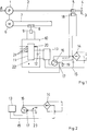
- Fig. 1 The invention is described on the basis of a pump control for a water supply system.
- This consists of a water pump 1, which conveys water from a water network or a water reservoir into a water pipe 2 to a tapping point 3.
- the tapping point 3 is provided with a tap that can be opened or closed manually.
- a water monitor 5 which is generally used to detect the flow through a water pipe.
- a typical design of a water monitor 5 has a membrane equipped with a magnet which bends due to a pressure reduction caused by the flowing water, as a result of which the magnet is moved towards a reed contact 18 and closes it.
- the water pump 1 is driven by an electric motor 6, which is connected to a voltage source via a main circuit 7.
- a main switch 8 which is actuated electromagnetically by an electromagnet 9.
- an electronic control 10 with a logic circuit 11 is provided.
- an electrical short-term current storage device in the form of a capacitor 12 is located at the input for the power supply to the controller 10.
- the control 10 is supplied with electrical energy by means of a power supply unit 13 which is connected to a rectifier 14, a voltage-controlled electronic switch in the form of a field-effect transistor 16 being connected in the supply circuit 15 between the rectifier 14 and the power supply unit 13 and acting as a secondary switch acts in the sense of the invention.
- the gate 17 of the field effect transistor 16 is connected to the center tap of a voltage divider, which consists of the above-mentioned reed contact 18 on the flow switch 5 and a series resistor 19.
- the series resistor 19 In order to load the rectifier 14 as little as possible, the series resistor 19 has a high resistance.
- a field effect transistor 16 only requires a switching voltage at its gate for switching. When switching, there is no energy consumption by the gate, so that the field effect transistor 16 can be switched without loss.
- the power supply to the controller 10 also serves to provide the actuating current for the electromagnet 9.
- the controller 10 contains a logic circuit 11, to which the voltage output by the power supply unit 13 is applied as a control signal via a first control line 20.
- This control signal is possibly required together with further signals at the further control inputs 21 in order to determine whether the electromagnet 9 can be supplied with current for closing the main switch 8.
- the reed contact 18 is opened, so that the gate 17 is de-energized and the field effect transistor 16 blocks.
- the power supply to the power supply unit 13 and consequently also the power supply to the controller 10 are thus interrupted.
- the main switch 8 also opens.
- the logic circuit 11 provides a holding output 22 which is connected to the gate 17.
- the holding output 22 is connected to a time circuit, not shown here, so that even after the water line 2 is closed, the field effect transistor 16 remains switched on due to the voltage signal from the holding output 22, so that the controller 10 continues to keep the main switch 8 closed.
- the drop in the voltage at the first control input 20 is first registered, as a result of which a timer is put into operation and a holding voltage is output at the holding output 22. Since there is no power supply for the controller 10 at this moment, the power supply is connected in parallel as a short-term current storage capacitor 23 which supplies the controller 10 with current for the short period between the blocking of the field effect transistor 16 and its re-switching due to the holding voltage .
- the discharge time of the capacitor can be used as a timer.
- the control voltage for the gate 17 of the field effect transistor 16 need not necessarily be represented by a voltage divider with a reed contact 18, since only a voltage has to be applied to the gate 17 in order to switch through the field effect transistor 16. Since no current flows via the gate 17, the smallest powers are sufficient to switch the field-effect transistor 16. It would be conceivable, for. B. a capacitor 23 which is charged by an antenna, not shown, by radio waves. Other effects, such as B. acoustic effects can be used to represent the switching voltage for the gate 17.
Landscapes
- Engineering & Computer Science (AREA)
- Mechanical Engineering (AREA)
- General Engineering & Computer Science (AREA)
- Business, Economics & Management (AREA)
- Emergency Management (AREA)
- Power Engineering (AREA)
- Control Of Positive-Displacement Pumps (AREA)
Claims (11)
- Dispositif de commutation d'un circuit d'alimentation principal (7) pour fournir de l'énergie à un appareil consommateur d'énergie avec un interrupteur principal (8) dans le circuit d'alimentation principal (7) d'un contrôleur (10) pour actionner l'interrupteur principal (8), qui évalue à cette fin un ou plusieurs signaux de commande, une unité d'alimentation (13) qui peut être connectée à une source de tension et qui sert à alimenter le contrôleur (10), et un capteur (18) dont l'état influence l'actionnement de l'interrupteur principal (8), dans lequel un bloc d'alimentation (13) utilisant un interrupteur annexe (16) peut être connectée à la source de tension, et dans lequel l'état du capteur (18) influence l'état de commutation de l'interrupteur annexe (16), caractérisé en ce que le contrôleur (10) est configuré de telle manière que un état du dispositif, selon lequel le contrôleur (10) est alimenté en courant par le bloc d'alimentation sous tension (13) sert de signal de commande que le contrôleur utilise pour actionner l'interrupteur principal
- Dispositif selon la revendication 1, caractérisé en ce que le contrôleur (10) présente un circuit logique (11) et que celui-ci a une entrée de commande (20) qui est connectée à un pôle du bloc d'alimentation (13), de sorte que la tension appliquée est fournie comme un signal de commande du circuit logique.
- Dispositif selon la revendication 1 ou 2, caractérisé en ce que le contrôleur (10) a une sortie d'arrêt (22), qui est connectée au commutateur annexe (16) de sorte que lors de l'émission d'un signal d'arrêt au niveau de la sortie d'arrêt (22), l'interrupteur annexe (16) est actionné.
- Dispositif selon la revendication 3, caractérisé en ce que la commande (10) est configurée de manière à ce que le signal d'arrêt soit commandé dans le temps.
- Dispositif selon la revendication 3 ou 4, caractérisé en ce que le contrôleur (10) présente une mémoire de courant à court terme (12) qui permet l'émission d'un signal d'arrêt même lorsque l'alimentation électrique du contrôleur (10) a été interrompue par le bloc d'alimentation (13)
- Dispositif selon une des revendications précédentes, caractérisé en ce que l'alimentation (13) est constituée d'un convertisseur basse tension et d'un redresseur (14) connectés devant lui et que l'interrupteur annexe (16) est disposé entre le convertisseur abaisseur et le redresseur (14) .
- Dispositif selon la revendication 6 t caractérisé en ce que l'interrupteur annexe est conçu comme un interrupteur électronique commandé en tension (16) et que le capteur (18) a un contact fermable qui est connecté en série avec une résistance (19) à la sortie du redresseur (14) connecté et qu'une branche entre la résistance en série (19) et le capteur (18) est connecté à l'entrée de commande (17) de l'interrupteur électronique (16).
- Dispositif selon une des revendications précédentes, caractérisé en ce que le contact fermable est un contact de Reed (18).
- Dispositif selon une des revendications précédentes, caractérisé en ce que le commutateur électronique est un transistor à effet de champ (16) ou un C-MOS.
- Dispositif selon une des revendications précédentes, caractérisé en ce que l'interrupteur annexe est conçu comme un interrupteur électronique commandé en tension (16), que le capteur est un condensateur (23), qui est connectée à une antenne afin qu'elle puisse être chargée en raison du rayonnement électromagnétique, et que le condensateur (23) est connecté à l'entrée de commande (17) de l'interrupteur électronique (16).
- Agencement comportant un dispositif selon une des revendications précédentes, caractérisé en ce que l'appareil consommateur est le moteur (6) d'une pompe à eau (1) et que le capteur (18) est installé de telle sorte qu'il détecte le débit d'eau à travers une conduite d'eau (2) alimentée par la pompe à eau (1).
Applications Claiming Priority (2)
| Application Number | Priority Date | Filing Date | Title |
|---|---|---|---|
| DE102014005712.7A DE102014005712A1 (de) | 2014-04-22 | 2014-04-22 | Vorrichtung zum Schalten eines Hauptstromkreises |
| PCT/DE2015/000196 WO2015161840A1 (fr) | 2014-04-22 | 2015-04-22 | Dispositif de commutation d'un circuit électrique principal |
Publications (2)
| Publication Number | Publication Date |
|---|---|
| EP3143637A1 EP3143637A1 (fr) | 2017-03-22 |
| EP3143637B1 true EP3143637B1 (fr) | 2020-05-13 |
Family
ID=53546470
Family Applications (1)
| Application Number | Title | Priority Date | Filing Date |
|---|---|---|---|
| EP15737961.1A Active EP3143637B1 (fr) | 2014-04-22 | 2015-04-22 | Dispositif de commutation d'un circuit électrique principal |
Country Status (4)
| Country | Link |
|---|---|
| EP (1) | EP3143637B1 (fr) |
| DE (2) | DE102014005712A1 (fr) |
| ES (1) | ES2811117T3 (fr) |
| WO (1) | WO2015161840A1 (fr) |
Families Citing this family (1)
| Publication number | Priority date | Publication date | Assignee | Title |
|---|---|---|---|---|
| CN108869373B (zh) * | 2018-07-31 | 2023-10-03 | 珠海格力电器股份有限公司 | 风机驱动控制设备 |
Family Cites Families (10)
| Publication number | Priority date | Publication date | Assignee | Title |
|---|---|---|---|---|
| DE9017846U1 (de) | 1990-12-17 | 1992-04-23 | Bosch-Siemens Hausgeräte GmbH, 8000 München | Vorrichtung zum Betrieb einer Flüssigkeits-Förderpumpe |
| CN100359418C (zh) * | 2004-07-05 | 2008-01-02 | 周先谱 | 一种零功耗待机电源控制装置 |
| US7250694B2 (en) * | 2005-04-04 | 2007-07-31 | Top Victory Electronics (Taiwan) Co., Ltd. | Power-saving control module for an electrical appliance |
| DE202007003270U1 (de) * | 2007-03-02 | 2007-05-10 | Ronski, Harald | Fernbedienbare Anschlußeinrichtung |
| DE102007016075A1 (de) | 2007-04-03 | 2008-10-09 | BSH Bosch und Siemens Hausgeräte GmbH | Elektrogerät mit verringertem Standbyverbrauch |
| DE202008006883U1 (de) * | 2008-05-21 | 2008-12-24 | Enneking, Michael | Adapter |
| DE102009045967B3 (de) * | 2009-10-23 | 2011-06-30 | BSH Bosch und Siemens Hausgeräte GmbH, 81739 | (Stand-by)-Schaltungsanordnung zum Betreiben eines Haushaltsgeräts und entsprechendes Verfahren |
| DE102010009990A1 (de) * | 2010-03-02 | 2011-09-08 | Minebea Co., Ltd. | Elektrisches Gerät mit geringer Leistungsaufnahme im Betriebsbereitschafts-Zustand |
| KR101221727B1 (ko) * | 2012-05-24 | 2013-01-11 | 황성하 | 절전형 대기전력 자동차단장치 |
| DE202013000051U1 (de) | 2013-01-08 | 2013-03-04 | Spinflow Gmbh | Tauchpumpe |
-
2014
- 2014-04-22 DE DE102014005712.7A patent/DE102014005712A1/de not_active Withdrawn
-
2015
- 2015-04-22 DE DE112015001937.5T patent/DE112015001937A5/de not_active Withdrawn
- 2015-04-22 WO PCT/DE2015/000196 patent/WO2015161840A1/fr not_active Ceased
- 2015-04-22 EP EP15737961.1A patent/EP3143637B1/fr active Active
- 2015-04-22 ES ES15737961T patent/ES2811117T3/es active Active
Non-Patent Citations (1)
| Title |
|---|
| None * |
Also Published As
| Publication number | Publication date |
|---|---|
| DE112015001937A5 (de) | 2017-01-05 |
| DE102014005712A1 (de) | 2015-10-22 |
| WO2015161840A1 (fr) | 2015-10-29 |
| ES2811117T3 (es) | 2021-03-10 |
| EP3143637A1 (fr) | 2017-03-22 |
Similar Documents
| Publication | Publication Date | Title |
|---|---|---|
| DE102016102417B4 (de) | Schutzschaltung für ein Photovoltaik (PV)-Modul, Verfahren zum Betrieb der Schutzschaltung und Photovoltaik (PV)-Anlage mit einer derartigen Schutzschaltung | |
| EP2141781B1 (fr) | Circuit doté d'un relais bistabile entre un réseau d'énergie électrique et un onduleur | |
| EP1901411B1 (fr) | Procédé destiné à la commande d'un moteur d'un outil à pile | |
| DE10324091A1 (de) | Bistabile Magnetventilvorrichtung, insbesondere zur Steuerung der Wassereinleitung in eine Waschmaschine | |
| EP2845283B1 (fr) | Module d'alimentation en énergie conçu en dipôle, utilisation d'un dispositif de séparation dans un tel module d'alimentation en énergie et procédé de fonctionnement d'un tel module d'alimentation en énergie | |
| DE102015217533A1 (de) | Entladen von Stützkondensator durch Konstantstrom | |
| EP3143637B1 (fr) | Dispositif de commutation d'un circuit électrique principal | |
| EP0857369A2 (fr) | Dispositif d'alimentation de secours en tension continue a la sortie d'un systeme d'alimentation en courant | |
| DD237038A5 (de) | Schaltungsanordnung zum schalten ohmscher und induktiver elektrischer verbraucher in gleich- und wechselstromkreisen | |
| EP2357423B1 (fr) | Dispositif de préparation d'eau de douche pour un WC doté d'une sous-douche et procédé de fonctionnement d'un tel dispositif | |
| DE102005059246A1 (de) | Kurzzeit-Spannungsversorgung | |
| AT412824B (de) | Sicherheitseinrichtung bei manipulationen an oder eingriffen in eine einrichtung zur automatischen wasserauslaufsteuerung | |
| EP2385608B1 (fr) | Entraînement de meuble électro-motorisé doté d'un dispositif d'alimentation en énergie | |
| DE102011053728A1 (de) | Batteriesystem und Verfahren zum Abschalten von in Serie geschalteten Energiespeichermodulen einer Batterie eines Batteriesystems | |
| EP2886727B1 (fr) | Robinet sanitaire et procédé d'apport énergétique d'un tel robinet | |
| DE102009045591A1 (de) | Haushaltsgerät, insbesondere Haushalts-Geschirrspülmaschine | |
| EP2309353B1 (fr) | Procédé et dispositif d'optimisation de la consommation d'énergie de machines-outils | |
| WO2009103584A1 (fr) | Procédé et dispositif pour faire fonctionner une unité de commutation | |
| EP2488090B1 (fr) | Appareil électroménager et procédé permettant de faire fonctionner un appareil électroménager | |
| DE102009043571B3 (de) | Fluidisch-elektrische Einrichtung mit drahtloser Energiespeisung | |
| EP2163337A1 (fr) | Dispositif de soudage ou de brasage à consommation réduite | |
| DE112010004625B4 (de) | Torantriebsvorrichtung | |
| EP3236483B1 (fr) | Procédé et dispositif de détection de la position de commutation d'un commutateur de fonctionnement pour la mise en service d'un moteur électrique | |
| DE202014105984U1 (de) | Betriebsgerät zum Betreiben von Leuchtmitteln | |
| EP2874467B1 (fr) | Circuit d'alimentation en énergie d'un éclairage sur un élément de meuble mobile |
Legal Events
| Date | Code | Title | Description |
|---|---|---|---|
| STAA | Information on the status of an ep patent application or granted ep patent |
Free format text: STATUS: THE INTERNATIONAL PUBLICATION HAS BEEN MADE |
|
| PUAI | Public reference made under article 153(3) epc to a published international application that has entered the european phase |
Free format text: ORIGINAL CODE: 0009012 |
|
| STAA | Information on the status of an ep patent application or granted ep patent |
Free format text: STATUS: REQUEST FOR EXAMINATION WAS MADE |
|
| 17P | Request for examination filed |
Effective date: 20161122 |
|
| AK | Designated contracting states |
Kind code of ref document: A1 Designated state(s): AL AT BE BG CH CY CZ DE DK EE ES FI FR GB GR HR HU IE IS IT LI LT LU LV MC MK MT NL NO PL PT RO RS SE SI SK SM TR |
|
| AX | Request for extension of the european patent |
Extension state: BA ME |
|
| RIN1 | Information on inventor provided before grant (corrected) |
Inventor name: KROENING, MICHAEL Inventor name: DENK, ARNOLD Inventor name: MAURER, JAN |
|
| DAV | Request for validation of the european patent (deleted) | ||
| DAX | Request for extension of the european patent (deleted) | ||
| STAA | Information on the status of an ep patent application or granted ep patent |
Free format text: STATUS: EXAMINATION IS IN PROGRESS |
|
| 17Q | First examination report despatched |
Effective date: 20190607 |
|
| GRAP | Despatch of communication of intention to grant a patent |
Free format text: ORIGINAL CODE: EPIDOSNIGR1 |
|
| STAA | Information on the status of an ep patent application or granted ep patent |
Free format text: STATUS: GRANT OF PATENT IS INTENDED |
|
| INTG | Intention to grant announced |
Effective date: 20191211 |
|
| GRAS | Grant fee paid |
Free format text: ORIGINAL CODE: EPIDOSNIGR3 |
|
| GRAA | (expected) grant |
Free format text: ORIGINAL CODE: 0009210 |
|
| STAA | Information on the status of an ep patent application or granted ep patent |
Free format text: STATUS: THE PATENT HAS BEEN GRANTED |
|
| AK | Designated contracting states |
Kind code of ref document: B1 Designated state(s): AL AT BE BG CH CY CZ DE DK EE ES FI FR GB GR HR HU IE IS IT LI LT LU LV MC MK MT NL NO PL PT RO RS SE SI SK SM TR |
|
| REG | Reference to a national code |
Ref country code: GB Ref legal event code: FG4D Free format text: NOT ENGLISH |
|
| REG | Reference to a national code |
Ref country code: CH Ref legal event code: EP |
|
| REG | Reference to a national code |
Ref country code: DE Ref legal event code: R096 Ref document number: 502015012583 Country of ref document: DE |
|
| REG | Reference to a national code |
Ref country code: AT Ref legal event code: REF Ref document number: 1271323 Country of ref document: AT Kind code of ref document: T Effective date: 20200615 |
|
| REG | Reference to a national code |
Ref country code: LT Ref legal event code: MG4D |
|
| REG | Reference to a national code |
Ref country code: NL Ref legal event code: MP Effective date: 20200513 |
|
| PG25 | Lapsed in a contracting state [announced via postgrant information from national office to epo] |
Ref country code: LT Free format text: LAPSE BECAUSE OF FAILURE TO SUBMIT A TRANSLATION OF THE DESCRIPTION OR TO PAY THE FEE WITHIN THE PRESCRIBED TIME-LIMIT Effective date: 20200513 Ref country code: GR Free format text: LAPSE BECAUSE OF FAILURE TO SUBMIT A TRANSLATION OF THE DESCRIPTION OR TO PAY THE FEE WITHIN THE PRESCRIBED TIME-LIMIT Effective date: 20200814 Ref country code: FI Free format text: LAPSE BECAUSE OF FAILURE TO SUBMIT A TRANSLATION OF THE DESCRIPTION OR TO PAY THE FEE WITHIN THE PRESCRIBED TIME-LIMIT Effective date: 20200513 Ref country code: NO Free format text: LAPSE BECAUSE OF FAILURE TO SUBMIT A TRANSLATION OF THE DESCRIPTION OR TO PAY THE FEE WITHIN THE PRESCRIBED TIME-LIMIT Effective date: 20200813 Ref country code: IS Free format text: LAPSE BECAUSE OF FAILURE TO SUBMIT A TRANSLATION OF THE DESCRIPTION OR TO PAY THE FEE WITHIN THE PRESCRIBED TIME-LIMIT Effective date: 20200913 Ref country code: SE Free format text: LAPSE BECAUSE OF FAILURE TO SUBMIT A TRANSLATION OF THE DESCRIPTION OR TO PAY THE FEE WITHIN THE PRESCRIBED TIME-LIMIT Effective date: 20200513 Ref country code: PT Free format text: LAPSE BECAUSE OF FAILURE TO SUBMIT A TRANSLATION OF THE DESCRIPTION OR TO PAY THE FEE WITHIN THE PRESCRIBED TIME-LIMIT Effective date: 20200914 |
|
| PG25 | Lapsed in a contracting state [announced via postgrant information from national office to epo] |
Ref country code: LV Free format text: LAPSE BECAUSE OF FAILURE TO SUBMIT A TRANSLATION OF THE DESCRIPTION OR TO PAY THE FEE WITHIN THE PRESCRIBED TIME-LIMIT Effective date: 20200513 Ref country code: RS Free format text: LAPSE BECAUSE OF FAILURE TO SUBMIT A TRANSLATION OF THE DESCRIPTION OR TO PAY THE FEE WITHIN THE PRESCRIBED TIME-LIMIT Effective date: 20200513 Ref country code: HR Free format text: LAPSE BECAUSE OF FAILURE TO SUBMIT A TRANSLATION OF THE DESCRIPTION OR TO PAY THE FEE WITHIN THE PRESCRIBED TIME-LIMIT Effective date: 20200513 Ref country code: BG Free format text: LAPSE BECAUSE OF FAILURE TO SUBMIT A TRANSLATION OF THE DESCRIPTION OR TO PAY THE FEE WITHIN THE PRESCRIBED TIME-LIMIT Effective date: 20200813 |
|
| PG25 | Lapsed in a contracting state [announced via postgrant information from national office to epo] |
Ref country code: NL Free format text: LAPSE BECAUSE OF FAILURE TO SUBMIT A TRANSLATION OF THE DESCRIPTION OR TO PAY THE FEE WITHIN THE PRESCRIBED TIME-LIMIT Effective date: 20200513 Ref country code: AL Free format text: LAPSE BECAUSE OF FAILURE TO SUBMIT A TRANSLATION OF THE DESCRIPTION OR TO PAY THE FEE WITHIN THE PRESCRIBED TIME-LIMIT Effective date: 20200513 |
|
| PG25 | Lapsed in a contracting state [announced via postgrant information from national office to epo] |
Ref country code: DK Free format text: LAPSE BECAUSE OF FAILURE TO SUBMIT A TRANSLATION OF THE DESCRIPTION OR TO PAY THE FEE WITHIN THE PRESCRIBED TIME-LIMIT Effective date: 20200513 Ref country code: SM Free format text: LAPSE BECAUSE OF FAILURE TO SUBMIT A TRANSLATION OF THE DESCRIPTION OR TO PAY THE FEE WITHIN THE PRESCRIBED TIME-LIMIT Effective date: 20200513 Ref country code: EE Free format text: LAPSE BECAUSE OF FAILURE TO SUBMIT A TRANSLATION OF THE DESCRIPTION OR TO PAY THE FEE WITHIN THE PRESCRIBED TIME-LIMIT Effective date: 20200513 Ref country code: RO Free format text: LAPSE BECAUSE OF FAILURE TO SUBMIT A TRANSLATION OF THE DESCRIPTION OR TO PAY THE FEE WITHIN THE PRESCRIBED TIME-LIMIT Effective date: 20200513 Ref country code: CZ Free format text: LAPSE BECAUSE OF FAILURE TO SUBMIT A TRANSLATION OF THE DESCRIPTION OR TO PAY THE FEE WITHIN THE PRESCRIBED TIME-LIMIT Effective date: 20200513 |
|
| REG | Reference to a national code |
Ref country code: DE Ref legal event code: R097 Ref document number: 502015012583 Country of ref document: DE |
|
| PG25 | Lapsed in a contracting state [announced via postgrant information from national office to epo] |
Ref country code: SK Free format text: LAPSE BECAUSE OF FAILURE TO SUBMIT A TRANSLATION OF THE DESCRIPTION OR TO PAY THE FEE WITHIN THE PRESCRIBED TIME-LIMIT Effective date: 20200513 Ref country code: PL Free format text: LAPSE BECAUSE OF FAILURE TO SUBMIT A TRANSLATION OF THE DESCRIPTION OR TO PAY THE FEE WITHIN THE PRESCRIBED TIME-LIMIT Effective date: 20200513 |
|
| REG | Reference to a national code |
Ref country code: ES Ref legal event code: FG2A Ref document number: 2811117 Country of ref document: ES Kind code of ref document: T3 Effective date: 20210310 |
|
| PLBE | No opposition filed within time limit |
Free format text: ORIGINAL CODE: 0009261 |
|
| STAA | Information on the status of an ep patent application or granted ep patent |
Free format text: STATUS: NO OPPOSITION FILED WITHIN TIME LIMIT |
|
| REG | Reference to a national code |
Ref country code: DE Ref legal event code: R084 Ref document number: 502015012583 Country of ref document: DE |
|
| 26N | No opposition filed |
Effective date: 20210216 |
|
| PG25 | Lapsed in a contracting state [announced via postgrant information from national office to epo] |
Ref country code: SI Free format text: LAPSE BECAUSE OF FAILURE TO SUBMIT A TRANSLATION OF THE DESCRIPTION OR TO PAY THE FEE WITHIN THE PRESCRIBED TIME-LIMIT Effective date: 20200513 |
|
| PG25 | Lapsed in a contracting state [announced via postgrant information from national office to epo] |
Ref country code: MC Free format text: LAPSE BECAUSE OF FAILURE TO SUBMIT A TRANSLATION OF THE DESCRIPTION OR TO PAY THE FEE WITHIN THE PRESCRIBED TIME-LIMIT Effective date: 20200513 |
|
| GBPC | Gb: european patent ceased through non-payment of renewal fee |
Effective date: 20210422 |
|
| PG25 | Lapsed in a contracting state [announced via postgrant information from national office to epo] |
Ref country code: LU Free format text: LAPSE BECAUSE OF NON-PAYMENT OF DUE FEES Effective date: 20210422 |
|
| REG | Reference to a national code |
Ref country code: BE Ref legal event code: MM Effective date: 20210430 |
|
| PG25 | Lapsed in a contracting state [announced via postgrant information from national office to epo] |
Ref country code: GB Free format text: LAPSE BECAUSE OF NON-PAYMENT OF DUE FEES Effective date: 20210422 Ref country code: FR Free format text: LAPSE BECAUSE OF NON-PAYMENT OF DUE FEES Effective date: 20210430 Ref country code: CH Free format text: LAPSE BECAUSE OF NON-PAYMENT OF DUE FEES Effective date: 20210430 Ref country code: LI Free format text: LAPSE BECAUSE OF NON-PAYMENT OF DUE FEES Effective date: 20210430 |
|
| PG25 | Lapsed in a contracting state [announced via postgrant information from national office to epo] |
Ref country code: IE Free format text: LAPSE BECAUSE OF NON-PAYMENT OF DUE FEES Effective date: 20210422 |
|
| REG | Reference to a national code |
Ref country code: AT Ref legal event code: MM01 Ref document number: 1271323 Country of ref document: AT Kind code of ref document: T Effective date: 20210422 |
|
| PG25 | Lapsed in a contracting state [announced via postgrant information from national office to epo] |
Ref country code: BE Free format text: LAPSE BECAUSE OF NON-PAYMENT OF DUE FEES Effective date: 20210430 |
|
| PG25 | Lapsed in a contracting state [announced via postgrant information from national office to epo] |
Ref country code: AT Free format text: LAPSE BECAUSE OF NON-PAYMENT OF DUE FEES Effective date: 20210422 |
|
| REG | Reference to a national code |
Ref country code: DE Ref legal event code: R082 Ref document number: 502015012583 Country of ref document: DE Representative=s name: RAUCH, UDO, DIPL.-PHYS. DR. PHIL. NAT., DE |
|
| PG25 | Lapsed in a contracting state [announced via postgrant information from national office to epo] |
Ref country code: HU Free format text: LAPSE BECAUSE OF FAILURE TO SUBMIT A TRANSLATION OF THE DESCRIPTION OR TO PAY THE FEE WITHIN THE PRESCRIBED TIME-LIMIT; INVALID AB INITIO Effective date: 20150422 |
|
| PG25 | Lapsed in a contracting state [announced via postgrant information from national office to epo] |
Ref country code: CY Free format text: LAPSE BECAUSE OF FAILURE TO SUBMIT A TRANSLATION OF THE DESCRIPTION OR TO PAY THE FEE WITHIN THE PRESCRIBED TIME-LIMIT Effective date: 20200513 |
|
| PG25 | Lapsed in a contracting state [announced via postgrant information from national office to epo] |
Ref country code: MK Free format text: LAPSE BECAUSE OF FAILURE TO SUBMIT A TRANSLATION OF THE DESCRIPTION OR TO PAY THE FEE WITHIN THE PRESCRIBED TIME-LIMIT Effective date: 20200513 |
|
| PG25 | Lapsed in a contracting state [announced via postgrant information from national office to epo] |
Ref country code: TR Free format text: LAPSE BECAUSE OF FAILURE TO SUBMIT A TRANSLATION OF THE DESCRIPTION OR TO PAY THE FEE WITHIN THE PRESCRIBED TIME-LIMIT Effective date: 20200513 |
|
| PGFP | Annual fee paid to national office [announced via postgrant information from national office to epo] |
Ref country code: DE Payment date: 20240418 Year of fee payment: 10 |
|
| PGFP | Annual fee paid to national office [announced via postgrant information from national office to epo] |
Ref country code: ES Payment date: 20240524 Year of fee payment: 10 |
|
| PGFP | Annual fee paid to national office [announced via postgrant information from national office to epo] |
Ref country code: IT Payment date: 20240419 Year of fee payment: 10 |
|
| PG25 | Lapsed in a contracting state [announced via postgrant information from national office to epo] |
Ref country code: MT Free format text: LAPSE BECAUSE OF FAILURE TO SUBMIT A TRANSLATION OF THE DESCRIPTION OR TO PAY THE FEE WITHIN THE PRESCRIBED TIME-LIMIT Effective date: 20200513 |
|
| REG | Reference to a national code |
Ref country code: DE Ref legal event code: R119 Ref document number: 502015012583 Country of ref document: DE |
|
| PG25 | Lapsed in a contracting state [announced via postgrant information from national office to epo] |
Ref country code: DE Free format text: LAPSE BECAUSE OF NON-PAYMENT OF DUE FEES Effective date: 20251104 |
|
| PG25 | Lapsed in a contracting state [announced via postgrant information from national office to epo] |
Ref country code: IT Free format text: LAPSE BECAUSE OF NON-PAYMENT OF DUE FEES Effective date: 20250422 |