EP3143655B1 - Module de batterie à dissipateur de chaleur externe apte à être réglé - Google Patents
Module de batterie à dissipateur de chaleur externe apte à être réglé Download PDFInfo
- Publication number
- EP3143655B1 EP3143655B1 EP15716487.2A EP15716487A EP3143655B1 EP 3143655 B1 EP3143655 B1 EP 3143655B1 EP 15716487 A EP15716487 A EP 15716487A EP 3143655 B1 EP3143655 B1 EP 3143655B1
- Authority
- EP
- European Patent Office
- Prior art keywords
- battery cell
- short circuit
- internal short
- battery
- battery module
- Prior art date
- Legal status (The legal status is an assumption and is not a legal conclusion. Google has not performed a legal analysis and makes no representation as to the accuracy of the status listed.)
- Active
Links
Images

Classifications
-
- H—ELECTRICITY
- H01—ELECTRIC ELEMENTS
- H01M—PROCESSES OR MEANS, e.g. BATTERIES, FOR THE DIRECT CONVERSION OF CHEMICAL ENERGY INTO ELECTRICAL ENERGY
- H01M10/00—Secondary cells; Manufacture thereof
- H01M10/60—Heating or cooling; Temperature control
- H01M10/63—Control systems
-
- H—ELECTRICITY
- H01—ELECTRIC ELEMENTS
- H01M—PROCESSES OR MEANS, e.g. BATTERIES, FOR THE DIRECT CONVERSION OF CHEMICAL ENERGY INTO ELECTRICAL ENERGY
- H01M10/00—Secondary cells; Manufacture thereof
- H01M10/42—Methods or arrangements for servicing or maintenance of secondary cells or secondary half-cells
- H01M10/4207—Methods or arrangements for servicing or maintenance of secondary cells or secondary half-cells for several batteries or cells simultaneously or sequentially
-
- B—PERFORMING OPERATIONS; TRANSPORTING
- B60—VEHICLES IN GENERAL
- B60L—PROPULSION OF ELECTRICALLY-PROPELLED VEHICLES; SUPPLYING ELECTRIC POWER FOR AUXILIARY EQUIPMENT OF ELECTRICALLY-PROPELLED VEHICLES; ELECTRODYNAMIC BRAKE SYSTEMS FOR VEHICLES IN GENERAL; MAGNETIC SUSPENSION OR LEVITATION FOR VEHICLES; MONITORING OPERATING VARIABLES OF ELECTRICALLY-PROPELLED VEHICLES; ELECTRIC SAFETY DEVICES FOR ELECTRICALLY-PROPELLED VEHICLES
- B60L58/00—Methods or circuit arrangements for monitoring or controlling batteries or fuel cells, specially adapted for electric vehicles
- B60L58/10—Methods or circuit arrangements for monitoring or controlling batteries or fuel cells, specially adapted for electric vehicles for monitoring or controlling batteries
- B60L58/24—Methods or circuit arrangements for monitoring or controlling batteries or fuel cells, specially adapted for electric vehicles for monitoring or controlling batteries for controlling the temperature of batteries
- B60L58/26—Methods or circuit arrangements for monitoring or controlling batteries or fuel cells, specially adapted for electric vehicles for monitoring or controlling batteries for controlling the temperature of batteries by cooling
-
- H—ELECTRICITY
- H01—ELECTRIC ELEMENTS
- H01M—PROCESSES OR MEANS, e.g. BATTERIES, FOR THE DIRECT CONVERSION OF CHEMICAL ENERGY INTO ELECTRICAL ENERGY
- H01M10/00—Secondary cells; Manufacture thereof
- H01M10/60—Heating or cooling; Temperature control
- H01M10/61—Types of temperature control
- H01M10/613—Cooling or keeping cold
-
- H—ELECTRICITY
- H01—ELECTRIC ELEMENTS
- H01M—PROCESSES OR MEANS, e.g. BATTERIES, FOR THE DIRECT CONVERSION OF CHEMICAL ENERGY INTO ELECTRICAL ENERGY
- H01M10/00—Secondary cells; Manufacture thereof
- H01M10/60—Heating or cooling; Temperature control
- H01M10/62—Heating or cooling; Temperature control specially adapted for specific applications
- H01M10/625—Vehicles
-
- H—ELECTRICITY
- H01—ELECTRIC ELEMENTS
- H01M—PROCESSES OR MEANS, e.g. BATTERIES, FOR THE DIRECT CONVERSION OF CHEMICAL ENERGY INTO ELECTRICAL ENERGY
- H01M10/00—Secondary cells; Manufacture thereof
- H01M10/60—Heating or cooling; Temperature control
- H01M10/63—Control systems
- H01M10/637—Control systems characterised by the use of reversible temperature-sensitive devices, e.g. NTC, PTC or bimetal devices; characterised by control of the internal current flowing through the cells, e.g. by switching
-
- H—ELECTRICITY
- H01—ELECTRIC ELEMENTS
- H01M—PROCESSES OR MEANS, e.g. BATTERIES, FOR THE DIRECT CONVERSION OF CHEMICAL ENERGY INTO ELECTRICAL ENERGY
- H01M10/00—Secondary cells; Manufacture thereof
- H01M10/60—Heating or cooling; Temperature control
- H01M10/65—Means for temperature control structurally associated with the cells
- H01M10/655—Solid structures for heat exchange or heat conduction
-
- H—ELECTRICITY
- H01—ELECTRIC ELEMENTS
- H01M—PROCESSES OR MEANS, e.g. BATTERIES, FOR THE DIRECT CONVERSION OF CHEMICAL ENERGY INTO ELECTRICAL ENERGY
- H01M10/00—Secondary cells; Manufacture thereof
- H01M10/60—Heating or cooling; Temperature control
- H01M10/65—Means for temperature control structurally associated with the cells
- H01M10/655—Solid structures for heat exchange or heat conduction
- H01M10/6551—Surfaces specially adapted for heat dissipation or radiation, e.g. fins or coatings
-
- H—ELECTRICITY
- H01—ELECTRIC ELEMENTS
- H01M—PROCESSES OR MEANS, e.g. BATTERIES, FOR THE DIRECT CONVERSION OF CHEMICAL ENERGY INTO ELECTRICAL ENERGY
- H01M10/00—Secondary cells; Manufacture thereof
- H01M10/60—Heating or cooling; Temperature control
- H01M10/65—Means for temperature control structurally associated with the cells
- H01M10/657—Means for temperature control structurally associated with the cells by electric or electromagnetic means
-
- H—ELECTRICITY
- H01—ELECTRIC ELEMENTS
- H01M—PROCESSES OR MEANS, e.g. BATTERIES, FOR THE DIRECT CONVERSION OF CHEMICAL ENERGY INTO ELECTRICAL ENERGY
- H01M50/00—Constructional details or processes of manufacture of the non-active parts of electrochemical cells other than fuel cells, e.g. hybrid cells
- H01M50/50—Current conducting connections for cells or batteries
- H01M50/572—Means for preventing undesired use or discharge
- H01M50/574—Devices or arrangements for the interruption of current
- H01M50/581—Devices or arrangements for the interruption of current in response to temperature
-
- H—ELECTRICITY
- H01—ELECTRIC ELEMENTS
- H01M—PROCESSES OR MEANS, e.g. BATTERIES, FOR THE DIRECT CONVERSION OF CHEMICAL ENERGY INTO ELECTRICAL ENERGY
- H01M2220/00—Batteries for particular applications
- H01M2220/20—Batteries in motive systems, e.g. vehicle, ship, plane
-
- Y—GENERAL TAGGING OF NEW TECHNOLOGICAL DEVELOPMENTS; GENERAL TAGGING OF CROSS-SECTIONAL TECHNOLOGIES SPANNING OVER SEVERAL SECTIONS OF THE IPC; TECHNICAL SUBJECTS COVERED BY FORMER USPC CROSS-REFERENCE ART COLLECTIONS [XRACs] AND DIGESTS
- Y02—TECHNOLOGIES OR APPLICATIONS FOR MITIGATION OR ADAPTATION AGAINST CLIMATE CHANGE
- Y02E—REDUCTION OF GREENHOUSE GAS [GHG] EMISSIONS, RELATED TO ENERGY GENERATION, TRANSMISSION OR DISTRIBUTION
- Y02E60/00—Enabling technologies; Technologies with a potential or indirect contribution to GHG emissions mitigation
- Y02E60/10—Energy storage using batteries
-
- Y—GENERAL TAGGING OF NEW TECHNOLOGICAL DEVELOPMENTS; GENERAL TAGGING OF CROSS-SECTIONAL TECHNOLOGIES SPANNING OVER SEVERAL SECTIONS OF THE IPC; TECHNICAL SUBJECTS COVERED BY FORMER USPC CROSS-REFERENCE ART COLLECTIONS [XRACs] AND DIGESTS
- Y02—TECHNOLOGIES OR APPLICATIONS FOR MITIGATION OR ADAPTATION AGAINST CLIMATE CHANGE
- Y02T—CLIMATE CHANGE MITIGATION TECHNOLOGIES RELATED TO TRANSPORTATION
- Y02T10/00—Road transport of goods or passengers
- Y02T10/60—Other road transportation technologies with climate change mitigation effect
- Y02T10/70—Energy storage systems for electromobility, e.g. batteries
Definitions
- the present invention relates to a battery module that includes a plurality of battery cells connected to each other. If an internal short circuit is formed in one of the battery cells, the affected battery cell could become very hot, and could be permanently damaged. Further, the affected battery cell could catch on fire, and the fire could spread to the other battery cells within the battery module, causing the entire battery module to burn.
- an electronic sensor such as a thermocouple
- a thermocouple may be used to measure the temperature of each battery cell within the battery module. If the temperature of one of the battery cells exceeds a first threshold, the battery module is cooled, and if the temperature of one of the battery cells exceeds a second threshold that is higher than the first threshold, the battery module is turned off.
- this approach requires expensive electronic components, and may require the entire battery module to be shut down if the affected battery cell becomes too hot.
- simple mechanical measures may be used to secure the battery module in the event of an internal short circuit and a subsequent thermal runaway. After the internal short circuit occurs, gas is produced as a result of the heat generated within the affected battery cell.
- an emergency energy drain or "dump" system that is a quick discharge of remaining energy in the battery by diverting it to a discharge radiator or sink acting to safely dissipate or absorb the heat generated by the current so diverted.
- a breaker plate or a gas vent may be used to direct the gas away from the other battery cells.
- the affected battery cell may be disconnected from the battery module. However, the affected battery cell is only disconnected when a significant portion of the thermal energy has already been released into the battery cell, such that it might not be possible to prevent an exothermal runaway of the battery cell.
- state-of-charge window of related art battery modules is limited due to safety concerns related to potential events, such as lithium plating and overcharge events, which may trigger internal short circuits. Accordingly, it would be advantageous to provide a method of reducing the effects of an internal short circuit within abattery cell.
- Exemplary embodiments of the invention provide a battery module having a controllable external heat sink, and methods of operating the battery module.
- the method of operating the battery module is set out in the appended claims.
- a battery module is provided.
- the battery module includes a battery cell; an external circuit connected to the battery cell, wherein the external circuit comprises a first switch and a heat sink; and a controller that controls the external circuit. If an internal short circuit within the battery cell is detected, the controller closes the first switch in order to generate heat in the heat sink.
- the internal short circuit is detected if a voltage of the battery cell is below a voltage threshold. Further, the internal short circuit is confirmed based on a current of the battery ceil. The internal short circuit may be indicated by a fast voltage drop to a voltage that is below a threshold voltage. The existence of the internal short circuit may be verified by checking the current of the battery cell. The internal short circuit may trigger an initial spike in the current. After the initial spike, the current becomes approximately zero, and remains approximately zero while the internal short circuit remains. Accordingly, the existence of the internal short circuit may be confirmed by measuring a current that is approximately zero.
- the controller may isolate the battery cell from a plurality of other battery cells within the battery module. If the internal short circuit is detected, the controller may open a second switch of the external circuit in order to interrupt a bus current to the battery cell. Further, if the internal short circuit is detected, the controller may interrupt the bus current to a plurality of other battery cells within the battery module.
- a resistance of the heat sink may be smaller than a resistance of a dendrite causing the internal short circuit.
- a resistance of the heat sink may be approximately equal to or greater than a resistance of a dendrite causing the internal short circuit.
- the controller After the internal short circuit is detected, the controller maintains the first switch in a closed state until a temperature of the battery cell is below a temperature threshold. After the first switch is closed, more heat may be generated in the heat sink than in the battery cell.
- a method of operating a battery module includes detecting an internal short circuit within a battery cell of the battery module and closing a first switch within an external circuit connected to the battery cell in order to generate heat in a heat sink within the external circuit.
- the internal short circuit is detected if a voltage of the battery cell is below a voltage threshold.
- the method also includes confirming the internal short circuit based on a current of the battery cell.
- the method may include isolating the battery cell from a plurality of other battery cells within the battery module.
- the method may also include opening a second switch within the external circuit in order to interrupt a bus current to the battery cell. Further, the method may include interrupting the bus current to a plurality of other battery cells within the battery module.
- a resistance of the heat sink may be smaller than a resistance of a dendrite causing the internal short circuit.
- a resistance of the heat sink may be approximately equal to or greater than a resistance of a dendrite causing the internal short circuit.
- the method also includes maintaining the first switch in a closed state after the internal short circuit is detected, until a temperature of the battery cell is below a temperature threshold. After the first switch is closed, more heat may be generated in the heat sink than in the battery cell.
- a non-transitory computer-readable medium including computer instructions executable by a processor to cause the processor to perform the methods discussed above is provided.
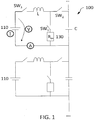
- FIG. 1 shows a block diagram of an exemplary embodiment of a battery module.
- the battery module 100 includes a plurality of battery cells 110, each of which is equipped with an external circuit.
- a battery module 100 for an electric vehicle may include hundreds or thousands of battery cells 110, whereas a battery module 100 for an electric bicycle may include fewer than one hundred battery cells 110.
- the battery cells 110 may be lithium-ion cells, or may have any other suitable chemistry.
- each external circuit may be a DC/DC converter, and may include a first switch SW 1 , a second switch SW 2 , and a third switch SW 3 , which are controlled by a respective controller (not shown).
- Each external circuit may also include an inductor L and a capacitor C.
- each external circuit may include a voltage sensor V that measures the voltage of the respective battery cell 110, a temperature sensor T that measures the temperature of the respective battery cell 110, and a current sensor A that measures the current of the respective battery cell 110. Measurement results from these sensors are output to the controller.
- the third switch SW 3 is continuously closed, while the controller controls the first switch SW 1 and the second switch SW 2 to alternate very quickly between open and closed, such that when the first switch SW 1 is open the second switch SW 2 is closed, and vice versa.
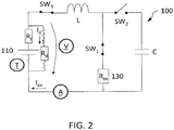
- FIG. 2 shows an exemplary embodiment in which an internal short circuit has occurred within one of the battery cells 110.
- a dendrite may grow from the anode to the cathode of the battery cell 110.
- This dendrite has a resistance R d through which a current I d flows.
- the battery cell 110 also has an internal resistance R i , which is typically in the range of 1-20 m ⁇ for a lithium-ion cell, but may be smaller or larger depending on the size, format, and specific storage chemistry of the battery cell 110.
- the dendrite resistance R d is usually much smaller than the internal resistance R i .
- a heat sink 130 with a resistance R ex is provided external to the battery cell 110. A current I ex flows through the heat sink 130.
- FIGS. 3A and 3B show measurements of characteristics of the battery cell 110 during, before, and after the internal short circuit.
- FIG. 3A shows temperature measurements from the temperature sensor T
- FIG. 3B shows voltage measurements from the voltage sensor V
- the internal short circuit begins at time t 0 .
- the internal short circuit may be detected by any suitable method.
- the internal short circuit may be indicated by a fast voltage drop to a voltage that is below a threshold voltage V min .
- the threshold voltage V min may be defined as an absolute value or as a percentage of the voltage in a normal operating state before the internal short circuit.
- the existence of the internal short circuit may be verified by checking the current of the battery cell 110.
- the internal short circuit may trigger an initial spike in the current. After the initial spike, the current becomes approximately zero, and remains approximately zero while the internal short circuit remains. Accordingly, the existence of the internal short circuit is confirmed by measuring a current that is approximately zero.
- FIG. 3A shows that once the internal short circuit begins at time t 0 , the temperature of the battery cell 110 increases rapidly.
- the controller Upon detecting the internal short circuit, the controller generates an external short circuit by closing the first switch SW 1 and the third switch SW 3 .
- the controller may be a processor, or simple diode-transistor circuits that close the first switch SW 1 and the third switch SW 3 if the cell voltage drops below the threshold voltage V min . This causes at least some of the heat to be generated in the heat sink 130 instead of the battery cell 110.
- the controller may also open the second switch SW 2 in order to interrupt the bus current to the battery cell 110.
- the controller maintains the switches in this configuration until the temperature of the battery cell 110 falls below a temperature threshold.
- the temperature threshold may be any suitable value, such as between 50 and 60 °C, and may depend on the chemistry and the size format of the battery cell 110.
- the resistance R ex of the heat sink 130 may be determined in any suitable manner.
- V cell is the voltage of the battery cell 110 and Z L is the impedance of the inductor L.
- the second switch SW 2 is open.
- the resistance R d of the dendrite depends on various factors, such as the chemistry of the battery cell 110.
- the resistance R ex of the heat sink 130 may be selected such that the ratio shown in Equation (6) is approximately one. In this embodiment, the resistance R ex of the heat sink 130 is selected to be approximately equal to the resistance R d of the dendrite. Alternatively, the resistance R ex of the heat sink 130 may be selected to be smaller than the resistance R d of the dendrite, in order to generate more heat in the heat sink 130 than the battery cell 110. However, even an external resistance R ex that is greater than the resistance R d of the dendrite has a safety advantage compared to a system without such a measure, because less heat will be generated in the battery cell 110 in the event of an internal short circuit.
- the controller may open the second switch SW 2 in order to interrupt the bus current to the battery cell 110. This isolates the affected battery cell 110 from the other battery cells within the battery module 100. If the heat generated by the internal short circuit is not too dangerous, the other battery cells may be allowed to continue operating. In this case a vehicle or an electronic device equipped with the battery module 100 may continue to run. On the other hand, if the heat generated by the internal short circuit is not small enough to be safe, then the bus current to the other battery cells may also be interrupted, such that the vehicle or the electronic device loses power and stops running.
- the battery module may prevent or reduce the risk of a thermal runaway of the battery cell. This reduces the risk of fire in the battery cell and the battery module, thereby improving the safety of the battery module.
- the state-of-charge window of the battery module may be extended, due to the increased reliability of the battery module.
- a non-transitory computer-readable medium encoded with a computer program for operating a battery module.
- the term "computer-readable medium” as used herein refers to any medium that participates in providing instructions for execution. Common forms of computer-readable media include, for example, a floppy disk, a flexible disk, a hard disk, magnetic tape, any other magnetic medium, a CD-ROM, any other optical medium, punch cards, paper tape, any other physical medium with patterns of holes, a RAM, a PROM, an EPROM, a FLASH-EPROM, any other memory chip or cartridge, and any other non-transitory medium from which a computer can read.
Landscapes
- Engineering & Computer Science (AREA)
- Chemical Kinetics & Catalysis (AREA)
- Electrochemistry (AREA)
- General Chemical & Material Sciences (AREA)
- Chemical & Material Sciences (AREA)
- Manufacturing & Machinery (AREA)
- Automation & Control Theory (AREA)
- Physics & Mathematics (AREA)
- Electromagnetism (AREA)
- Life Sciences & Earth Sciences (AREA)
- Sustainable Energy (AREA)
- Power Engineering (AREA)
- Transportation (AREA)
- Mechanical Engineering (AREA)
- Sustainable Development (AREA)
- Secondary Cells (AREA)
Claims (6)
- Procédé de fonctionnement d'un module de batterie, le procédé comprenant :la détection d'un court-circuit interne à l'intérieur d'une cellule de batterie du module de batterie ; etla fermeture d'un premier commutateur à l'intérieur d'un circuit externe connecté à la cellule de batterie afin de générer de la chaleur dans un dissipateur de chaleur à l'intérieur du circuit externe ; etdans lequel le court-circuit interne est détecté si une tension de la cellule de batterie est inférieure à un seuil de tension ; etcomprenant en outre le maintien du premier commutateur dans un état fermé après que le court-circuit interne est détecté, jusqu'à ce qu'une température de la cellule de batterie soit inférieure à un seuil de température ;comprenant en outre la confirmation du court-circuit interne sur la base d'un courant de la cellule de batterie en mesurant un courant de la cellule de batterie qui est approximativement de zéro.
- Procédé selon la revendication 1, comprenant en outre l'ouverture d'un second commutateur à l'intérieur du circuit externe afin d'interrompre un courant de bus vers la cellule de batterie pour électriquement isoler la cellule de batterie par rapport à une pluralité d'autres cellules de batterie à l'intérieur du module de batterie.
- Procédé selon la revendication 2, comprenant en outre l'interruption du courant de bus vers une pluralité d'autres cellules de batterie à l'intérieur du module de batterie.
- Procédé selon la revendication 1, dans lequel une résistance du dissipateur de chaleur est inférieure à une résistance d'une dendrite causant le court-circuit interne.
- Procédé selon la revendication 1, dans lequel une résistance du dissipateur de chaleur est égale ou supérieure à une résistance d'une dendrite causant le court-circuit interne.
- Procédé selon la revendication 4, dans lequel après que le premier commutateur est fermé, plus de chaleur est générée dans le dissipateur de chaleur que dans la cellule de batterie.
Applications Claiming Priority (2)
| Application Number | Priority Date | Filing Date | Title |
|---|---|---|---|
| US14/277,436 US9627678B2 (en) | 2014-05-14 | 2014-05-14 | Battery module with a controllable external heat sink |
| PCT/EP2015/057803 WO2015172947A1 (fr) | 2014-05-14 | 2015-04-10 | Module de batterie à dissipateur de chaleur externe apte à être réglé |
Publications (2)
| Publication Number | Publication Date |
|---|---|
| EP3143655A1 EP3143655A1 (fr) | 2017-03-22 |
| EP3143655B1 true EP3143655B1 (fr) | 2020-09-23 |
Family
ID=52875144
Family Applications (1)
| Application Number | Title | Priority Date | Filing Date |
|---|---|---|---|
| EP15716487.2A Active EP3143655B1 (fr) | 2014-05-14 | 2015-04-10 | Module de batterie à dissipateur de chaleur externe apte à être réglé |
Country Status (4)
| Country | Link |
|---|---|
| US (2) | US9627678B2 (fr) |
| EP (1) | EP3143655B1 (fr) |
| CN (1) | CN106133949A (fr) |
| WO (1) | WO2015172947A1 (fr) |
Families Citing this family (8)
| Publication number | Priority date | Publication date | Assignee | Title |
|---|---|---|---|---|
| KR102752990B1 (ko) | 2017-01-05 | 2025-01-10 | 삼성전자주식회사 | 배터리 팩으로부터 출력된 전력을 제어하는 회로 및 배터리 팩 |
| JP6708148B2 (ja) * | 2017-03-07 | 2020-06-10 | 株式会社オートネットワーク技術研究所 | 車載用電池の保護回路 |
| CN109642929B (zh) * | 2017-08-25 | 2021-07-30 | Oppo广东移动通信有限公司 | 终端设备及其电池异常监控方法和监控系统 |
| EP3657591B1 (fr) * | 2017-08-25 | 2021-07-14 | Guangdong Oppo Mobile Telecommunications Corp., Ltd. | Dispositif terminal et procédé et système de surveillance de sécurité de batterie associés |
| EP3537531B1 (fr) | 2017-11-13 | 2021-08-04 | Guangdong Oppo Mobile Telecommunications Corp., Ltd. | Procédé de surveillance de la sécurité pour adaptateur, dispositif terminal et batterie associée, et système de surveillance |
| CN108983034B (zh) * | 2018-10-26 | 2020-06-05 | 北京经纬恒润科技有限公司 | 一种内短路检测方法及装置 |
| KR102868686B1 (ko) * | 2020-03-27 | 2025-10-02 | 주식회사 엘지에너지솔루션 | 배터리 팩 및 전력 저장 장치 |
| US12469892B2 (en) | 2021-11-12 | 2025-11-11 | Ferrari S.P.A. | Method for the diagnosis of thermal runaway in an electric battery |
Family Cites Families (11)
| Publication number | Priority date | Publication date | Assignee | Title |
|---|---|---|---|---|
| GB2355340A (en) * | 1999-10-15 | 2001-04-18 | Aea Technology Plc | Thermally activated switch mechanism |
| US6531847B1 (en) | 2001-11-07 | 2003-03-11 | Quallion Llc | Safety method, device and system for an energy storage device |
| US6891353B2 (en) * | 2001-11-07 | 2005-05-10 | Quallion Llc | Safety method, device and system for an energy storage device |
| US20040000446A1 (en) * | 2002-07-01 | 2004-01-01 | Barber Harold P. | Seismic signaling apparatus and method for enhancing signal repeatability |
| US7157882B2 (en) * | 2002-11-22 | 2007-01-02 | Milwaukee Electric Tool Corporation | Method and system for battery protection employing a selectively-actuated switch |
| US7780098B2 (en) * | 2006-07-11 | 2010-08-24 | Meadwestvaco Calmar, Inc. | Fan spray pattern indexing nozzle for a trigger sprayer |
| US8080328B2 (en) * | 2006-11-21 | 2011-12-20 | Hitachi Vehicle Energy, Ltd. | Secondary battery module having connection breal off mechanism in case of abnormal battery operation |
| JP2009032506A (ja) * | 2007-07-26 | 2009-02-12 | Panasonic Corp | 非水系電解質二次電池の内部短絡検知方法および装置 |
| JP5289083B2 (ja) * | 2009-02-05 | 2013-09-11 | 三洋電機株式会社 | 二次電池の異常検出装置および二次電池装置 |
| JP5825264B2 (ja) * | 2011-01-21 | 2015-12-02 | 株式会社Gsユアサ | 電池システム |
| CN202111196U (zh) * | 2011-06-30 | 2012-01-11 | 邱海燕 | 具有温度感应开关的电池包 |
-
2014
- 2014-05-14 US US14/277,436 patent/US9627678B2/en active Active
-
2015
- 2015-04-10 WO PCT/EP2015/057803 patent/WO2015172947A1/fr not_active Ceased
- 2015-04-10 CN CN201580014971.4A patent/CN106133949A/zh active Pending
- 2015-04-10 EP EP15716487.2A patent/EP3143655B1/fr active Active
-
2017
- 2017-03-03 US US15/449,375 patent/US10418673B2/en active Active
Non-Patent Citations (1)
| Title |
|---|
| None * |
Also Published As
| Publication number | Publication date |
|---|---|
| WO2015172947A1 (fr) | 2015-11-19 |
| US20170179552A1 (en) | 2017-06-22 |
| US20150333381A1 (en) | 2015-11-19 |
| US9627678B2 (en) | 2017-04-18 |
| US10418673B2 (en) | 2019-09-17 |
| EP3143655A1 (fr) | 2017-03-22 |
| CN106133949A (zh) | 2016-11-16 |
Similar Documents
| Publication | Publication Date | Title |
|---|---|---|
| EP3143655B1 (fr) | Module de batterie à dissipateur de chaleur externe apte à être réglé | |
| US9746526B2 (en) | Battery cell unit and method for determining a complex impedance of a battery cell arranged in a battery cell unit | |
| Cai et al. | Battery internal short detection methodology using cell swelling measurements | |
| US10365312B2 (en) | Method for detection of short circuits within an energy storage device | |
| CN103636030B (zh) | 用于识别安全装置的触发的方法 | |
| US20130179012A1 (en) | Detection of over-current in a battery pack | |
| EP2994989B1 (fr) | Système de pré-charge et d'alimentation de tension pour un onduleur cc-ca | |
| JP5791819B2 (ja) | 車載用蓄電装置及びその制御方法 | |
| CN105589046A (zh) | 一种动力电池组热失控扩散的检测警报方法 | |
| US9362544B2 (en) | Systems and methods for control of a current interruption component in a battery system | |
| CN103580097A (zh) | 用于控制蓄电池系统的方法、蓄电池系统和机动车 | |
| US8593110B2 (en) | Device and method of battery discharge | |
| CN102694404A (zh) | 一种动力锂电池组的控制方法、控制模块及控制系统 | |
| EP4300106A1 (fr) | Procédé de diagnostic de panne de bloc-batterie et bloc-batterie | |
| US11600990B2 (en) | Protection system for protecting a battery system | |
| KR20180049899A (ko) | 고장전류 저감회로를 포함하는 집합전지 시스템 | |
| CN106532157A (zh) | 具有过量充电保护和/或过度放电保护的电池组系统 | |
| CN103825253A (zh) | 电动车电池安全控制装置及控制方法 | |
| CN105189183A (zh) | 用于提高在使用蓄电池模块时的安全性的方法和装置 | |
| EP2829431B1 (fr) | Dispositif de détection d'anomalies | |
| CN120826813A (zh) | 电池保护冗余 | |
| CN104052097B (zh) | 蓄电池模块以及用于监控蓄电池模块的方法 | |
| KR20160134601A (ko) | 스마트폰 리튬이온 배터리 폭발방지 및 안전을 위한 시스템 | |
| CN103443967A (zh) | 带电流中断装置的电化学储能单元 | |
| JP2015061505A (ja) | 蓄電システム |
Legal Events
| Date | Code | Title | Description |
|---|---|---|---|
| STAA | Information on the status of an ep patent application or granted ep patent |
Free format text: STATUS: THE INTERNATIONAL PUBLICATION HAS BEEN MADE |
|
| PUAI | Public reference made under article 153(3) epc to a published international application that has entered the european phase |
Free format text: ORIGINAL CODE: 0009012 |
|
| STAA | Information on the status of an ep patent application or granted ep patent |
Free format text: STATUS: REQUEST FOR EXAMINATION WAS MADE |
|
| 17P | Request for examination filed |
Effective date: 20160929 |
|
| AK | Designated contracting states |
Kind code of ref document: A1 Designated state(s): AL AT BE BG CH CY CZ DE DK EE ES FI FR GB GR HR HU IE IS IT LI LT LU LV MC MK MT NL NO PL PT RO RS SE SI SK SM TR |
|
| AX | Request for extension of the european patent |
Extension state: BA ME |
|
| DAV | Request for validation of the european patent (deleted) | ||
| DAX | Request for extension of the european patent (deleted) | ||
| STAA | Information on the status of an ep patent application or granted ep patent |
Free format text: STATUS: EXAMINATION IS IN PROGRESS |
|
| 17Q | First examination report despatched |
Effective date: 20180328 |
|
| GRAP | Despatch of communication of intention to grant a patent |
Free format text: ORIGINAL CODE: EPIDOSNIGR1 |
|
| STAA | Information on the status of an ep patent application or granted ep patent |
Free format text: STATUS: GRANT OF PATENT IS INTENDED |
|
| RIC1 | Information provided on ipc code assigned before grant |
Ipc: H01M 10/6551 20140101ALI20200421BHEP Ipc: H01M 10/613 20140101ALI20200421BHEP Ipc: H01M 10/625 20140101ALI20200421BHEP Ipc: B60L 58/26 20190101ALI20200421BHEP Ipc: H01M 2/34 20060101AFI20200421BHEP Ipc: H01M 10/637 20140101ALI20200421BHEP Ipc: H01M 10/657 20140101ALI20200421BHEP Ipc: H01M 10/42 20060101ALI20200421BHEP |
|
| INTG | Intention to grant announced |
Effective date: 20200511 |
|
| GRAS | Grant fee paid |
Free format text: ORIGINAL CODE: EPIDOSNIGR3 |
|
| GRAA | (expected) grant |
Free format text: ORIGINAL CODE: 0009210 |
|
| STAA | Information on the status of an ep patent application or granted ep patent |
Free format text: STATUS: THE PATENT HAS BEEN GRANTED |
|
| AK | Designated contracting states |
Kind code of ref document: B1 Designated state(s): AL AT BE BG CH CY CZ DE DK EE ES FI FR GB GR HR HU IE IS IT LI LT LU LV MC MK MT NL NO PL PT RO RS SE SI SK SM TR |
|
| REG | Reference to a national code |
Ref country code: GB Ref legal event code: FG4D |
|
| REG | Reference to a national code |
Ref country code: CH Ref legal event code: EP |
|
| REG | Reference to a national code |
Ref country code: DE Ref legal event code: R096 Ref document number: 602015059470 Country of ref document: DE |
|
| REG | Reference to a national code |
Ref country code: IE Ref legal event code: FG4D |
|
| REG | Reference to a national code |
Ref country code: AT Ref legal event code: REF Ref document number: 1317295 Country of ref document: AT Kind code of ref document: T Effective date: 20201015 |
|
| REG | Reference to a national code |
Ref country code: DE Ref legal event code: R079 Ref document number: 602015059470 Country of ref document: DE Free format text: PREVIOUS MAIN CLASS: H01M0002340000 Ipc: H01M0050572000 |
|
| PG25 | Lapsed in a contracting state [announced via postgrant information from national office to epo] |
Ref country code: HR Free format text: LAPSE BECAUSE OF FAILURE TO SUBMIT A TRANSLATION OF THE DESCRIPTION OR TO PAY THE FEE WITHIN THE PRESCRIBED TIME-LIMIT Effective date: 20200923 Ref country code: BG Free format text: LAPSE BECAUSE OF FAILURE TO SUBMIT A TRANSLATION OF THE DESCRIPTION OR TO PAY THE FEE WITHIN THE PRESCRIBED TIME-LIMIT Effective date: 20201223 Ref country code: NO Free format text: LAPSE BECAUSE OF FAILURE TO SUBMIT A TRANSLATION OF THE DESCRIPTION OR TO PAY THE FEE WITHIN THE PRESCRIBED TIME-LIMIT Effective date: 20201223 Ref country code: GR Free format text: LAPSE BECAUSE OF FAILURE TO SUBMIT A TRANSLATION OF THE DESCRIPTION OR TO PAY THE FEE WITHIN THE PRESCRIBED TIME-LIMIT Effective date: 20201224 Ref country code: FI Free format text: LAPSE BECAUSE OF FAILURE TO SUBMIT A TRANSLATION OF THE DESCRIPTION OR TO PAY THE FEE WITHIN THE PRESCRIBED TIME-LIMIT Effective date: 20200923 Ref country code: SE Free format text: LAPSE BECAUSE OF FAILURE TO SUBMIT A TRANSLATION OF THE DESCRIPTION OR TO PAY THE FEE WITHIN THE PRESCRIBED TIME-LIMIT Effective date: 20200923 |
|
| REG | Reference to a national code |
Ref country code: AT Ref legal event code: MK05 Ref document number: 1317295 Country of ref document: AT Kind code of ref document: T Effective date: 20200923 |
|
| PG25 | Lapsed in a contracting state [announced via postgrant information from national office to epo] |
Ref country code: RS Free format text: LAPSE BECAUSE OF FAILURE TO SUBMIT A TRANSLATION OF THE DESCRIPTION OR TO PAY THE FEE WITHIN THE PRESCRIBED TIME-LIMIT Effective date: 20200923 Ref country code: LV Free format text: LAPSE BECAUSE OF FAILURE TO SUBMIT A TRANSLATION OF THE DESCRIPTION OR TO PAY THE FEE WITHIN THE PRESCRIBED TIME-LIMIT Effective date: 20200923 |
|
| REG | Reference to a national code |
Ref country code: NL Ref legal event code: MP Effective date: 20200923 |
|
| REG | Reference to a national code |
Ref country code: LT Ref legal event code: MG4D |
|
| PG25 | Lapsed in a contracting state [announced via postgrant information from national office to epo] |
Ref country code: CZ Free format text: LAPSE BECAUSE OF FAILURE TO SUBMIT A TRANSLATION OF THE DESCRIPTION OR TO PAY THE FEE WITHIN THE PRESCRIBED TIME-LIMIT Effective date: 20200923 Ref country code: PT Free format text: LAPSE BECAUSE OF FAILURE TO SUBMIT A TRANSLATION OF THE DESCRIPTION OR TO PAY THE FEE WITHIN THE PRESCRIBED TIME-LIMIT Effective date: 20210125 Ref country code: NL Free format text: LAPSE BECAUSE OF FAILURE TO SUBMIT A TRANSLATION OF THE DESCRIPTION OR TO PAY THE FEE WITHIN THE PRESCRIBED TIME-LIMIT Effective date: 20200923 Ref country code: LT Free format text: LAPSE BECAUSE OF FAILURE TO SUBMIT A TRANSLATION OF THE DESCRIPTION OR TO PAY THE FEE WITHIN THE PRESCRIBED TIME-LIMIT Effective date: 20200923 Ref country code: EE Free format text: LAPSE BECAUSE OF FAILURE TO SUBMIT A TRANSLATION OF THE DESCRIPTION OR TO PAY THE FEE WITHIN THE PRESCRIBED TIME-LIMIT Effective date: 20200923 Ref country code: RO Free format text: LAPSE BECAUSE OF FAILURE TO SUBMIT A TRANSLATION OF THE DESCRIPTION OR TO PAY THE FEE WITHIN THE PRESCRIBED TIME-LIMIT Effective date: 20200923 Ref country code: SM Free format text: LAPSE BECAUSE OF FAILURE TO SUBMIT A TRANSLATION OF THE DESCRIPTION OR TO PAY THE FEE WITHIN THE PRESCRIBED TIME-LIMIT Effective date: 20200923 |
|
| PG25 | Lapsed in a contracting state [announced via postgrant information from national office to epo] |
Ref country code: ES Free format text: LAPSE BECAUSE OF FAILURE TO SUBMIT A TRANSLATION OF THE DESCRIPTION OR TO PAY THE FEE WITHIN THE PRESCRIBED TIME-LIMIT Effective date: 20200923 Ref country code: AT Free format text: LAPSE BECAUSE OF FAILURE TO SUBMIT A TRANSLATION OF THE DESCRIPTION OR TO PAY THE FEE WITHIN THE PRESCRIBED TIME-LIMIT Effective date: 20200923 Ref country code: AL Free format text: LAPSE BECAUSE OF FAILURE TO SUBMIT A TRANSLATION OF THE DESCRIPTION OR TO PAY THE FEE WITHIN THE PRESCRIBED TIME-LIMIT Effective date: 20200923 Ref country code: IS Free format text: LAPSE BECAUSE OF FAILURE TO SUBMIT A TRANSLATION OF THE DESCRIPTION OR TO PAY THE FEE WITHIN THE PRESCRIBED TIME-LIMIT Effective date: 20210123 Ref country code: PL Free format text: LAPSE BECAUSE OF FAILURE TO SUBMIT A TRANSLATION OF THE DESCRIPTION OR TO PAY THE FEE WITHIN THE PRESCRIBED TIME-LIMIT Effective date: 20200923 |
|
| REG | Reference to a national code |
Ref country code: DE Ref legal event code: R097 Ref document number: 602015059470 Country of ref document: DE |
|
| PG25 | Lapsed in a contracting state [announced via postgrant information from national office to epo] |
Ref country code: SK Free format text: LAPSE BECAUSE OF FAILURE TO SUBMIT A TRANSLATION OF THE DESCRIPTION OR TO PAY THE FEE WITHIN THE PRESCRIBED TIME-LIMIT Effective date: 20200923 |
|
| PLBE | No opposition filed within time limit |
Free format text: ORIGINAL CODE: 0009261 |
|
| STAA | Information on the status of an ep patent application or granted ep patent |
Free format text: STATUS: NO OPPOSITION FILED WITHIN TIME LIMIT |
|
| PG25 | Lapsed in a contracting state [announced via postgrant information from national office to epo] |
Ref country code: SI Free format text: LAPSE BECAUSE OF FAILURE TO SUBMIT A TRANSLATION OF THE DESCRIPTION OR TO PAY THE FEE WITHIN THE PRESCRIBED TIME-LIMIT Effective date: 20200923 Ref country code: DK Free format text: LAPSE BECAUSE OF FAILURE TO SUBMIT A TRANSLATION OF THE DESCRIPTION OR TO PAY THE FEE WITHIN THE PRESCRIBED TIME-LIMIT Effective date: 20200923 |
|
| 26N | No opposition filed |
Effective date: 20210624 |
|
| PG25 | Lapsed in a contracting state [announced via postgrant information from national office to epo] |
Ref country code: IT Free format text: LAPSE BECAUSE OF FAILURE TO SUBMIT A TRANSLATION OF THE DESCRIPTION OR TO PAY THE FEE WITHIN THE PRESCRIBED TIME-LIMIT Effective date: 20200923 |
|
| PG25 | Lapsed in a contracting state [announced via postgrant information from national office to epo] |
Ref country code: MC Free format text: LAPSE BECAUSE OF FAILURE TO SUBMIT A TRANSLATION OF THE DESCRIPTION OR TO PAY THE FEE WITHIN THE PRESCRIBED TIME-LIMIT Effective date: 20200923 |
|
| GBPC | Gb: european patent ceased through non-payment of renewal fee |
Effective date: 20210410 |
|
| PG25 | Lapsed in a contracting state [announced via postgrant information from national office to epo] |
Ref country code: LU Free format text: LAPSE BECAUSE OF NON-PAYMENT OF DUE FEES Effective date: 20210410 |
|
| REG | Reference to a national code |
Ref country code: BE Ref legal event code: MM Effective date: 20210430 |
|
| PG25 | Lapsed in a contracting state [announced via postgrant information from national office to epo] |
Ref country code: CH Free format text: LAPSE BECAUSE OF NON-PAYMENT OF DUE FEES Effective date: 20210430 Ref country code: LI Free format text: LAPSE BECAUSE OF NON-PAYMENT OF DUE FEES Effective date: 20210430 Ref country code: GB Free format text: LAPSE BECAUSE OF NON-PAYMENT OF DUE FEES Effective date: 20210410 Ref country code: FR Free format text: LAPSE BECAUSE OF NON-PAYMENT OF DUE FEES Effective date: 20210430 |
|
| PG25 | Lapsed in a contracting state [announced via postgrant information from national office to epo] |
Ref country code: IE Free format text: LAPSE BECAUSE OF NON-PAYMENT OF DUE FEES Effective date: 20210410 |
|
| PG25 | Lapsed in a contracting state [announced via postgrant information from national office to epo] |
Ref country code: IS Free format text: LAPSE BECAUSE OF FAILURE TO SUBMIT A TRANSLATION OF THE DESCRIPTION OR TO PAY THE FEE WITHIN THE PRESCRIBED TIME-LIMIT Effective date: 20210123 |
|
| PG25 | Lapsed in a contracting state [announced via postgrant information from national office to epo] |
Ref country code: BE Free format text: LAPSE BECAUSE OF NON-PAYMENT OF DUE FEES Effective date: 20210430 |
|
| PG25 | Lapsed in a contracting state [announced via postgrant information from national office to epo] |
Ref country code: HU Free format text: LAPSE BECAUSE OF FAILURE TO SUBMIT A TRANSLATION OF THE DESCRIPTION OR TO PAY THE FEE WITHIN THE PRESCRIBED TIME-LIMIT; INVALID AB INITIO Effective date: 20150410 |
|
| P01 | Opt-out of the competence of the unified patent court (upc) registered |
Effective date: 20230427 |
|
| PG25 | Lapsed in a contracting state [announced via postgrant information from national office to epo] |
Ref country code: CY Free format text: LAPSE BECAUSE OF FAILURE TO SUBMIT A TRANSLATION OF THE DESCRIPTION OR TO PAY THE FEE WITHIN THE PRESCRIBED TIME-LIMIT Effective date: 20200923 |
|
| PG25 | Lapsed in a contracting state [announced via postgrant information from national office to epo] |
Ref country code: MK Free format text: LAPSE BECAUSE OF FAILURE TO SUBMIT A TRANSLATION OF THE DESCRIPTION OR TO PAY THE FEE WITHIN THE PRESCRIBED TIME-LIMIT Effective date: 20200923 |
|
| PG25 | Lapsed in a contracting state [announced via postgrant information from national office to epo] |
Ref country code: MT Free format text: LAPSE BECAUSE OF FAILURE TO SUBMIT A TRANSLATION OF THE DESCRIPTION OR TO PAY THE FEE WITHIN THE PRESCRIBED TIME-LIMIT Effective date: 20200923 |
|
| PGFP | Annual fee paid to national office [announced via postgrant information from national office to epo] |
Ref country code: DE Payment date: 20250408 Year of fee payment: 11 |
|
| PG25 | Lapsed in a contracting state [announced via postgrant information from national office to epo] |
Ref country code: TR Free format text: LAPSE BECAUSE OF FAILURE TO SUBMIT A TRANSLATION OF THE DESCRIPTION OR TO PAY THE FEE WITHIN THE PRESCRIBED TIME-LIMIT Effective date: 20200923 |