EP3143668B1 - Dispositif de raccordement d'un circuit ou d'un composant radiofrequence imprime sur un support souple a un cable coaxial - Google Patents
Dispositif de raccordement d'un circuit ou d'un composant radiofrequence imprime sur un support souple a un cable coaxial Download PDFInfo
- Publication number
- EP3143668B1 EP3143668B1 EP15721282.0A EP15721282A EP3143668B1 EP 3143668 B1 EP3143668 B1 EP 3143668B1 EP 15721282 A EP15721282 A EP 15721282A EP 3143668 B1 EP3143668 B1 EP 3143668B1
- Authority
- EP
- European Patent Office
- Prior art keywords
- piece
- support
- face
- coaxial cable
- connector
- Prior art date
- Legal status (The legal status is an assumption and is not a legal conclusion. Google has not performed a legal analysis and makes no representation as to the accuracy of the status listed.)
- Active
Links
Images


Classifications
-
- H—ELECTRICITY
- H01—ELECTRIC ELEMENTS
- H01R—ELECTRICALLY-CONDUCTIVE CONNECTIONS; STRUCTURAL ASSOCIATIONS OF A PLURALITY OF MUTUALLY-INSULATED ELECTRICAL CONNECTING ELEMENTS; COUPLING DEVICES; CURRENT COLLECTORS
- H01R12/00—Structural associations of a plurality of mutually-insulated electrical connecting elements, specially adapted for printed circuits, e.g. printed circuit boards [PCB], flat or ribbon cables, or like generally planar structures, e.g. terminal strips, terminal blocks; Coupling devices specially adapted for printed circuits, flat or ribbon cables, or like generally planar structures; Terminals specially adapted for contact with, or insertion into, printed circuits, flat or ribbon cables, or like generally planar structures
- H01R12/70—Coupling devices
- H01R12/7005—Guiding, mounting, polarizing or locking means; Extractors
- H01R12/7011—Locking or fixing a connector to a PCB
- H01R12/7064—Press fitting
-
- H—ELECTRICITY
- H01—ELECTRIC ELEMENTS
- H01R—ELECTRICALLY-CONDUCTIVE CONNECTIONS; STRUCTURAL ASSOCIATIONS OF A PLURALITY OF MUTUALLY-INSULATED ELECTRICAL CONNECTING ELEMENTS; COUPLING DEVICES; CURRENT COLLECTORS
- H01R12/00—Structural associations of a plurality of mutually-insulated electrical connecting elements, specially adapted for printed circuits, e.g. printed circuit boards [PCB], flat or ribbon cables, or like generally planar structures, e.g. terminal strips, terminal blocks; Coupling devices specially adapted for printed circuits, flat or ribbon cables, or like generally planar structures; Terminals specially adapted for contact with, or insertion into, printed circuits, flat or ribbon cables, or like generally planar structures
- H01R12/70—Coupling devices
- H01R12/7076—Coupling devices for connection between PCB and component, e.g. display
-
- H—ELECTRICITY
- H01—ELECTRIC ELEMENTS
- H01Q—ANTENNAS, i.e. RADIO AERIALS
- H01Q1/00—Details of, or arrangements associated with, antennas
- H01Q1/36—Structural form of radiating elements, e.g. cone, spiral, umbrella; Particular materials used therewith
- H01Q1/38—Structural form of radiating elements, e.g. cone, spiral, umbrella; Particular materials used therewith formed by a conductive layer on an insulating support
-
- H—ELECTRICITY
- H01—ELECTRIC ELEMENTS
- H01Q—ANTENNAS, i.e. RADIO AERIALS
- H01Q7/00—Loop antennas with a substantially uniform current distribution around the loop and having a directional radiation pattern in a plane perpendicular to the plane of the loop
-
- H—ELECTRICITY
- H01—ELECTRIC ELEMENTS
- H01R—ELECTRICALLY-CONDUCTIVE CONNECTIONS; STRUCTURAL ASSOCIATIONS OF A PLURALITY OF MUTUALLY-INSULATED ELECTRICAL CONNECTING ELEMENTS; COUPLING DEVICES; CURRENT COLLECTORS
- H01R12/00—Structural associations of a plurality of mutually-insulated electrical connecting elements, specially adapted for printed circuits, e.g. printed circuit boards [PCB], flat or ribbon cables, or like generally planar structures, e.g. terminal strips, terminal blocks; Coupling devices specially adapted for printed circuits, flat or ribbon cables, or like generally planar structures; Terminals specially adapted for contact with, or insertion into, printed circuits, flat or ribbon cables, or like generally planar structures
- H01R12/70—Coupling devices
- H01R12/77—Coupling devices for flexible printed circuits, flat or ribbon cables or like structures
- H01R12/81—Coupling devices for flexible printed circuits, flat or ribbon cables or like structures connecting to another cable except for flat or ribbon cable
-
- H—ELECTRICITY
- H01—ELECTRIC ELEMENTS
- H01R—ELECTRICALLY-CONDUCTIVE CONNECTIONS; STRUCTURAL ASSOCIATIONS OF A PLURALITY OF MUTUALLY-INSULATED ELECTRICAL CONNECTING ELEMENTS; COUPLING DEVICES; CURRENT COLLECTORS
- H01R24/00—Two-part coupling devices, or either of their cooperating parts, characterised by their overall structure
- H01R24/38—Two-part coupling devices, or either of their cooperating parts, characterised by their overall structure having concentrically or coaxially arranged contacts
- H01R24/40—Two-part coupling devices, or either of their cooperating parts, characterised by their overall structure having concentrically or coaxially arranged contacts specially adapted for high frequency
- H01R24/50—Two-part coupling devices, or either of their cooperating parts, characterised by their overall structure having concentrically or coaxially arranged contacts specially adapted for high frequency mounted on a PCB [Printed Circuit Board]
-
- H—ELECTRICITY
- H01—ELECTRIC ELEMENTS
- H01R—ELECTRICALLY-CONDUCTIVE CONNECTIONS; STRUCTURAL ASSOCIATIONS OF A PLURALITY OF MUTUALLY-INSULATED ELECTRICAL CONNECTING ELEMENTS; COUPLING DEVICES; CURRENT COLLECTORS
- H01R2103/00—Two poles
-
- H—ELECTRICITY
- H01—ELECTRIC ELEMENTS
- H01R—ELECTRICALLY-CONDUCTIVE CONNECTIONS; STRUCTURAL ASSOCIATIONS OF A PLURALITY OF MUTUALLY-INSULATED ELECTRICAL CONNECTING ELEMENTS; COUPLING DEVICES; CURRENT COLLECTORS
- H01R2201/00—Connectors or connections adapted for particular applications
- H01R2201/02—Connectors or connections adapted for particular applications for antennas
Definitions
- the invention relates to a device for connecting a circuit or radiofrequency component printed on a flexible support, to a coaxial cable.
- This electronic radiocommunication equipment generally comprises radiofrequency components, including in particular a radio antenna type "whip antenna”. However, these antennas can be bulky.
- these antennas In addition, to be able to function effectively, these antennas must be positioned vertically. Thus, these antennas lose their effectiveness as soon as the fighter is in a supine position.
- whip antennas with antennas integrated in the protective clothing, for example by printing the antenna and the antenna supply circuit directly on a part of the garment, such as on a piece of fabric.
- the part of the garment thus serves as support for the antenna and the power supply circuit.
- connection connector for electrically connecting the electronic communication equipment to the antenna printed on the support.
- Such a connector is for example described in the patent EP1760825A1 .
- An object of the invention is to provide a connection device adapted to connect a circuit or a radiofrequency component printed on a flexible support to a coaxial cable.
- the proposed device makes it possible to connect the printed radio frequency circuit or component to the coaxial cable, without damaging the flexible support.
- the proposed device allows the use of a standard connector, already qualified for the intended applications.
- the antenna assembly 1 shown comprises a support 2, an antenna circuit 3 printed on the support 2 and a connection device 4 for electrically connecting the printed circuit 3 to a coaxial cable (not shown).
- the antenna circuit 3 may include a radiating portion forming the antenna and a feeding portion for feeding the antenna.
- the support 2 is in the form of a flat, thin sheet formed of a flexible material, such as fabric or a flexible plastic material (for example a polyimide).
- the support 2 has a first face 5 and a second face 6, opposite to the first face.
- the circuit 3 comprises one or more conductive tracks printed on the first face 5 of the support.
- the circuit 3 comprises two conductive tracks 7 and 8 printed on the support 2.
- Each conductive track 7, respectively 8, comprises a first end 9, respectively 10, and a second end 11, respectively 12.
- the connecting device 4 comprises a coaxial cable connector 13, a first piece 14 (or interface piece) and a second piece 15 (or counterpart).
- the first part 14 is in contact with the first face 5 of the support 2 and the second part 15 is in contact with the second face 6 of the support 2.
- the support 2 is is located interposed between the two parts 14 and 15. The support 2 extends continuously between the two parts 14 and 15.
- the first piece 14 and the second piece 15 may be formed of flexible plastic material, such as rubber for example.
- Each of the parts 14 and 15 is formed of a single piece of material, for example by molding.
- the coaxial cable connector 13 is a bent connector.
- the connector 13 comprises a body 16, a connection socket 17 of a coaxial cable and contact pads 18 to 21.
- the branch plug 17 comprises a tubular portion 22 adapted to receive an end of a coaxial cable in a branch direction X, parallel to the plane of the support 2.
- the tubular portion 22 has a threaded outer surface, allowing the end to be screwed on. cable on the connection socket 17.
- the contact pads 18 to 21 extend projecting from the body 16 in a direction Y, substantially perpendicular to the X direction of connection of the coaxial cable. In the example shown on the figure 2 the contact pads 18 to 21 are four in number.
- the first piece 14 (or interface piece) is designed to encapsulate the connector 13.
- the first piece 14 comprises a cavity 23 adapted to house the connector 13.
- the first piece 14 comprises a first opening 24 through which extends the connection socket 17 of the connector 13 to connect the coaxial cable and a second opening 25 through which contact pads 18 to 21 extend to come into contact with the antenna tracks.
- the first opening 24 has a circular shape allowing the passage of the tubular portion 22 through the first opening 24.
- the first piece 14 further comprises a substantially flat portion 26 (or first plate) having a first planar face 27 intended to come into contact with the first face 5 of the support 2, and a bulged portion 28 extending projecting from the flat portion 26 and surrounding the cavity 23.
- the bulged portion 28 has a curved outer surface 29.
- the second opening 25 is formed in the first face 27.
- the second opening 25 has a substantially rectangular shape.
- the second opening 25 is configured so that, during assembly of the connecting device 4, the connector 13 can be inserted into the cavity 23 by the second opening 25.
- the first piece 14 comprises a plurality of fixing pins 30 to 36 projecting from the first face 27.
- the second part (or counterpart) comprises a flat part 37 (or second plate) having a second planar face 38 intended to come into contact with the second face 6 of the support 2.
- the flat part 37 of the second part 15 has dimensions substantially identical to the dimensions of the flat portion 26 of the first piece 14.
- the second part 15 further comprises fixing holes 40 to 46 formed through the flat part 37.
- Each attachment pin 30 to 36 of the first piece 14 is adapted to be inserted into a corresponding fixing orifice 40 to 46 of the second piece 15 to fix the first piece 14 and the second piece 15 between them.
- the connecting device 4 is mounted on the support 2 in the following manner.
- the connector 13 is first inserted into the cavity 23 of the first piece 14 via the second opening 25.
- the branching plug 17 is introduced into the cavity 23 via the second opening 25 and then passed through the first opening. opening 24, so as to project out of the first piece 14.
- the contact pads 18 to 21 of the connector 13 protrude from the first piece 14 through the second opening 25 on the side of the first face 27.
- the first part 14 is then positioned against the first face 5 of the support 2. More specifically, the first face 27 of the first part 14 is in contact with the first face 5 of the support 2.
- the first part 14 is positioned so that each contact pad 18 to 21 is in contact with an end 9 to 12 of a conductive track 7, 8. Specifically, each contact pad 18, 19, 20 and 21 is is in contact with the ends 9, 10, 11 and 12 respectively.
- the second part 15 is positioned in contact with the second face 6 of the support 2. More specifically, the second face 38 of the second part 15 is in contact with the second face 6 of the support 2.
- the support 2 extends continuously between the two parts 14 and 15 of the device, without being deformed.
- first piece 14 and the second piece 15 are pressed towards each other, so that the attachment studs 30 to 36 of the first piece 14 pass through the support 2 and are plugged into the fixing holes 40 to 46 of the second room 15.
- the fixing pins 30 to 36 may be forcefully inserted into the fixing holes 40 to 46 so as to fix the first piece 14 and the second piece 15 between them.
- the fixing pins 30 to 36 can be crimped into the fixing orifices 40 to 46, once the fixing pins 30 to 36 have been inserted into the fixing orifices 40 to 46.
- the support 2 is clamped between the first part 14 and the second part 15, which makes it possible to maintain electrical contact between the contact pads 18 to 21 and the contacts.
- a coaxial connection cable can be connected to the socket 17.
- connection device 4 makes it possible to limit the risks of tearing of the support 2 in the event of tension exerted on the coaxial cable.
- the first piece 14 limits the discomfort created by the presence of the connecting device projecting from the support 2.
Landscapes
- Multi-Conductor Connections (AREA)
- Coupling Device And Connection With Printed Circuit (AREA)
Description
- L'invention concerne un dispositif de raccordement d'un circuit ou composant radiofréquence imprimé sur un support souple, à un câble coaxial.
- Les combattants à pied sont désormais équipés de vêtements de protection qui incorporent du matériel électronique de radiocommunication. Ce matériel électronique de radiocommunication comprend généralement des composants radiofréquence, incluant notamment une antenne radiofréquence de type « antenne fouet ». Cependant, ces antennes peuvent être encombrantes.
- De plus, pour pouvoir fonctionner efficacement, ces antennes doivent être positionnées verticalement. Ainsi, ces antennes perdent leur efficacité dès que le combattant se trouve en position couchée.
- Il serait envisageable de remplacer ces antennes fouet par des antennes intégrées dans le vêtement de protection, par exemple en imprimant l'antenne et le circuit d'alimentation de l'antenne directement sur une partie du vêtement, tel que sur une pièce de tissu. La partie du vêtement servirait ainsi de support pour l'antenne et le circuit d'alimentation.
- Cependant, cette solution nécessiterait de concevoir un connecteur de raccordement spécifique pour raccorder électriquement le matériel électronique de communication à l'antenne imprimée sur le support. Un tel connecteur est par exemple décrit dans le brevet
EP1760825A1 . - La conception d'un tel connecteur est d'autant plus complexe que le support est un support souple tandis que le connecteur est nécessairement rigide. Ainsi, une fixation du connecteur par collage ou soudure directement sur le support souple risquerait à la longue de générer une déchirure du support souple.
- Un but de l'invention est de proposer un dispositif de raccordement adapté pour raccorder un circuit ou un composant radiofréquence imprimé sur un support souple à un câble coaxial.
- Ce but est atteint par un dispositif de raccordement qui présente les caractéristiques énoncées à la revendication 1.
- Comme les pièces sont fixées sur le support souple par serrage, le dispositif proposé permet de raccorder le circuit ou le composant radiofréquence imprimé au câble coaxial, sans endommager le support souple.
- De plus, le dispositif proposé autorise l'utilisation d'un connecteur standard, déjà qualifié pour les applications envisagées.
- Le dispositif peut en outre présenter les caractéristiques suivantes :
- la première pièce présente une première face plane disposée en contact avec la première face du support lorsque la première pièce est disposée contre la première face du support,
- la deuxième pièce présente une deuxième face plane disposée en contact avec la deuxième face du support lorsque la deuxième pièce est disposée contre la deuxième face du support,
- les moyens de fixation comprennent des orifices de fixation formés dans l'une des pièces et des pions de fixation formés dans l'autre des pièces et propre à être insérés dans les orifices de fixation pour fixer la première pièce et la deuxième pièce entre elles,
- les pions s'étendent à travers le support souple lorsque la première pièce et la deuxième pièce sont fixées entre elles, le support souple étant serré entre la première pièce et la deuxième pièce,
- la prise de branchement d'un câble coaxial est adaptée pour brancher le câble coaxial selon une direction de branchement sensiblement parallèle à la première face du support,
- le connecteur du câble comprend une surface filetée pour visser le câble coaxiale sur le connecteur,
- les plots de contact s'étendent selon une direction sensiblement perpendiculaire à la première face du support,
- la première pièce comprend une partie sensiblement plane propre à venir en contact avec la première face du support et une partie renflée entourant la cavité et s'étendant en saillie de la partie plane, la partie renflée présentant une surface externe courbe.
- D'autres caractéristiques et avantages ressortiront encore de la description qui suit, laquelle est purement illustrative, et non limitative, et doit être lue en regard des figures annexées, parmi lesquelles :
- la
figure 1 représente de manière schématique un ensemble d'antenne comprenant un circuit imprimé et un dispositif de raccordement conforme à un mode de réalisation de l'invention, - la
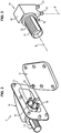
figure 2 représente de manière schématique les différentes pièces du dispositif de raccordement, - la
figure 3 représente de manière schématique un connecteur de câble coaxial du dispositif de raccordement, - les
figures 4A à 4D représentent de manière schématique une première pièce du dispositif de raccordement, - les
figures 5A à 5C représentent de manière schématique une deuxième pièce du dispositif de raccordement. - Sur la
figure 1 , l'ensemble d'antenne 1 représenté comprend un support 2, un circuit d'antenne 3 imprimé sur le support 2 et un dispositif de raccordement 4 permettant de raccorder électriquement le circuit 3 imprimé à un câble coaxial (non-représenté). Le circuit d'antenne 3 peut inclure une partie rayonnante formant l'antenne et une partie d'alimentation pour l'alimentation de l'antenne. - Le support 2 présente la forme d'une feuille mince, plane, formée en un matériau souple, tel que du tissu ou un matériau plastique souple (par exemple un polyimide). Le support 2 présente une première face 5 et une deuxième face 6, opposée à la première face.
- Le circuit 3 comprend une ou plusieurs pistes conductrices imprimées sur la première face 5 du support. Sur l'exemple représenté sur la
figure 1 , le circuit 3 comprend deux pistes conductrices 7 et 8 imprimées sur le support 2. Chaque piste conductrice 7, respectivement 8, comprend une première extrémité 9, respectivement 10, et une deuxième extrémité 11, respectivement 12. - Le dispositif de raccordement 4 comprend un connecteur de câble coaxial 13, une première pièce 14 (ou pièce d'interface) et une deuxième pièce 15 (ou contre-pièce).
- Lorsque le dispositif 4 est monté sur le support 2, la première pièce 14 est en contact avec la première face 5 du support 2 et la deuxième pièce 15 est en contact avec la deuxième face 6 du support 2. Le support 2 se trouve interposé entre les deux pièces 14 et 15. Le support 2 s'étend continument entre les deux pièces 14 et 15.
- La première pièce 14 et la deuxième pièce 15 peuvent être formées en matière plastique souple, tel qu'en caoutchouc par exemple. Chacune des pièces 14 et 15 est formée en une seule pièce de matériau, par exemple par moulage.
- Comme illustré sur les
figures 2 et 3 , le connecteur de câble coaxial 13 est un connecteur de forme coudée. Le connecteur 13 comprend un corps 16, une prise de branchement 17 d'un câble coaxial et des plots de contact 18 à 21. - La prise de branchement 17 comprend une partie tubulaire 22 adaptée pour recevoir une extrémité d'un câble coaxial selon une direction de branchement X, parallèle au plan du support 2. La partie tubulaire 22 présente une surface externe filetée, permettant de visser l'extrémité du câble sur la prise de branchement 17.
- Les plots de contact 18 à 21 s'étendent en saillie du corps 16 selon une direction Y, sensiblement perpendiculaire à la direction X de branchement du câble coaxial. Dans l'exemple illustré sur la
figure 2 , les plots de contact 18 à 21 sont au nombre de quatre. - Comme illustré sur les
figures 4A à 4D , la première pièce 14 (ou pièce d'interface) est conçue pour encapsuler le connecteur 13. A cet effet, la première pièce 14 comprend une cavité 23 adaptée pour loger le connecteur 13. Par ailleurs, la première pièce 14 comprend une première ouverture 24 à travers laquelle s'étend la prise de branchement 17 du connecteur 13 pour brancher le câble coaxial et une deuxième ouverture 25 à travers laquelle s'étendent des plots de contact 18 à 21 pour venir en contact avec des pistes de l'antenne. - La première ouverture 24 présente une forme circulaire autorisant le passage de la partie tubulaire 22 à travers la première ouverture 24.
- La première pièce 14 comprend en outre une partie sensiblement plane 26 (ou première plaque) ayant une première face plane 27 destinée à venir en contact avec la première face 5 du support 2, et une partie renflée 28 s'étendant en saillie de la partie plane 26 et entourant la cavité 23. La partie renflée 28 présente une surface externe 29 courbe.
- La deuxième ouverture 25 est formée dans la première face 27. La deuxième ouverture 25 présente une forme sensiblement rectangulaire.
- La deuxième ouverture 25 est configurée de sorte que, lors du montage du dispositif de raccordement 4, le connecteur 13 peut être inséré dans la cavité 23 par la deuxième ouverture 25.
- Par ailleurs, la première pièce 14 comprend une pluralité de pions de fixation 30 à 36 s'étendant en saillie à partir de la première face 27.
- Comme illustré sur les
figures 4A à 4C , la deuxième pièce 15 (ou contre-pièce) comprend une partie plane 37 (ou deuxième plaque) ayant une deuxième face 38 plane destinée à venir en contact avec la deuxième face 6 du support 2. La partie plane 37 de la deuxième pièce 15 présente des dimensions sensiblement identiques aux dimensions de la partie plane 26 de la première pièce 14. - La deuxième pièce 15 comprend en outre des orifices de fixation 40 à 46 formés à travers la partie plane 37.
- Chaque pion de fixation 30 à 36 de la première pièce 14 est propre à être inséré dans un orifice de fixation 40 à 46 correspondant de la deuxième pièce 15 pour fixer la première pièce 14 et la deuxième pièce 15 entre elles.
- Le dispositif de raccordement 4 est monté sur le support 2 de la manière suivante.
- Le connecteur 13 est d'abord inséré dans la cavité 23 de la première pièce 14 via la deuxième ouverture 25. A cet effet, la prise de branchement 17 est introduite dans la cavité 23 via la deuxième ouverture 25 puis est passée à travers la première ouverture 24, de manière à faire saillie hors de la première pièce 14.
- Une fois le connecteur 13 inséré dans la première pièce 14, les plots de contact 18 à 21 du connecteur 13 font saillie hors de la première pièce 14 à travers la deuxième ouverture 25 du côté de la première face 27.
- La première pièce 14 est ensuite positionnée contre la première face 5 du support 2. Plus précisément, la première face 27 de la première pièce 14 est en contact avec la première face 5 du support 2.
- La première pièce 14 est positionnée de sorte que chaque plot de contact 18 à 21 se trouve en contact avec une extrémité 9 à 12 d'une piste conductrice 7, 8. Plus précisément, chaque plot de contact 18, 19, 20 et 21 se trouve en contact avec les extrémités 9, 10, 11 et 12 respectivement.
- De même, la deuxième pièce 15 est positionnée en contact avec la deuxième face 6 du support 2. Plus précisément, la deuxième face 38 de la deuxième pièce 15 est en contact avec la deuxième face 6 du support 2.
- Ainsi, le support 2 s'étend continument entre les deux pièces 14 et 15 du dispositif, sans être déformé.
- Puis, la première pièce 14 et la deuxième pièce 15 sont pressées l'une vers l'autre, de sorte que les pions de fixation 30 à 36 de la première pièce 14 traversent le support 2 et viennent s'enficher dans les orifices de fixation 40 à 46 de la deuxième pièce 15.
- Les pions de fixation 30 à 36 peuvent être insérés en force dans les orifices de fixation 40 à 46 de manière à fixer la première pièce 14 et la deuxième pièce 15 entre elles.
- Alternativement, les pions de fixation 30 à 36 peuvent être sertis dans les orifices de fixation 40 à 46, une fois les pions de fixation 30 à 36 insérés dans les orifices de fixation 40 à 46.
- Une fois les pièces 14 et 15 fixées l'une à l'autre, le support 2 se trouve serré entre première pièce 14 et la deuxième pièce 15, ce qui permet de maintenir un contact électrique entre les plots de contact 18 à 21 et les pistes conductrices 7 et 8.
- Pour raccorder le circuit 3 à un équipement électronique de communication, un câble coaxial de raccordement peut être branché sur la prise 17.
- Comme le support 2 est serré entre les faces planes 27 et 38 des deux pièces 14 et 15, le dispositif de raccordement 4 proposé permet de limiter les risques de déchirure du support 2 en cas de tension exercée sur le câble coaxial.
- Par ailleurs, du fait de la forme courbe de la partie renflée 28, la première pièce 14 limite l'inconfort créé par la présence du dispositif de raccordement en saillie du support 2.
- Enfin, la première pièce 14 protège le connecteur 13.
Claims (9)
- Dispositif de raccordement (4) d'un circuit ou composant radiofréquence (3) imprimé sur un support souple (2) à un câble coaxial, comprenant :- un connecteur de câble coaxial (13), comprenant un corps (16), une prise (17) de branchement d'un câble coaxial adaptée pour recevoir une extrémité d'un câble coaxial selon une direction de branchement (X), et des plots de contact (18-21) propres à venir en contact avec des pistes (7, 8) du circuit ou composant radiofréquence (3), les plots de contact (18-21) s'étendant en saillie du corps (16) selon une direction (Y) sensiblement perpendiculaire à la direction de branchement (X) du câble coaxial,- une première pièce (14) propre à être disposée contre une première face (5) du support (2) sur laquelle est imprimé le circuit ou le composant (3), la première pièce (14) comprenant une cavité (23) logeant le connecteur de câble coaxial (13), une première ouverture (24) à travers laquelle s'étend la prise de branchement (17) du connecteur (13) et une deuxième ouverture (25) à travers laquelle s'étendent les plots de contact (18-21) du connecteur (13),- une deuxième pièce (15) propre à être disposée contre une deuxième face (6) du support (2), opposée à la première face, etdans lequel la première pièce (14) et/ou la deuxième pièce (15) comprend des moyens de fixation (30-36, 40-46) pour fixer la première pièce (14) et la deuxième pièce (15) entre elles, le support souple (2) étant serré entre la première pièce (14) et la deuxième pièce (15), de manière à maintenir un contact électrique entre le connecteur (13) et le circuit ou composant (3).
- Dispositif selon la revendication 1, dans lequel la première pièce (14) présente une première face plane (27) disposée en contact avec la première face (5) du support (2) lorsque la première pièce (14) est disposée contre la première face (5) du support (2).
- Dispositif selon l'une des revendications 1 et 2, dans lequel la deuxième pièce (15) présente une deuxième face plane (38) disposée en contact avec la deuxième face (6) du support (2) lorsque la deuxième pièce (15) est disposée contre la deuxième face (6) du support (2).
- Dispositif selon l'une des revendications 1 à 3, dans lequel les moyens de fixation (30-36, 40-46) comprennent des orifices de fixation (40-46) formés dans l'une (15) des pièces et des pions de fixation (30-36) formés dans l'autre (14) des pièces et propre à être insérés dans les orifices de fixation (40-46) pour fixer la première pièce (14) et la deuxième pièce (15) entre elles.
- Dispositif selon la revendication 4, dans lequel les pions de fixation (30-36) s'étendent à travers le support souple (2) lorsque la première pièce (14) et la deuxième pièce (15) sont fixées entre elles, le support souple (2) étant serré entre la première pièce (14) et la deuxième pièce (15).
- Dispositif selon l'une des revendications 1 à 5, dans lequel la prise (17) de branchement d'un câble coaxial est adaptée pour brancher le câble coaxial selon une direction de branchement (X) parallèle à la première face (5) du support (2).
- Dispositif selon la revendication 6, dans lequel le connecteur de câble (13) comprend une surface filetée pour visser le câble coaxial sur le connecteur (13).
- Dispositif selon l'une des revendications précédentes , dans lequel les plots de contact (18-21) du connecteur (13) s'étendent selon une direction (Y) perpendiculaire à la première face (5) du support (2).
- Dispositif selon l'une des revendications 1 à 8, dans lequel la première pièce (14) comprend une partie (26) plane propre à venir en contact avec la première face (5) du support (2) et une partie (28) renflée entourant la cavité (23) et s'étendant en saillie de la partie plane (26), la partie renflée (28) présentant une surface externe (29) courbe.
Applications Claiming Priority (2)
| Application Number | Priority Date | Filing Date | Title |
|---|---|---|---|
| FR1454336A FR3021165B1 (fr) | 2014-05-15 | 2014-05-15 | Dispositif de raccordement d'un circuit ou d'un composant radiofrequence imprime sur un support souple a un cable coaxial |
| PCT/EP2015/060754 WO2015173387A1 (fr) | 2014-05-15 | 2015-05-15 | Dispositif de raccordement d'un circuit ou d'un composant radiofrequence imprime sur un support souple a un cable coaxial |
Publications (2)
| Publication Number | Publication Date |
|---|---|
| EP3143668A1 EP3143668A1 (fr) | 2017-03-22 |
| EP3143668B1 true EP3143668B1 (fr) | 2018-12-05 |
Family
ID=51298794
Family Applications (1)
| Application Number | Title | Priority Date | Filing Date |
|---|---|---|---|
| EP15721282.0A Active EP3143668B1 (fr) | 2014-05-15 | 2015-05-15 | Dispositif de raccordement d'un circuit ou d'un composant radiofrequence imprime sur un support souple a un cable coaxial |
Country Status (7)
| Country | Link |
|---|---|
| US (1) | US9660366B2 (fr) |
| EP (1) | EP3143668B1 (fr) |
| BR (1) | BR112016026645A2 (fr) |
| CA (1) | CA2948781A1 (fr) |
| FR (1) | FR3021165B1 (fr) |
| RU (1) | RU2653589C1 (fr) |
| WO (1) | WO2015173387A1 (fr) |
Families Citing this family (1)
| Publication number | Priority date | Publication date | Assignee | Title |
|---|---|---|---|---|
| US12230924B2 (en) * | 2021-02-18 | 2025-02-18 | Dongwoo Fine-Chem Co., Ltd. | Connector structure for antenna, antenna package and image display device |
Family Cites Families (11)
| Publication number | Priority date | Publication date | Assignee | Title |
|---|---|---|---|---|
| US6048212A (en) * | 1998-03-19 | 2000-04-11 | Lucent Technologies, Inc. | Radio frequency connector |
| US6126453A (en) * | 1998-10-08 | 2000-10-03 | Andrew Corporation | Transmission line terminations and junctions |
| US6431915B1 (en) * | 2001-09-10 | 2002-08-13 | Hon Hai Precision Ind. Co., Ltd. | RF cable connector assembly for preventing mis-mating |
| JP2007074226A (ja) * | 2005-09-06 | 2007-03-22 | Alps Electric Co Ltd | 車載用アンテナ装置 |
| US20080176439A1 (en) * | 2006-03-16 | 2008-07-24 | Avermedia Technologies, Inc. | Signal connector with miniaturized pcb-coupling means |
| DE102006056501B4 (de) * | 2006-11-30 | 2012-05-03 | Saint-Gobain Sekurit Deutschland Gmbh & Co. Kg | Verbundglasscheibe mit einer in ein Durchgangsloch eingesetzten Befestigungseinrichtung für eine Antenne |
| US7862348B2 (en) * | 2007-05-17 | 2011-01-04 | Raytheon Company | Connector for an electrical circuit embedded in a composite structure |
| EP2539974A1 (fr) * | 2010-02-25 | 2013-01-02 | Estron A/S | Connecteur sans soudure pour dispositifs microélectroniques |
| US9236655B2 (en) * | 2012-02-07 | 2016-01-12 | Hirschmann Car Communication Gmbh | Antenna assembly and method of making same |
| US9142924B2 (en) * | 2012-08-23 | 2015-09-22 | Zierick Manufacturing Corp. | Surface mount coaxial cable connector |
| US8747121B1 (en) * | 2013-01-24 | 2014-06-10 | Cresta Technology Corporation | Television tuner module having a shielded housing mounted on an outer circuit board and having an inner circuit board with a tuner chip |
-
2014
- 2014-05-15 FR FR1454336A patent/FR3021165B1/fr not_active Expired - Fee Related
-
2015
- 2015-05-15 CA CA2948781A patent/CA2948781A1/fr not_active Abandoned
- 2015-05-15 BR BR112016026645A patent/BR112016026645A2/pt not_active Application Discontinuation
- 2015-05-15 WO PCT/EP2015/060754 patent/WO2015173387A1/fr not_active Ceased
- 2015-05-15 US US15/311,165 patent/US9660366B2/en active Active
- 2015-05-15 RU RU2016149231A patent/RU2653589C1/ru active
- 2015-05-15 EP EP15721282.0A patent/EP3143668B1/fr active Active
Non-Patent Citations (1)
| Title |
|---|
| None * |
Also Published As
| Publication number | Publication date |
|---|---|
| BR112016026645A2 (pt) | 2017-08-15 |
| RU2653589C1 (ru) | 2018-05-15 |
| EP3143668A1 (fr) | 2017-03-22 |
| FR3021165A1 (fr) | 2015-11-20 |
| US9660366B2 (en) | 2017-05-23 |
| CA2948781A1 (fr) | 2015-11-19 |
| FR3021165B1 (fr) | 2017-10-20 |
| WO2015173387A1 (fr) | 2015-11-19 |
| US20170077628A1 (en) | 2017-03-16 |
Similar Documents
| Publication | Publication Date | Title |
|---|---|---|
| EP2741152B1 (fr) | Montre à bracelet munie d'un connecteur électrique | |
| US9281597B2 (en) | Connector | |
| US8784119B2 (en) | Electrical connector | |
| IL279437B1 (en) | Re-wearable physiological monitoring device | |
| EP4242795A3 (fr) | Bande de sport avec module amovible | |
| FR2519810A1 (fr) | Connecteur electrique, notammant pour electrode a placer en contact avec la peau d'un patient | |
| JP5654379B2 (ja) | 電気配線を備えた電子機器 | |
| TW201417414A (zh) | 電連接器組合及其壓接裝置 | |
| TW200917592A (en) | Filter and housing thereof | |
| CN205212058U (zh) | 防尘盖及电连接器组件 | |
| CN103682889B (zh) | 适于平板状连接物体的连接的同轴连接器 | |
| EP3143668B1 (fr) | Dispositif de raccordement d'un circuit ou d'un composant radiofrequence imprime sur un support souple a un cable coaxial | |
| CN103682839A (zh) | 电路基板用电连接器及具有该电连接器的电连接器组装体 | |
| US10587074B2 (en) | Hybrid electrical connector | |
| US9225091B2 (en) | Adapter and electrical connection system | |
| US9039453B2 (en) | Electrical connector | |
| US9437960B2 (en) | Dustproof cover for charging port of electronic device and charging base corresponding to dustproof cover | |
| TWM352798U (en) | Electrical connector and locking mean | |
| US20130149875A1 (en) | Socket connector | |
| US9059544B2 (en) | Electrical connector | |
| CN112086778A (zh) | 连接器、对象连接器以及连接装置 | |
| EP1255327A1 (fr) | Elément de connecteur électrique coaxial | |
| JP6015928B2 (ja) | 光電気複合コネクタ装置 | |
| CH707313A2 (fr) | Montre à bracelet munie d'un connecteur électrique. | |
| JP6690901B2 (ja) | 電気回路付きパネル |
Legal Events
| Date | Code | Title | Description |
|---|---|---|---|
| STAA | Information on the status of an ep patent application or granted ep patent |
Free format text: STATUS: THE INTERNATIONAL PUBLICATION HAS BEEN MADE |
|
| PUAI | Public reference made under article 153(3) epc to a published international application that has entered the european phase |
Free format text: ORIGINAL CODE: 0009012 |
|
| STAA | Information on the status of an ep patent application or granted ep patent |
Free format text: STATUS: REQUEST FOR EXAMINATION WAS MADE |
|
| 17P | Request for examination filed |
Effective date: 20161215 |
|
| AK | Designated contracting states |
Kind code of ref document: A1 Designated state(s): AL AT BE BG CH CY CZ DE DK EE ES FI FR GB GR HR HU IE IS IT LI LT LU LV MC MK MT NL NO PL PT RO RS SE SI SK SM TR |
|
| AX | Request for extension of the european patent |
Extension state: BA ME |
|
| DAV | Request for validation of the european patent (deleted) | ||
| DAX | Request for extension of the european patent (deleted) | ||
| GRAP | Despatch of communication of intention to grant a patent |
Free format text: ORIGINAL CODE: EPIDOSNIGR1 |
|
| STAA | Information on the status of an ep patent application or granted ep patent |
Free format text: STATUS: GRANT OF PATENT IS INTENDED |
|
| RIC1 | Information provided on ipc code assigned before grant |
Ipc: H01R 24/50 20110101ALI20180524BHEP Ipc: H01R 103/00 20060101ALN20180524BHEP Ipc: H01R 12/70 20110101AFI20180524BHEP Ipc: H01R 12/81 20110101ALI20180524BHEP Ipc: H01Q 1/38 20060101ALI20180524BHEP Ipc: H01Q 7/00 20060101ALI20180524BHEP |
|
| INTG | Intention to grant announced |
Effective date: 20180606 |
|
| GRAS | Grant fee paid |
Free format text: ORIGINAL CODE: EPIDOSNIGR3 |
|
| GRAJ | Information related to disapproval of communication of intention to grant by the applicant or resumption of examination proceedings by the epo deleted |
Free format text: ORIGINAL CODE: EPIDOSDIGR1 |
|
| GRAL | Information related to payment of fee for publishing/printing deleted |
Free format text: ORIGINAL CODE: EPIDOSDIGR3 |
|
| STAA | Information on the status of an ep patent application or granted ep patent |
Free format text: STATUS: REQUEST FOR EXAMINATION WAS MADE |
|
| GRAP | Despatch of communication of intention to grant a patent |
Free format text: ORIGINAL CODE: EPIDOSNIGR1 |
|
| STAA | Information on the status of an ep patent application or granted ep patent |
Free format text: STATUS: GRANT OF PATENT IS INTENDED |
|
| GRAA | (expected) grant |
Free format text: ORIGINAL CODE: 0009210 |
|
| STAA | Information on the status of an ep patent application or granted ep patent |
Free format text: STATUS: THE PATENT HAS BEEN GRANTED |
|
| INTC | Intention to grant announced (deleted) | ||
| RIC1 | Information provided on ipc code assigned before grant |
Ipc: H01Q 1/38 20060101ALI20181003BHEP Ipc: H01R 12/81 20110101ALI20181003BHEP Ipc: H01R 24/50 20110101ALI20181003BHEP Ipc: H01Q 7/00 20060101ALI20181003BHEP Ipc: H01R 12/70 20110101AFI20181003BHEP Ipc: H01R 103/00 20060101ALN20181003BHEP |
|
| INTG | Intention to grant announced |
Effective date: 20181015 |
|
| AK | Designated contracting states |
Kind code of ref document: B1 Designated state(s): AL AT BE BG CH CY CZ DE DK EE ES FI FR GB GR HR HU IE IS IT LI LT LU LV MC MK MT NL NO PL PT RO RS SE SI SK SM TR |
|
| REG | Reference to a national code |
Ref country code: GB Ref legal event code: FG4D Free format text: NOT ENGLISH |
|
| REG | Reference to a national code |
Ref country code: CH Ref legal event code: EP |
|
| REG | Reference to a national code |
Ref country code: AT Ref legal event code: REF Ref document number: 1074224 Country of ref document: AT Kind code of ref document: T Effective date: 20181215 |
|
| REG | Reference to a national code |
Ref country code: IE Ref legal event code: FG4D Free format text: LANGUAGE OF EP DOCUMENT: FRENCH |
|
| REG | Reference to a national code |
Ref country code: DE Ref legal event code: R096 Ref document number: 602015020866 Country of ref document: DE |
|
| REG | Reference to a national code |
Ref country code: NL Ref legal event code: MP Effective date: 20181205 |
|
| REG | Reference to a national code |
Ref country code: AT Ref legal event code: MK05 Ref document number: 1074224 Country of ref document: AT Kind code of ref document: T Effective date: 20181205 |
|
| REG | Reference to a national code |
Ref country code: LT Ref legal event code: MG4D |
|
| PG25 | Lapsed in a contracting state [announced via postgrant information from national office to epo] |
Ref country code: FI Free format text: LAPSE BECAUSE OF FAILURE TO SUBMIT A TRANSLATION OF THE DESCRIPTION OR TO PAY THE FEE WITHIN THE PRESCRIBED TIME-LIMIT Effective date: 20181205 Ref country code: BG Free format text: LAPSE BECAUSE OF FAILURE TO SUBMIT A TRANSLATION OF THE DESCRIPTION OR TO PAY THE FEE WITHIN THE PRESCRIBED TIME-LIMIT Effective date: 20190305 Ref country code: LT Free format text: LAPSE BECAUSE OF FAILURE TO SUBMIT A TRANSLATION OF THE DESCRIPTION OR TO PAY THE FEE WITHIN THE PRESCRIBED TIME-LIMIT Effective date: 20181205 Ref country code: NO Free format text: LAPSE BECAUSE OF FAILURE TO SUBMIT A TRANSLATION OF THE DESCRIPTION OR TO PAY THE FEE WITHIN THE PRESCRIBED TIME-LIMIT Effective date: 20190305 Ref country code: ES Free format text: LAPSE BECAUSE OF FAILURE TO SUBMIT A TRANSLATION OF THE DESCRIPTION OR TO PAY THE FEE WITHIN THE PRESCRIBED TIME-LIMIT Effective date: 20181205 Ref country code: AT Free format text: LAPSE BECAUSE OF FAILURE TO SUBMIT A TRANSLATION OF THE DESCRIPTION OR TO PAY THE FEE WITHIN THE PRESCRIBED TIME-LIMIT Effective date: 20181205 Ref country code: HR Free format text: LAPSE BECAUSE OF FAILURE TO SUBMIT A TRANSLATION OF THE DESCRIPTION OR TO PAY THE FEE WITHIN THE PRESCRIBED TIME-LIMIT Effective date: 20181205 Ref country code: LV Free format text: LAPSE BECAUSE OF FAILURE TO SUBMIT A TRANSLATION OF THE DESCRIPTION OR TO PAY THE FEE WITHIN THE PRESCRIBED TIME-LIMIT Effective date: 20181205 |
|
| PG25 | Lapsed in a contracting state [announced via postgrant information from national office to epo] |
Ref country code: AL Free format text: LAPSE BECAUSE OF FAILURE TO SUBMIT A TRANSLATION OF THE DESCRIPTION OR TO PAY THE FEE WITHIN THE PRESCRIBED TIME-LIMIT Effective date: 20181205 Ref country code: SE Free format text: LAPSE BECAUSE OF FAILURE TO SUBMIT A TRANSLATION OF THE DESCRIPTION OR TO PAY THE FEE WITHIN THE PRESCRIBED TIME-LIMIT Effective date: 20181205 Ref country code: RS Free format text: LAPSE BECAUSE OF FAILURE TO SUBMIT A TRANSLATION OF THE DESCRIPTION OR TO PAY THE FEE WITHIN THE PRESCRIBED TIME-LIMIT Effective date: 20181205 Ref country code: GR Free format text: LAPSE BECAUSE OF FAILURE TO SUBMIT A TRANSLATION OF THE DESCRIPTION OR TO PAY THE FEE WITHIN THE PRESCRIBED TIME-LIMIT Effective date: 20190306 |
|
| PG25 | Lapsed in a contracting state [announced via postgrant information from national office to epo] |
Ref country code: NL Free format text: LAPSE BECAUSE OF FAILURE TO SUBMIT A TRANSLATION OF THE DESCRIPTION OR TO PAY THE FEE WITHIN THE PRESCRIBED TIME-LIMIT Effective date: 20181205 |
|
| PG25 | Lapsed in a contracting state [announced via postgrant information from national office to epo] |
Ref country code: IT Free format text: LAPSE BECAUSE OF FAILURE TO SUBMIT A TRANSLATION OF THE DESCRIPTION OR TO PAY THE FEE WITHIN THE PRESCRIBED TIME-LIMIT Effective date: 20181205 Ref country code: PL Free format text: LAPSE BECAUSE OF FAILURE TO SUBMIT A TRANSLATION OF THE DESCRIPTION OR TO PAY THE FEE WITHIN THE PRESCRIBED TIME-LIMIT Effective date: 20181205 Ref country code: CZ Free format text: LAPSE BECAUSE OF FAILURE TO SUBMIT A TRANSLATION OF THE DESCRIPTION OR TO PAY THE FEE WITHIN THE PRESCRIBED TIME-LIMIT Effective date: 20181205 Ref country code: PT Free format text: LAPSE BECAUSE OF FAILURE TO SUBMIT A TRANSLATION OF THE DESCRIPTION OR TO PAY THE FEE WITHIN THE PRESCRIBED TIME-LIMIT Effective date: 20190405 |
|
| PG25 | Lapsed in a contracting state [announced via postgrant information from national office to epo] |
Ref country code: EE Free format text: LAPSE BECAUSE OF FAILURE TO SUBMIT A TRANSLATION OF THE DESCRIPTION OR TO PAY THE FEE WITHIN THE PRESCRIBED TIME-LIMIT Effective date: 20181205 Ref country code: SM Free format text: LAPSE BECAUSE OF FAILURE TO SUBMIT A TRANSLATION OF THE DESCRIPTION OR TO PAY THE FEE WITHIN THE PRESCRIBED TIME-LIMIT Effective date: 20181205 Ref country code: IS Free format text: LAPSE BECAUSE OF FAILURE TO SUBMIT A TRANSLATION OF THE DESCRIPTION OR TO PAY THE FEE WITHIN THE PRESCRIBED TIME-LIMIT Effective date: 20190405 Ref country code: RO Free format text: LAPSE BECAUSE OF FAILURE TO SUBMIT A TRANSLATION OF THE DESCRIPTION OR TO PAY THE FEE WITHIN THE PRESCRIBED TIME-LIMIT Effective date: 20181205 Ref country code: SK Free format text: LAPSE BECAUSE OF FAILURE TO SUBMIT A TRANSLATION OF THE DESCRIPTION OR TO PAY THE FEE WITHIN THE PRESCRIBED TIME-LIMIT Effective date: 20181205 |
|
| REG | Reference to a national code |
Ref country code: DE Ref legal event code: R097 Ref document number: 602015020866 Country of ref document: DE |
|
| PLBE | No opposition filed within time limit |
Free format text: ORIGINAL CODE: 0009261 |
|
| STAA | Information on the status of an ep patent application or granted ep patent |
Free format text: STATUS: NO OPPOSITION FILED WITHIN TIME LIMIT |
|
| PG25 | Lapsed in a contracting state [announced via postgrant information from national office to epo] |
Ref country code: DK Free format text: LAPSE BECAUSE OF FAILURE TO SUBMIT A TRANSLATION OF THE DESCRIPTION OR TO PAY THE FEE WITHIN THE PRESCRIBED TIME-LIMIT Effective date: 20181205 Ref country code: SI Free format text: LAPSE BECAUSE OF FAILURE TO SUBMIT A TRANSLATION OF THE DESCRIPTION OR TO PAY THE FEE WITHIN THE PRESCRIBED TIME-LIMIT Effective date: 20181205 |
|
| 26N | No opposition filed |
Effective date: 20190906 |
|
| REG | Reference to a national code |
Ref country code: CH Ref legal event code: PL |
|
| PG25 | Lapsed in a contracting state [announced via postgrant information from national office to epo] |
Ref country code: LI Free format text: LAPSE BECAUSE OF NON-PAYMENT OF DUE FEES Effective date: 20190531 Ref country code: MC Free format text: LAPSE BECAUSE OF FAILURE TO SUBMIT A TRANSLATION OF THE DESCRIPTION OR TO PAY THE FEE WITHIN THE PRESCRIBED TIME-LIMIT Effective date: 20181205 Ref country code: CH Free format text: LAPSE BECAUSE OF NON-PAYMENT OF DUE FEES Effective date: 20190531 |
|
| REG | Reference to a national code |
Ref country code: BE Ref legal event code: MM Effective date: 20190531 |
|
| PG25 | Lapsed in a contracting state [announced via postgrant information from national office to epo] |
Ref country code: LU Free format text: LAPSE BECAUSE OF NON-PAYMENT OF DUE FEES Effective date: 20190515 |
|
| PG25 | Lapsed in a contracting state [announced via postgrant information from national office to epo] |
Ref country code: TR Free format text: LAPSE BECAUSE OF FAILURE TO SUBMIT A TRANSLATION OF THE DESCRIPTION OR TO PAY THE FEE WITHIN THE PRESCRIBED TIME-LIMIT Effective date: 20181205 |
|
| PG25 | Lapsed in a contracting state [announced via postgrant information from national office to epo] |
Ref country code: IE Free format text: LAPSE BECAUSE OF NON-PAYMENT OF DUE FEES Effective date: 20190515 |
|
| PG25 | Lapsed in a contracting state [announced via postgrant information from national office to epo] |
Ref country code: BE Free format text: LAPSE BECAUSE OF NON-PAYMENT OF DUE FEES Effective date: 20190531 |
|
| PG25 | Lapsed in a contracting state [announced via postgrant information from national office to epo] |
Ref country code: CY Free format text: LAPSE BECAUSE OF FAILURE TO SUBMIT A TRANSLATION OF THE DESCRIPTION OR TO PAY THE FEE WITHIN THE PRESCRIBED TIME-LIMIT Effective date: 20181205 |
|
| PG25 | Lapsed in a contracting state [announced via postgrant information from national office to epo] |
Ref country code: HU Free format text: LAPSE BECAUSE OF FAILURE TO SUBMIT A TRANSLATION OF THE DESCRIPTION OR TO PAY THE FEE WITHIN THE PRESCRIBED TIME-LIMIT; INVALID AB INITIO Effective date: 20150515 Ref country code: MT Free format text: LAPSE BECAUSE OF FAILURE TO SUBMIT A TRANSLATION OF THE DESCRIPTION OR TO PAY THE FEE WITHIN THE PRESCRIBED TIME-LIMIT Effective date: 20181205 |
|
| PG25 | Lapsed in a contracting state [announced via postgrant information from national office to epo] |
Ref country code: MK Free format text: LAPSE BECAUSE OF FAILURE TO SUBMIT A TRANSLATION OF THE DESCRIPTION OR TO PAY THE FEE WITHIN THE PRESCRIBED TIME-LIMIT Effective date: 20181205 |
|
| PGFP | Annual fee paid to national office [announced via postgrant information from national office to epo] |
Ref country code: DE Payment date: 20250519 Year of fee payment: 11 |
|
| PGFP | Annual fee paid to national office [announced via postgrant information from national office to epo] |
Ref country code: GB Payment date: 20250527 Year of fee payment: 11 |
|
| PGFP | Annual fee paid to national office [announced via postgrant information from national office to epo] |
Ref country code: FR Payment date: 20250526 Year of fee payment: 11 |