EP3143676B1 - Method, system and device for inductively charging batteries in electronic cigarettes - Google Patents
Method, system and device for inductively charging batteries in electronic cigarettes Download PDFInfo
- Publication number
- EP3143676B1 EP3143676B1 EP15792522.3A EP15792522A EP3143676B1 EP 3143676 B1 EP3143676 B1 EP 3143676B1 EP 15792522 A EP15792522 A EP 15792522A EP 3143676 B1 EP3143676 B1 EP 3143676B1
- Authority
- EP
- European Patent Office
- Prior art keywords
- ecig
- charging
- coil
- sensor
- disclosure
- Prior art date
- Legal status (The legal status is an assumption and is not a legal conclusion. Google has not performed a legal analysis and makes no representation as to the accuracy of the status listed.)
- Active
Links
Images


Classifications
-
- A—HUMAN NECESSITIES
- A24—TOBACCO; CIGARS; CIGARETTES; SIMULATED SMOKING DEVICES; SMOKERS' REQUISITES
- A24F—SMOKERS' REQUISITES; MATCH BOXES; SIMULATED SMOKING DEVICES
- A24F40/00—Electrically operated smoking devices; Component parts thereof; Manufacture thereof; Maintenance or testing thereof; Charging means specially adapted therefor
- A24F40/90—Arrangements or methods specially adapted for charging batteries thereof
- A24F40/95—Arrangements or methods specially adapted for charging batteries thereof structurally associated with cases
-
- A—HUMAN NECESSITIES
- A24—TOBACCO; CIGARS; CIGARETTES; SIMULATED SMOKING DEVICES; SMOKERS' REQUISITES
- A24F—SMOKERS' REQUISITES; MATCH BOXES; SIMULATED SMOKING DEVICES
- A24F40/00—Electrically operated smoking devices; Component parts thereof; Manufacture thereof; Maintenance or testing thereof; Charging means specially adapted therefor
- A24F40/90—Arrangements or methods specially adapted for charging batteries thereof
-
- H—ELECTRICITY
- H02—GENERATION; CONVERSION OR DISTRIBUTION OF ELECTRIC POWER
- H02J—ELECTRIC POWER NETWORKS; CIRCUIT ARRANGEMENTS OR SYSTEMS FOR SUPPLYING OR DISTRIBUTING ELECTRIC POWER; SYSTEMS FOR STORING ELECTRIC ENERGY
- H02J50/00—Circuit arrangements or systems for wireless supply or distribution of electric power
- H02J50/10—Circuit arrangements or systems for wireless supply or distribution of electric power using inductive coupling
-
- H—ELECTRICITY
- H02—GENERATION; CONVERSION OR DISTRIBUTION OF ELECTRIC POWER
- H02J—ELECTRIC POWER NETWORKS; CIRCUIT ARRANGEMENTS OR SYSTEMS FOR SUPPLYING OR DISTRIBUTING ELECTRIC POWER; SYSTEMS FOR STORING ELECTRIC ENERGY
- H02J7/00—Circuit arrangements for charging or discharging batteries or for supplying loads from batteries
- H02J7/70—Circuit arrangements for charging or discharging batteries or for supplying loads from batteries characterised by the mechanical construction
-
- A—HUMAN NECESSITIES
- A24—TOBACCO; CIGARS; CIGARETTES; SIMULATED SMOKING DEVICES; SMOKERS' REQUISITES
- A24F—SMOKERS' REQUISITES; MATCH BOXES; SIMULATED SMOKING DEVICES
- A24F40/00—Electrically operated smoking devices; Component parts thereof; Manufacture thereof; Maintenance or testing thereof; Charging means specially adapted therefor
- A24F40/10—Devices using liquid inhalable precursors
Definitions
- the present disclosure relates to a system, a method, and a device inductively charging the batteries of electronic articles, and more particularly for inductively charging the batteries in an electronic cigarette.
- Electronic cigarettes also known as e-cigarette (eCigs) and personal vaporizers (PVs) are electronic inhalers that vaporize or atomize a liquid solution into an aerosol mist that may then be delivered to a user.
- a typical eCig has two main parts - a housing holding a battery and a cartomizer.
- the housing holding the battery typically includes a rechargeable lithium-ion (Li-ion) battery, a light emitting diode (LED), and a pressure sensor.
- the cartomizer typically includes a liquid solution, an atomizer and a mouthpiece.
- the atomizer typically includes a heating coil that vaporizes the liquid solution.
- the rechargeable battery is not directly connected to external contacts. Instead, a diode and a field effect transistor (FET) are connected in series with the battery connection. When a FET is used, the FET is turned on once a charging process is detected for the eCig.
- the eCig may be charged by placing the eCig in a charging station that is configured to receive the particular eCig.
- the charging station may include a charging circuit that is configured to supply power to the eCig to charge the battery.
- the present disclosure provides systems, methods, devices, and computer programs for charging a battery in an electronic cigarette.
- the invention is defined in independent claim 1. Preferred embodiments are addressed in the dependent claims.
- FIG. 1A shows a structural overview of an electronic cigarette (eCig) 100 constructed according to the principles of the disclosure.
- the eCig 100 may be disposable or reusable.
- the eCig 100 may have a multi-body construction including two or more bodies.
- the eCig 100 may be a reusable eCig including a first body 100A and a second body 100B and/or the like, that may be easily connected to and disconnected from each other anytime without using any special tools.
- each body may include threaded parts.
- Each body may be covered by a different housing.
- the second body 100B may contain consumable material, such as, e.g., smoking liquid and/or the like.
- the second body 100B When the consumable material is fully consumed, the second body 100B may be disconnected from the first body 100A and replaced with a new one. Also, the replacement second body 100B may be a different flavor, strength, type and/or the like.
- the eCig 100 may have a single body construction, as shown in FIG. 2 . Regardless of the construction type, the eCig 100 may have an elongated shape with a first end 102 and a second end 104, as shown in FIG. 2 , which may be similar to a conventional cigarette shape. Other nonconventional cigarette shapes are also contemplated. For example, the eCig 100 may have a smoking pipe shape or the like.
- the eCig 100 may include an air inlet 120, an air flow path 122, a vaporizing chamber 124, a smoke outlet 126, a power supply unit 130, a sensor 132, a container 140, a dispensing control device 141, a heater 146, and/or the like. Further, the eCig 100 may include a controller, such as, e.g., microcontroller, microprocessor, a custom analog circuit, an application-specific integrated circuit (ASIC), a programmable logic device (PLD) (e.g., field programmable gate array (FPGA) and the like) and/or the like and basic digital and analog circuit equivalents thereof, which is explained below in detail with reference to FIG. 1B .
- a controller such as, e.g., microcontroller, microprocessor, a custom analog circuit, an application-specific integrated circuit (ASIC), a programmable logic device (PLD) (e.g., field programmable gate array (FPGA) and the
- the air inlet 120 may extend from, for example, an exterior surface of the housing 110 as shown in FIG. 2 .
- the air flow path 122 may be connected to the air inlet 120 and extending to the vaporizing chamber 124.
- the smoke outlet 126 may be connected to the vaporizing chamber 124.
- the smoke outlet 126 may be formed at the second end 104 of the eCig 100 and connected to the vaporizing chamber 124.
- the container 140 may contain the smoking liquid and connected to the vaporizing chamber 124.
- the container 140 may have an opening connected to the vaporizing chamber 124.
- the container 140 may be a single container or a group of containers, such as, e.g., containers 140A, 140B and the like, that are connected to or separated from each other.
- the dispensing control device 141 may be connected to the container 140 in order to control flow of the smoking liquid from the container 140 to the vaporizing chamber 124. When the user is not smoking the eCig 100, the dispensing control device 141 may not dispense the smoking liquid from the container 140. The dispensing control device 141 may not need any electric power from, for example, the power supply unit 130 and/or the like, for operation.
- the power supply unit 130 may be connected to one or more components that require electric power, such as, e.g., the sensor 132, the heater 146, and the like, via a power bus 160.
- the power supply unit 130 may include a battery (not shown), such as, e.g., a rechargeable battery, a disposable battery and/or the like.
- the power unit 130 may further include a power control logic (not shown) for carrying out charging of the battery, detecting the battery charge status, performing power save operations and/or the like.
- the power supply unit 130 may include a non-contact inductive recharging system such that the eCig 100 may be charged without being physically connected to an external power source. A contact charging system is also contemplated
- the sensor 132 may be configured to detect the user's action for smoking, such as, e.g., sucking of the second end 104 of the eCig 100, touching of a specific area of the eCig 100 and/or the like.
- the sensor 132 may send a signal to other components via a data bus 144.
- the sensor 132 may send a signal to turn on the heater 146.
- the sensor 132 may send a signal to the active dispensing device 142 (if utilized) to dispense a predetermined amount of the smoking liquid to the vaporizing chamber 124.
- the smoking liquid When the smoking liquid is dispensed from the container 140 and the heater 146 is turned on, the smoking liquid may be mixed with the air from the air flow path 122 and vaporized by the heat from the heater 146 within the vaporizing chamber 124.
- the resultant vapor i.e., smoke
- the air flow path 122 may include a backflow prevention screen or filter 138.
- the sensor 132 may send another signal to turn off the heater 146, the active dispensing device 142, and/or the like, and vaporization and/or dispensing of the smoking liquid may stop immediately.
- the sensor 132 may be connected only to the power supply unit 130.
- the sensor 132 may send a signal to the power supply unit 130.
- the power supply unit 130 may turn on other components, such as, e.g., the heater 146 and the like, to vaporize the smoking liquid.
- the senor 132 may be an air flow sensor.
- the sensor 132 may be connected to the air inlet 120, the air flow path 122, and/or the like, as shown in FIG. 1A .
- a capacitive sensor 148 may be used to detect the user's touching of a specific area of the housing 100.
- the capacitive sensor 148 may be formed at the second end 104 of the eCig 100.
- a change in capacitance may be detected by the capacitive sensor 148, and the capacitive sensor 148 may send a signal to activate the heater 146 and the like.
- Other types of sensors are also contemplated for detecting the user's action for smoking, including, for example, an acoustic sensor, a pressure sensor, a touch sensor, an optical sensor, a Hall Effect sensor, an electromagnetic field sensor, and/or the like.
- the eCig 100 may further include a communication unit 136 for wired (e.g., Serial Peripheral Interface or the like) and/or wireless communications with other devices, such as, e.g., a pack 200 (not shown) for the eCig 100, a computer 310 (not shown) and/or the like.
- the communication unit 136 may also connect the eCig 100 to a wired network (e.g., LAN, WAN, Internet, Intranet and/or the like) and/or a wireless network (e.g., a WIFI network, a Bluetooth network, a cellular data network and/or the like).
- a wired network e.g., LAN, WAN, Internet, Intranet and/or the like
- a wireless network e.g., a WIFI network, a Bluetooth network, a cellular data network and/or the like.
- the communication unit 136 may send usage data, system diagnostics data, system error data, and/or the like to the pack, the computer, and/or the like.
- the communication unit 136 may include an antenna and/or the like.
- the eCig 100 may include a terminal 162 for wired communication.
- the terminal 162 may be connected to another terminal, such as, e.g., a cigarette connector of the pack or the like, in order to exchange data.
- the terminal 140 may also be used to receive power from the pack or other external power source and recharge the battery in the power supply unit 130.
- the eCig 100 may include two or more terminals 162 to establish power and/or data connection therebetween.
- the first body 100A may include a first terminal 162A and the second body 100B may include a second terminal 162B.
- the first terminal 162A may be connected to a first power bus 160A and a first data bus 144A.
- the second terminal 162B may be connected to a second power bus 160B and a second data bus 144B.
- the first and second terminals 162A and 162B may be connected to each other.
- first power bus 160A and the first data bus 144A are connected to the second power bus 160B and the second data bus 144B, respectively.
- first body 100A may be disconnected from the second body 100B and connected to the pack or the like, which may, in turn, connect the first terminal 162A to the cigarette connector 216 of the pack or the like.
- a separate terminal may be provided to the eCig 100 for charging and/or wired communications with an external device.
- the eCig 100 may further include one or more user interface devices, such as, e.g., an LED unit 134, a sound generator (not shown), a vibrating motor (not shown), and/or the like.
- the LED unit 134 may be connected to the power supply unit 130 via the power bus 160A and the data bus 144A, respectively.
- the LED unit 134 may provide a visual indication when the eCig 100 is operating. Additionally, when there is an issue and/or problem within the eCig 100, the integrated sensor/controller circuit 132 may control the LED unit 134 to generate a different visual indication.
- the LED unit 134 may blink in a certain pattern (e.g., blinking with longer intervals for thirty seconds).
- the heater 146 may be disabled and control the LED unit 134 may blink in a different pattern (e.g., blinking with shorter intervals for one minute).
- Other user interface devices may be used to show a text, image, and/or the like, and/or generate a sound, a vibration, and/or the like.
- the senor 132 alone may not be able to control the user interface devices, the communication unit 136, the sensors 132 and 148 and/or the like. Furthermore, it may not be possible to carry out more complex and sophisticated operations with the sensor 132 alone.
- a controller such as, e.g., microcontroller, microprocessor, a custom analog circuit, an application-specific integrated circuit (ASIC), a programmable logic device (PLD) ( e.g., field programmable gate array (FPGA) and the like) and/or the like and basic digital and analog circuit equivalents thereof, may be included the eCig 100.
- a controller such as, e.g., microcontroller, microprocessor, a custom analog circuit, an application-specific integrated circuit (ASIC), a programmable logic device (PLD) (e.g., field programmable gate array (FPGA) and the like) and/or the like and basic digital and analog circuit equivalents thereof, may be included the eCig 100.
- the eCig 100' may include a controller 170, a signal generator 172, a signal to power converter 174, a voltage sensor 176, a current sensor 178, a memory 180, and/or the like.
- the eCig 100' may include a power interface 130A', a charge/discharge protection circuit 130B', a battery 130C', one or more sensors (e.g., sensor 132A, sensor 132B and/or the like), a user interface 134', a communication interface 136', a heater 146' and/or the like, which may be similar to the components of the eCig 100 shown in FIG. 1A .
- Two or more components may be integrated as a single chip, a logic module, a PCB, or the like, to reduce size and manufacturing costs and simplify the manufacturing process.
- the controller 170 and a sensor 132A may be integrated as a single semiconductor chip.
- the controller 170 may perform various operations, such as, e.g., heater calibration, heating parameter adjustment/control, dosage control, data processing, wired/wireless communications, more comprehensive user interaction, and/or the like.
- the memory 180 may store instructions executed by the controller 170 to operate the eCig 100' and carry out various basic and advanced operations. Further, the memory 180 may store data collected by the controller 170, such as, e.g., usage data, reference data, diagnostics data, error data, and/or the like.
- the charge/discharge protection circuit 130B' may be provided to protect the battery 130C' from being overcharged, overly discharged, damaged by an excessive power and/or the like.
- Electric power received by the power interface 130A' may be provided to the battery 130C' via the charge/discharge protection circuit 130B'.
- the controller 170 may perform the charge/discharge protection operation when the charge/discharge protection circuit 130B' is not available. In this case, the electric power received by the power interface 130A' may be provided to the battery 130C' via the controller 170.
- the signal generator 172 may be connected to the controller 170, the battery 130C' and/or the like, and may configured to generate a power control signal, such as, e.g., a current level signal, a voltage level signal, a pulse-width modulation (PWM) signal and the like, to control the power supplied to the heater 146'.
- the power control signal may be generated by the controller 170.
- the converter 174 may be connected to the signal generator 172 or the controller 170 to convert the power control signal from the signal generator 172 to an electrical power provided to the heater 146. With this configuration, the power from the battery 130C' may be transferred to the heater 146' via the signal generator 172 or via the signal generator 172 and the converter 174. Alternatively, the power from the battery 130C' may be transferred to the signal generator 172 via the controller 170 and transferred to the heater 146 directly or via the signal to power converter 174.
- a power control signal such as, e.g., a current level signal, a voltage level signal
- the voltage sensor 176 and the current sensor 178 may be provided to detect an internal voltage and current of the heater 146', respectively, for heater calibration, heating parameter control and/or the like.
- each heater 146 may have a slightly different heating temperature, which may be caused by a small deviation in resistance.
- the integrated sensor/controller circuit 132 may measure a resistance of the heater 146 and adjust heating parameters (e.g., an input current level, heating duration, voltage level, and/or the like) accordingly. Also, the heating temperature of the heater 146 may change while the heater 146 is turned on.
- the integrated sensor 132 / controller 170 circuit may monitor a change in resistance while the heater 146 is turned on and adjust the current level in a real-time basis to maintain the heating temperature at substantially the same level. Further, the integrated sensor 132 / controller circuit 170 may monitor whether or not the heater 146 is overheating and/or malfunctioning, and disable the heater 146 for safety purposes when the heating temperature is higher than a predetermined temperature range and/or the heater 146 or other component is malfunctioning.
- FIGS. 3A and 3B illustrate an embodiment of an inductive charging system for an eCig.
- the charging system comprises a charging mat 304, at least one mat coil 305, an eCig 300, and at least one eCig coil 302.
- the charging mat 304 is configured such that when an eCig 300 with an eCig coil 302 is placed on the charging mat 304 the at least one mat coil 305 electrically interacts with the eCig coil 302 to charge a battery (not shown) included within the eCig 300 This would allow a user to charge the battery in an eCig 300 while not in use without having to otherwise attach the battery to a power source.
- the eCig 300 can recharge.
- a central axis of the eCig coil 302 can be substantially parallel to the central axis of the mat coil 305.
- the eCig coil 302 is a first eCig coil and the eCig 300 can also comprise a second eCig coil 301 where the second eCig coil 301 has a central axis offset from that of the first eCig coil 302.
- the eCig 300 can include a plurality of eCig coils where each coil comprises a central axis that is offset from the other coils present within the eCig 300.
- the offset axes in the embodiment of the eCig 300 with a plurality of eCig coils would increase the ability of the eCig 300 to electrically couple to the mat coil 305 with in the charging mat 304.
- the eCig 300 comprises a weight 303 that is disposed within the eCig 300 and can be configured such that when the eCig 300 is placed on the charging mat 304 the eCig coil 302 will properly align with the mat coil 305.
- the charging mat 304 can be configured such that the eCig 300 will sit on the charging mat 304 so that the eCig coil 302 will be properly aligned with the mat coil 305 for charging of the eCig 300.
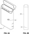
- FIGS. 4A and 4B illustrate examples, not according to the invention, that are useful for the understanding the disclosure where a pack 402 comprises a charging coil 403 with a large enough space in the center of the coil such that the charging coil 403 can surround an outer circumference of an eCig 400 placed within the pack 402.
- the eCig 400 can also comprise a receiving coil 401.
- the receiving coil 401 can be placed on an end of the eCig 400 and configured such that the eCig 400 can be placed within the pack 402 and the charging coil will surround the eCig 400 and the receiving coil 401. This can allow for the eCig 400 to be recharged while resting within the pack 402 without relying on any type of direct electrical connection.
- FIGS. 4A and 4B could also be present in a docking station or other charging stations.
- a recharging system that like described herein would keep the electrical system of the eCig 400 and the pack 402 free from exposure to elements that may corrode or otherwise degrade the performance of the eCig 400 and the pack 402.
- the pack 402 can comprise multiple charging coils 403 and can be configured to charge multiple eCigs 400 at one time.
- a "computer,” as used in this disclosure, means any machine, device, circuit, component, or module, or any system of machines, devices, circuits, components, modules, or the like, which are capable of manipulating data according to one or more instructions, such as, for example, without limitation, a processor, a microprocessor, a central processing unit, a general purpose computer, a super computer, a personal computer, a laptop computer, a palmtop computer, a notebook computer, a desktop computer, a workstation computer, a server, or the like, or an array of processors, microprocessors, central processing units, general purpose computers, super computers, personal computers, laptop computers, palmtop computers, notebook computers, desktop computers, workstation computers, servers, or the like.
- a "server,” as used in this disclosure, means any combination of software and/or hardware, including at least one application and/or at least one computer to perform services for connected clients as part of a client-server architecture.
- the at least one server application may include, but is not limited to, for example, an application program that can accept connections to service requests from clients by sending back responses to the clients.
- the server may be configured to run the at least one application, often under heavy workloads, unattended, for extended periods of time with minimal human direction.
- the server may include a plurality of computers configured, with the at least one application being divided among the computers depending upon the workload. For example, under light loading, the at least one application can run on a single computer. However, under heavy loading, multiple computers may be required to run the at least one application.
- the server, or any if its computers, may also be used as a workstation.
- a “network,” as used in this disclosure means, but is not limited to, for example, at least one of a local area network (LAN), a wide area network (WAN), a metropolitan area network (MAN), a personal area network (PAN), a campus area network, a corporate area network, a global area network (GAN), a broadband area network (BAN), a cellular network, the Internet, or the like, or any combination of the foregoing, any of which may be configured to communicate data via a wireless and/or a wired communication medium.
- These networks may run a variety of protocols not limited to TCP/IP, IRC or HTTP.
- sequences of instruction may be delivered from a RAM to a processor, (ii) may be carried over a wireless transmission medium, and/or (iii) may be formatted according to numerous formats, standards or protocols, including, for example, WiFi, WiMAX, IEEE 802.11, DECT, 0G, 1G, 2G, 3G or 4G cellular standards, Bluetooth, or the like.
- Devices that are in communication with each other need not be in continuous communication with each other, unless expressly specified otherwise.
- devices that are in communication with each other may communicate directly or indirectly through one or more intermediaries.
Landscapes
- Engineering & Computer Science (AREA)
- Power Engineering (AREA)
- Computer Networks & Wireless Communication (AREA)
- Charge And Discharge Circuits For Batteries Or The Like (AREA)
Priority Applications (2)
| Application Number | Priority Date | Filing Date | Title |
|---|---|---|---|
| PL15792522T PL3143676T3 (pl) | 2014-05-13 | 2015-05-13 | Sposób, system i urządzenie do indukcyjnego ładowania akumulatorów w papierosach elektronicznych |
| EP19171946.7A EP3557719B1 (en) | 2014-05-13 | 2015-05-13 | System for inductively charging batteries in electronic cigarettes |
Applications Claiming Priority (2)
| Application Number | Priority Date | Filing Date | Title |
|---|---|---|---|
| US201461992697P | 2014-05-13 | 2014-05-13 | |
| PCT/US2015/030655 WO2015175715A1 (en) | 2014-05-13 | 2015-05-13 | Method, system and device for inductively charging batteries in electronic cigarettes |
Related Child Applications (1)
| Application Number | Title | Priority Date | Filing Date |
|---|---|---|---|
| EP19171946.7A Division EP3557719B1 (en) | 2014-05-13 | 2015-05-13 | System for inductively charging batteries in electronic cigarettes |
Publications (3)
| Publication Number | Publication Date |
|---|---|
| EP3143676A1 EP3143676A1 (en) | 2017-03-22 |
| EP3143676A4 EP3143676A4 (en) | 2018-01-03 |
| EP3143676B1 true EP3143676B1 (en) | 2019-05-01 |
Family
ID=54480641
Family Applications (2)
| Application Number | Title | Priority Date | Filing Date |
|---|---|---|---|
| EP15792522.3A Active EP3143676B1 (en) | 2014-05-13 | 2015-05-13 | Method, system and device for inductively charging batteries in electronic cigarettes |
| EP19171946.7A Active EP3557719B1 (en) | 2014-05-13 | 2015-05-13 | System for inductively charging batteries in electronic cigarettes |
Family Applications After (1)
| Application Number | Title | Priority Date | Filing Date |
|---|---|---|---|
| EP19171946.7A Active EP3557719B1 (en) | 2014-05-13 | 2015-05-13 | System for inductively charging batteries in electronic cigarettes |
Country Status (6)
| Country | Link |
|---|---|
| US (2) | US10651684B2 (pl) |
| EP (2) | EP3143676B1 (pl) |
| CN (1) | CN106463980A (pl) |
| ES (1) | ES2927908T3 (pl) |
| PL (2) | PL3143676T3 (pl) |
| WO (1) | WO2015175715A1 (pl) |
Cited By (1)
| Publication number | Priority date | Publication date | Assignee | Title |
|---|---|---|---|---|
| RU2826514C2 (ru) * | 2021-06-11 | 2024-09-11 | Никовенчерс Трейдинг Лимитед | Устройство с зарядными площадками |
Families Citing this family (70)
| Publication number | Priority date | Publication date | Assignee | Title |
|---|---|---|---|---|
| US10244793B2 (en) | 2005-07-19 | 2019-04-02 | Juul Labs, Inc. | Devices for vaporization of a substance |
| GB2504076A (en) | 2012-07-16 | 2014-01-22 | Nicoventures Holdings Ltd | Electronic smoking device |
| GB2504075A (en) | 2012-07-16 | 2014-01-22 | Nicoventures Holdings Ltd | Electronic smoking device |
| US10279934B2 (en) | 2013-03-15 | 2019-05-07 | Juul Labs, Inc. | Fillable vaporizer cartridge and method of filling |
| US10039321B2 (en) | 2013-11-12 | 2018-08-07 | Vmr Products Llc | Vaporizer |
| US10159282B2 (en) | 2013-12-23 | 2018-12-25 | Juul Labs, Inc. | Cartridge for use with a vaporizer device |
| US10076139B2 (en) | 2013-12-23 | 2018-09-18 | Juul Labs, Inc. | Vaporizer apparatus |
| US10058129B2 (en) | 2013-12-23 | 2018-08-28 | Juul Labs, Inc. | Vaporization device systems and methods |
| DE202014011261U1 (de) | 2013-12-23 | 2018-11-13 | Juul Labs Uk Holdco Limited | Systeme für eine Verdampfungsvorrichtung |
| USD825102S1 (en) | 2016-07-28 | 2018-08-07 | Juul Labs, Inc. | Vaporizer device with cartridge |
| US20160366947A1 (en) | 2013-12-23 | 2016-12-22 | James Monsees | Vaporizer apparatus |
| USD842536S1 (en) | 2016-07-28 | 2019-03-05 | Juul Labs, Inc. | Vaporizer cartridge |
| US20160345628A1 (en) * | 2014-02-24 | 2016-12-01 | Arash Abdollahi Sabet | Electronic cigarette and cigar charging and operating systems integration with various cell phone and tablet types using a common case |
| WO2015131401A1 (zh) * | 2014-03-07 | 2015-09-11 | 吉瑞高新科技股份有限公司 | 具有清除积油功能的电子烟以及清除电子烟积油的方法 |
| EP3171720B1 (en) | 2014-07-24 | 2018-10-24 | Nicoventures Holdings Limited | Re-charging pack for an e-cigarette |
| GB2524735B (en) | 2014-03-31 | 2017-10-25 | Nicoventures Holdings Ltd | Re-charging pack for an e-cigarette |
| GB2524736B (en) * | 2014-03-31 | 2021-02-24 | Nicoventures Holdings Ltd | Re-charging pack for an e-cigarette |
| PL3143676T3 (pl) * | 2014-05-13 | 2019-12-31 | Fontem Holdings 4 B.V. | Sposób, system i urządzenie do indukcyjnego ładowania akumulatorów w papierosach elektronicznych |
| GB2528710B (en) * | 2014-07-24 | 2018-12-26 | Nicoventures Holdings Ltd | E-cigarette re-charging system |
| GB2559281B (en) | 2014-07-29 | 2019-05-15 | Nicoventures Holdings Ltd | E-cigarette and re-charging pack |
| CA160775S (en) | 2014-08-11 | 2015-09-29 | Ploom Inc | Electronic vaporization device with cartridge |
| WO2016075747A1 (ja) * | 2014-11-10 | 2016-05-19 | 日本たばこ産業株式会社 | 非燃焼型香味吸引器及びパッケージ |
| EP3217815B1 (en) * | 2014-11-14 | 2020-01-01 | JT International SA | Container for an aerosol generating device |
| EP3821735B1 (en) | 2014-12-05 | 2024-11-20 | Juul Labs, Inc. | Calibrated dose control |
| US10027016B2 (en) * | 2015-03-04 | 2018-07-17 | Rai Strategic Holdings Inc. | Antenna for an aerosol delivery device |
| US20160261020A1 (en) * | 2015-03-04 | 2016-09-08 | R.J. Reynolds Tobacco Company | Antenna for an Aerosol Delivery Device |
| GB201505595D0 (en) | 2015-03-31 | 2015-05-13 | British American Tobacco Co | Cartridge for use with apparatus for heating smokeable material |
| GB201505593D0 (en) | 2015-03-31 | 2015-05-13 | British American Tobacco Co | Article for use with apparatus for heating smokable material |
| GB201505597D0 (en) | 2015-03-31 | 2015-05-13 | British American Tobacco Co | Article for use with apparatus for heating smokable material |
| WO2017083541A1 (en) | 2015-11-10 | 2017-05-18 | Avanzato Technology Corp. | A disposable tank and mod assembly |
| EP3399876B2 (en) | 2016-01-07 | 2026-03-04 | Philip Morris Products S.A. | Aerosol-generating device with sealed compartment |
| US10258086B2 (en) * | 2016-01-12 | 2019-04-16 | Rai Strategic Holdings, Inc. | Hall effect current sensor for an aerosol delivery device |
| EA039727B1 (ru) | 2016-02-11 | 2022-03-04 | Джуул Лэбз, Инк. | Надежно прикрепляющиеся картриджи для испарительных устройств |
| EP3413960B1 (en) | 2016-02-11 | 2021-03-31 | Juul Labs, Inc. | Fillable vaporizer cartridge and method of filling |
| US10405582B2 (en) | 2016-03-10 | 2019-09-10 | Pax Labs, Inc. | Vaporization device with lip sensing |
| USD849996S1 (en) | 2016-06-16 | 2019-05-28 | Pax Labs, Inc. | Vaporizer cartridge |
| USD836541S1 (en) | 2016-06-23 | 2018-12-25 | Pax Labs, Inc. | Charging device |
| USD848057S1 (en) | 2016-06-23 | 2019-05-07 | Pax Labs, Inc. | Lid for a vaporizer |
| USD851830S1 (en) | 2016-06-23 | 2019-06-18 | Pax Labs, Inc. | Combined vaporizer tamp and pick tool |
| US10383367B2 (en) * | 2016-07-25 | 2019-08-20 | Fontem Holdings 1 B.V. | Electronic cigarette power supply portion |
| CN115736391B (zh) | 2016-08-05 | 2025-06-20 | 尤尔实验室有限公司 | 蒸发器的风速辅助控制 |
| MX2019002117A (es) | 2016-08-31 | 2019-07-08 | Philip Morris Products Sa | Sistema de carga inalambrica para cargar una fuente de energia electrica recargable de un dispositivo de calentamiento para articulos generadores de aerosol. |
| CN110191735A (zh) | 2016-12-12 | 2019-08-30 | Vmr产品有限责任公司 | 蒸发器 |
| USD887632S1 (en) | 2017-09-14 | 2020-06-16 | Pax Labs, Inc. | Vaporizer cartridge |
| USD889035S1 (en) | 2018-01-26 | 2020-06-30 | Juul Labs, Inc. | Case |
| USD889739S1 (en) | 2018-07-12 | 2020-07-07 | Juul Labs, Inc. | Case |
| US11196274B2 (en) | 2018-01-26 | 2021-12-07 | Juul Labs, Inc. | Charging case assembly |
| USD860523S1 (en) | 2018-02-28 | 2019-09-17 | Juul Labs, Inc. | Case |
| JP1710794S (ja) | 2018-02-28 | 2022-03-25 | 気化器用のケース | |
| US11638443B2 (en) | 2018-05-29 | 2023-05-02 | Juul Labs, Inc. | Heater control circuitry for vaporizer device |
| CN209807128U (zh) * | 2018-07-05 | 2019-12-20 | 深圳市艾维普思科技有限公司 | 电子烟的供电组件及电子烟 |
| US11103013B2 (en) | 2018-09-07 | 2021-08-31 | Fontem Holdings 1 B.V. | Pivotable charging case for electronic smoking device |
| US12543799B2 (en) | 2018-11-02 | 2026-02-10 | Juul Labs, Inc. | Vaporizer device with charging and reverse-charging capability |
| US10531693B1 (en) | 2019-02-14 | 2020-01-14 | Glas, Inc. | Vaporization device having remotely controllable operational modes |
| USD870374S1 (en) | 2019-02-14 | 2019-12-17 | Glas, Inc. | Mouthpiece of a cartridge for use with a vaporization device |
| USD1083619S1 (en) | 2019-02-14 | 2025-07-15 | Glas, Inc. | Packaging for cartridges for use with a vaporization device |
| EP3711516A1 (en) * | 2019-03-22 | 2020-09-23 | Nerudia Limited | Smoking substitute system |
| US12501942B2 (en) | 2019-03-22 | 2025-12-23 | Imperial Tobacco Limited | Smoking substitute system |
| CA187269S (en) * | 2019-04-25 | 2021-01-29 | Nguyen Tommy | Vape device |
| CN111602862A (zh) * | 2019-07-22 | 2020-09-01 | 深圳市艾维普思科技有限公司 | 电子烟的供电组件及电子烟 |
| JP6957577B2 (ja) * | 2019-11-05 | 2021-11-02 | 日本たばこ産業株式会社 | エアロゾル吸引器用の電源ユニット |
| JP6868077B1 (ja) | 2019-11-05 | 2021-05-12 | 日本たばこ産業株式会社 | エアロゾル吸引器用の電源ユニット、エアロゾル吸引器、及びエアロゾル吸引器用の充電ユニット |
| JP6706712B1 (ja) | 2019-11-05 | 2020-06-10 | 日本たばこ産業株式会社 | エアロゾル吸引器用の電源ユニット |
| JP6682033B1 (ja) * | 2019-11-05 | 2020-04-15 | 日本たばこ産業株式会社 | エアロゾル吸引器用の電源ユニット |
| WO2021176394A1 (en) * | 2020-03-06 | 2021-09-10 | Jt International Sa | Safety means and methods for vapor generating devices |
| GB202008076D0 (en) * | 2020-05-29 | 2020-07-15 | Nicoventures Trading Ltd | Aerosol provision device |
| KR102534235B1 (ko) * | 2020-07-07 | 2023-05-18 | 주식회사 케이티앤지 | 에어로졸 생성 장치 |
| GB202014516D0 (en) * | 2020-09-15 | 2020-10-28 | Nicoventures Trading Ltd | Aerosol generation system |
| GB202014520D0 (en) * | 2020-09-15 | 2020-10-28 | Nicoventures Trading Ltd | Aerosol generation system |
| US12438383B2 (en) | 2022-09-19 | 2025-10-07 | Altria Client Services Llc | Charging systems for aerosol-generating devices |
Family Cites Families (16)
| Publication number | Priority date | Publication date | Assignee | Title |
|---|---|---|---|---|
| KR100792311B1 (ko) | 2005-07-30 | 2008-01-07 | 엘에스전선 주식회사 | 충전전력 공급장치, 충전 장치, 배터리 장치, 무접점 충전 시스템 및 무접점 충전 방법 |
| US7948208B2 (en) * | 2006-06-01 | 2011-05-24 | Mojo Mobility, Inc. | Power source, charging system, and inductive receiver for mobile devices |
| JP2008301645A (ja) * | 2007-06-01 | 2008-12-11 | Sanyo Electric Co Ltd | 非接触式受電装置及びこれを具えた電子機器 |
| CN201094280Y (zh) * | 2007-08-23 | 2008-08-06 | 北京格林世界科技发展有限公司 | 电子香烟盒 |
| WO2010096917A1 (en) * | 2009-02-26 | 2010-09-02 | The University Of British Columbia | Systems and methods for dipole enhanced inductive power transfer |
| NL1037319C2 (nl) | 2009-09-25 | 2011-03-28 | Amidon B V | Apparaat voor het reinigen van bolvormige objecten. |
| US20110215755A1 (en) * | 2010-03-02 | 2011-09-08 | Sony Corporation | Insulated charging mat for consumer electronics (ce) device |
| PL2563172T5 (pl) | 2010-04-30 | 2022-08-29 | Fontem Holdings 4 B.V. | Urządzenie elektroniczne do palenia |
| US8928277B2 (en) * | 2011-01-28 | 2015-01-06 | Kimree Hi-Tech Inc | Electronic cigarette and a wireless charging device for the same |
| CN102884710B (zh) * | 2011-01-28 | 2015-11-25 | 惠州市吉瑞科技有限公司 | 一种无线充电装置 |
| EP2573900A1 (en) * | 2011-09-22 | 2013-03-27 | Da Ros, Daniele | Portable charger for electronic devices and corresponding charging method |
| WO2013185358A1 (zh) | 2012-06-16 | 2013-12-19 | Liu Qiuming | 电子烟盒及其电子烟装置 |
| US20140020697A1 (en) * | 2012-07-23 | 2014-01-23 | Qiuming Liu | Electronic Cigarette Case and Electronic Cigarette Device |
| WO2014125479A1 (en) * | 2013-02-12 | 2014-08-21 | Sis Resources Ltd. | Inductive charging for an electronic cigarette |
| EP3171720B1 (en) | 2014-07-24 | 2018-10-24 | Nicoventures Holdings Limited | Re-charging pack for an e-cigarette |
| PL3143676T3 (pl) * | 2014-05-13 | 2019-12-31 | Fontem Holdings 4 B.V. | Sposób, system i urządzenie do indukcyjnego ładowania akumulatorów w papierosach elektronicznych |
-
2015
- 2015-05-13 PL PL15792522T patent/PL3143676T3/pl unknown
- 2015-05-13 US US14/711,698 patent/US10651684B2/en active Active
- 2015-05-13 WO PCT/US2015/030655 patent/WO2015175715A1/en not_active Ceased
- 2015-05-13 EP EP15792522.3A patent/EP3143676B1/en active Active
- 2015-05-13 PL PL19171946.7T patent/PL3557719T3/pl unknown
- 2015-05-13 ES ES19171946T patent/ES2927908T3/es active Active
- 2015-05-13 EP EP19171946.7A patent/EP3557719B1/en active Active
- 2015-05-13 CN CN201580025049.5A patent/CN106463980A/zh active Pending
-
2020
- 2020-05-11 US US16/872,185 patent/US20200343767A1/en not_active Abandoned
Non-Patent Citations (1)
| Title |
|---|
| None * |
Cited By (1)
| Publication number | Priority date | Publication date | Assignee | Title |
|---|---|---|---|---|
| RU2826514C2 (ru) * | 2021-06-11 | 2024-09-11 | Никовенчерс Трейдинг Лимитед | Устройство с зарядными площадками |
Also Published As
| Publication number | Publication date |
|---|---|
| PL3143676T3 (pl) | 2019-12-31 |
| US20200343767A1 (en) | 2020-10-29 |
| EP3557719A1 (en) | 2019-10-23 |
| US10651684B2 (en) | 2020-05-12 |
| CN106463980A (zh) | 2017-02-22 |
| US20150333561A1 (en) | 2015-11-19 |
| EP3143676A1 (en) | 2017-03-22 |
| ES2927908T3 (es) | 2022-11-11 |
| EP3143676A4 (en) | 2018-01-03 |
| WO2015175715A1 (en) | 2015-11-19 |
| EP3557719B1 (en) | 2022-06-29 |
| PL3557719T3 (pl) | 2022-11-21 |
Similar Documents
| Publication | Publication Date | Title |
|---|---|---|
| EP3143676B1 (en) | Method, system and device for inductively charging batteries in electronic cigarettes | |
| US10873189B2 (en) | Method, system and device for controlling charging of batteries in electronic cigarettes | |
| US12349238B2 (en) | Method, system and device for controlling a heating element | |
| US11406139B2 (en) | Charging pack for an electronic smoking device | |
| US20260013573A1 (en) | Aerosol generation system | |
| KR20250088651A (ko) | 기화기 디바이스 히터 제어부 |
Legal Events
| Date | Code | Title | Description |
|---|---|---|---|
| STAA | Information on the status of an ep patent application or granted ep patent |
Free format text: STATUS: THE INTERNATIONAL PUBLICATION HAS BEEN MADE |
|
| PUAI | Public reference made under article 153(3) epc to a published international application that has entered the european phase |
Free format text: ORIGINAL CODE: 0009012 |
|
| STAA | Information on the status of an ep patent application or granted ep patent |
Free format text: STATUS: REQUEST FOR EXAMINATION WAS MADE |
|
| 17P | Request for examination filed |
Effective date: 20161206 |
|
| AK | Designated contracting states |
Kind code of ref document: A1 Designated state(s): AL AT BE BG CH CY CZ DE DK EE ES FI FR GB GR HR HU IE IS IT LI LT LU LV MC MK MT NL NO PL PT RO RS SE SI SK SM TR |
|
| AX | Request for extension of the european patent |
Extension state: BA ME |
|
| DAV | Request for validation of the european patent (deleted) | ||
| DAX | Request for extension of the european patent (deleted) | ||
| A4 | Supplementary search report drawn up and despatched |
Effective date: 20171204 |
|
| RIC1 | Information provided on ipc code assigned before grant |
Ipc: A24F 47/00 20060101ALI20171128BHEP Ipc: H02J 50/10 20160101ALI20171128BHEP Ipc: H02J 7/02 20160101ALI20171128BHEP Ipc: H02J 50/40 20160101ALI20171128BHEP Ipc: H02J 7/00 20060101AFI20171128BHEP |
|
| RIC1 | Information provided on ipc code assigned before grant |
Ipc: A24F 47/00 20060101ALI20181010BHEP Ipc: H02J 7/00 20060101AFI20181010BHEP Ipc: H02J 50/40 20160101ALI20181010BHEP Ipc: H02J 7/02 20160101ALI20181010BHEP Ipc: H02J 50/10 20160101ALI20181010BHEP |
|
| GRAP | Despatch of communication of intention to grant a patent |
Free format text: ORIGINAL CODE: EPIDOSNIGR1 |
|
| STAA | Information on the status of an ep patent application or granted ep patent |
Free format text: STATUS: GRANT OF PATENT IS INTENDED |
|
| INTG | Intention to grant announced |
Effective date: 20181122 |
|
| GRAS | Grant fee paid |
Free format text: ORIGINAL CODE: EPIDOSNIGR3 |
|
| GRAA | (expected) grant |
Free format text: ORIGINAL CODE: 0009210 |
|
| STAA | Information on the status of an ep patent application or granted ep patent |
Free format text: STATUS: THE PATENT HAS BEEN GRANTED |
|
| AK | Designated contracting states |
Kind code of ref document: B1 Designated state(s): AL AT BE BG CH CY CZ DE DK EE ES FI FR GB GR HR HU IE IS IT LI LT LU LV MC MK MT NL NO PL PT RO RS SE SI SK SM TR |
|
| REG | Reference to a national code |
Ref country code: GB Ref legal event code: FG4D |
|
| REG | Reference to a national code |
Ref country code: CH Ref legal event code: EP Ref country code: AT Ref legal event code: REF Ref document number: 1128207 Country of ref document: AT Kind code of ref document: T Effective date: 20190515 |
|
| REG | Reference to a national code |
Ref country code: DE Ref legal event code: R096 Ref document number: 602015029413 Country of ref document: DE |
|
| REG | Reference to a national code |
Ref country code: IE Ref legal event code: FG4D |
|
| REG | Reference to a national code |
Ref country code: NL Ref legal event code: FP |
|
| REG | Reference to a national code |
Ref country code: LT Ref legal event code: MG4D |
|
| PG25 | Lapsed in a contracting state [announced via postgrant information from national office to epo] |
Ref country code: SE Free format text: LAPSE BECAUSE OF FAILURE TO SUBMIT A TRANSLATION OF THE DESCRIPTION OR TO PAY THE FEE WITHIN THE PRESCRIBED TIME-LIMIT Effective date: 20190501 Ref country code: LT Free format text: LAPSE BECAUSE OF FAILURE TO SUBMIT A TRANSLATION OF THE DESCRIPTION OR TO PAY THE FEE WITHIN THE PRESCRIBED TIME-LIMIT Effective date: 20190501 Ref country code: FI Free format text: LAPSE BECAUSE OF FAILURE TO SUBMIT A TRANSLATION OF THE DESCRIPTION OR TO PAY THE FEE WITHIN THE PRESCRIBED TIME-LIMIT Effective date: 20190501 Ref country code: AL Free format text: LAPSE BECAUSE OF FAILURE TO SUBMIT A TRANSLATION OF THE DESCRIPTION OR TO PAY THE FEE WITHIN THE PRESCRIBED TIME-LIMIT Effective date: 20190501 Ref country code: PT Free format text: LAPSE BECAUSE OF FAILURE TO SUBMIT A TRANSLATION OF THE DESCRIPTION OR TO PAY THE FEE WITHIN THE PRESCRIBED TIME-LIMIT Effective date: 20190901 Ref country code: ES Free format text: LAPSE BECAUSE OF FAILURE TO SUBMIT A TRANSLATION OF THE DESCRIPTION OR TO PAY THE FEE WITHIN THE PRESCRIBED TIME-LIMIT Effective date: 20190501 Ref country code: NO Free format text: LAPSE BECAUSE OF FAILURE TO SUBMIT A TRANSLATION OF THE DESCRIPTION OR TO PAY THE FEE WITHIN THE PRESCRIBED TIME-LIMIT Effective date: 20190801 Ref country code: HR Free format text: LAPSE BECAUSE OF FAILURE TO SUBMIT A TRANSLATION OF THE DESCRIPTION OR TO PAY THE FEE WITHIN THE PRESCRIBED TIME-LIMIT Effective date: 20190501 |
|
| PG25 | Lapsed in a contracting state [announced via postgrant information from national office to epo] |
Ref country code: GR Free format text: LAPSE BECAUSE OF FAILURE TO SUBMIT A TRANSLATION OF THE DESCRIPTION OR TO PAY THE FEE WITHIN THE PRESCRIBED TIME-LIMIT Effective date: 20190802 Ref country code: BG Free format text: LAPSE BECAUSE OF FAILURE TO SUBMIT A TRANSLATION OF THE DESCRIPTION OR TO PAY THE FEE WITHIN THE PRESCRIBED TIME-LIMIT Effective date: 20190801 Ref country code: RS Free format text: LAPSE BECAUSE OF FAILURE TO SUBMIT A TRANSLATION OF THE DESCRIPTION OR TO PAY THE FEE WITHIN THE PRESCRIBED TIME-LIMIT Effective date: 20190501 Ref country code: LV Free format text: LAPSE BECAUSE OF FAILURE TO SUBMIT A TRANSLATION OF THE DESCRIPTION OR TO PAY THE FEE WITHIN THE PRESCRIBED TIME-LIMIT Effective date: 20190501 |
|
| REG | Reference to a national code |
Ref country code: AT Ref legal event code: MK05 Ref document number: 1128207 Country of ref document: AT Kind code of ref document: T Effective date: 20190501 |
|
| REG | Reference to a national code |
Ref country code: CH Ref legal event code: PL |
|
| PG25 | Lapsed in a contracting state [announced via postgrant information from national office to epo] |
Ref country code: IS Free format text: LAPSE BECAUSE OF FAILURE TO SUBMIT A TRANSLATION OF THE DESCRIPTION OR TO PAY THE FEE WITHIN THE PRESCRIBED TIME-LIMIT Effective date: 20190901 |
|
| PG25 | Lapsed in a contracting state [announced via postgrant information from national office to epo] |
Ref country code: EE Free format text: LAPSE BECAUSE OF FAILURE TO SUBMIT A TRANSLATION OF THE DESCRIPTION OR TO PAY THE FEE WITHIN THE PRESCRIBED TIME-LIMIT Effective date: 20190501 Ref country code: AT Free format text: LAPSE BECAUSE OF FAILURE TO SUBMIT A TRANSLATION OF THE DESCRIPTION OR TO PAY THE FEE WITHIN THE PRESCRIBED TIME-LIMIT Effective date: 20190501 Ref country code: DK Free format text: LAPSE BECAUSE OF FAILURE TO SUBMIT A TRANSLATION OF THE DESCRIPTION OR TO PAY THE FEE WITHIN THE PRESCRIBED TIME-LIMIT Effective date: 20190501 Ref country code: RO Free format text: LAPSE BECAUSE OF FAILURE TO SUBMIT A TRANSLATION OF THE DESCRIPTION OR TO PAY THE FEE WITHIN THE PRESCRIBED TIME-LIMIT Effective date: 20190501 Ref country code: CZ Free format text: LAPSE BECAUSE OF FAILURE TO SUBMIT A TRANSLATION OF THE DESCRIPTION OR TO PAY THE FEE WITHIN THE PRESCRIBED TIME-LIMIT Effective date: 20190501 Ref country code: CH Free format text: LAPSE BECAUSE OF NON-PAYMENT OF DUE FEES Effective date: 20190531 Ref country code: MC Free format text: LAPSE BECAUSE OF FAILURE TO SUBMIT A TRANSLATION OF THE DESCRIPTION OR TO PAY THE FEE WITHIN THE PRESCRIBED TIME-LIMIT Effective date: 20190501 Ref country code: SK Free format text: LAPSE BECAUSE OF FAILURE TO SUBMIT A TRANSLATION OF THE DESCRIPTION OR TO PAY THE FEE WITHIN THE PRESCRIBED TIME-LIMIT Effective date: 20190501 Ref country code: LI Free format text: LAPSE BECAUSE OF NON-PAYMENT OF DUE FEES Effective date: 20190531 |
|
| REG | Reference to a national code |
Ref country code: DE Ref legal event code: R097 Ref document number: 602015029413 Country of ref document: DE |
|
| REG | Reference to a national code |
Ref country code: BE Ref legal event code: MM Effective date: 20190531 |
|
| PG25 | Lapsed in a contracting state [announced via postgrant information from national office to epo] |
Ref country code: SM Free format text: LAPSE BECAUSE OF FAILURE TO SUBMIT A TRANSLATION OF THE DESCRIPTION OR TO PAY THE FEE WITHIN THE PRESCRIBED TIME-LIMIT Effective date: 20190501 Ref country code: LU Free format text: LAPSE BECAUSE OF NON-PAYMENT OF DUE FEES Effective date: 20190513 |
|
| PLBE | No opposition filed within time limit |
Free format text: ORIGINAL CODE: 0009261 |
|
| STAA | Information on the status of an ep patent application or granted ep patent |
Free format text: STATUS: NO OPPOSITION FILED WITHIN TIME LIMIT |
|
| PG25 | Lapsed in a contracting state [announced via postgrant information from national office to epo] |
Ref country code: TR Free format text: LAPSE BECAUSE OF FAILURE TO SUBMIT A TRANSLATION OF THE DESCRIPTION OR TO PAY THE FEE WITHIN THE PRESCRIBED TIME-LIMIT Effective date: 20190501 |
|
| 26N | No opposition filed |
Effective date: 20200204 |
|
| PG25 | Lapsed in a contracting state [announced via postgrant information from national office to epo] |
Ref country code: IE Free format text: LAPSE BECAUSE OF NON-PAYMENT OF DUE FEES Effective date: 20190513 |
|
| PG25 | Lapsed in a contracting state [announced via postgrant information from national office to epo] |
Ref country code: BE Free format text: LAPSE BECAUSE OF NON-PAYMENT OF DUE FEES Effective date: 20190531 Ref country code: SI Free format text: LAPSE BECAUSE OF FAILURE TO SUBMIT A TRANSLATION OF THE DESCRIPTION OR TO PAY THE FEE WITHIN THE PRESCRIBED TIME-LIMIT Effective date: 20190501 |
|
| PG25 | Lapsed in a contracting state [announced via postgrant information from national office to epo] |
Ref country code: CY Free format text: LAPSE BECAUSE OF FAILURE TO SUBMIT A TRANSLATION OF THE DESCRIPTION OR TO PAY THE FEE WITHIN THE PRESCRIBED TIME-LIMIT Effective date: 20190501 |
|
| PG25 | Lapsed in a contracting state [announced via postgrant information from national office to epo] |
Ref country code: MT Free format text: LAPSE BECAUSE OF FAILURE TO SUBMIT A TRANSLATION OF THE DESCRIPTION OR TO PAY THE FEE WITHIN THE PRESCRIBED TIME-LIMIT Effective date: 20190501 Ref country code: HU Free format text: LAPSE BECAUSE OF FAILURE TO SUBMIT A TRANSLATION OF THE DESCRIPTION OR TO PAY THE FEE WITHIN THE PRESCRIBED TIME-LIMIT; INVALID AB INITIO Effective date: 20150513 |
|
| PG25 | Lapsed in a contracting state [announced via postgrant information from national office to epo] |
Ref country code: MK Free format text: LAPSE BECAUSE OF FAILURE TO SUBMIT A TRANSLATION OF THE DESCRIPTION OR TO PAY THE FEE WITHIN THE PRESCRIBED TIME-LIMIT Effective date: 20190501 |
|
| P01 | Opt-out of the competence of the unified patent court (upc) registered |
Effective date: 20230517 |
|
| REG | Reference to a national code |
Ref country code: DE Ref legal event code: R081 Ref document number: 602015029413 Country of ref document: DE Owner name: FONTEM VENTURES B.V., NL Free format text: FORMER OWNER: FONTEM HOLDINGS 4 B.V., AMSTERDAM, NL |
|
| REG | Reference to a national code |
Ref country code: NL Ref legal event code: PD Owner name: FONTEM VENTURES B.V.; NL Free format text: DETAILS ASSIGNMENT: CHANGE OF OWNER(S), MERGE; FORMER OWNER NAME: FONTEM HOLDINGS B.V. Effective date: 20231002 |
|
| REG | Reference to a national code |
Ref country code: GB Ref legal event code: 732E Free format text: REGISTERED BETWEEN 20231214 AND 20231220 |
|
| PGFP | Annual fee paid to national office [announced via postgrant information from national office to epo] |
Ref country code: NL Payment date: 20250423 Year of fee payment: 11 |
|
| PGFP | Annual fee paid to national office [announced via postgrant information from national office to epo] |
Ref country code: DE Payment date: 20250423 Year of fee payment: 11 |
|
| PGFP | Annual fee paid to national office [announced via postgrant information from national office to epo] |
Ref country code: GB Payment date: 20250423 Year of fee payment: 11 |
|
| PGFP | Annual fee paid to national office [announced via postgrant information from national office to epo] |
Ref country code: IT Payment date: 20250423 Year of fee payment: 11 |
|
| PGFP | Annual fee paid to national office [announced via postgrant information from national office to epo] |
Ref country code: FR Payment date: 20250423 Year of fee payment: 11 |
|
| PGFP | Annual fee paid to national office [announced via postgrant information from national office to epo] |
Ref country code: PL Payment date: 20250423 Year of fee payment: 11 |