EP3143965A1 - Stosskörpervorrichtung, genannt impinger, zum ausführen eines stosses auf eine stange - Google Patents
Stosskörpervorrichtung, genannt impinger, zum ausführen eines stosses auf eine stange Download PDFInfo
- Publication number
- EP3143965A1 EP3143965A1 EP16186875.7A EP16186875A EP3143965A1 EP 3143965 A1 EP3143965 A1 EP 3143965A1 EP 16186875 A EP16186875 A EP 16186875A EP 3143965 A1 EP3143965 A1 EP 3143965A1
- Authority
- EP
- European Patent Office
- Prior art keywords
- rod
- shock
- slide
- barrel
- insert
- Prior art date
- Legal status (The legal status is an assumption and is not a legal conclusion. Google has not performed a legal analysis and makes no representation as to the accuracy of the status listed.)
- Granted
Links
Images


Classifications
-
- A—HUMAN NECESSITIES
- A61—MEDICAL OR VETERINARY SCIENCE; HYGIENE
- A61F—FILTERS IMPLANTABLE INTO BLOOD VESSELS; PROSTHESES; DEVICES PROVIDING PATENCY TO, OR PREVENTING COLLAPSING OF, TUBULAR STRUCTURES OF THE BODY, e.g. STENTS; ORTHOPAEDIC, NURSING OR CONTRACEPTIVE DEVICES; FOMENTATION; TREATMENT OR PROTECTION OF EYES OR EARS; BANDAGES, DRESSINGS OR ABSORBENT PADS; FIRST-AID KITS
- A61F2/00—Filters implantable into blood vessels; Prostheses, i.e. artificial substitutes or replacements for parts of the body; Appliances for connecting them with the body; Devices providing patency to, or preventing collapsing of, tubular structures of the body, e.g. stents
- A61F2/02—Prostheses implantable into the body
- A61F2/30—Joints
- A61F2/46—Special tools for implanting artificial joints
- A61F2/4603—Special tools for implanting artificial joints for insertion or extraction of endoprosthetic joints or of accessories thereof
- A61F2/4609—Special tools for implanting artificial joints for insertion or extraction of endoprosthetic joints or of accessories thereof of acetabular cups
-
- A—HUMAN NECESSITIES
- A61—MEDICAL OR VETERINARY SCIENCE; HYGIENE
- A61B—DIAGNOSIS; SURGERY; IDENTIFICATION
- A61B17/00—Surgical instruments, devices or methods
- A61B17/56—Surgical instruments or methods for treatment of bones or joints; Devices specially adapted therefor
- A61B17/58—Surgical instruments or methods for treatment of bones or joints; Devices specially adapted therefor for osteosynthesis, e.g. bone plates, screws or setting implements
- A61B17/88—Osteosynthesis instruments; Methods or means for implanting or extracting internal or external fixation devices
- A61B17/92—Impactors or extractors, e.g. for removing intramedullary devices
-
- A—HUMAN NECESSITIES
- A61—MEDICAL OR VETERINARY SCIENCE; HYGIENE
- A61B—DIAGNOSIS; SURGERY; IDENTIFICATION
- A61B90/00—Instruments, implements or accessories specially adapted for surgery or diagnosis and not covered by any of the groups A61B1/00 - A61B50/00, e.g. for luxation treatment or for protecting wound edges
- A61B90/03—Automatic limiting or abutting means, e.g. for safety
-
- A—HUMAN NECESSITIES
- A61—MEDICAL OR VETERINARY SCIENCE; HYGIENE
- A61F—FILTERS IMPLANTABLE INTO BLOOD VESSELS; PROSTHESES; DEVICES PROVIDING PATENCY TO, OR PREVENTING COLLAPSING OF, TUBULAR STRUCTURES OF THE BODY, e.g. STENTS; ORTHOPAEDIC, NURSING OR CONTRACEPTIVE DEVICES; FOMENTATION; TREATMENT OR PROTECTION OF EYES OR EARS; BANDAGES, DRESSINGS OR ABSORBENT PADS; FIRST-AID KITS
- A61F2/00—Filters implantable into blood vessels; Prostheses, i.e. artificial substitutes or replacements for parts of the body; Appliances for connecting them with the body; Devices providing patency to, or preventing collapsing of, tubular structures of the body, e.g. stents
- A61F2/02—Prostheses implantable into the body
- A61F2/30—Joints
- A61F2/32—Joints for the hip
- A61F2/34—Acetabular cups
-
- A—HUMAN NECESSITIES
- A61—MEDICAL OR VETERINARY SCIENCE; HYGIENE
- A61F—FILTERS IMPLANTABLE INTO BLOOD VESSELS; PROSTHESES; DEVICES PROVIDING PATENCY TO, OR PREVENTING COLLAPSING OF, TUBULAR STRUCTURES OF THE BODY, e.g. STENTS; ORTHOPAEDIC, NURSING OR CONTRACEPTIVE DEVICES; FOMENTATION; TREATMENT OR PROTECTION OF EYES OR EARS; BANDAGES, DRESSINGS OR ABSORBENT PADS; FIRST-AID KITS
- A61F2/00—Filters implantable into blood vessels; Prostheses, i.e. artificial substitutes or replacements for parts of the body; Appliances for connecting them with the body; Devices providing patency to, or preventing collapsing of, tubular structures of the body, e.g. stents
- A61F2/02—Prostheses implantable into the body
- A61F2/30—Joints
- A61F2/46—Special tools for implanting artificial joints
- A61F2/4637—Special tools for implanting artificial joints for connecting or disconnecting two parts of a prosthesis
-
- A—HUMAN NECESSITIES
- A61—MEDICAL OR VETERINARY SCIENCE; HYGIENE
- A61B—DIAGNOSIS; SURGERY; IDENTIFICATION
- A61B90/00—Instruments, implements or accessories specially adapted for surgery or diagnosis and not covered by any of the groups A61B1/00 - A61B50/00, e.g. for luxation treatment or for protecting wound edges
- A61B90/03—Automatic limiting or abutting means, e.g. for safety
- A61B2090/033—Abutting means, stops, e.g. abutting on tissue or skin
- A61B2090/034—Abutting means, stops, e.g. abutting on tissue or skin abutting on parts of the device itself
-
- A—HUMAN NECESSITIES
- A61—MEDICAL OR VETERINARY SCIENCE; HYGIENE
- A61F—FILTERS IMPLANTABLE INTO BLOOD VESSELS; PROSTHESES; DEVICES PROVIDING PATENCY TO, OR PREVENTING COLLAPSING OF, TUBULAR STRUCTURES OF THE BODY, e.g. STENTS; ORTHOPAEDIC, NURSING OR CONTRACEPTIVE DEVICES; FOMENTATION; TREATMENT OR PROTECTION OF EYES OR EARS; BANDAGES, DRESSINGS OR ABSORBENT PADS; FIRST-AID KITS
- A61F2/00—Filters implantable into blood vessels; Prostheses, i.e. artificial substitutes or replacements for parts of the body; Appliances for connecting them with the body; Devices providing patency to, or preventing collapsing of, tubular structures of the body, e.g. stents
- A61F2/02—Prostheses implantable into the body
- A61F2/30—Joints
- A61F2002/30001—Additional features of subject-matter classified in A61F2/28, A61F2/30 and subgroups thereof
- A61F2002/30316—The prosthesis having different structural features at different locations within the same prosthesis; Connections between prosthetic parts; Special structural features of bone or joint prostheses not otherwise provided for
- A61F2002/30535—Special structural features of bone or joint prostheses not otherwise provided for
- A61F2002/30558—Force-limiting means
-
- A—HUMAN NECESSITIES
- A61—MEDICAL OR VETERINARY SCIENCE; HYGIENE
- A61F—FILTERS IMPLANTABLE INTO BLOOD VESSELS; PROSTHESES; DEVICES PROVIDING PATENCY TO, OR PREVENTING COLLAPSING OF, TUBULAR STRUCTURES OF THE BODY, e.g. STENTS; ORTHOPAEDIC, NURSING OR CONTRACEPTIVE DEVICES; FOMENTATION; TREATMENT OR PROTECTION OF EYES OR EARS; BANDAGES, DRESSINGS OR ABSORBENT PADS; FIRST-AID KITS
- A61F2/00—Filters implantable into blood vessels; Prostheses, i.e. artificial substitutes or replacements for parts of the body; Appliances for connecting them with the body; Devices providing patency to, or preventing collapsing of, tubular structures of the body, e.g. stents
- A61F2/02—Prostheses implantable into the body
- A61F2/30—Joints
- A61F2002/30001—Additional features of subject-matter classified in A61F2/28, A61F2/30 and subgroups thereof
- A61F2002/30316—The prosthesis having different structural features at different locations within the same prosthesis; Connections between prosthetic parts; Special structural features of bone or joint prostheses not otherwise provided for
- A61F2002/30535—Special structural features of bone or joint prostheses not otherwise provided for
- A61F2002/30565—Special structural features of bone or joint prostheses not otherwise provided for having spring elements
- A61F2002/30566—Helical springs
-
- A—HUMAN NECESSITIES
- A61—MEDICAL OR VETERINARY SCIENCE; HYGIENE
- A61F—FILTERS IMPLANTABLE INTO BLOOD VESSELS; PROSTHESES; DEVICES PROVIDING PATENCY TO, OR PREVENTING COLLAPSING OF, TUBULAR STRUCTURES OF THE BODY, e.g. STENTS; ORTHOPAEDIC, NURSING OR CONTRACEPTIVE DEVICES; FOMENTATION; TREATMENT OR PROTECTION OF EYES OR EARS; BANDAGES, DRESSINGS OR ABSORBENT PADS; FIRST-AID KITS
- A61F2/00—Filters implantable into blood vessels; Prostheses, i.e. artificial substitutes or replacements for parts of the body; Appliances for connecting them with the body; Devices providing patency to, or preventing collapsing of, tubular structures of the body, e.g. stents
- A61F2/02—Prostheses implantable into the body
- A61F2/30—Joints
- A61F2/46—Special tools for implanting artificial joints
- A61F2/4603—Special tools for implanting artificial joints for insertion or extraction of endoprosthetic joints or of accessories thereof
- A61F2002/4625—Special tools for implanting artificial joints for insertion or extraction of endoprosthetic joints or of accessories thereof with relative movement between parts of the instrument during use
- A61F2002/4627—Special tools for implanting artificial joints for insertion or extraction of endoprosthetic joints or of accessories thereof with relative movement between parts of the instrument during use with linear motion along or rotating motion about the instrument axis or the implantation direction, e.g. telescopic, along a guiding rod, screwing inside the instrument
-
- A—HUMAN NECESSITIES
- A61—MEDICAL OR VETERINARY SCIENCE; HYGIENE
- A61F—FILTERS IMPLANTABLE INTO BLOOD VESSELS; PROSTHESES; DEVICES PROVIDING PATENCY TO, OR PREVENTING COLLAPSING OF, TUBULAR STRUCTURES OF THE BODY, e.g. STENTS; ORTHOPAEDIC, NURSING OR CONTRACEPTIVE DEVICES; FOMENTATION; TREATMENT OR PROTECTION OF EYES OR EARS; BANDAGES, DRESSINGS OR ABSORBENT PADS; FIRST-AID KITS
- A61F2/00—Filters implantable into blood vessels; Prostheses, i.e. artificial substitutes or replacements for parts of the body; Appliances for connecting them with the body; Devices providing patency to, or preventing collapsing of, tubular structures of the body, e.g. stents
- A61F2/02—Prostheses implantable into the body
- A61F2/30—Joints
- A61F2/46—Special tools for implanting artificial joints
- A61F2002/4681—Special tools for implanting artificial joints by applying mechanical shocks, e.g. by hammering
-
- A—HUMAN NECESSITIES
- A61—MEDICAL OR VETERINARY SCIENCE; HYGIENE
- A61F—FILTERS IMPLANTABLE INTO BLOOD VESSELS; PROSTHESES; DEVICES PROVIDING PATENCY TO, OR PREVENTING COLLAPSING OF, TUBULAR STRUCTURES OF THE BODY, e.g. STENTS; ORTHOPAEDIC, NURSING OR CONTRACEPTIVE DEVICES; FOMENTATION; TREATMENT OR PROTECTION OF EYES OR EARS; BANDAGES, DRESSINGS OR ABSORBENT PADS; FIRST-AID KITS
- A61F2310/00—Prostheses classified in A61F2/28 or A61F2/30 - A61F2/44 being constructed from or coated with a particular material
- A61F2310/00005—The prosthesis being constructed from a particular material
- A61F2310/00179—Ceramics or ceramic-like structures
Definitions
- the present invention relates to a so-called impactor device for imparting an impact to a rod, the rod having the function of transmitting this shock to an insert, for example a ceramic insert, to insert it into a receiving element, for example. for example a cup intended to be positioned in the acetabulum of a hip.
- the insert is grasped by means of a gripping device comprising a stem, positions the insert taken by the gripping device over the open cavity of the cup and, using an impactor device in the form of a hammer, the surgeon applies a shock to the rod to penetrate the insert in the cup.
- the present invention aims to overcome the drawbacks of the prior art by providing an impactor device which ensures the surgeon performing the impaction of an insert in a cup that, whatever its shape of the day, it applies the good shock value, and in the right direction of application, so that the insert is inserted properly into the cup, drastically reducing the number of times the surgeon has to go back several times or use a new insert-cup torque in replacement of the damaged insert-cup couple by a faulty first insertion attempt.
- an impactor device for imparting a shock to a rod, in particular independent of the device, the rod being itself coupled to an insert element intended to be inserted into a receiving element, in particular a ceramic insert in a cup of a hip acetabular cavity;
- the impactor device being as defined in claim 1.
- the means application shock give it the shock of a power as expected and in the exact direction, drastically reducing the applications with a shock of an erroneous and / or misaligned, in particular lower than the theoretical value supposed to be applied.
- This provides a particularly reliable system to ensure the surgeon a strike as accurate as possible of the rod and thus an insertion along the correct axis and with the good strength of the insert in the cup.
- the system according to the invention is particularly simple to use and in particular the cleaning of the system is facilitated by the fact that the rod is independent of the body of the device.
- the prestressing means are arranged to block the action of the impact application means on the rod as long as the user does not apply the impactor device against the rod with the minimum pressure determined in advance, the arrangement being such that when the minimum pressure determined in advance is applied the shock application means can be actuated by the triggering means.
- the prestressing means comprise a slider slidably mounted relative to the barrel element, the slider being mounted under the constraint of a spring tending to maintain the distal end of the slider at a distance. distal opening of the barrel.
- the slide cooperates with the trigger means so that it blocks any action trigger means, and when the gun is pressed against the slide, it releases the trigger means.
- the triggering means comprise a striker controlled by a trigger, the striker abutting against the slideway in the position in which it is not exerted pressure of the device against the rod with said minimum pressure determined in advance and being released by the slide when at least the minimum pressure determined in advance is exerted.
- latching means in particular in the form of a detent ball received in a bore perpendicular to the axis of the barrel and opening into the channel receiving the rod, and a bowl formed in the shaft, into which the ball penetrates, for partially limiting the relative displacement of the shaft between two proximal and distal end positions corresponding to the respective distal and proximal ends of the bowl, in the proximal position rod being exactly where it should be to be impacted as intended and in the distal position, the rod being set back from the large diameter channel.
- abutment means from the rod intended to abut against the edge of the distal opening of the slide.
- the present invention also relates to an assembly comprising an impactor device according to the invention and a rod that can be inserted into the receiving channel of the open rod at the distal end of the impactor device.
- the present invention also relates to an assembly comprising an assembly according to the invention and an insert coupled to the rod and a cup, in which the insert is intended to be impacted.
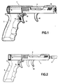
- an impactor device according to an embodiment of the invention an assembly comprising the impactor device and a rod inserted into the impactor device.
- the impinger device and a rod according to the invention are shown.
- the device 1 impactor has the general shape of a pistol.
- a rod 2 is inserted partially into the gun barrel 1.
- the gun-shaped impactor device has a main body having a pistol grip-shaped handle 3 and a substantially tubular barrel member 4 extending from the buttstock.
- the tubular barrel member 4 defines therein an inner channel 5 opening to a distal end opening 6 of the gun-shaped member, opening 6 through which the rod 2 penetrates.
- the inner channel 5 has a proximal section 7 of large cross-section and a smaller section of distal section 8 after the section 7 of large section, the two sections 7, 8 being separated by a shoulder 9.
- the small section of the section 8 is substantially equal to that of the portion of the rod 2 intended to be inserted into the gun and is smaller than the section of the section 7.
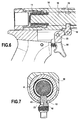
- a hammer 10 shaped cylindrical pusher substantially identical section to that of the section of large section which is mounted under the bias of a spring 11.
- the hammer 10 is held against the spring 11 in the compressed state by a lug tab 12 which penetrates into an annular groove 13 of the hammer.
- the lug forming the keeper 12 has a rod portion 42 extending perpendicularly to the barrel axis and a head portion 43 projecting laterally from the rod 42 to define a hooking zone, the function of which will be defined later. in the description in conjunction with a slide 16.
- a trigger 14 is pivotally mounted relative to the butt and is articulated to the rod 42 of the striker 12, so that when the user holds the device by the butt, it can press with a finger, including the index finger, on the trigger 14 to rotate it in the direction of the needles d a watch, at the figure 6 , with respect to its axis of rotation (axis perpendicular to the direction of the figure), this having the effect of causing the trigger 12 to move downwardly out of the groove 13 and release the hammer 10 towards the rod ( to the right at the figure 6 ) under the effect of the thrust of the spring 11 released.
- the hammer 10 can then strike the proximal end of the rod 2 inserted in the channel 8 and having partially penetrated into the channel 7 of large section.
- the pistol device comprises a tubular element forming a slide 16 which surrounds, to a large extent, the barrel 4.
- the slide 16 can slide relative to the barrel 4.
- the slide 16 has a distal opening 17 screwed vis-à-vis the distal opening 6 of the barrel 4 to allow the passage of the rod 2 within the channel 5 defined in the tubular element 4 forming the barrel.
- a helical slide spring 20 is mounted inside the slideway 16, between the slideway 16 and the barrel 4.
- the spring bears on the one hand against the distal lateral inner face 19 of the slide and against an annular abutment 21 formed at the outer face of the barrel 4, away from the distal opening 6.
- the spring is arranged to maintain elastically at a distance the distal lateral inner face 19 of the slide and the distal edge of the distal opening 6 of the barrel 4.
- the substantially cylindrical rod 2 is shown in detail, with respect to a proximal end section, at the Figure 5B .
- This proximal section has two flats 30 and 31 opposite left and right which have an extension in the longitudinal direction of the rod which is greater than the length extension of the small diameter section 8 of the channel 5.
- the shape of the cross section of the section 8 of the channel 5 corresponds to that of the flats section of the rod, so that when the part of the rod comprising the flats is introduced into the channel 5, this can only be done for a given relative orientation of the rod and of the barrel, the flats then preventing any rotation of the rod relative to the barrel.
- the rod has two stops 32 respectively at the end of the flats 30 and 31 left and right, so that the rod can not be introduced into the channel 5 further when these stops 32 abut against the outer edge of the distal opening of the slide 16.
- the rod also comprises two upper and lower cuvettes 34 formed in the lateral face of the rod 2 extending between the two flats.
- These two cuvettes can each receive a snap-action pusher ball spring-mounted so as to project partially inside the channel section 8.
- the pusher ball 35 is mounted in a bore 50 perpendicular to the axis of the barrel being under an elastic bias, for example a spring (not visible in the figures) which tends to maintain in part to the inside of the section 8 while being able, however, under a thrust action of the rod during its introduction into the channel, to be pushed inside the bore 50, to allow the passage of the rod, the ball pusher returning, after passage of the proximal portion without the bowl of the stem, in one of the two bowls, for example the upper bowl.
- an elastic bias for example a spring (not visible in the figures) which tends to maintain in part to the inside of the section 8 while being able, however, under a thrust action of the rod during its introduction into the channel, to be pushed inside the bore 50, to allow the passage of the rod, the ball pusher returning, after passage of the proximal portion without the bowl of the stem,
- the relative dimensions of the rod, in particular the flats 30 and 31, the stops 32, the cups 34, the ball 35, the section 8, the annular stop 21, the barrel and the slideway are chosen so that one part when the axial abutments 32 of the rod abuts against the outer edge of the distal opening of the slide 16 and the spring between the slide and the barrel is at rest, the proximal end of the rod does not exceed the section 8 and in particular does not enter the section 7 of large section and the ball 35 is partially received in the upper bowl 34 and abuts against the proximal edge of the upper bowl 34 and secondly when the spring is compressed by a action of the user pressing the device, in particular the slideway, against the rod so that there is contact between the distal inner face of the slide and the edge of the distal opening of the barrel, the push ball abuts against the edge distal of the bowl and the rod has penetrated into the channel 7 of large section, exactly in the right relative position relative to the hammer so that the shock is delivered as it should be.
- the substantially tubular slide 16 On the proximal side (see in particular the Figures 4a and 4b ) the substantially tubular slide 16 is open.
- the proximal lateral edge 23 of the slide is hooked by the head 43 of the striker 12, which annihilates any movement thereof, especially downward (upwards to the figure 3a ).
- the relative action of the pusher ball and the bowl performs a latching function which allows the user to be informed, when pressing the device against the rod, the position in which it is located, including the when the trigger was released.
- a tab 40 is integral with the slide 16 and assists the user in sliding the slideway, in particular against the tension of the spring 20.
- figure 2 the device is shown in the disarmed position or security. In dashed lines, it is represented the position in which the tab 40 is in the armed or unblocked position. In contrast, the slide, at the figure 2 , is only shown in the safety position.
Landscapes
- Health & Medical Sciences (AREA)
- Orthopedic Medicine & Surgery (AREA)
- Life Sciences & Earth Sciences (AREA)
- Transplantation (AREA)
- Animal Behavior & Ethology (AREA)
- General Health & Medical Sciences (AREA)
- Biomedical Technology (AREA)
- Heart & Thoracic Surgery (AREA)
- Veterinary Medicine (AREA)
- Engineering & Computer Science (AREA)
- Public Health (AREA)
- Oral & Maxillofacial Surgery (AREA)
- Surgery (AREA)
- Cardiology (AREA)
- Vascular Medicine (AREA)
- Physical Education & Sports Medicine (AREA)
- Nuclear Medicine, Radiotherapy & Molecular Imaging (AREA)
- Medical Informatics (AREA)
- Molecular Biology (AREA)
- Pathology (AREA)
- Prostheses (AREA)
Applications Claiming Priority (1)
| Application Number | Priority Date | Filing Date | Title |
|---|---|---|---|
| FR1501817A FR3040290B1 (fr) | 2015-09-02 | 2015-09-02 | Dispositif dit impacteur a impartir un choc a une tige |
Publications (2)
| Publication Number | Publication Date |
|---|---|
| EP3143965A1 true EP3143965A1 (de) | 2017-03-22 |
| EP3143965B1 EP3143965B1 (de) | 2020-02-26 |
Family
ID=54329586
Family Applications (1)
| Application Number | Title | Priority Date | Filing Date |
|---|---|---|---|
| EP16186875.7A Active EP3143965B1 (de) | 2015-09-02 | 2016-09-01 | Stosskörpervorrichtung zum ausführen eines stosses auf eine stange |
Country Status (3)
| Country | Link |
|---|---|
| US (1) | US10231848B2 (de) |
| EP (1) | EP3143965B1 (de) |
| FR (1) | FR3040290B1 (de) |
Families Citing this family (29)
| Publication number | Priority date | Publication date | Assignee | Title |
|---|---|---|---|---|
| US10441244B2 (en) | 2016-01-11 | 2019-10-15 | Kambiz Behzadi | Invasive sense measurement in prosthesis installation |
| US10463505B2 (en) | 2016-01-11 | 2019-11-05 | Kambiz Behzadi | Bone preparation apparatus and method |
| US11241248B2 (en) | 2016-01-11 | 2022-02-08 | Kambiz Behzadi | Bone preparation apparatus and method |
| US11458028B2 (en) | 2016-01-11 | 2022-10-04 | Kambiz Behzadi | Prosthesis installation and assembly |
| US11291426B2 (en) | 2016-01-11 | 2022-04-05 | Kambiz Behzadi | Quantitative assessment of implant bone preparation |
| US12193951B2 (en) | 2016-01-11 | 2025-01-14 | Kambiz Behzadi | Quantitative assessment of prosthesis press-fit fixation |
| US10251663B2 (en) | 2016-01-11 | 2019-04-09 | Kambiz Behzadi | Bone preparation apparatus and method |
| US11534314B2 (en) | 2016-01-11 | 2022-12-27 | Kambiz Behzadi | Quantitative assessment of prosthesis press-fit fixation |
| US11234840B2 (en) | 2016-01-11 | 2022-02-01 | Kambiz Behzadi | Bone preparation apparatus and method |
| US11331069B2 (en) | 2016-01-11 | 2022-05-17 | Kambiz Behzadi | Invasive sense measurement in prosthesis installation |
| US11026809B2 (en) | 2016-01-11 | 2021-06-08 | Kambiz Behzadi | Prosthesis installation and assembly |
| US11298102B2 (en) | 2016-01-11 | 2022-04-12 | Kambiz Behzadi | Quantitative assessment of prosthesis press-fit fixation |
| US20170196707A1 (en) | 2016-01-11 | 2017-07-13 | Kambiz Behzadi | Surgical impaction centering apparatus and method |
| US11751807B2 (en) | 2016-01-11 | 2023-09-12 | Kambiz Behzadi | Invasive sense measurement in prosthesis installation and bone preparation |
| US11399946B2 (en) | 2016-01-11 | 2022-08-02 | Kambiz Behzadi | Prosthesis installation and assembly |
| US11375975B2 (en) | 2016-01-11 | 2022-07-05 | Kambiz Behzadi | Quantitative assessment of implant installation |
| US10849766B2 (en) | 2016-01-11 | 2020-12-01 | Kambiz Behzadi | Implant evaluation in prosthesis installation |
| US10426540B2 (en) | 2016-01-11 | 2019-10-01 | Kambiz Behzadi | Prosthesis installation |
| US11109802B2 (en) | 2016-01-11 | 2021-09-07 | Kambiz Behzadi | Invasive sense measurement in prosthesis installation and bone preparation |
| EP3723644B1 (de) * | 2017-12-15 | 2026-05-06 | DePuy Synthes Products, Inc. | Orthopädischer adapter für ein elektrisches schlagwerkzeug |
| US11969336B2 (en) | 2018-10-08 | 2024-04-30 | Kambiz Behzadi | Connective tissue grafting |
| DE102018125190B4 (de) | 2018-10-11 | 2021-09-02 | Endocon Gmbh | Einschlag-Instrument zum Fügen prothetischer Implantate |
| AU2021378282B2 (en) | 2020-11-10 | 2024-07-11 | Zimmer, Inc. | Bi-spring surgical impact tool |
| EP4280984A1 (de) | 2021-01-21 | 2023-11-29 | Zimmer, Inc. | Schlagwerkzeug für linearen elektrischen chirurgischen hammer |
| EP4284265A1 (de) | 2021-02-01 | 2023-12-06 | Zimmer, Inc. | Elektrochirurgisches schlagwerkzeug mit drei rollengewinde |
| DE102021127698B4 (de) * | 2021-10-25 | 2024-05-29 | Universität Rostock, Körperschaft des öffentlichen Rechts | Insertionsvorrichtung zum Fügen und Implantieren prothetischer Implantate |
| US12390259B2 (en) | 2022-07-19 | 2025-08-19 | Zimmer, Inc. | Linear electric surgical hammer impact tool |
| US12533171B2 (en) | 2023-03-06 | 2026-01-27 | Zimmer, Inc. | Chuck system for a powered surgical impactor |
| US20250099200A1 (en) * | 2023-09-21 | 2025-03-27 | Medos International Sarl | Depth stop adapter |
Citations (4)
| Publication number | Priority date | Publication date | Assignee | Title |
|---|---|---|---|---|
| EP1190687A1 (de) * | 2000-09-21 | 2002-03-27 | Sulzer Orthopedie S.A. | Einschlaggerät zur Verwendung in der Orthopädie |
| EP1393697A1 (de) * | 2002-08-30 | 2004-03-03 | Centerpulse Orthopedics Ltd. | Operationssystem |
| EP1707160A1 (de) * | 2005-03-31 | 2006-10-04 | DePuy Products, Inc. | Schlagvorrichtung mit einstellbarer Kraft |
| EP2732776A1 (de) * | 2012-11-16 | 2014-05-21 | DePuy Synthes Products, LLC | Stossinstrument für chirurgisches Implantat |
Family Cites Families (2)
| Publication number | Priority date | Publication date | Assignee | Title |
|---|---|---|---|---|
| US2187852A (en) * | 1936-08-18 | 1940-01-23 | William D Friddle | Fracture nail and fracture nail driver |
| US4263903A (en) * | 1979-01-08 | 1981-04-28 | Richards Manufacturing Co., Inc. | Medical staple means |
-
2015
- 2015-09-02 FR FR1501817A patent/FR3040290B1/fr active Active
-
2016
- 2016-09-01 US US15/254,634 patent/US10231848B2/en active Active
- 2016-09-01 EP EP16186875.7A patent/EP3143965B1/de active Active
Patent Citations (4)
| Publication number | Priority date | Publication date | Assignee | Title |
|---|---|---|---|---|
| EP1190687A1 (de) * | 2000-09-21 | 2002-03-27 | Sulzer Orthopedie S.A. | Einschlaggerät zur Verwendung in der Orthopädie |
| EP1393697A1 (de) * | 2002-08-30 | 2004-03-03 | Centerpulse Orthopedics Ltd. | Operationssystem |
| EP1707160A1 (de) * | 2005-03-31 | 2006-10-04 | DePuy Products, Inc. | Schlagvorrichtung mit einstellbarer Kraft |
| EP2732776A1 (de) * | 2012-11-16 | 2014-05-21 | DePuy Synthes Products, LLC | Stossinstrument für chirurgisches Implantat |
Also Published As
| Publication number | Publication date |
|---|---|
| FR3040290A1 (fr) | 2017-03-03 |
| US20170056205A1 (en) | 2017-03-02 |
| EP3143965B1 (de) | 2020-02-26 |
| FR3040290B1 (fr) | 2022-01-14 |
| US10231848B2 (en) | 2019-03-19 |
Similar Documents
| Publication | Publication Date | Title |
|---|---|---|
| EP3143965B1 (de) | Stosskörpervorrichtung zum ausführen eines stosses auf eine stange | |
| EP2983623B1 (de) | Abnehmbarer griff mit einer vorrichtung für lösbare montage | |
| EP1676177B1 (de) | Armbanduhr-drückstück-aufzieh-knopf-steuereinrichtung | |
| FR2472444A1 (fr) | Manche pour cle a six pans male | |
| EP1357845A1 (de) | Endoskopische schneidezange | |
| EP2243972A1 (de) | Verbindungsglied mit verriegelbarem Drehring | |
| FR2963269A1 (fr) | Dispositif d'extraction et d'insertion d'une goupille, procedes d'extraction et d'insertion associes | |
| EP1190687B1 (de) | Einschlaggerät zur Verwendung in der Orthopädie | |
| CH713709B1 (fr) | Maillon de bracelet. | |
| EP2863074A1 (de) | Klemmvorrichtung mit Hebel und Kugeln | |
| EP0408109A1 (de) | Vorrichtung zur Erleichterung des Einsatzes und zur Ermöglichung des Herausziehens eines Hüftprothesenschafts | |
| EP3287239B1 (de) | Gerät zum schlagen, das mit einem führungsstutzen ausgestattet ist | |
| FR3047265A1 (fr) | Serrure d'ouvrant a embase elastiquement emboitable | |
| EP0047697A1 (de) | Vorrichtung zum unverletzlichen Zusammenfügen von Einzelteilen, wie Erkennungsplaketten von Vieh | |
| EP0060158B1 (de) | Gerät zum Eintreiben von Bolzen oder dergleichen | |
| EP1357816B1 (de) | Kombinierte werkzeuge zum ansenken und einführen von stiften | |
| EP0835640A1 (de) | Ankervorrichtung für einen Nähfaden in einem Knochenteil | |
| FR2516429A1 (fr) | Outil actionne par la poudre | |
| FR2582716A1 (fr) | Ensemble porte-outil de coupe, en particulier pour pic de haveuse | |
| EP3231398B1 (de) | Einheit zur implantation einer gelenkpfanne in einen gelenkpfannenhohlraum | |
| FR2794642A1 (fr) | Dispositif d'extraction d'une tige femorale de "charnley" | |
| FR3018188A1 (fr) | Dispositif pour prendre et inserer un element insert | |
| FR2739048A1 (fr) | Dispositif de solidarisation par encliquetage d'un outil sur un manche | |
| EP4024138B1 (de) | Befestigungsvorrichtung für armband | |
| EP2915508B1 (de) | Impaktorvorrichtung für ein einsatzelement |
Legal Events
| Date | Code | Title | Description |
|---|---|---|---|
| PUAI | Public reference made under article 153(3) epc to a published international application that has entered the european phase |
Free format text: ORIGINAL CODE: 0009012 |
|
| STAA | Information on the status of an ep patent application or granted ep patent |
Free format text: STATUS: THE APPLICATION HAS BEEN PUBLISHED |
|
| AK | Designated contracting states |
Kind code of ref document: A1 Designated state(s): AL AT BE BG CH CY CZ DE DK EE ES FI FR GB GR HR HU IE IS IT LI LT LU LV MC MK MT NL NO PL PT RO RS SE SI SK SM TR |
|
| AX | Request for extension of the european patent |
Extension state: BA ME |
|
| STAA | Information on the status of an ep patent application or granted ep patent |
Free format text: STATUS: REQUEST FOR EXAMINATION WAS MADE |
|
| 17P | Request for examination filed |
Effective date: 20170922 |
|
| RBV | Designated contracting states (corrected) |
Designated state(s): AL AT BE BG CH CY CZ DE DK EE ES FI FR GB GR HR HU IE IS IT LI LT LU LV MC MK MT NL NO PL PT RO RS SE SI SK SM TR |
|
| STAA | Information on the status of an ep patent application or granted ep patent |
Free format text: STATUS: EXAMINATION IS IN PROGRESS |
|
| 17Q | First examination report despatched |
Effective date: 20180814 |
|
| GRAP | Despatch of communication of intention to grant a patent |
Free format text: ORIGINAL CODE: EPIDOSNIGR1 |
|
| STAA | Information on the status of an ep patent application or granted ep patent |
Free format text: STATUS: GRANT OF PATENT IS INTENDED |
|
| RIC1 | Information provided on ipc code assigned before grant |
Ipc: A61F 2/46 20060101AFI20190910BHEP Ipc: A61F 2/30 20060101ALN20190910BHEP |
|
| INTG | Intention to grant announced |
Effective date: 20191007 |
|
| GRAS | Grant fee paid |
Free format text: ORIGINAL CODE: EPIDOSNIGR3 |
|
| GRAA | (expected) grant |
Free format text: ORIGINAL CODE: 0009210 |
|
| STAA | Information on the status of an ep patent application or granted ep patent |
Free format text: STATUS: THE PATENT HAS BEEN GRANTED |
|
| AK | Designated contracting states |
Kind code of ref document: B1 Designated state(s): AL AT BE BG CH CY CZ DE DK EE ES FI FR GB GR HR HU IE IS IT LI LT LU LV MC MK MT NL NO PL PT RO RS SE SI SK SM TR |
|
| REG | Reference to a national code |
Ref country code: GB Ref legal event code: FG4D Free format text: NOT ENGLISH |
|
| REG | Reference to a national code |
Ref country code: CH Ref legal event code: EP |
|
| REG | Reference to a national code |
Ref country code: DE Ref legal event code: R096 Ref document number: 602016030446 Country of ref document: DE |
|
| REG | Reference to a national code |
Ref country code: AT Ref legal event code: REF Ref document number: 1236746 Country of ref document: AT Kind code of ref document: T Effective date: 20200315 |
|
| REG | Reference to a national code |
Ref country code: IE Ref legal event code: FG4D Free format text: LANGUAGE OF EP DOCUMENT: FRENCH |
|
| PG25 | Lapsed in a contracting state [announced via postgrant information from national office to epo] |
Ref country code: RS Free format text: LAPSE BECAUSE OF FAILURE TO SUBMIT A TRANSLATION OF THE DESCRIPTION OR TO PAY THE FEE WITHIN THE PRESCRIBED TIME-LIMIT Effective date: 20200226 Ref country code: FI Free format text: LAPSE BECAUSE OF FAILURE TO SUBMIT A TRANSLATION OF THE DESCRIPTION OR TO PAY THE FEE WITHIN THE PRESCRIBED TIME-LIMIT Effective date: 20200226 Ref country code: NO Free format text: LAPSE BECAUSE OF FAILURE TO SUBMIT A TRANSLATION OF THE DESCRIPTION OR TO PAY THE FEE WITHIN THE PRESCRIBED TIME-LIMIT Effective date: 20200526 |
|
| REG | Reference to a national code |
Ref country code: NL Ref legal event code: MP Effective date: 20200226 |
|
| REG | Reference to a national code |
Ref country code: LT Ref legal event code: MG4D |
|
| PG25 | Lapsed in a contracting state [announced via postgrant information from national office to epo] |
Ref country code: SE Free format text: LAPSE BECAUSE OF FAILURE TO SUBMIT A TRANSLATION OF THE DESCRIPTION OR TO PAY THE FEE WITHIN THE PRESCRIBED TIME-LIMIT Effective date: 20200226 Ref country code: LV Free format text: LAPSE BECAUSE OF FAILURE TO SUBMIT A TRANSLATION OF THE DESCRIPTION OR TO PAY THE FEE WITHIN THE PRESCRIBED TIME-LIMIT Effective date: 20200226 Ref country code: HR Free format text: LAPSE BECAUSE OF FAILURE TO SUBMIT A TRANSLATION OF THE DESCRIPTION OR TO PAY THE FEE WITHIN THE PRESCRIBED TIME-LIMIT Effective date: 20200226 Ref country code: IS Free format text: LAPSE BECAUSE OF FAILURE TO SUBMIT A TRANSLATION OF THE DESCRIPTION OR TO PAY THE FEE WITHIN THE PRESCRIBED TIME-LIMIT Effective date: 20200626 Ref country code: BG Free format text: LAPSE BECAUSE OF FAILURE TO SUBMIT A TRANSLATION OF THE DESCRIPTION OR TO PAY THE FEE WITHIN THE PRESCRIBED TIME-LIMIT Effective date: 20200526 Ref country code: GR Free format text: LAPSE BECAUSE OF FAILURE TO SUBMIT A TRANSLATION OF THE DESCRIPTION OR TO PAY THE FEE WITHIN THE PRESCRIBED TIME-LIMIT Effective date: 20200527 |
|
| PG25 | Lapsed in a contracting state [announced via postgrant information from national office to epo] |
Ref country code: NL Free format text: LAPSE BECAUSE OF FAILURE TO SUBMIT A TRANSLATION OF THE DESCRIPTION OR TO PAY THE FEE WITHIN THE PRESCRIBED TIME-LIMIT Effective date: 20200226 |
|
| PG25 | Lapsed in a contracting state [announced via postgrant information from national office to epo] |
Ref country code: RO Free format text: LAPSE BECAUSE OF FAILURE TO SUBMIT A TRANSLATION OF THE DESCRIPTION OR TO PAY THE FEE WITHIN THE PRESCRIBED TIME-LIMIT Effective date: 20200226 Ref country code: SK Free format text: LAPSE BECAUSE OF FAILURE TO SUBMIT A TRANSLATION OF THE DESCRIPTION OR TO PAY THE FEE WITHIN THE PRESCRIBED TIME-LIMIT Effective date: 20200226 Ref country code: CZ Free format text: LAPSE BECAUSE OF FAILURE TO SUBMIT A TRANSLATION OF THE DESCRIPTION OR TO PAY THE FEE WITHIN THE PRESCRIBED TIME-LIMIT Effective date: 20200226 Ref country code: PT Free format text: LAPSE BECAUSE OF FAILURE TO SUBMIT A TRANSLATION OF THE DESCRIPTION OR TO PAY THE FEE WITHIN THE PRESCRIBED TIME-LIMIT Effective date: 20200719 Ref country code: DK Free format text: LAPSE BECAUSE OF FAILURE TO SUBMIT A TRANSLATION OF THE DESCRIPTION OR TO PAY THE FEE WITHIN THE PRESCRIBED TIME-LIMIT Effective date: 20200226 Ref country code: ES Free format text: LAPSE BECAUSE OF FAILURE TO SUBMIT A TRANSLATION OF THE DESCRIPTION OR TO PAY THE FEE WITHIN THE PRESCRIBED TIME-LIMIT Effective date: 20200226 Ref country code: LT Free format text: LAPSE BECAUSE OF FAILURE TO SUBMIT A TRANSLATION OF THE DESCRIPTION OR TO PAY THE FEE WITHIN THE PRESCRIBED TIME-LIMIT Effective date: 20200226 Ref country code: EE Free format text: LAPSE BECAUSE OF FAILURE TO SUBMIT A TRANSLATION OF THE DESCRIPTION OR TO PAY THE FEE WITHIN THE PRESCRIBED TIME-LIMIT Effective date: 20200226 Ref country code: SM Free format text: LAPSE BECAUSE OF FAILURE TO SUBMIT A TRANSLATION OF THE DESCRIPTION OR TO PAY THE FEE WITHIN THE PRESCRIBED TIME-LIMIT Effective date: 20200226 |
|
| REG | Reference to a national code |
Ref country code: AT Ref legal event code: MK05 Ref document number: 1236746 Country of ref document: AT Kind code of ref document: T Effective date: 20200226 |
|
| REG | Reference to a national code |
Ref country code: DE Ref legal event code: R097 Ref document number: 602016030446 Country of ref document: DE |
|
| PLBE | No opposition filed within time limit |
Free format text: ORIGINAL CODE: 0009261 |
|
| STAA | Information on the status of an ep patent application or granted ep patent |
Free format text: STATUS: NO OPPOSITION FILED WITHIN TIME LIMIT |
|
| PG25 | Lapsed in a contracting state [announced via postgrant information from national office to epo] |
Ref country code: AT Free format text: LAPSE BECAUSE OF FAILURE TO SUBMIT A TRANSLATION OF THE DESCRIPTION OR TO PAY THE FEE WITHIN THE PRESCRIBED TIME-LIMIT Effective date: 20200226 Ref country code: IT Free format text: LAPSE BECAUSE OF FAILURE TO SUBMIT A TRANSLATION OF THE DESCRIPTION OR TO PAY THE FEE WITHIN THE PRESCRIBED TIME-LIMIT Effective date: 20200226 |
|
| 26N | No opposition filed |
Effective date: 20201127 |
|
| PG25 | Lapsed in a contracting state [announced via postgrant information from national office to epo] |
Ref country code: SI Free format text: LAPSE BECAUSE OF FAILURE TO SUBMIT A TRANSLATION OF THE DESCRIPTION OR TO PAY THE FEE WITHIN THE PRESCRIBED TIME-LIMIT Effective date: 20200226 Ref country code: PL Free format text: LAPSE BECAUSE OF FAILURE TO SUBMIT A TRANSLATION OF THE DESCRIPTION OR TO PAY THE FEE WITHIN THE PRESCRIBED TIME-LIMIT Effective date: 20200226 |
|
| REG | Reference to a national code |
Ref country code: DE Ref legal event code: R119 Ref document number: 602016030446 Country of ref document: DE |
|
| PG25 | Lapsed in a contracting state [announced via postgrant information from national office to epo] |
Ref country code: MC Free format text: LAPSE BECAUSE OF FAILURE TO SUBMIT A TRANSLATION OF THE DESCRIPTION OR TO PAY THE FEE WITHIN THE PRESCRIBED TIME-LIMIT Effective date: 20200226 |
|
| REG | Reference to a national code |
Ref country code: CH Ref legal event code: PL |
|
| GBPC | Gb: european patent ceased through non-payment of renewal fee |
Effective date: 20200901 |
|
| PG25 | Lapsed in a contracting state [announced via postgrant information from national office to epo] |
Ref country code: LU Free format text: LAPSE BECAUSE OF NON-PAYMENT OF DUE FEES Effective date: 20200901 |
|
| PG25 | Lapsed in a contracting state [announced via postgrant information from national office to epo] |
Ref country code: DE Free format text: LAPSE BECAUSE OF NON-PAYMENT OF DUE FEES Effective date: 20210401 |
|
| PG25 | Lapsed in a contracting state [announced via postgrant information from national office to epo] |
Ref country code: CH Free format text: LAPSE BECAUSE OF NON-PAYMENT OF DUE FEES Effective date: 20200930 Ref country code: LI Free format text: LAPSE BECAUSE OF NON-PAYMENT OF DUE FEES Effective date: 20200930 Ref country code: IE Free format text: LAPSE BECAUSE OF NON-PAYMENT OF DUE FEES Effective date: 20200901 Ref country code: GB Free format text: LAPSE BECAUSE OF NON-PAYMENT OF DUE FEES Effective date: 20200901 |
|
| PG25 | Lapsed in a contracting state [announced via postgrant information from national office to epo] |
Ref country code: TR Free format text: LAPSE BECAUSE OF FAILURE TO SUBMIT A TRANSLATION OF THE DESCRIPTION OR TO PAY THE FEE WITHIN THE PRESCRIBED TIME-LIMIT Effective date: 20200226 Ref country code: MT Free format text: LAPSE BECAUSE OF FAILURE TO SUBMIT A TRANSLATION OF THE DESCRIPTION OR TO PAY THE FEE WITHIN THE PRESCRIBED TIME-LIMIT Effective date: 20200226 Ref country code: CY Free format text: LAPSE BECAUSE OF FAILURE TO SUBMIT A TRANSLATION OF THE DESCRIPTION OR TO PAY THE FEE WITHIN THE PRESCRIBED TIME-LIMIT Effective date: 20200226 |
|
| PG25 | Lapsed in a contracting state [announced via postgrant information from national office to epo] |
Ref country code: MK Free format text: LAPSE BECAUSE OF FAILURE TO SUBMIT A TRANSLATION OF THE DESCRIPTION OR TO PAY THE FEE WITHIN THE PRESCRIBED TIME-LIMIT Effective date: 20200226 Ref country code: AL Free format text: LAPSE BECAUSE OF FAILURE TO SUBMIT A TRANSLATION OF THE DESCRIPTION OR TO PAY THE FEE WITHIN THE PRESCRIBED TIME-LIMIT Effective date: 20200226 |
|
| PGFP | Annual fee paid to national office [announced via postgrant information from national office to epo] |
Ref country code: BE Payment date: 20250919 Year of fee payment: 10 |
|
| PGFP | Annual fee paid to national office [announced via postgrant information from national office to epo] |
Ref country code: FR Payment date: 20250820 Year of fee payment: 10 |