EP3143971A1 - Orthèse destinée à la stabilisation du bassin - Google Patents
Orthèse destinée à la stabilisation du bassin Download PDFInfo
- Publication number
- EP3143971A1 EP3143971A1 EP16188402.8A EP16188402A EP3143971A1 EP 3143971 A1 EP3143971 A1 EP 3143971A1 EP 16188402 A EP16188402 A EP 16188402A EP 3143971 A1 EP3143971 A1 EP 3143971A1
- Authority
- EP
- European Patent Office
- Prior art keywords
- webbing
- unit
- pelvic
- traction
- region
- Prior art date
- Legal status (The legal status is an assumption and is not a legal conclusion. Google has not performed a legal analysis and makes no representation as to the accuracy of the status listed.)
- Withdrawn
Links
Images


Classifications
-
- A—HUMAN NECESSITIES
- A61—MEDICAL OR VETERINARY SCIENCE; HYGIENE
- A61F—FILTERS IMPLANTABLE INTO BLOOD VESSELS; PROSTHESES; DEVICES PROVIDING PATENCY TO, OR PREVENTING COLLAPSING OF, TUBULAR STRUCTURES OF THE BODY, e.g. STENTS; ORTHOPAEDIC, NURSING OR CONTRACEPTIVE DEVICES; FOMENTATION; TREATMENT OR PROTECTION OF EYES OR EARS; BANDAGES, DRESSINGS OR ABSORBENT PADS; FIRST-AID KITS
- A61F5/00—Orthopaedic methods or devices for non-surgical treatment of bones or joints; Nursing devices ; Anti-rape devices
- A61F5/01—Orthopaedic devices, e.g. long-term immobilising or pressure directing devices for treating broken or deformed bones such as splints, casts or braces
- A61F5/04—Devices for stretching or reducing fractured limbs; Devices for distractions; Splints
- A61F5/05—Devices for stretching or reducing fractured limbs; Devices for distractions; Splints for immobilising
-
- A—HUMAN NECESSITIES
- A61—MEDICAL OR VETERINARY SCIENCE; HYGIENE
- A61F—FILTERS IMPLANTABLE INTO BLOOD VESSELS; PROSTHESES; DEVICES PROVIDING PATENCY TO, OR PREVENTING COLLAPSING OF, TUBULAR STRUCTURES OF THE BODY, e.g. STENTS; ORTHOPAEDIC, NURSING OR CONTRACEPTIVE DEVICES; FOMENTATION; TREATMENT OR PROTECTION OF EYES OR EARS; BANDAGES, DRESSINGS OR ABSORBENT PADS; FIRST-AID KITS
- A61F5/00—Orthopaedic methods or devices for non-surgical treatment of bones or joints; Nursing devices ; Anti-rape devices
- A61F5/01—Orthopaedic devices, e.g. long-term immobilising or pressure directing devices for treating broken or deformed bones such as splints, casts or braces
-
- A—HUMAN NECESSITIES
- A61—MEDICAL OR VETERINARY SCIENCE; HYGIENE
- A61F—FILTERS IMPLANTABLE INTO BLOOD VESSELS; PROSTHESES; DEVICES PROVIDING PATENCY TO, OR PREVENTING COLLAPSING OF, TUBULAR STRUCTURES OF THE BODY, e.g. STENTS; ORTHOPAEDIC, NURSING OR CONTRACEPTIVE DEVICES; FOMENTATION; TREATMENT OR PROTECTION OF EYES OR EARS; BANDAGES, DRESSINGS OR ABSORBENT PADS; FIRST-AID KITS
- A61F5/00—Orthopaedic methods or devices for non-surgical treatment of bones or joints; Nursing devices ; Anti-rape devices
- A61F5/01—Orthopaedic devices, e.g. long-term immobilising or pressure directing devices for treating broken or deformed bones such as splints, casts or braces
- A61F5/0193—Apparatus specially adapted for treating hip dislocation; Abduction splints
-
- A—HUMAN NECESSITIES
- A61—MEDICAL OR VETERINARY SCIENCE; HYGIENE
- A61F—FILTERS IMPLANTABLE INTO BLOOD VESSELS; PROSTHESES; DEVICES PROVIDING PATENCY TO, OR PREVENTING COLLAPSING OF, TUBULAR STRUCTURES OF THE BODY, e.g. STENTS; ORTHOPAEDIC, NURSING OR CONTRACEPTIVE DEVICES; FOMENTATION; TREATMENT OR PROTECTION OF EYES OR EARS; BANDAGES, DRESSINGS OR ABSORBENT PADS; FIRST-AID KITS
- A61F5/00—Orthopaedic methods or devices for non-surgical treatment of bones or joints; Nursing devices ; Anti-rape devices
- A61F5/01—Orthopaedic devices, e.g. long-term immobilising or pressure directing devices for treating broken or deformed bones such as splints, casts or braces
- A61F5/02—Orthopaedic corsets
- A61F5/028—Braces for providing support to the lower back, e.g. lumbo sacral supports
-
- A—HUMAN NECESSITIES
- A61—MEDICAL OR VETERINARY SCIENCE; HYGIENE
- A61F—FILTERS IMPLANTABLE INTO BLOOD VESSELS; PROSTHESES; DEVICES PROVIDING PATENCY TO, OR PREVENTING COLLAPSING OF, TUBULAR STRUCTURES OF THE BODY, e.g. STENTS; ORTHOPAEDIC, NURSING OR CONTRACEPTIVE DEVICES; FOMENTATION; TREATMENT OR PROTECTION OF EYES OR EARS; BANDAGES, DRESSINGS OR ABSORBENT PADS; FIRST-AID KITS
- A61F5/00—Orthopaedic methods or devices for non-surgical treatment of bones or joints; Nursing devices ; Anti-rape devices
- A61F5/01—Orthopaedic devices, e.g. long-term immobilising or pressure directing devices for treating broken or deformed bones such as splints, casts or braces
- A61F5/03—Corsets or bandages for abdomen, teat or breast support, with or without pads
-
- A—HUMAN NECESSITIES
- A61—MEDICAL OR VETERINARY SCIENCE; HYGIENE
- A61F—FILTERS IMPLANTABLE INTO BLOOD VESSELS; PROSTHESES; DEVICES PROVIDING PATENCY TO, OR PREVENTING COLLAPSING OF, TUBULAR STRUCTURES OF THE BODY, e.g. STENTS; ORTHOPAEDIC, NURSING OR CONTRACEPTIVE DEVICES; FOMENTATION; TREATMENT OR PROTECTION OF EYES OR EARS; BANDAGES, DRESSINGS OR ABSORBENT PADS; FIRST-AID KITS
- A61F5/00—Orthopaedic methods or devices for non-surgical treatment of bones or joints; Nursing devices ; Anti-rape devices
- A61F5/01—Orthopaedic devices, e.g. long-term immobilising or pressure directing devices for treating broken or deformed bones such as splints, casts or braces
- A61F5/0102—Orthopaedic devices, e.g. long-term immobilising or pressure directing devices for treating broken or deformed bones such as splints, casts or braces specially adapted for correcting deformities of the limbs or for supporting them; Ortheses, e.g. with articulations
- A61F2005/0181—Protectors for articulations
- A61F2005/0183—Hip protectors, e.g. for elderly people
Definitions
- the present invention relates to an orthosis for pelvic stabilization, which comprises a belt unit around a pelvic area and a pulling device for tightening the belt unit.
- an orthosis comes z. B. for the stabilization of pelvic fractures used.
- Pelvic injuries account for approximately 3% of skeletal injuries due to accident and require early detection during initial care at the scene of the accident, as pelvic instability has a major impact on the mortality of the victim as a result of traumatization.
- a hemorrhagic shock the z.
- bleeding from the fracture or arterial injuries quickly lead to death.
- Such bleeding can be controlled by timely stabilization of the pelvis.
- a sling or a belt is used, which is as early as possible to create the pelvis. It has been shown that the tamponing effect achieved thereby not only reduces the bleeding, but also reduces the required transfusions and shortens hospital stays.
- the pelvic stabilization with a strap can be sufficient to achieve sufficient hemodynamic stability for several hours or even days until a definitive treatment can be made.
- the anatomy of the pelvic ring When stabilizing the pelvis, the anatomy of the pelvic ring must be taken into account, which is provided by the posterior sacral bone, two wing-like iliac bones symmetrically connected by ligaments and the pubic bones with the pubic symphysis on the front.
- the robust structure of the pelvis enables the transmission of axial forces from the upper body to the lower extremities, while rotating and vertical forces act on the pelvis.
- the anterior pubic area is prone to injury, which can lead to an opening of the anterior region of the pelvic ring. Injuries in the posterior area around the sacrum affect u. a. the hemodynamic stability and the nervous system.
- the orthosis strap consists of an elongated wide strap element, the ends of which are fastened together around the patient in the usual way.
- the ends are connected to each other via a tensioning device with which the belt can be tightened around the pelvis of the patient.
- the tensioning device is formed by a cable, in which cables are repeatedly guided back and forth between the ends of the belt element by means of a roller set with a plurality of rollers and held by a handle at the end.
- the tensile force is distributed to the running between the strap ends rope and pulls the ends evenly to each other.
- the width of the belt element covers a wide area of the pelvis, so that it is inaccessible for a treatment of the patient. Further, the compression pressure is transmitted undifferentiated over the entire width of the belt member on the pelvis and a fine adjustment for upper and lower pelvic areas is not possible.
- Severe injuries often include injuries to the posterior sacral region.
- a compression of a lap belt triggered in the anterior region can lead to an undesired stretching of the posterior pelvic region.
- Instability of the posterior pelvic area can easily lead to hemorrhagic shock, since the venous plexus is located there.
- a lap belt for stabilization in pelvic fractures comprising two independent parallel belt straps that are tightened separately.
- An upper band is to serve for compression in the area of the sacrum and the front abdomen and is provided for this purpose at the level of the sacrum.
- the upper band has a rear compression pad which presses on the soft tissue of the sacrum. Further, it may have a front compression pad intended to act on the junction of the abdominal aorta and the pelvic arteries to reduce blood flow to more remote arterial areas.
- a lower band serves to stabilize the fracture and is placed at the level of the femoral head. The two bands are tightened individually, leaving the bottom band for optimum stabilization of the pelvis and upper band for optimal compression of the compression pads on the posterior sacrum.
- a gap between the tapes remains freely accessible.
- the tightening of the ligaments also takes place from the anterior side, leaving the above-described danger of undesired stretching of the posterior pelvic region.
- the fastening of the bands in the tightened position is carried out solely by means of a hook-and-loop fastener, so that only a very rough adjustment of the tensile force acting on the bands can take place.
- the compression pads required for haemostasis cover a large part of the pelvis in the posterior region.
- a pelvic stabilization orthosis comprises a belt unit provided for enclosing the pelvis and a pulling device provided for tightening the belt unit.
- the belt unit comprises an upper and a lower webbing, which are each wound around the pelvis.
- the upper strap surrounds an upper pelvic area and the lower strap a lower pelvic area.
- an upper strap is closer to the head and preferably comes to rest in the region of the sacrum around the pelvis and the lower strap is closer to the legs and preferably in the region of the femoral heads lie comes.
- the traction device has a front traction unit with a fastening device for fixing the traction unit under train.
- the front train unit is arranged on a front pelvic area of the belt unit. This means that in a condition enclosing a patient comes the front train unit to lie on the anterior pelvic area of the patient, so z. Over the pubic area.
- the front tractor tightens the upper and lower webbing in a front pelvic area by pulling on the tractor unit. Essentially, the front tractor unit engages end portions of the straps and reduced by train, z. B. at one of the end portions, the diameter of the straps and thus the diameter of the belt unit.
- the front traction unit for the upper and lower webbing comprises separate front traction means, so that the upper and lower webbing can be tightened separately.
- the lower webbing is wider than the upper webbing.
- the lower band is one and a half to two times wider than the upper band.
- the fastening device connects the opposite ends respectively end portions of the upper webbing and the ends respectively end portions of the lower webbing in the front pelvic region with each other and attached them under train.
- a passageway e.g. As a slot or ring, be provided through which the opposite end portion is passed and tightened.
- a closure in the form of a hook and loop with hooks and loops which is fixed in a known manner by superimposing barb and loop areas.
- the belt unit When using an orthosis according to the invention, as usual, the belt unit is placed in an open state of the straps in the pelvic area around a patient or an accident victim. With the fastening device in each case the opposite end portions of the straps are connected, so that the upper strap and the lower strap enclose the pelvis. With the front tractor unit, the belts are tightened and fixed in the tightened position by the fastener.
- the towing device in addition to the front train unit, has a rear tractor unit and a rear tractor unit attachment unit.
- the rear tractor is located in a central region of the belts at the upper and lower webbing.
- the rear train unit thus lies between the end regions of the bands on which the front train unit acts. If the orthosis is placed around a patient, the rear train unit comes to lie on the other side of the patient as the front train unit and is thus located on a rear pelvic area.
- the rear train unit tightens the belt straps of the belt unit while it is located at a rear pelvic area and thus acts on the rear pelvic area, with the diameter of the belt unit further reduced and the rear pelvic area compressed.
- the attachment unit the rear tractor is attached under train.
- z. B. also be used a Velcro.
- a first closing force for stabilizing the pelvis when applying the orthosis by the front traction unit in the front area is applied.
- the traction unit makes it possible for the orthosis to exert a narrowing closing force on the posterior pelvic area as well, thus achieving stabilization which can contain or even prevent bleeding in the posterior pelvic region.
- the risk of hemorrhagic shock is thus significantly lower than in conventional orthoses.
- the narrowing force acts on the upper and lower webbing but at the same time a gap between the bands remains so that the rear pelvic area remains accessible for further examination or treatment without that the orthosis must be removed.
- the individual ligaments of the orthosis act on selected areas on the pelvis to allow optimal stabilization of the entire pelvic area. Areas that are less relevant for stabilization can remain free.
- the rear tractor unit is arranged across the upper and lower webbing, so that the rear tractor unit acts to tighten the middle band areas simultaneously on the upper and lower webbing. This allows the rear tractor unit to be tightened by a single handle, allowing a patient to be ready for transport more quickly.
- the front traction unit has a first front traction means on the upper strap for a front pelvic area and a second front traction means on the lower strap also for a front pelvic area.
- the first and second traction means may each comprise a separate attachment unit which connects respective opposite ends of the upper and lower webbing in the front pelvic area and fixed under tension.
- the rear tractor has an upper traction means, which is located on the length of the upper webbing, and a lower traction means, which is located on the length of the lower webbing.
- the upper and lower traction means are coupled by a force deflection with each other and can be actuated by means of a common tension member, such as a pull line.
- a common tension member such as a pull line.
- the orthosis when applying the orthosis in a second step by actuation of the tension element, the orthosis can be further narrowed in a posterior pelvic region which is particularly important for the stabilization of trauma patients.
- a first coarse adjustment by the front tractor and a further finer adjustment by the rear tractor can be made.
- an access point of the common traction element for the upper and lower traction means is along the length of the lower belt.
- the pelvis is sturdier in the area of the lower strap than in the upper strap area, so a point of application in this area will have less unwanted effects on the pelvis when tightening the orthosis.
- the first and the second front traction means are coupled so that the upper and lower webbing can be tightened and fastened together.
- the upper traction means and the lower traction means of the rear traction unit can not be coupled together, so that they can be acted upon independently of each other with a different tensile force. However, this will increase the time it takes to put on the brace.
- the rear tractor unit is designed as a cable or, if the rear tractor unit has an upper and lower traction means, upper and lower traction means are formed as a cable.
- a cable pull unit or such a cable means is constructed on the principle of a pulley.
- the Seilzug instrumentaln have a plurality of deflection points about which a leash, a rope or the like is repeatedly performed back and forth between the opposing strips and merges into the tug to tighten the Seilzugisme, or the Seilzugstoffs. When tightening the leash, the force required to contract the central region of the webbing is distributed over the multiple deflection of the leash to the webbings, so that a low tensile force is required to tighten the webbings.
- the orthosis has an upper cable means on the upper webbing and a lower cable means on the lower webbing, each having a pull line for operating the cable means.
- the traction lines are coupled together and form a common tension element for actuating the rear traction unit, in which both Seilzugstoff can be tightened simultaneously.
- the upper tug of the upper Seilzugstoffs be deflected by a force deflection in the direction of the pulling direction of the lower tug of the lower cable means and connected to the lower tug.
- the upper and lower tug lines form a common tug line for the rear tractor unit. This ensures that the upper and lower webbing are tightened as parallel as possible, although only a handle for tightening the rear train unit is required.
- a cable means for an orthosis according to the invention advantageously has a power transmission of at least 1: 4 and at most 1:10.
- Power transmission of 1: 4 reduces the force required to narrow the belt unit so far that a rescue force can create the desired stabilization of the pelvis when applying the orthosis without great physical exertion.
- a force transmission ratio greater than 1:10 a travel to be pulled on the tow line becomes very long, making tightening the brace awkward and tedious.
- a pull cord for operating the rear pull unit has an elastic region that is stretchable in the pulling direction, and the pull cord has an indicator for indicating the applied tensile force as a function of the elastic region extension.
- a traction indicator can be used advantageously in a cable as mentioned above as a traction unit or in other trained train units, such as a simple Switzerlandlenkung.
- the elastic region extends under a cover, so that the change in length relative to the cover can be determined.
- the elastic region is covered by the cover and protrudes from the cover when a predetermined maximum force to be applied is exceeded, indicating that this force is exceeded.
- it can be ensured by means of the tensile force indicator that sufficient force is expended for compression and thus for stabilizing the entire pelvis.
- two support plates for supporting the rear pelvic region are provided in the middle region of the straps, ie in the region of the rear traction unit.
- the support plates extend over the upper and lower webbing and are spaced from one another along the webbings.
- the support plates are connected to each other by means of the rear train unit and to each other to move.
- the support plates ensure the distance between the upper and lower webbing and distribute the compression of the belt unit when tightening the belts on the rear pelvic area.
- they support a uniform transmission of the train of a common tension element on an upper and a lower traction means of the rear traction unit, wherein the support plates move uniformly to each other and narrow the rear pelvic area and stabilize.
- the support plates act as pushers pushing the left and right portions of the pelvic area toward each other, but ensuring that the straps remain at the desired distance from one another and thus at the required position on the pelvis.
- the support plates are mirror-symmetrical to an axis of the belt unit, wherein they are designed to be wider in a lower region on the lower belt than in an upper region on the upper belt.
- areas of the pelvis which are relevant to the examination and treatment of the patient remain free on the side of the support plates.
- the area between the support plates remains free, although it shrinks when tightening the belt unit, so that the rear pelvic area remains accessible in extension of the spine.
- the upper and lower webbing are interrupted in the area between the support plates and connected to each other by an upper cable means and a lower cable means.
- This interruption of the straps is thus in the central region of the straps, which is provided for the rear tractor unit.
- the straps end at the SeilzugERTn the Seilzugstoff. Since the rope or the line of the cable means is significantly narrower compared to the webbing, thereby leaving a larger free space than in a continuous webbing.
- the orthosis according to the invention is made of textile materials and has no metal elements. Therefore, the orthosis can remain on the patient when taking pictures by means of magnetic resonance tomography and does not cause overlays in X-ray images.
- the arrangement of the orthosis on a patient should be used.
- an upper area should be closer to the head and a lower area closer to the legs.
- z. B. the sacrum above the ischium.
- a front area should lie on a front side of the patient and a rear area on a rear side of the patient. Accordingly, z. B. the sacrum behind and the pubic bone in front.
- FIG. 1 is a schematic representation of an embodiment of a pelvic stabilization orthosis according to the invention in an open, elongated state shown in order to explain the individual elements of the orthosis easier.
- the orthosis comprises a belt unit with an upper webbing 1 and a lower webbing 2.
- the upper webbing 1 and the lower webbing 2 are substantially parallel and spaced from each other.
- the lower strap 2, which surrounds the lower pelvic region, is wider than the upper strap 1, which surrounds the pelvis in the region of the sacrum.
- a front train unit is formed by a first front traction means and a second front traction means.
- the first front traction means comprises an eyelet element 3a, such as a buckle, which is attached to an end portion 3 of the upper webbing 1, and the opposite end portion 4 of the upper webbing 1, which can be pulled through the eyelet member 3a, around the upper Belt strap 1 to close.
- the second front traction means comprises a further ⁇ senelement 5a which is fixed to an end portion 5 of the lower webbing 2, and the opposite end portion 6 of the lower webbing 2, which can be pulled through the further ⁇ senelement 5a therethrough to close the lower webbing 2 , When applying the orthosis to a patient z.
- the end portions 4 and 6 of the upper and lower webbings are placed around the pelvis and pulled by their associated eyelet members 3a and 5a, so that the webbings form a loop around the pelvis, with the end portions of the webbings 1, 2 at a front pelvic area , It comes as far as possible to lie the upper webbing 1 at the level of the sacrum and the lower webbing 2 at the height of the femoral heads and the pubic bone.
- the end portions 3 and 4 of the upper webbing 1 thus form together with the loop element 3a, the first front traction means.
- the end regions 5 and 6 of the lower webbing 2 together with the eyelet element 5a form the second front traction means.
- the front tractor further includes a fastener for securing the upper and lower webbings 1, 2 under tension around the pelvis.
- a fastener for securing the upper and lower webbings 1, 2 under tension around the pelvis.
- z As a hook and loop fastener may be provided by the end portions 4 and 6 at the end of the straps have a barb surface and then an area with eyelets. Once an end portion 4, 6 is pulled by the Velcro fastener through the associated eyelet element 3a, 5a, it can be folded over under tension, so that the barb surface can be fixed on the loop surface.
- a snap closure or the like may be used, in which a first snap element at the end portion 3 and 5 of the straps and a second snap element at the opposite end portion 4 and 6 is mounted, the snap elements to form a closure can detachably 29nappen each other.
- the snap element on the end region 4 or 6 has a non-slip protection, so that this end can be pulled through the snap element in one direction and held, but in the opposite direction, a back slipping of the end blocked.
- a rear tractor unit is provided for tightening the belt unit in the rear pelvic area.
- the rear traction unit In a patient-applied condition of the orthosis, the rear traction unit is located at the back of the pelvis.
- the rear tractor unit comprises an upper traction means in the form of an upper cable means 8 on the upper webbing 1 and a lower traction means in the form of a lower cable traction means 9 on the lower belt 2.
- two mirror-symmetrically shaped support plates 10 and 11 are mounted in the central region 7.
- the support plate 10 on the right side of the sacrum and the lumbar vertebrae and the support plate 11 on the left side When tightening the central portion 7 by the cable pulling means 8 and 9, the support plates 10 and 11 are moved towards each other, so that the rear pelvic area is compressed and stabilized.
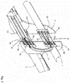
- FIG. 2 is the central region 7 with the rear tractor and the support plates 10 and 11 shown in detail. It can be seen that the straps 1 and 2 are interrupted in the area between the support plates 10 and 11 and connected by the cable pulling means 8 and 9.
- the cable means 8 has a first cable strip 12 on the left support plate 11 and a second cable strip 12 'on the right support plate 10, which are both secured transversely to the longitudinal direction of the upper webbing 1 and along its length on the support plates.
- the cable pull means 9 has two cable pull strips 13 and 13 'which are both fixed transversely to the longitudinal direction of the lower strap 2 and along the length thereof on the support plates.
- the cable trays 12, 12 ', 13 and 13' have a number of several deflection points 14, which are provided for the deflection of one or more traction cables.
- deflection points 14 In the illustrated embodiment of the orthosis four deflection points 14 are provided. But it could also be more or less deflection points can be used as long as a cable can be realized in the manner of a pulley for the rear tractor unit.
- two pull lines are used in a cable pull means to produce two cables lying next to each other between the cable pull rails.
- tug lines 15 and 15 ' between the middle deflection points 14 on the Seilancemann 12' brought to the cable means 8.
- the two pulling lines 15 and 15 ' are alternately guided between the deflection points 14 of the left Seilancemann 12 and the right Seilologymann 12' back and forth until a tensile force ratio of 1: 4 is present.
- the tug 15 extends around the upper two deflection points 14 of the cable trays 12 and 12 'and pull line 15' to the lower two deflection points 14 of the cable trays 12 and 12 '.
- the tug lines 15 and 15 ' are returned between the central deflection points 14 of the Seiladormann 12'.
- the force when tightening the tethers 15 and 15 ' is distributed through the guide between the deflection points 14 over the entire width of the upper webbing 1.
- two pull lines 16 and 16 ' alternately between the deflection points 14 of the left Seilanceance 13 and the right Seilzugruc 13' back and forth, so that the force in train to the pull lines 16 and 16 'on the Width of the lower strap 2 is distributed.
- the deflection points 14 may be formed as simple curves on nubs or the same or as rollers.
- the traction lines bridge the gap between the support plates at the height of the straps and thus form part of the straps.
- the tethers 15 and 15 'enter at least approximately centrally to the width of the upper webbing 1 in the cable means 8 on and off again.
- the leadership can z. B. are formed by a curved channel.
- the access point 18 of the tethers 16 and 16 ' is at least approximately centered to the width of the webbing 2. At this access point 18 all tie lines run together and can be tightened simultaneously by train in the same direction. From the access point 18, the pull lines form a common tension element, z. B.
- FIG. 2 is also the design of the support plates 10 and 11 can be seen.
- the support plates 10 and 11 extend over the upper and lower webbing 1 and 2, so that the webbings 1 and 2 are kept spaced from each other. The distance is at least 5 cm, preferably the distance is about 10 cm.
- the support plates 10 and 11 are in FIG. 2 and 3a shown in an expanded state of the rear tractor in which they are located far from each other. In FIG. 3b the rear tractor is shown in a tightened condition in which the support plates 10 and 11 are located less far from each other; In the illustrated position, the support plates are almost to each other for ease of understanding.
- the support plates 10 and 11 are connected by means of the rear tractor unit and movable on each other, by means of the common drawstring both Seilzugsch 8 and 9 can be uniformly tightened and the support plates 10 and 11 at least approximately parallel to each other.
- the support plates 10 and 11 support on the one hand the straps relative to each other and on the other hand they serve to tighten the rear train unit for uniform transmission of the compressive force on the rear pelvic area.
- the support plates 10 and 11 are mirror-symmetrical to a longitudinal axis formed by the belt unit. In a lower region on the lower webbing 1, the support plates 10 and 11 are designed to be wider than in an upper region on the upper webbing 2. Overall, the upper webbing 1 and the lower webbing 2 and the support plates 10 and 11 are arranged such that in the front and lateral pool area a freely accessible space between the straps is formed and the lowest possible coverage in the rear pelvic area is done by the support plates. Also, the free space between the support plates 10 and 11 is increased by the straps interrupted there and by the tethers 15, 15 'and 16, 16' are replaced. The space is important for the care of the patient, as explained above.
- FIG. 3a the rear traction unit of the orthosis is shown in a wide open state.
- the FIG. 3a equals to FIG. 1
- the drawstring 19 for actuating the cable means 8 and 9 is not tightened and lies in FIG. 3a further right.
- the rear traction unit of the orthosis in FIG. 3b shown in an approximately closed state.
- the drawstring 19 is tightened and the cable means 8 and 9 are tightened, the drawstring 19 in FIG. 3b further left.
- a complete closure of the rear tractor unit so that the support plates 10 and 11 abut each other, to avoid, because then a further fine adjustment of the compression force of the orthosis is not possible.
- the drawstring 19 has an elastic region 21 which is extensible in the pulling direction and lies under a cover 20 in the relaxed state.
- the cover 20 is attached to the drawstring 19.
- an elastic region z. B. a rubber band can be used in the drawstring.
- the drawstring 19 has an indicator 22 for indicating an applied tensile force as a function of the elongation of the elastic region 21.
- the indicator 22 may, for example, by the elastic region itself or a marker, for. B. in the form of a color strip, are formed on the elastic region.
- the elastic region 21 lies under the cover 20 when the drawstring 19 is not tightened.
- the indicator 22 is then covered by the cover 20.
- a fixing unit which fixes the drawstring 19 on the lower webbing 2.
- a fastening unit can again a Velcro be used, wherein z. B. a barb surface on the drawstring 19 cooperates with a loop surface on the lower webbing.
- a hook or button connection could serve as a fastening unit between drawstring 19 and lower webbing 2.
Landscapes
- Health & Medical Sciences (AREA)
- Nursing (AREA)
- Orthopedic Medicine & Surgery (AREA)
- Engineering & Computer Science (AREA)
- Biomedical Technology (AREA)
- Heart & Thoracic Surgery (AREA)
- Vascular Medicine (AREA)
- Life Sciences & Earth Sciences (AREA)
- Animal Behavior & Ethology (AREA)
- General Health & Medical Sciences (AREA)
- Public Health (AREA)
- Veterinary Medicine (AREA)
- Orthopedics, Nursing, And Contraception (AREA)
Applications Claiming Priority (1)
| Application Number | Priority Date | Filing Date | Title |
|---|---|---|---|
| CH01354/15A CH711550A2 (en) | 2015-09-18 | 2015-09-18 | Orthosis for pelvic stabilization. |
Publications (1)
| Publication Number | Publication Date |
|---|---|
| EP3143971A1 true EP3143971A1 (fr) | 2017-03-22 |
Family
ID=57286192
Family Applications (1)
| Application Number | Title | Priority Date | Filing Date |
|---|---|---|---|
| EP16188402.8A Withdrawn EP3143971A1 (fr) | 2015-09-18 | 2016-09-12 | Orthèse destinée à la stabilisation du bassin |
Country Status (3)
| Country | Link |
|---|---|
| US (1) | US20170079829A1 (fr) |
| EP (1) | EP3143971A1 (fr) |
| CH (1) | CH711550A2 (fr) |
Cited By (1)
| Publication number | Priority date | Publication date | Assignee | Title |
|---|---|---|---|---|
| DE102019115325A1 (de) * | 2019-06-06 | 2020-12-10 | Spektramed Gmbh | Medizintechnische Vorrichtung zur Krafteinwirkung auf das Becken des Lebewesens sowie Verfahren und Verwendung |
Families Citing this family (3)
| Publication number | Priority date | Publication date | Assignee | Title |
|---|---|---|---|---|
| US10918561B2 (en) * | 2012-09-14 | 2021-02-16 | Recovery Force, LLC | Compression device |
| CA2962221A1 (fr) * | 2016-07-05 | 2018-01-05 | Joseph O. M. Lawrence | Bande de tension corporelle |
| CN112155819B (zh) * | 2020-10-23 | 2022-08-09 | 张菲 | 一种产科护理用术后康复装置 |
Citations (4)
| Publication number | Priority date | Publication date | Assignee | Title |
|---|---|---|---|---|
| DE10033737A1 (de) * | 2000-07-12 | 2002-01-31 | Ekkehard Gorski | Beckengurt |
| US20030073942A1 (en) * | 1999-02-02 | 2003-04-17 | Charlotte-Mecklenburg Hospital Authority D/B/A Carolinas Medical Center | Pelvic splint and associated method |
| EP1337207B1 (fr) | 2000-11-14 | 2006-08-23 | Bio Cybernetics International | Dispositif pour traumatisme orthetique |
| WO2014028248A1 (fr) | 2012-08-13 | 2014-02-20 | The United States Of America As Represented By The Secretary Of The Army | Dispositif pour traumatisme pelvien |
Family Cites Families (9)
| Publication number | Priority date | Publication date | Assignee | Title |
|---|---|---|---|---|
| JPH0714406B2 (ja) * | 1985-06-19 | 1995-02-22 | 野口 仁美 | 骨盤固定バンド |
| US4696291A (en) * | 1986-03-06 | 1987-09-29 | Tyo James H | Pelvic stabilization device |
| US7473235B2 (en) * | 2000-12-05 | 2009-01-06 | Orthomerica Products, Inc. | Lightweight modular adjustable prophylactic hip orthosis |
| US6676620B2 (en) * | 2000-12-05 | 2004-01-13 | Orthomerica Products, Inc. | Modular orthosis closure system and method |
| US7037284B2 (en) * | 2002-01-17 | 2006-05-02 | Diane Lee | Specific pelvic compression belt |
| US20070232973A1 (en) * | 2006-04-04 | 2007-10-04 | Serola Richard J | Sacroiliac belt and composite structure |
| US20130324898A1 (en) * | 2012-06-05 | 2013-12-05 | Adrian Abram Polliack | Device and method for stabilization of a fractured pelvis or an injured neck |
| WO2015134506A1 (fr) * | 2014-03-04 | 2015-09-11 | Revmedx, Inc. | Ceintures pelviennes |
| FR3034981B1 (fr) * | 2015-04-20 | 2017-05-05 | Damien Bratic | Dispositif de decompression vertebrale |
-
2015
- 2015-09-18 CH CH01354/15A patent/CH711550A2/en not_active Application Discontinuation
-
2016
- 2016-09-08 US US15/259,593 patent/US20170079829A1/en not_active Abandoned
- 2016-09-12 EP EP16188402.8A patent/EP3143971A1/fr not_active Withdrawn
Patent Citations (4)
| Publication number | Priority date | Publication date | Assignee | Title |
|---|---|---|---|---|
| US20030073942A1 (en) * | 1999-02-02 | 2003-04-17 | Charlotte-Mecklenburg Hospital Authority D/B/A Carolinas Medical Center | Pelvic splint and associated method |
| DE10033737A1 (de) * | 2000-07-12 | 2002-01-31 | Ekkehard Gorski | Beckengurt |
| EP1337207B1 (fr) | 2000-11-14 | 2006-08-23 | Bio Cybernetics International | Dispositif pour traumatisme orthetique |
| WO2014028248A1 (fr) | 2012-08-13 | 2014-02-20 | The United States Of America As Represented By The Secretary Of The Army | Dispositif pour traumatisme pelvien |
Cited By (3)
| Publication number | Priority date | Publication date | Assignee | Title |
|---|---|---|---|---|
| DE102019115325A1 (de) * | 2019-06-06 | 2020-12-10 | Spektramed Gmbh | Medizintechnische Vorrichtung zur Krafteinwirkung auf das Becken des Lebewesens sowie Verfahren und Verwendung |
| WO2020244713A1 (fr) | 2019-06-06 | 2020-12-10 | Spektramed Gmbh | Dispositif médical destiné à exercer une force sur le bassin d'un être vivant, procédé associé et utilisation |
| DE102019115325B4 (de) | 2019-06-06 | 2023-06-15 | Spektramed Gmbh | Medizintechnische Vorrichtung zur Krafteinwirkung auf das Becken des Lebewesens sowie Herstellungsverfahren |
Also Published As
| Publication number | Publication date |
|---|---|
| US20170079829A1 (en) | 2017-03-23 |
| CH711550A2 (en) | 2017-03-31 |
Similar Documents
| Publication | Publication Date | Title |
|---|---|---|
| EP2844197B1 (fr) | Dispositif tendeur pour orthèses | |
| DE69408710T2 (de) | Rücken-Bauchbezüglicher Stützgürtel | |
| WO2013182685A1 (fr) | Dispositif de serrage pour orthèses | |
| EP0198482B1 (fr) | Bandage de fixation | |
| EP3210581A1 (fr) | Bandage pour pied destiné à la thérapie par compression des lymphoedèmes | |
| EP3143971A1 (fr) | Orthèse destinée à la stabilisation du bassin | |
| EP2605731B1 (fr) | Dispositif tendeur pour orthèses | |
| EP0379929B1 (fr) | Bandage claviculaire | |
| EP1940330B1 (fr) | Dispositif de support pour cage thoracique | |
| DE3415657C2 (de) | Fußgelenkbandage | |
| EP2452656B1 (fr) | Bandage fixe pour la fixation d'un patient | |
| EP1398010B1 (fr) | Bandage claviculaire | |
| EP2026722B1 (fr) | Bandage de sécurité avec manchons pour les cuisses | |
| EP3135259B1 (fr) | Dispositif destine a attacher un patient sur un support | |
| DE3708680C2 (de) | Krankentransportvorrichtung | |
| DE102022117881B4 (de) | Orthese oder bandage für den lumbalbereich | |
| WO2010139084A1 (fr) | Orthèse | |
| DE60030335T2 (de) | Orthetische traumavorrichtung | |
| DE102018132931B4 (de) | Extensionssystem | |
| DE20204936U1 (de) | Dynamisierte Reklinationsorthese mit Sternal- und Symphysenpelotte | |
| DE947332C (de) | Streckguertel fuer die Behandlung von Rueckenverletzungen | |
| AT502986B1 (de) | Stützbandage | |
| DE102021120725A1 (de) | Vorrichtung zur Behandlung der menschlichen Wirbelsäule | |
| DE8900721U1 (de) | Clavicula-Bandage | |
| DE102015006329B3 (de) | Koppelelemente zum Koppeln von Gurten, insbesondere für Gurte von Bandagen oder Orthesen |
Legal Events
| Date | Code | Title | Description |
|---|---|---|---|
| PUAI | Public reference made under article 153(3) epc to a published international application that has entered the european phase |
Free format text: ORIGINAL CODE: 0009012 |
|
| AK | Designated contracting states |
Kind code of ref document: A1 Designated state(s): AL AT BE BG CH CY CZ DE DK EE ES FI FR GB GR HR HU IE IS IT LI LT LU LV MC MK MT NL NO PL PT RO RS SE SI SK SM TR |
|
| AX | Request for extension of the european patent |
Extension state: BA ME |
|
| STAA | Information on the status of an ep patent application or granted ep patent |
Free format text: STATUS: THE APPLICATION IS DEEMED TO BE WITHDRAWN |
|
| 18D | Application deemed to be withdrawn |
Effective date: 20170923 |